Submitted:
14 October 2024
Posted:
15 October 2024
You are already at the latest version
Abstract
Keywords:
1. Introduction
- Parallel System Construction: A coupled effect is generated by the parallel connection of Grid Forming (GFM) and Grid Following (GFL) systems, allowing for the analysis of fault ride-through issues and transient stability under these conditions.
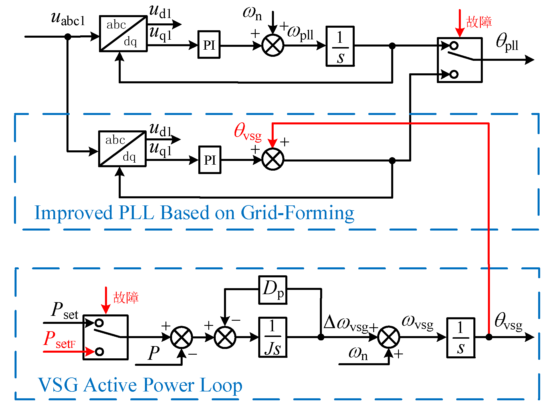
- Power Stability: A mechanical power adjustment loop is introduced in GFM, and a grid-structured improved phase-locked loop is employed in GFL to determine the balance point between GFM and GFL.
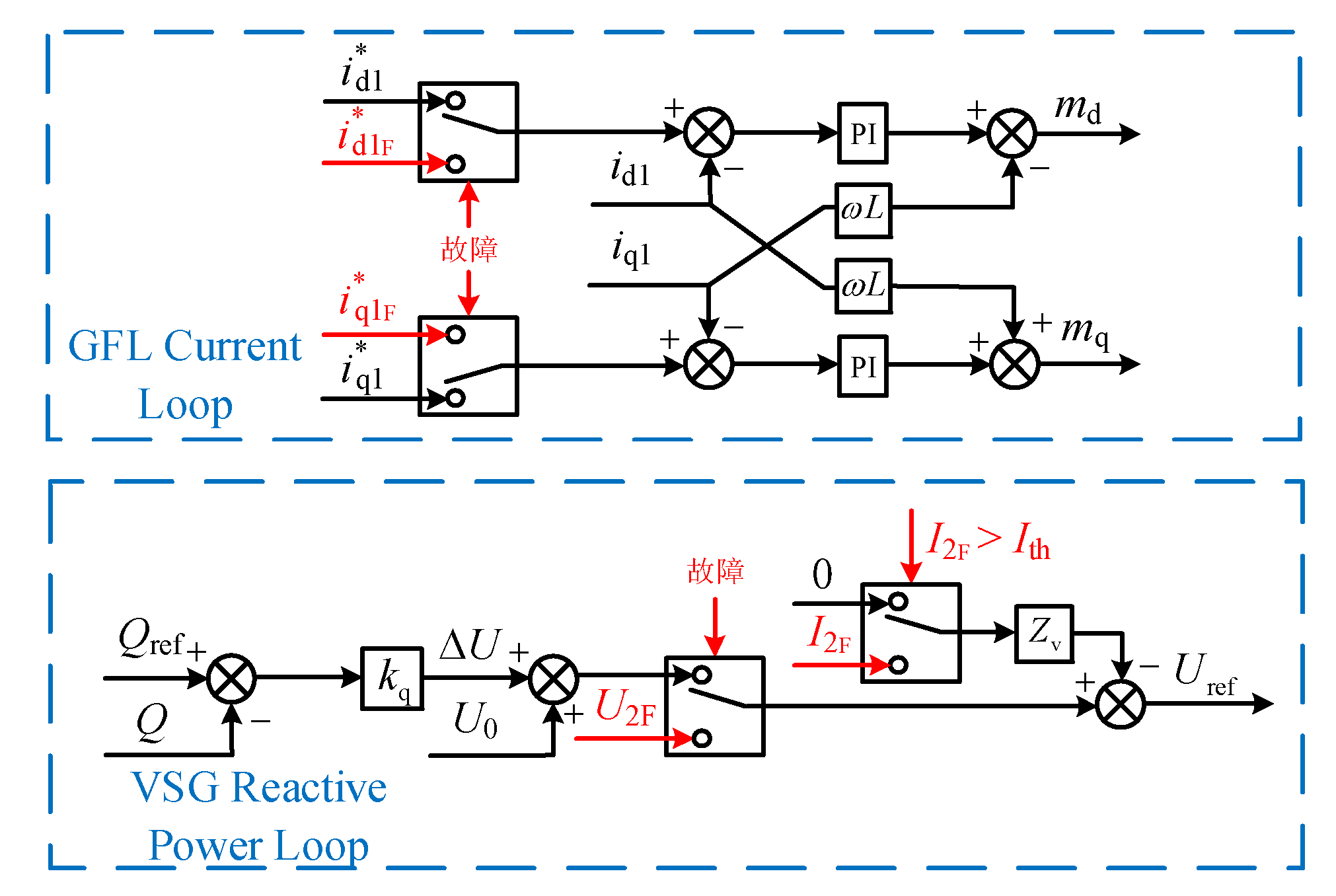
- Reactive Power Locking: The reactive power output that complies with grid guidelines is supported by replacing the reactive power output with the calculated GFM output voltage U2F to support the grid containing GFL.
- Transient Fault Current Control: Transient virtual impedance is utilized to suppress transient overcurrent, preventing excessive short-circuit current from damaging power electronic devices in GFM.
2. Parallel System of Grid-Following and Grid-Forming Converters
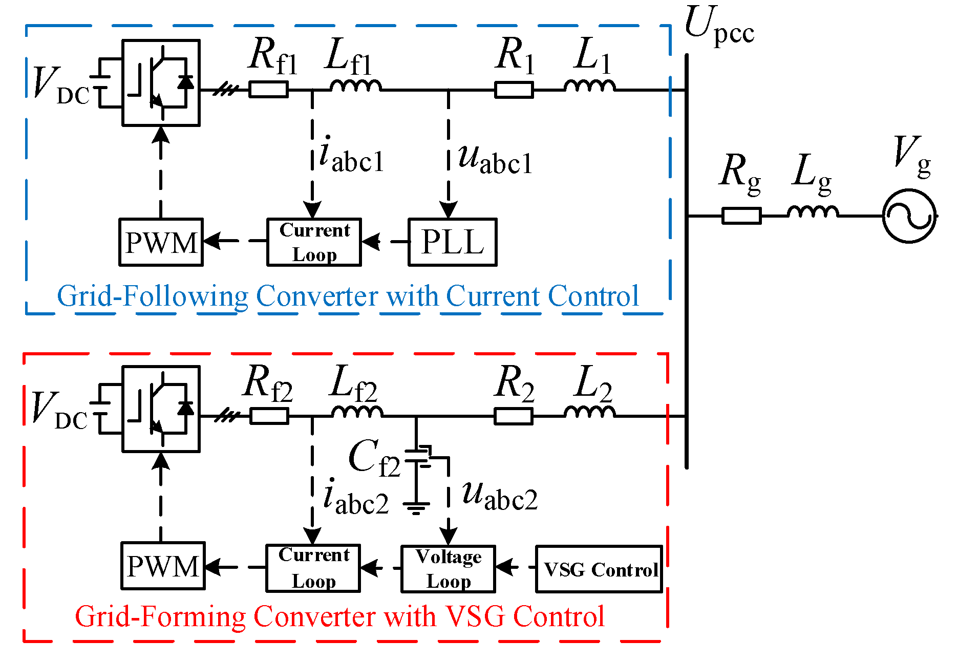
2.1. Main Circuit System Topology
2.2. Grid-Following Converter Based on Current Control
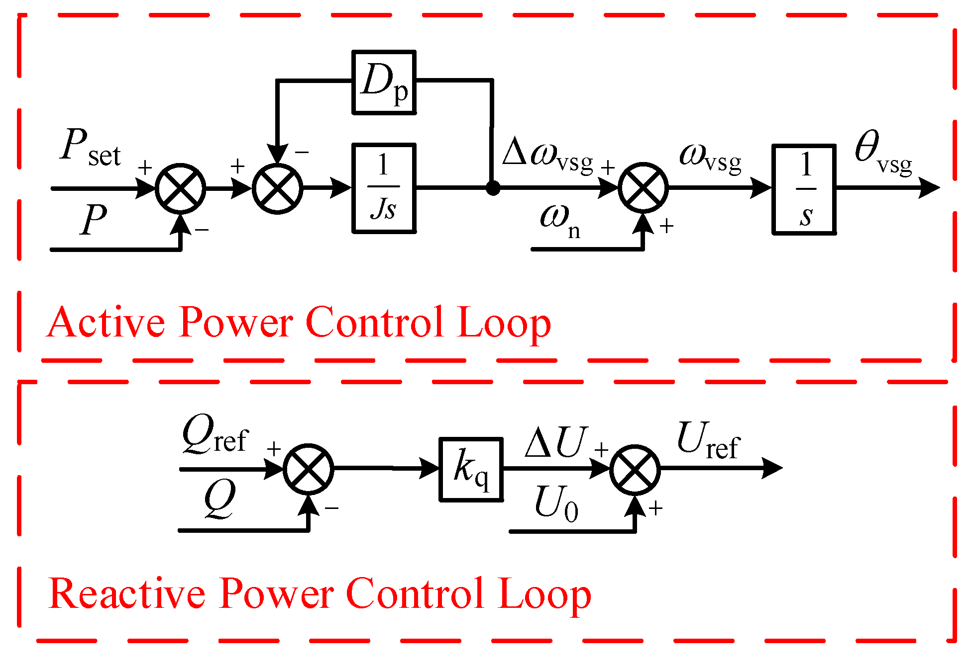
2.3. Grid-Forming Converter Based on VSG Control
3. Mathematical Model and Transient Characteristics of Parallel System
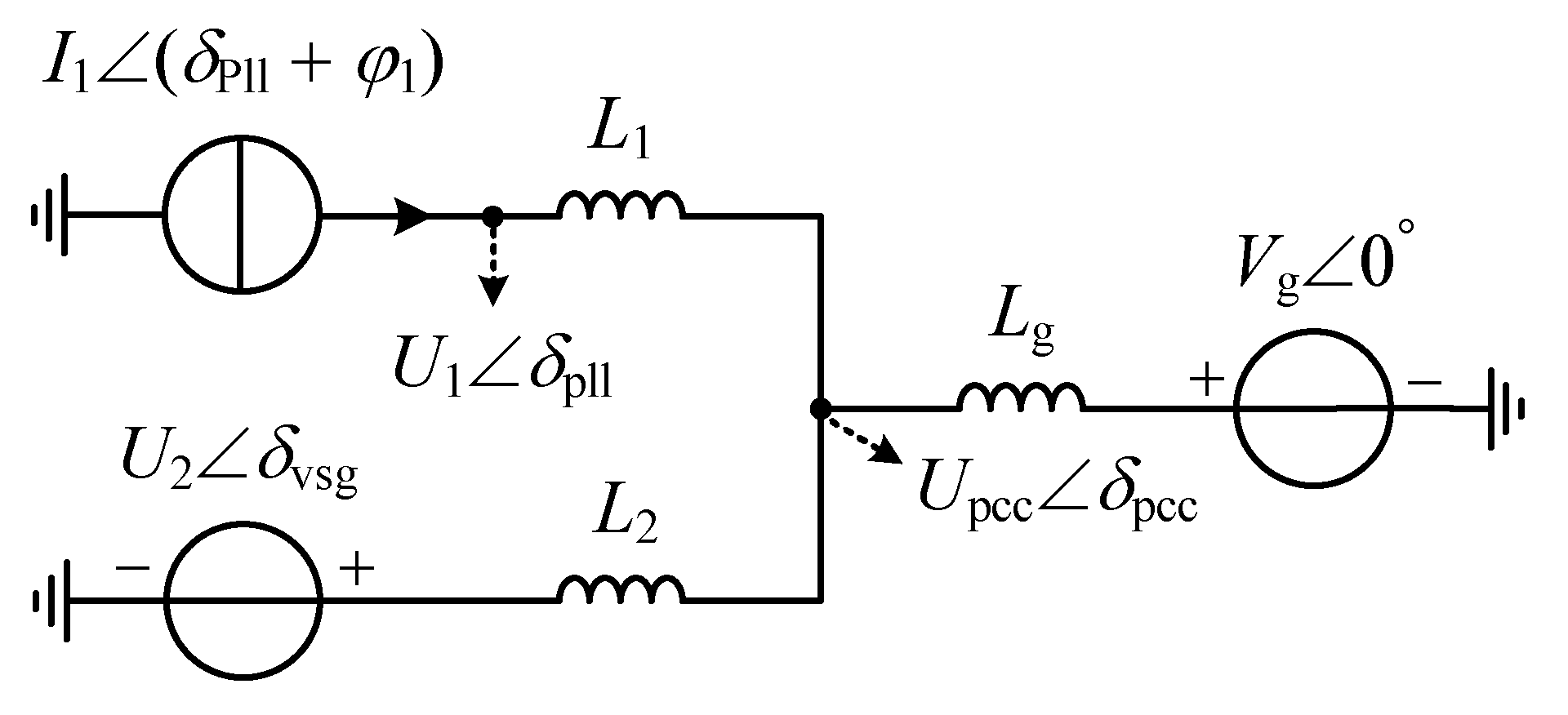
3.1. Mathematical Modeling of HGS.
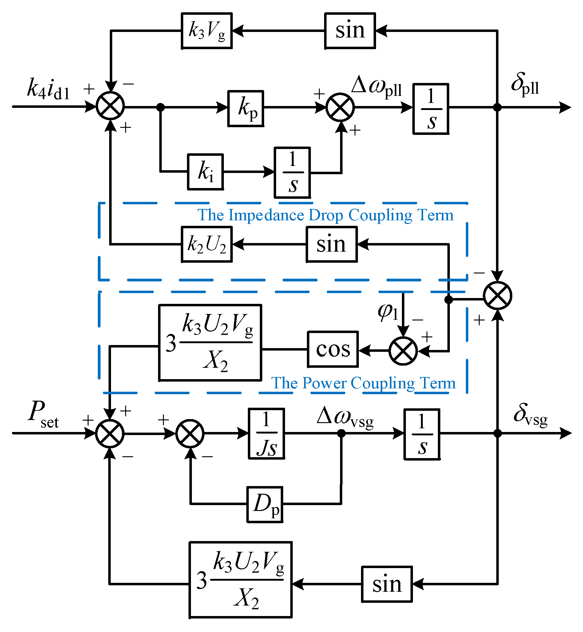
3.2. Transient Stability Analysis Considering Coupling Effects
4. Fault Ride-through Control of the HGS
4.1. Transient Power Angle Control
4.2. Fault Current Control
4.2.1. Steady-State Current Control
4.2.2. Steady-State Current Control
5. Case Study
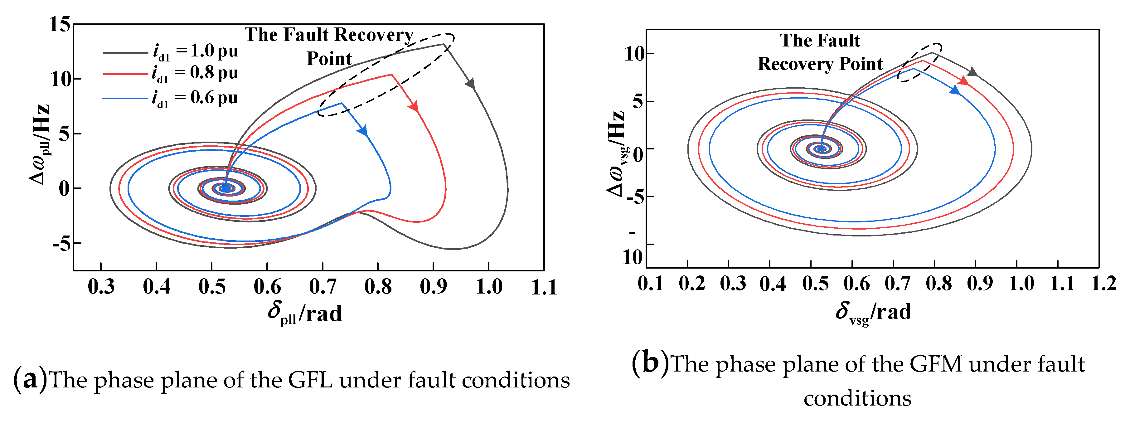
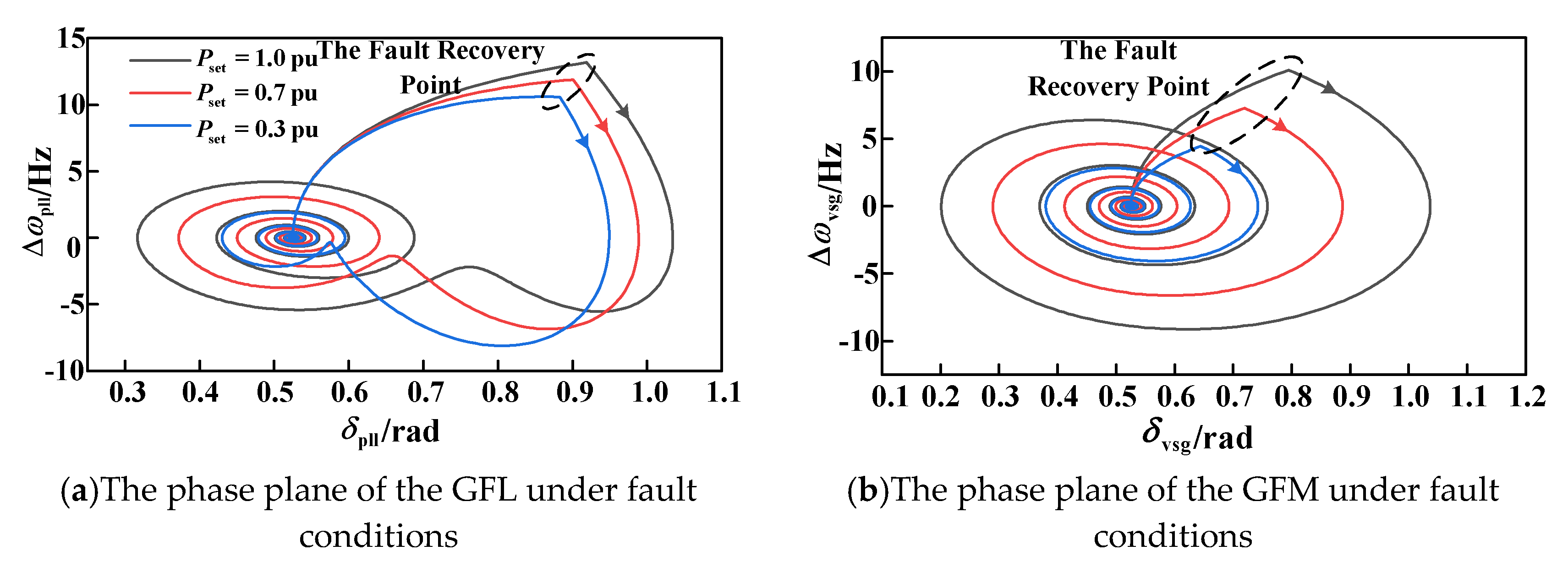
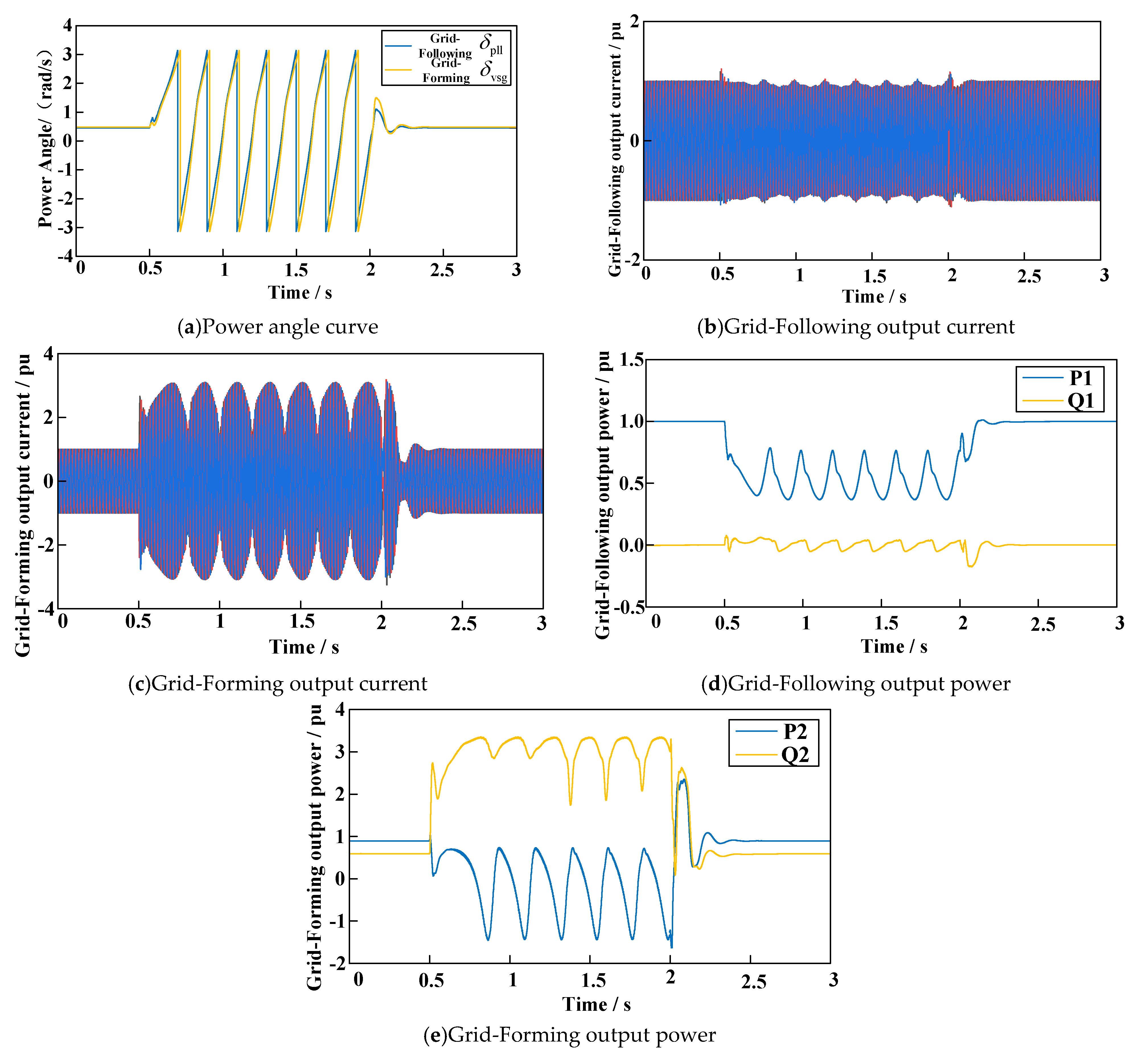
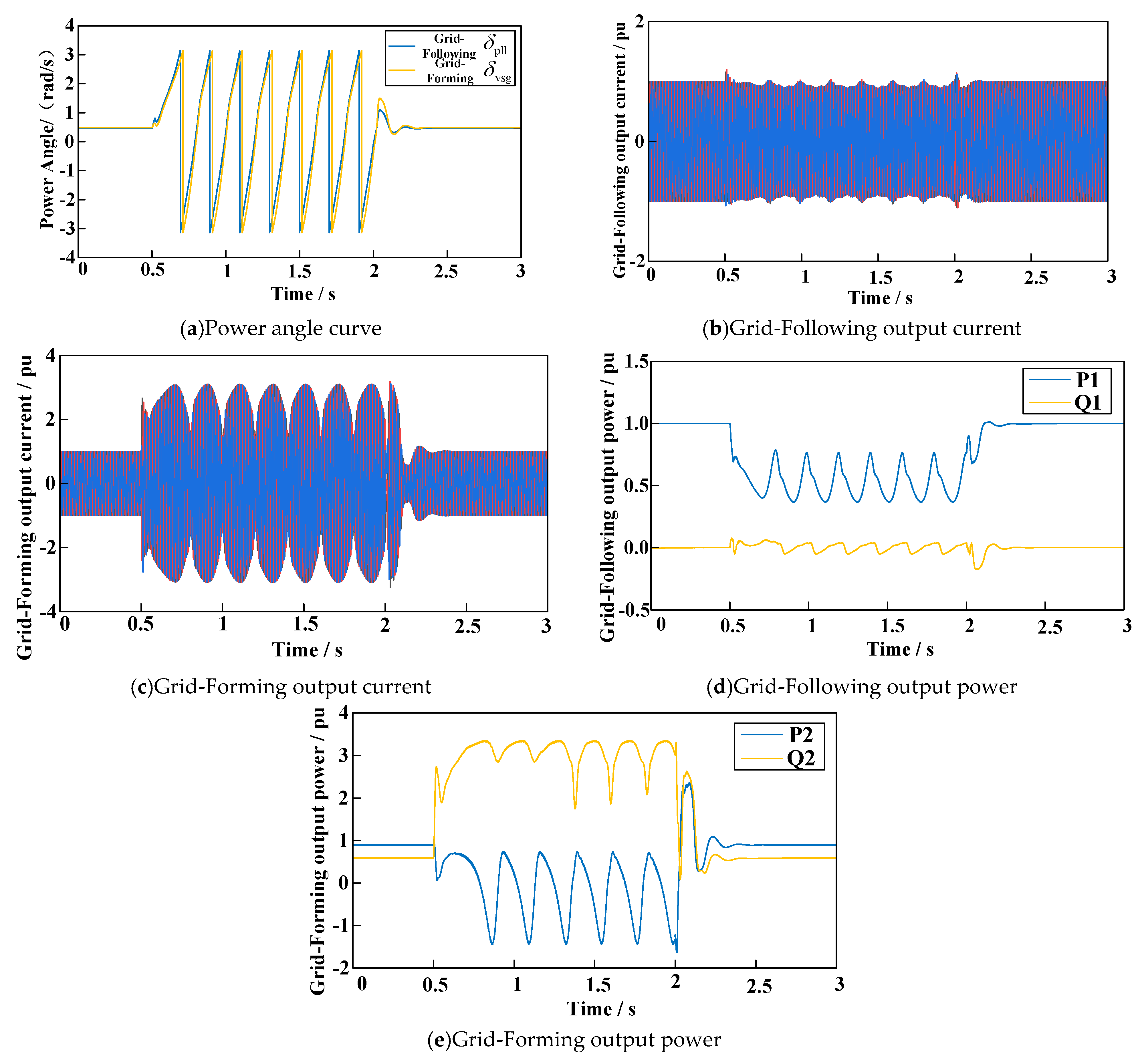
5.1. Output Characteristics of GFM and GFL during Fault Conditions
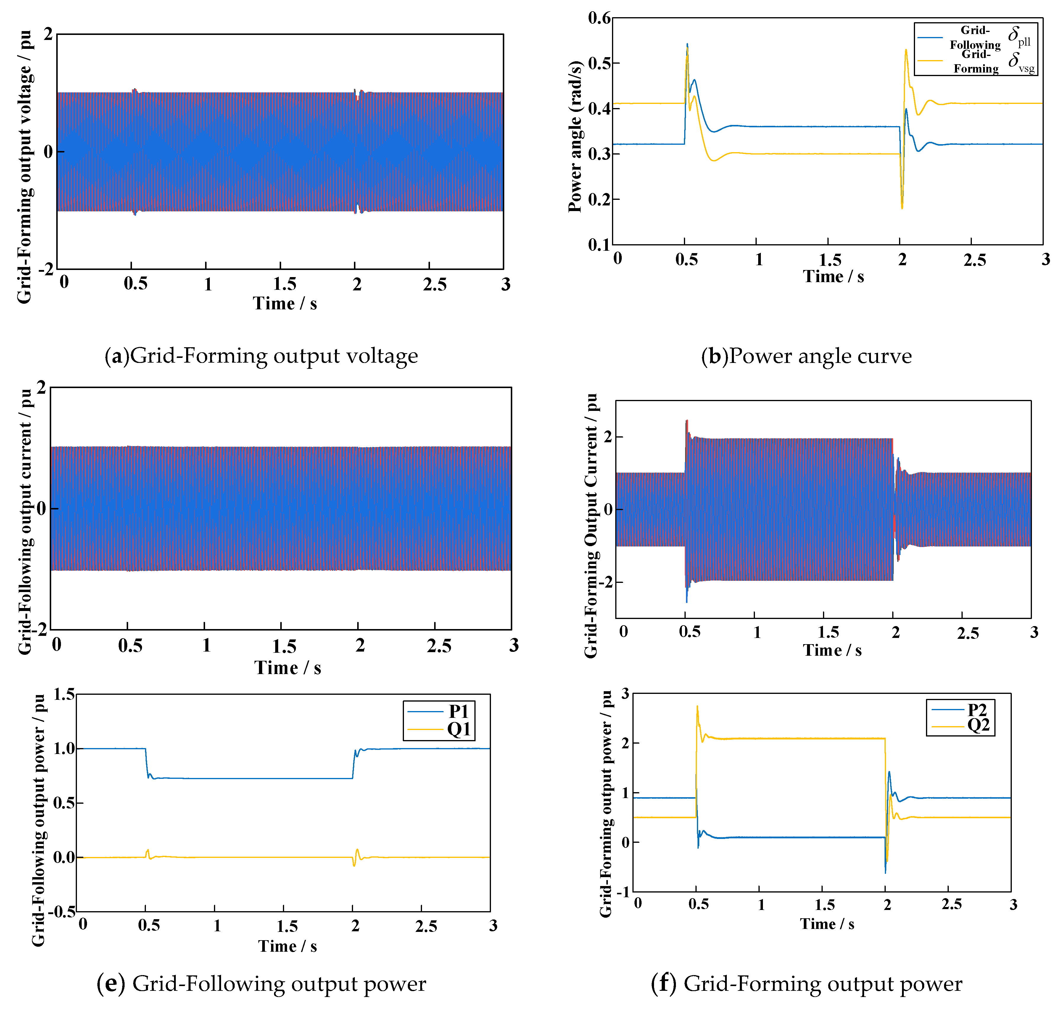
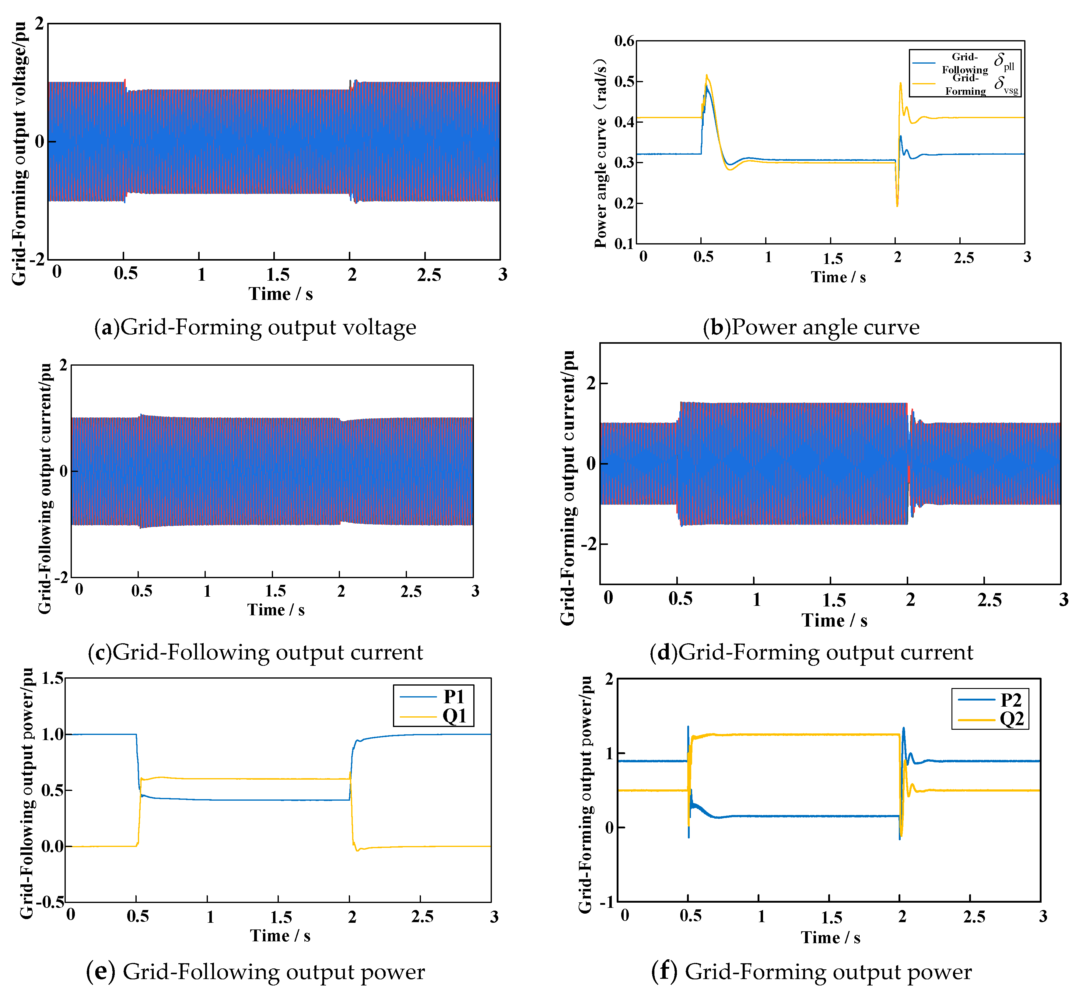
5.2. Verification of the Proposed Fault Ride-through Control Strategy
6. Conclusion
Author Contributions
Funding
Data Availability Statement
Conflicts of Interest
References
- Y. Wang, S. Lou, Y. Wu and S. Wang, “Flexible Operation of Retrofitted Coal-Fired Power Plants to Reduce Wind Curtailment Considering Thermal Energy Storage,” IEEE Transactions on Power Systems, vol. 35, no. 2, pp. 1178-1187, March 2020.
- B. Zhou et al., “Optimal Scheduling of Biogas–Solar–Wind Renewable Portfolio for Multicarrier Energy Supplies,” IEEE Transactions on Power Systems, vol. 33, no. 6, pp. 6229-6239, Nov. 2018.
- T. Ding, R. Bo, H. Sun, F. Li and Q. Guo, “A Robust Two-Level Coordinated Static Voltage Security Region for Centrally Integrated Wind Farms,” IEEE Transactions on Smart Grid, vol. 7, no. 1, pp. 460-470, Jan. 2016.
- Rosso R, Engelken S, Liserre M, “Robust Stability Investigation of the Interactions Among Grid-Forming and Grid-Following Converters,” IEEE Journal of Emerging and Selected Topics in Power Electronics, 2020, 8: 991-1003.
- Yang C, Huang L, Xin H, et al., “Placing Grid-Forming Converters to Enhance Small Signal Stability of PLL-Integrated Power Systems, “ IEEE Transactions on Power Systems, 2020. 36: 991-1003.
- Zhao X, Flynn D, “Stability enhancement strategies for a 100% grid-forming and grid-following converter-based Irish power system, “ IET Renewable Power Generation, 2022, 16: 125-138.
- Taul M G, Wang X F, Davari P, et al. “Current Limiting Control With Enhanced Dynamics of Grid-Forming Converters During Fault Conditions, “ IEEE Journal of Emerging and Selected Topics in Power Electronics, 2020, 8: 1062-1073.
- “Ieee standard for interconnection and interoperability of inverter-based resources (ibrs) interconnecting with associated transmission electric power systems, “ IEEE Std 2800-2022, pp. 1–180, 2022.
- Göksu Ö, Teodorescu R, Bak C L, et al. “Instability of Wind Turbine Converters During Current Injection to Low Voltage Grid Faults and PLL Frequency Based Stability Solution,” IEEE Transactions on Power Systems, 2014, 29: 1683-1691.
- Weise B. “Impact of K-factor and active current reduction during fault-ride-through of generating units connected via voltage-sourced converters on power system stability, “ IET Renewable Power Generation, 2015, 9: 25-36.
- He X Q, Geng H, Xi J B, et al. “Resynchronization analysis and improvement of grid-connected VSCs during grid faults, “ IEEE Journal of Emerging and Selected Topics in Power Electronics, 2021, 9: 438-450.
- Ma S, Geng H, Liu L, et al. “Grid-synchronization stability improvement of large scale wind farm during severe grid fault, “ IEEE Transactions on Power Systems, 2018, 33: 216-226.
- Shi K, Song W, Xu P F, et al. “Low-voltage ride-through control strategy for a virtual synchronous generator based on smooth switching,” IEEE Access, 2017, 6:2703–2711.
- J. Xi, J. Wang, J. Zhang, Y. Zhang, C. Su and C. Liu, “Current Limiting Strategy of Grid-forming Converter Based on Additional Current Loop,” 2022 4th International Conference on Smart Power & Internet Energy Systems (SPIES), Beijing, China, 2022, pp. 328-332.
- Shuai Z K, Shen C, Xuan Liu, et al. “Transient angle stability of virtual synchronous generators using Lyapunov’s direct method,” IEEE Transactions on Smart Grid, 2019, 10: 4648-4661.
- Y. Zheng, T. Wang, S. He, Y. Wu, Y. Kang and D. Liu, “Analytical Expression of Short Circuit Current for Virtual Synchronous Generator with Improved Low Voltage Ride Through Control Strategy,” 2023 IEEE Power & Energy Society General Meeting (PESGM), Orlando, FL, USA, 2023, pp. 1-5.
- Chen J, Prystupczuk F, O’ Donnell T. “Use of voltage limits for current limitations in grid-forming converters,” CSEE Journal of Power and Energy Systems, 2020, 6: 259-269.
- H. Cheng, Z. Shuai, C. Shen, X. Liu, Z. Li and Z. J. Shen, “Transient Angle Stability of Paralleled Synchronous and Virtual Synchronous Generators in Islanded Microgrids,” IEEE Transactions on Power Electronics, vol. 35, no. 8, pp. 8751-8765, Aug. 2020.
- Z. Tian et al., “Transient Synchronization Stability of an Islanded AC Microgrid Considering Interactions Between Grid-Forming and Grid-Following Converters,” IEEE Journal of Emerging and Selected Topics in Power Electronics, vol. 11, no. 4, pp. 4463-4476, Aug. 2023.
- Paquette A D, Divan D M. “Virtual impedance current limiting for inverters in microgrids with synchronous generators,” IEEE Transactions on Industry Applications, 2015, 51: 1630-1638.


| Parameter | Value |
|---|---|
| DC bus voltage (VDC/V) | 800 |
| Grid voltage amplitude (Vg/V) | 311 |
| Grid angular frequency (ωg/(rad/s)) | 314 |
| GFL line inductance (L1/mH) | 3.2 |
| GFM line inductance(L2/ mH) | 3.2 |
| Grid inductance(Lg/ mH) | 4 |
| GFM moment of inertia (J/(kg/m2)) | 5 |
| GFM active power damping coefficient (Dp) | 130 |
| GFM reactive power droop coefficient(kq) | 0.01 |
Disclaimer/Publisher’s Note: The statements, opinions and data contained in all publications are solely those of the individual author(s) and contributor(s) and not of MDPI and/or the editor(s). MDPI and/or the editor(s) disclaim responsibility for any injury to people or property resulting from any ideas, methods, instructions or products referred to in the content. |
© 2024 by the authors. Licensee MDPI, Basel, Switzerland. This article is an open access article distributed under the terms and conditions of the Creative Commons Attribution (CC BY) license (http://creativecommons.org/licenses/by/4.0/).


