1. Introduction
Human hands are essential in our daily lives, performing a variety of tasks such as touching, gripping, feeling, holding, manipulating, and caring. They provide a substantial contribution to our identity and self-perception. Carrying out daily activities becomes difficult for people who do not have hands, resulting in slower and less efficient work performance and a limited ability to complete tasks [
1,
2]. In addition, individuals experience social shame and feelings of insecurity as a result of others' avoidance.
Prosthetic devices can significantly improve the quality of life for individuals with limb loss by providing independence and mobility. Prostheses are external devices that replace missing or defective limb segments (arms and legs), including all devices attached to a limb for structural or functional purposes, such as bone-anchored prostheses [
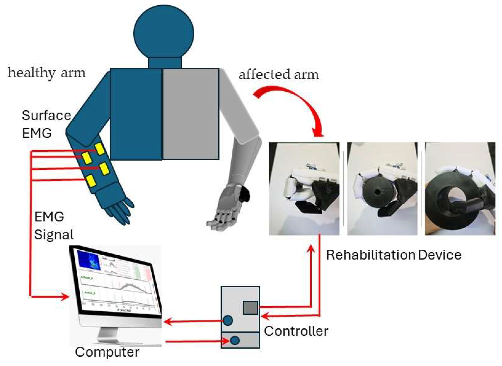
3]. However, in this research, we focus on developing a prosthetic arm for rehabilitation purposes, targeting hemiplegic patients who are unable to open and close their hands due to a blockage of their nerve pathways caused by neurofunctional disorders such as apoplexy as shown in
Figure 1. These patients can use a rehabilitative automated prosthetic arm to help them open and close their hands. This automated prosthetic arm robot's movements, such as opening and closing fingers, are expected to be more effective in the rehabilitation process than passive movements without the use of any equipment [
4].
Integrating Electromyography (EMG) technologies into prosthetic arms is critical for improving functionality and usability [
5,
6,
7,
8,
9]. EMG sensors monitor electrical signals produced by muscular contractions in the residual limb, providing useful feedback for intuitive control of the prosthetic arm's movements. By recording these signals, EMG allows users to start and control specific tasks with natural muscle movements, resulting in a more intuitive and responsive engagement with their prosthetic device. We will employ surface EMG signals to relay the patient's muscle signal, allowing them to open and close their hands. We will design and develop a rehabilitation prosthesis that suits this task as part of the total contribution of the automated control rehabilitation prosthesis arm [
10,
11,
12].
The primary objective of this project is to design and fabricate an automated control prosthetic arm that can improve the quality of life for amputees in terms of functionality, ease of use, lightweight, portability, and cost-effectiveness, ensuring that all amputees can utilize it. The prosthetic arm will feature 3D-printed materials, strings that serve as tendons for the fingers, and algorithms for the mechanisms. The arm will be powered by a battery and can be controlled wirelessly via a smartphone app. The algorithms will be designed to control the arm movements based on user feedback, with EMG sensors detecting the user's movements and providing feedback.
The first objective of this research is to study and analyze current prosthetic arms and components available on the market, identifying their limitations and potential improvements. Second, we aim to determine the appropriate product design specifications (PDS) for conceptual design development. Third, we will apply the concept scoring evaluation matrix to select the optimal prosthesis design concept. Finally, we will design and fabricate the prosthetic arm and test its prototype. Additive manufacturing techniques like 3D printing are used for fabricating this prosthesis [
13,
14]. 3D printing offers design freedom reduces manufacturing time, minimizes material waste, and facilitates the creation of customized prostheses. Designing and manufacturing a functional prosthetic arm involves overcoming challenges in both design and manufacturing processes. The primary goal is to create a prosthetic arm robot that will improve the quality of opening and closing the hands of the patient during rehabilitation.
2. Materials and Methods
2.1. Methodology
This section examines various aspects of existing designs, including their design features, materials, mechanisms, and overall effectiveness. By analyzing previous works, the report aims to identify strengths, weaknesses, and areas for improvement in current prosthetic arm designs. Previous research has focused more on the development of prosthetic arms as replacements for amputee arms [
15,
16,
17,
18,
19,
20,
21,
22,
23,
24]. This study focuses on designing a prosthetic arm that supports rehabilitation tools for opening and closing fingers.
Table 1 shows previous researchers' contributions to prosthetic arm research.
2.2. Product Design Specification and Concept Analysis
Product Design Specification (PDS) criteria were established to guide the design and fabrication process through several design concepts as shown in
Table 2. The first step in developing a concept design for a prosthetic arm is to identify the common components likely to be employed, as shown in the example of Conceptual Design 3 in
Figure 2. We developed three base design concepts. From the three concepts developed, we evaluated them by using the concept scoring evaluation matrix to identify the best design.
2.3. Design Selection
Several factors can be used to select the best concept design for a prosthetic arm, and a concept scoring evaluation matrix shown in
Table 3, can play a crucial role in this process. In an evaluation matrix, criteria and specific requirements for a prosthetic arm are broken down into categories such as user-friendliness, durability, stability, ease of control, lightweight, easy to assemble, and aesthetic value. The selected criteria ensured that the prosthetic arm would be affordable, easy to use, energy-efficient, customizable, comfortable, low-maintenance, and visually appealing.
Each concept is rated and scored according to how well it meets each criterion, enabling a clear and objective comparison between options. From this evaluation approach, the best concept design offers the optimal combination of features and functionalities for the prosthetic arm. Based on the total value from the scoring evaluation matrix in
Table 3, Conceptual Design 3 had the highest overall rating with a total of 4.22 weight score and was thus selected as the base concept design for the prosthetic arm in this study. Conceptual Design 2 came in second with a total of 3.85 scores, while Conceptual Design 1 was last with a total of 2.80 scores. These rankings were based on a personal evaluation and analysis survey.
Incorporating advantages from each conceptual design will help refine our final design. For instance, the placement of the thumb is important and considered within a range of 35° to 90° from the index finger, as observed in initial drawings where extremes in size hindered object manipulation. Additionally, the optimal positioning of motors is prioritized to avoid component overcrowding and make efficient use of available space as we decided in Conceptual Design 3 for 5 servo motors located at the forearm. The number of parts is also crucial, with a higher quantity facilitating easier repairs or replacements when parts become worn or damaged. While a higher joint ratio enhances stability, the design must balance this with space constraints to ensure practical functionality. The final design will use a 2:2 joint ratio for better stability compared to the 1:1 ratio, taking both stability and space efficiency into account as summarized in
Table 2.
2.4. Flexion Angle for Finger Design
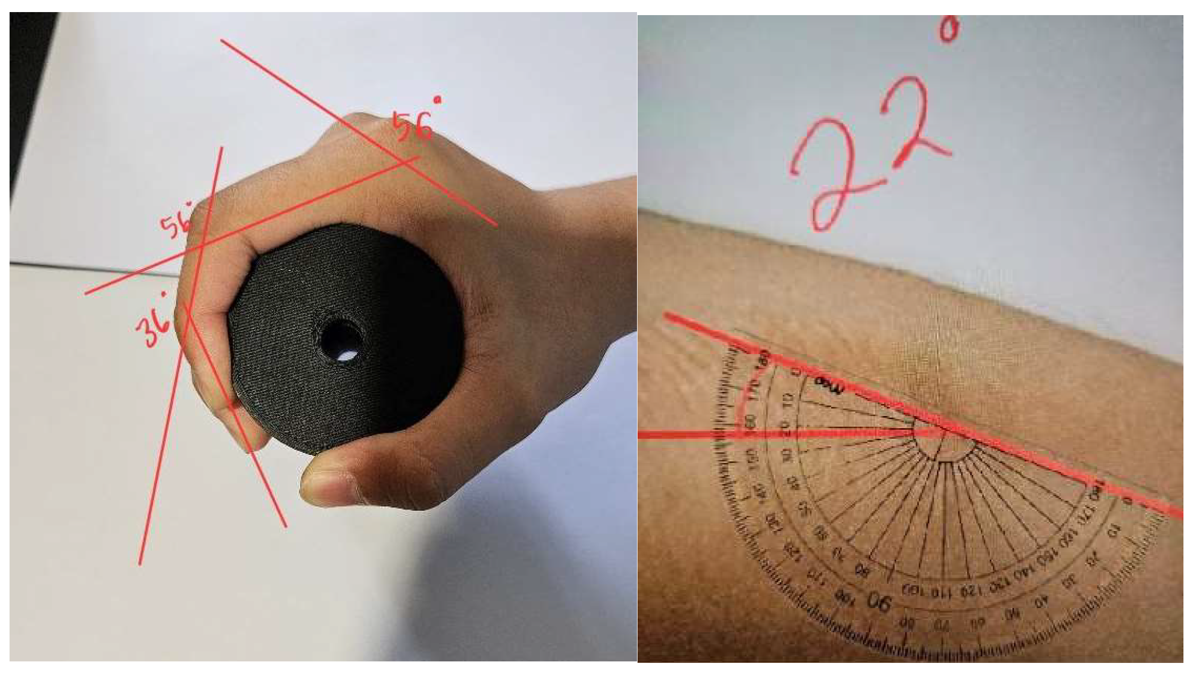
Flexion angles of the hand's joints were measured using a standardized procedure involving cylinders of varying sizes. The procedure ensured accurate measurement of flexion angles at the distal interphalangeal (DIP), proximal interphalangeal (PIP), and metacarpophalangeal (MCP) joints. By meticulously measuring these angles, crucial data were obtained to inform the design and development of the prosthetic arm, optimizing functionality and natural movement. The measured angles provided essential data for designing a prosthetic arm that replicates natural hand movements and flexibility.
The flexion angle procedures involved utilizing both of the author's own hands, left and right, as the subjects for measurement (
Figure 3). This approach ensured consistency and reliability in the data collection process, as the measurements were taken from the same individual under controlled conditions. Accurate measurements of hand and arm dimensions were crucial for designing a customized prosthetic arm. A method involving tracing, marking, and measuring was employed to obtain precise dimensions. These measurements served as the basis for designing a prosthetic arm that prioritized comfort, functionality, and alignment with individual anatomical and biomechanical needs. The procedure is as follows:
Ensure the camera is set up at a consistent angle directly above the subject's hand.
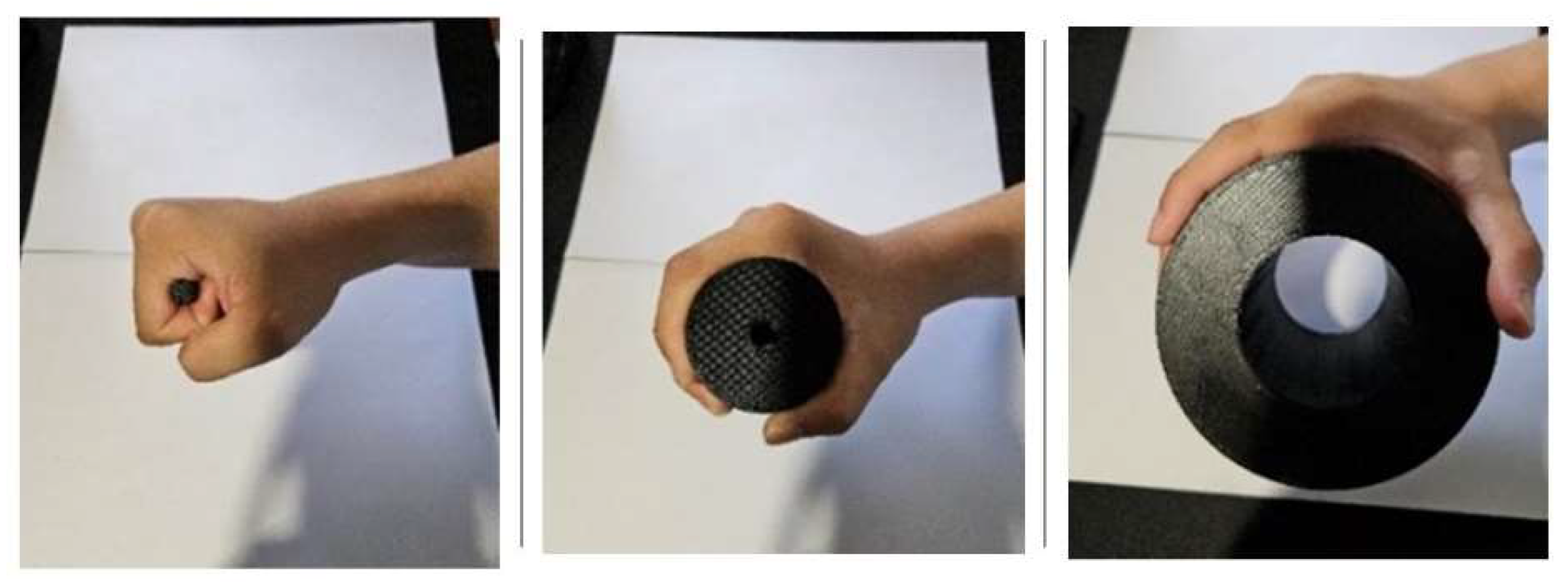
Provide the subject with cylinders of three different sizes: 10mm, 60mm, and 120mm, as shown in
Figure 3 and
Figure 4. These cylinders are used to assess flexion angles at the DIP, PIP, and MCP joints.
Capture images of the subject holding the cylinders, maintaining consistent hand positions across different cylinder sizes.
On the digital or physical copies, draw lines parallel to the top of the fingers, connecting MCP to PIP, PIP to DIP, and DIP to the fingertips. This visual aid assists in accurately visualizing the flexion angles.
Measure the angles between each drawn line by placing a protractor on top of the copies. Record the measured angle values in a tabulated form. This data serves as the basis for the final design implementation in subsequent steps.
2.5. Finger Mechanism
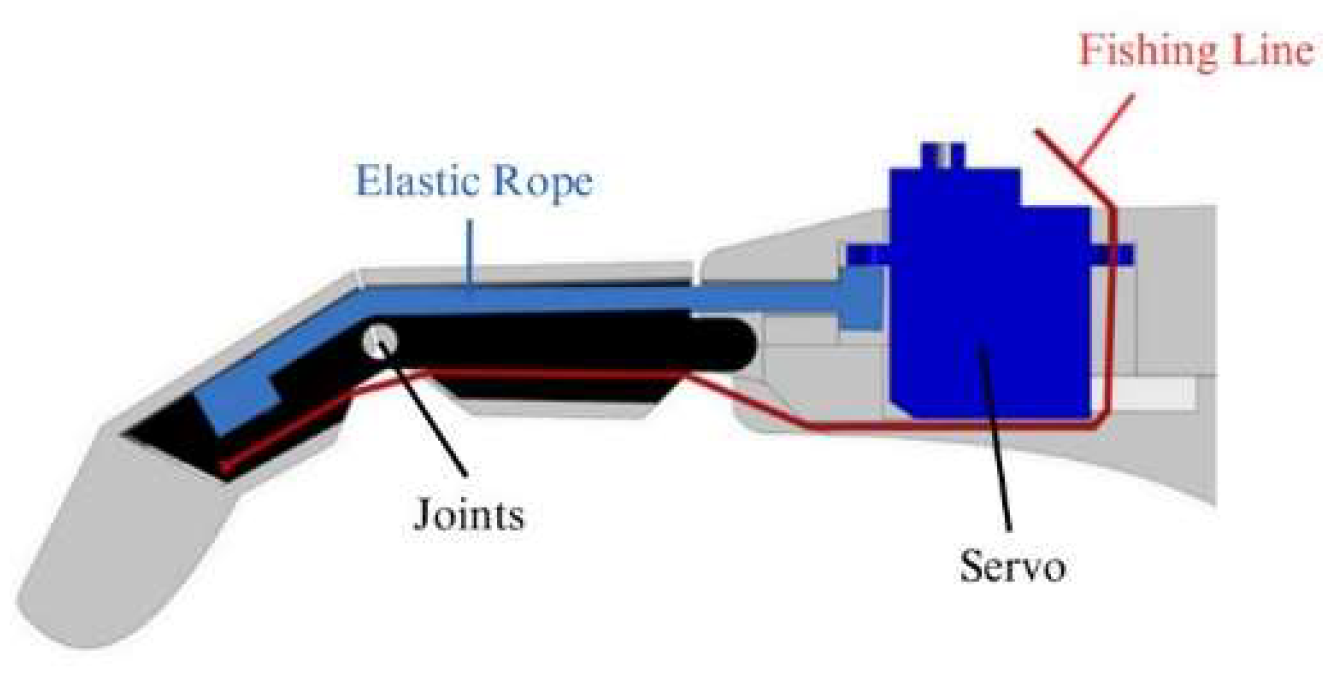
The finger mechanism of the prosthetic arm incorporates an innovative design utilizing fishing lines and elastic rope as tendons, mimicking the natural movement of human fingers, as shown in
Figure 5. The mechanism consists of a series of interconnected joints and segments, each controlled by a combination of fishing line and elastic rope using a servo motor. As the user initiates movement commands through sensors or manual controls, tension is applied to the fishing line and the elastic rope, causing the joints to flex or extend accordingly.
The fishing line serves as the primary actuator, transmitting mechanical force from the user's input to the individual finger segments. Its high tensile strength and low stretch properties ensure precise and responsive movement, enabling the prosthetic fingers to perform a wide range of gripping and grasping motions with accuracy and dexterity. Additionally, the fishing line's durability and resistance to wear make it well-suited for long-term use in prosthetic applications, providing reliable performance and longevity.
Complementing the fishing line, elastic rope acts as a passive element within the finger mechanism, providing flexibility and resilience to the system. By incorporating elastic elements into the tendon system, the prosthetic fingers can exert variable levels of force and adapt to different gripping tasks, enhancing versatility and grip stability. Furthermore, the elastic properties of the rope contribute to the natural feel and compliance of the prosthetic fingers, mimicking the spring-like behavior of biological tendons and enhancing user comfort and control.
2.6. Final Design
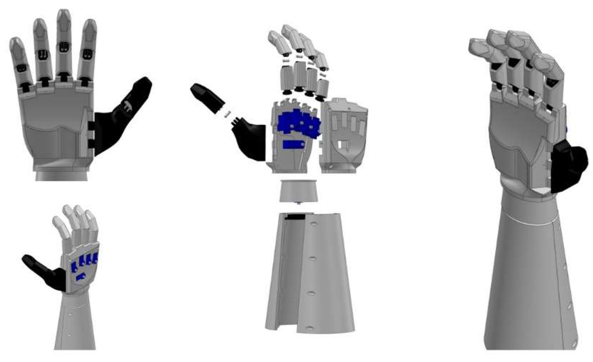
The final design of the prosthetic arm is done using 3D Computer-Aided Design (CAD) software, SolidWorks. Each component's design and assembly are also done in SolidWorks, as shown in
Figure 6. This includes all the fingers, palms, wrists, forearms, and even the joints within those fingers. The Hand of the Final Design is intelligently divided into two parts to facilitate the easy placement of the Metacarpophalangeal (MCP) joints for each finger. This division ensures precise alignment and attachment of the MCP joints to the end of the palm, optimizing finger movement and functionality.
2.7. 3D-Printing and Fabrication Process
The 3D Printing stage involves the digital model being sliced into layers and transferred to the 3D printer, which builds up the physical object layer by layer. Then, the post-processing stage involves printed components that may undergo sanding, smoothing, or painting to improve surface finish and functionality. Finally, the testing and adjustment stages involve the prosthetic arm being tested for functionality, fit, range of motion, durability, and comfort. For assembly stages, the components are assembled according to design specifications, including attaching joints, hinges, and electronic components. Once assembled, the prosthetic arm is finalized and prepared for comparison with the human hand in the subsequent experimental procedure. Any necessary adjustments or modifications are made to optimize performance and user experience. This may involve attaching joints, hinges, or other moving parts, as well as integrating any electronic components such as EMG sensors and actuators. The completed final 3D printing prosthesis arm and its assembly of the system as shown in
Figure 7.
The EMG sensors detect the electrical activity in the arm muscles, allowing the servo motors to move the prosthetic arm according to the user's muscle movements. An Arduino is used to control these servo motors and process the data from the EMG sensors. EMG control algorithms measure myoelectric signals from specific forearm muscles. The device's actuators and servo motors are controlled using these EMG signals. When the EMG signals exceed set thresholds, specific commands are executed. This system captured signals from the forearm muscles to perform actions like closing fingers or rotating joints. It enables users to control grip patterns and wrist or elbow movements, but only one action can be performed at a time.
2.8. Experiment Procedure
In this experiment, the procedure for measuring flexion angles mirrors the methodology outlined in section 2.3, where flexion angles of the human hand were assessed. The experiment focuses on manually controlling the flexion of the prosthetic finger, with the prosthetic arm serving as the subject and undergoing necessary modifications to accommodate the artificial limb. Flexion is induced by manually manipulating the control unit. This setup enables a direct comparison of flexion capabilities between the human hand and the prosthetic arm under different control mechanisms, offering valuable insights into the performance and usability of the prosthetic arm.
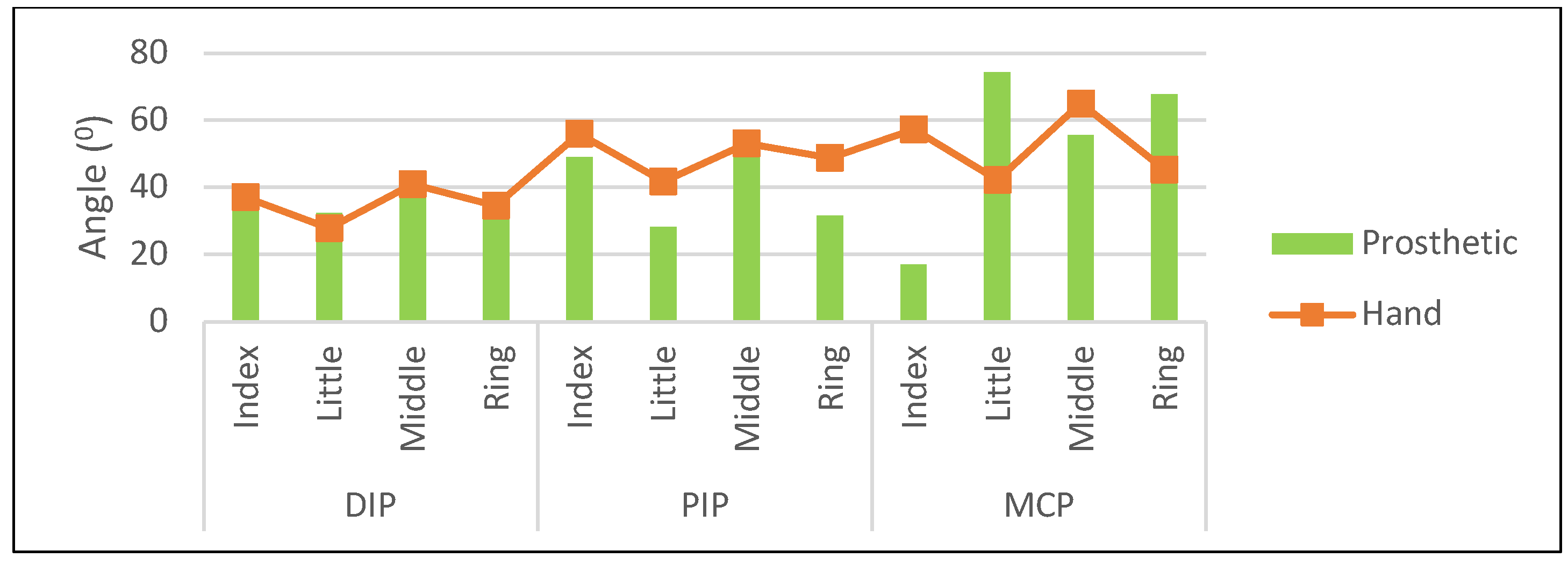
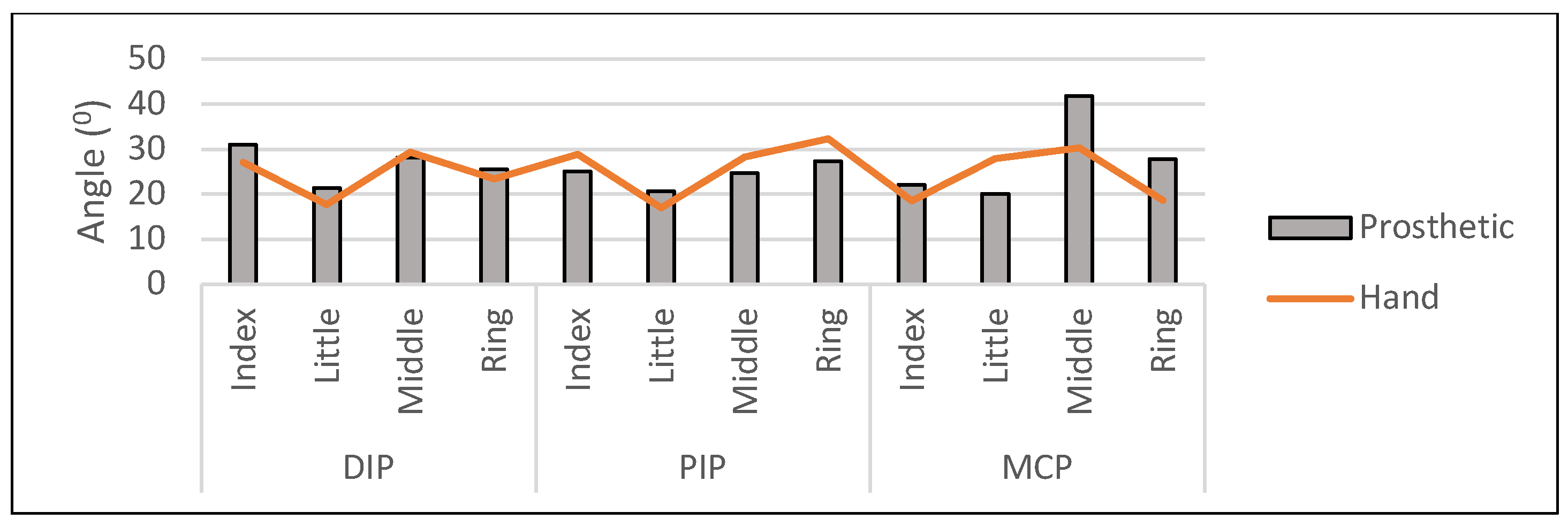
The experiment is to demonstrate the difference between the finger flexion angle of the fingers of the hand and prosthetic with the use of 3 graphs to illustrate this difference, the 10mm, 60mm, and 120mm diameters as shown in
Figure 8. The use of different diameters allows for a comprehensive analysis of the finger flexion angle across a range of sizes. This helps to evaluate the performance and adaptability of the prosthetic arm in various situations, such as grasping objects of various sizes. Comparing the flexion angles at different diameters, it provides valuable insights into the prosthetic arm's versatility and potential areas for improvement.
3. Results and Discussions
The experimental results show impressive parallels between the prosthesis arm and a real hand in terms of finger flexion angles, as shown in
Figure 9,
Figure 10 and
Figure 11. These studies demonstrate how well the prosthesis design replicates natural hand movements and capabilities. However, some substantial variations in particular joints were discovered. These inconsistencies could be attributable to human error during the photo-taking process or incorrect placement during the marking process. Refining measurement techniques to enhance accuracy and consistency in future investigations is an area for improvement. Several issues were encountered during the project, complicating the development process. One notable challenge occurred from 3D printing, where prints occasionally halted midway due to power outages, necessitating a restart of the printing process. This interruption resulted in wasted material and time. These lines could be sanded down to improve the aesthetics of the final product.
Another significant challenge was the malfunction of the prosthesis arm's control system, impacting its functionality and leading to disruptions in the testing and evaluation processes. Despite prior successful testing, the malfunction emerged unexpectedly towards the end of the project timeline, causing the prosthesis arm to cease functioning as intended. Initial assessments pointed towards potential issues with the motor components or an insufficient power supply, causing the servo motor to operate below full capacity. This setback prompted a thorough investigation, necessitating additional troubleshooting and diagnostic procedures to identify and rectify the underlying issue.
Table 4 shows the mean flexion angle of both the left and right hand. By averaging the left and right-hand values, the mean flexion angle of each finger joint between the index and little finger when gripping cylinders of different diameters can be obtained.
Additionally, the absence of a rubbery grip in the prosthesis arm highlights a potential avenue for enhancing tactile feedback and grip stability, warranting further investigation in future design iterations.
Table 5 indicates a significant increase in the flexion angles of all joints across the four fingers as the cylinder diameter decreases.
4. Conclusions
The design and fabrication of the prosthesis arm represent significant achievements. Despite unforeseen malfunctions, diligent troubleshooting allowed the arm to function successfully, achieving the objectives of designing a prosthesis for use in arm finger open and close rehabilitation. Several objectives were accomplished, including creating the prosthesis arm using 3D CAD software and additive manufacturing technology. This project provides valuable insights for future endeavors, highlighting the importance of robust testing procedures, contingency planning, and resource management in the development of assistive technologies. The results demonstrate that the prosthesis can be used in automated control rehabilitation in future projects.
To enhance future designs, it is recommended to utilize rubber-type or flexible filaments to boost strength, durability, and comfort. Investigating methods to integrate EMG sensory feedback systems into 3D-printed prosthesis arms for automated rehabilitation purposes will enable users to receive tactile feedback and better interact with their environment. Additionally, continuously refining prosthesis arm designs for improved grip strength, articulation, and range of motion in arm rehabilitation will further enhance their effectiveness and user experience.
Author Contributions
The individual contributions of the authors are as follows: I. Zunaidi: Conceptualization, Methodology, Design, Analysis, Validation, Writing- Final Draft Preparation, Review and Editing, and Supervision; Y. Rahayu and Maziri Morsidi: Evaluation, Review, Examiner; A. Elaklouk: Software and Programming; P. Hamizan: Concept, Design, Draft Preparation, Fabrication, and Data Curation.
Funding
No funding involved.
Data Availability Statement
The data that support the findings of this study are available to the corresponding author upon reasonable request.
Acknowledgments
The author(s) would like to thank Universiti Teknologi Brunei, especially the Wellness Research Center for supporting this research.
Conflicts of Interest
The authors declare that there is no conflict of interest regarding the publication of this paper.
References
- Ibrahim, Z.; Nagarajan, R.; Rizon, M.; Hazry, D.; Ruslizam, D.; Azlin, C.O. Electromyography Signal Based for Intelligent Prosthesis Design. 4th International Conference on Biomedical Engineering 2008, Kuala Lumpur, Proceedings on International Conference on Biomedical Engineering, 2008, 01.
- Zunaidi, I.; Wan, Z.; Tarmizi, I.; Shahriman, A.B. Pattern Behavior of Electromyography Signal During Arm Movements. Australian Journal of Basic and Applied Sciences 2014, 8, 714–719. [Google Scholar]
- Ziegler-Graham, K.; MacKenzie, E.J.; Ephraim, P.L.; Travison, T.G.; Brookmeyer, R. Estimating the Prevalence of Limb Loss in the United States: 2005 to 2050. Arch Phys Med Rehabil 2008, 89, 422–429. [Google Scholar] [CrossRef] [PubMed]
- Funada, K.; Wu, J.; Takahashi, S. Surface EMG and upper-limb rehabilitation. In Early Detection and Rehabilitation Technologies for Dementia: Neuroscience and Biomedical Applications; IGI Global, 2011; pp. 335–343. [Google Scholar]
- Ibrahim, Z.; Cahyadi, B.N. Utilizing Non-Immersive Virtual Reality Games for Effective Upper Limb Rehabilitation Using a Trajectory-based Analysis. The 5th International Conference on Sustainable Innovation in Engineering and Technology (SIET), 16th August 2023, IOP Conference Proceeding.
- Ikram, K.; Khairunizam, W.; Aziz, A.A.; Zunaidi, I.; Bakar, S.A.; Razlan, Z.M.; Nor, R.M.; Mustafa, W.A. Ontological Approach on Designing Knowledge Domain Presentation of MOCAP based on Arm Movement. 2018 International Conference on Intelligent Informatics and Biomedical Sciences (ICIIBMS); 10/2018.
- Cahyadi, B.N.; Khairunizam, W.; Zunaidi, I.; Ling, L.H.; Shahriman, A.B.; Zuradzman, M.R.; Mustafa, W.A.; Noriman, N.Z. Muscle Fatigue Detections During Arm Movement using EMG Signal. IOP Conference Series Materials Science and Engineering 06/2019; 557:012004.
- Ismail, N.H.; Khairunizam, W.; Majid, S.; Cahyadi, B.N.; Rudzuan, M.N.; Zunaidi, I.; Shahriman, A.B.; Zuradzman, M.R.; Mustafa, W.A. Investigation of upper arm muscle activation for the progress monitoring in stroke rehabilitation. 4th Electronic and Green Materials International Conference 2018 (EGM 2018); 12/2018.
- Cahyadi, B.N.; Khairunizam, W.; Muhammad, M.N.; Zunaidi, I.; Majid, S.H.; Rudzuan M., N; Bakar, S.A.; Razlan, Z.M.; Mustafa, W.A. Analysis of EMG based Arm Movement Sequence using Mean and Median Frequency. 2018 5th International Conference on Electrical Engineering, Computer Science and Informatics (EECSI); 10/2018.
- Abdullah, N.; Ibrahim, Z.; Ramesh, S.; Muhammad, M.A.; Ya’Akub, S.R.; Hamid, M.Z.B.S.A. Design and Simulation of Low-Cost Lower Limb Exoskeleton for Rehabilitation Exercise. 2023, AIP Conference Proceedings, (2643), 50005.
- Kiat, J.O.Y.; Ibrahim, Z.; Muhammad, M.A.; Ya’Akub, S.R.; Ali, M.Y.; Hamid, M.Z.B.S.A. Design and Fabrication of a Low-Cost Upper Limb Rehabilitation Device for Post-Stroke Patients. 2023, AIP Conference Proceedings, (2643), 50007.
- Zunaidi, I.; Hamizan, S.K.; Azlan, A.; Maziri, M.; Shamil, R.; Malai, H.Z. Design and Development of an Advanced Upper Limb Rehabilitation Robot for Post-Stroke Rehabilitation. Proceedings of the 2023 6th IEEE International Conference on Applied Computational Intelligence in Information Systems, ACIIS 2023, 2023, 10.
- Dusseiller, M.R.; Schlaepfer, D.; Koch, M.; Kroschewski, R.; Textor, M. An inverted microcontact printing method on topographically structured polystyrene chips for arrayed micro-3-D culturing of single cells. Biomaterials 2005, 26, 5917–5925. [Google Scholar] [CrossRef] [PubMed]
- Ali, A.S.; Ibrahim, Z.; Aziz, A.; Ali, M.Y. An Electromyography Signal Enhancement for Upper Limb Rehabilitation Robot Manipulator. The 5th International Conference on Sustainable Innovation in Engineering and Technology (SIET), 16th August 2023, IOP Conference Proceeding.
- Sheikh, A.T.; Pereira, K.P.S.; Gopalakrishna, B.K.; Raju, K. Design and fabrication of automated prosthetic arm. Mangaluru, India: AIP, May 2020, p. 070003.
- Fulzele, A.; Kocha, H.; Jain, A.; Sawant, D.; Raut, A. 3D Printed Prosthetic Arm. in 2020 IEEE 15th International Conference on Industrial and Information Systems (ICIIS), India, Nov. 2020, pp. 109–114.
- Selvan, M.P.; Raj, R.; Sai, R.G.; Jancy, S.; Mary, V.A. Prosthetic Hand Using Emg. J Phys Conf Ser 2021, 1770, 012018. [Google Scholar] [CrossRef]
- Tenore, F.; Ramos, A.; Fahmy, A.; Acharya, S.; Etienne-Cummings, R.; Thakor, N.V. Towards the Control of Individual Fingers of a Prosthetic Hand Using Surface EMG Signals. in 2007 29th Annual International Conference of the IEEE Engineering in Medicine and Biology Society, Lyon, France: IEEE, Aug. 2007, pp. 6145–6148.
- Venkatesh, B.; et al. Design and Development of Wireless Operated Low Cost Prosthetic Hand by Fused Deposition Modeling. International Journal of Mechanical and Production Engineering Research and Development 2018, 8, 393–398. [Google Scholar]
- Gretsch, K.F.; et al. Development of novel 3D-printed robotic prosthetic for transradial amputees. Prosthet Orthot Int 2016, 40, 400–403. [Google Scholar] [CrossRef] [PubMed]
- Bahari, M.S.; Jaffar, A.; Low, C.Y.; Jaafar, R.; Roese, K.; Yussof, H. Design and Development of a Multifingered Prosthetic Hand. Int J Soc Robot 2012, 4, 59–66. [Google Scholar] [CrossRef]
- Sivaraman, P.; et al. Humanoid gesture control ARM with manifold actuation by embedded system. Mater Today Proc 2021, 37, 2749–2758. [Google Scholar] [CrossRef]
- Wan, K.; Ikram, K.; Halim, H.; Aziz, A.; Zunaidi, I.; Bakar, S.A.; Mustafa, W.A.W. Analysis of attribute domain for geometrical gesture performed by arm movements. Indonesian Journal of Electrical Engineering and Computer Science 2019, 16. [Google Scholar]
- Swetha, R.; NirmalaDevi, S. Design of Prosthetic Arm. Advances in Parallel Computing 2021, 38, 73–80. [Google Scholar]
|
Disclaimer/Publisher’s Note: The statements, opinions and data contained in all publications are solely those of the individual author(s) and contributor(s) and not of MDPI and/or the editor(s). MDPI and/or the editor(s) disclaim responsibility for any injury to people or property resulting from any ideas, methods, instructions or products referred to in the content. |
© 2024 by the authors. Licensee MDPI, Basel, Switzerland. This article is an open access article distributed under the terms and conditions of the Creative Commons Attribution (CC BY) license (http://creativecommons.org/licenses/by/4.0/).
