Preprint
Article

State of Charge Balancing Control Strategy for Wind Power Hybrid Energy Storage Based on Successive Variational Mode Decomposition and Multi-Fuzzy Control

This version is not peer-reviewed.

Submitted:

15 October 2024

Posted:

16 October 2024

You are already at the latest version

A peer-reviewed article of this preprint also exists.

Abstract
To address the instability of wind power caused by the randomness and intermittency of wind generation, as well as the challenges in power compensation by Hybrid Energy Storage Systems (HESS), this paper proposes a State of Charge (SOC) balancing control strategy based on Successive Variational Mode Decomposition and multi-fuzzy control. First, a consensus algorithm is used to enable communication between energy storage units to obtain the global average SOC. Then, the Secretary Bird Optimization Algorithm (SBOA) is applied to optimize the Successive Variational Mode Decomposition (SVMD) and Variational Mode Decomposition (VMD) for the initial allocation of wind power, resulting in the smoothing power for hybrid energy storage and the grid integration power. Finally, considering the deviation between the current SOC of the storage units and the global average SOC, dynamic partitioning is used for multi-fuzzy control to adjust the initial power allocation, achieving SOC balancing control. Simulations of the control strategy were conducted using Matlab/Simulink, and the results indicate that the proposed approach effectively smooths wind power fluctuations, achieving stable grid integration power. It enables the SOC of the HESS to quickly align with the global average SOC, preventing the HESS from entering unhealthy SOC regions.
Keywords: 
Subject: 
Engineering  -   Electrical and Electronic Engineering

1. Introduction

Traditional power generation primarily relies on fossil fuels, which release large amounts of greenhouse gases when burned, exacerbating the issue of global warming. At the same time, the depletion of fossil fuels has led to a steady increase in prices [1]. Utilizing renewable energy for distributed generation offers significant economic and environmental benefits, making it a highly viable solution [2]. Wind energy, as an emerging renewable resource with relatively mature technology, has become a promising method of renewable energy generation and plays a key role in promoting the sustainable development of global energy [3].
With the widespread adoption of wind power globally, its penetration into the grid continues to increase, posing significant threats to the stability and security of the power grid due to its randomness, volatility, and intermittency [4,5,6]. To address this challenge, HESS offers a solution by smoothing complex wind power fluctuations to enhance the stability of grid integration [7,8]. Due to the varying functions of energy storage devices, battery storage, which is energy-based, offers high energy density and shorter cycle life, making it suitable for low-frequency power fluctuations. In contrast, supercapacitor storage, which is power-based, features high power density and longer cycle life, with strong environmental benefits. It can suppress high-frequency power fluctuations and reduce batteries’ charge and discharge cycles, thereby extending their lifespan [9,10,11]. The application of hybrid energy storage systems in microgrids achieves complementary advantages, leading to energy management issues among different storage units. It is essential to allocate real-time power effectively to utilize each storage unit’s unique functional characteristics, representing both a future direction and a challenge.
Energy storage in microgrids is shifting from traditional centralized systems to more flexible and efficient distributed storage. Distributed energy storage is scattered across various renewable energy generation sources and critical loads, enabling units with similar functions to achieve collective autonomy and coordinated management. This is significant for enhancing the overall performance of microgrids. A key issue in this context is how to ensure that the SOC of each storage unit remains consistent. Otherwise, the imbalance of the SOC among storage units may cause some units to enter protection mode due to the risk of overcharging or discharging, increasing the burden on other units and hindering the efficient operation of the energy storage group. From the perspective of the control structure of distributed hybrid energy storage energy management systems, they can be classified into centralized control, decentralized control, and distributed control [12,13,14,15,16]. Centralized control consists of a central controller and local controllers. As the number of distributed power sources increases, there is a greater demand for the central controller to have strong computational capabilities. This reliance on the central controller can lead to issues such as a single point of failure and a curse of dimensionality in the system [13,14]. In a decentralized control system, each control unit operates independently and makes decisions based on local information, with no direct communication or collaboration between units. Since each unit optimizes only based on local data, this can lead to globally suboptimal solutions and lower overall system efficiency [15]. Distributed control only requires ’neighbor communication’ to obtain global information. Through cooperation among intelligent agents, tasks are accomplished, enhancing system efficiency and reliability while reducing communication costs and delays. Multi-agent distributed control offers advantages such as autonomous decision-making and coordinated control. Compared to traditional centralized control, it significantly lowers communication costs and improves system efficiency, making it increasingly applicable in microgrids [16].
The application of hybrid energy storage systems in microgrids achieves complementary advantages but also creates energy management challenges among different storage units. Therefore, it is necessary to allocate smoothing power based on the characteristics of each storage component to suit the features of hybrid storage. This approach maximizes their effectiveness while extending their lifespan, which is essential for the initial power allocation in hybrid storage systems. Due to variations in factors such as the initial SOC of the storage units, the precision of manufacturing processes, and the degree of aging, the imbalance in SOC among different storage units can lead to some units entering protection mode due to the risk of overcharging or discharging. This increases the burden on other units and hinders the efficient operation of the energy storage group. Therefore, it is necessary to adjust the reference power for hybrid storage to prevent overutilization and underutilization of the storage devices. This adjustment process constitutes the secondary allocation in hybrid energy storage [17]. Reference [18] uses a Low-Pass Filter (LPF) for the initial power allocation of HESS and employs an adaptive time constant based on the LPF to optimize the utilization of supercapacitors and the operating time of batteries, thereby enhancing their lifespan. Reference [19] employs traditional Extended Droop Control (EDC) for initial power allocation and introduces a SOC reference value to design a controller that adjusts the droop coefficient in real time, thereby achieving SOC balancing for hybrid energy storage. Reference [20] designs an LPF for initial power allocation and implements a fuzzy control system to adaptively adjust the parameters of the LPF, ensuring the adaptive regulation of the SOC in hybrid energy storage and preventing overcharging and discharging. Reference [21] employs a virtual capacitance and resistance descent method for the initial power allocation of hybrid energy storage and introduces an adaptive capacitance droop controller for supercapacitors to improve their SOC curve. Reference [22] proposes a Weighted Moving Average (WMA) filter to achieve the initial allocation of HESS. It then uses a Model Predictive Control (MPC) method to quickly adjust the SOC of HESS during the wind power smoothing process, thereby reducing battery lifespan deterioration. Since Huang introduced empirical mode decomposition, reference [23] has proposed a fully non-recursive variational mode decomposition model that reduces mode mixing and demonstrates greater robustness to noise. Although it is influenced by the number of modes K and the penalty parameter α , it offers significant advantages in power allocation.Reference [24] proposes a method for smoothing photovoltaic power fluctuations in HESS based on VMD, achieving initial power allocation. VMD can adaptively determine the grid-connected power and the smoothing power of HESS, facilitating secondary allocation and extending the lifespan of the batteries. Reference [25] proposes the use of the Artificial Hummingbird Algorithm (AHA) for parameter optimization of VMD, thereby enabling effective initial power allocation for hybrid energy storage. A fuzzy controller is employed to further optimize the initially allocated power, ensuring that the SOC of the hybrid storage remains stable within a fixed range. Reference [26] introduces SVMD based on VMD. This method eliminates the influence of the mode K parameter, requiring only the setting of a maximum parameter α to sequentially extract modes. Moreover, the computational complexity of SVMD is significantly lower than that of VMD, and it exhibits greater robustness to the initial values of the mode center frequencies. Reference [27] employs SVMD to decompose wind power and performs piecewise reconstruction of the mode functions for the initial allocation of hybrid energy storage power. "Then, an energy storage power model is established, and the target model is solved while considering the constraints of charging and discharging power and the state of charge, resulting in the optimal configuration of the hybrid energy storage system. Currently, the application of successive SVMD and VMD combined with fuzzy control in the power allocation of HESS is relatively limited. However, leveraging the advantages of both control methods may yield superior energy management outcomes when applied together in distributed hybrid energy storage systems. Furthermore, most existing studies utilize a single fuzzy controller; however, a single controller often fails to adapt to the varying power adjustment needs of hybrid energy storage systems across different periods. This limitation may result in uneven power distribution, potentially leading to issues such as overcharging and over-discharging.
In summary, to ensure the long-term power smoothing effectiveness of the wind-storage hybrid system and the reliability of battery functions, it is crucial to optimize the SOC of the HESS from an operational control perspective. This optimization involves reducing the depth of charging and discharging cycles while minimizing unnecessary charging and discharging events. Furthermore, from the perspective of maximum charging and discharging power, the energy storage units can be operated within a reasonable power range based on their parameters, enabling the distribution of wind power that meets the requirements for power smoothing. Therefore, building on existing research, this paper proposes a method that considers the goal of SOC equilibrium control by combining power modal decomposition algorithms with the optimized snake-ladybird algorithm, designing a multi-fuzzy rule-based approach for controlling the target power of energy storage. The main technical contributions of this study are as follows:
  • A method is proposed to prevent the overuse or underutilization of any specific energy storage device within the HESS, as well as to manage prioritization or gradual charging.
  • The grid-connected power optimization selection method based on SBOA-VMD effectively enhances the stability and output reliability of the grid power, ensuring the smooth operation of the power system. Utilizing the decomposition characteristics of SBOA-SVMD allows for a more precise selection of smoothing power according to the specific characteristics of each energy storage unit, thereby reducing fluctuations in grid power and improving system stability and response speed.
  • A multi-fuzzy controller is designed in partitions based on the deviation between the SOC of energy storage units and the global average SOC. This strengthens the SOC balance among storage units, preventing individual or group units from exiting operation due to overcharging or over-discharging, thereby enhancing the overall system reliability.
The structure of this paper is as follows: Section 2 introduces the system network structure model; Section 3 presents the optimization algorithm, modal decomposition algorithm, and power allocation strategy; Section 4 provides the simulation analysis; and finally, the conclusions are presented.

2. System Network Architecture Diagram

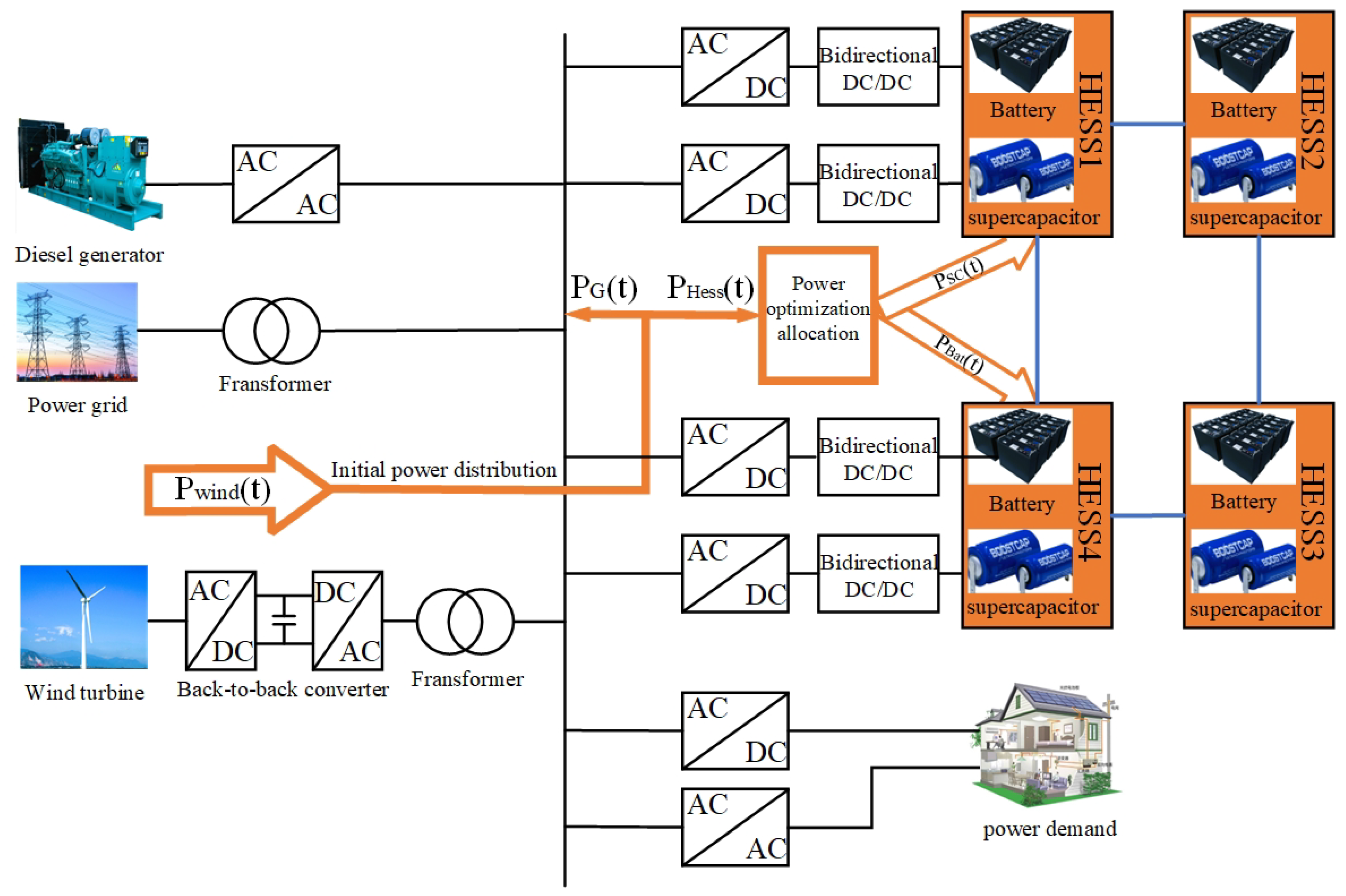
To address the randomness, volatility, and intermittency of wind power, the hybrid energy storage system is distributed along the AC bus. Their topology is shown in Figure 1. The wind power hybrid storage system consists of power electronic devices connecting the AC bus with the grid, diesel generators, wind turbines, and electrical loads.
Figure 1, P w i n d ( t ) represents the output power of the wind power generation system, while P B a t ( t ) and P S C ( t ) indicate the charging or discharging power of the lithium battery and the supercapacitor, respectively. P H e s s ( t ) is the reference output power of the hybrid energy storage system, and P G ( t ) is the grid-connected wind power after being smoothed by the hybrid energy storage system. Based on the power relationships shown in the figure, the following expressions can be established:
P w i n d ( t ) = P H e s s ( t ) + P G ( t ) P H e s s ( t ) = P B a t ( t ) + P S C ( t )

2.1. Wind Turbine Power Model

Wind turbines are affected by wind forces; the wind turbine rotor requires a certain wind speed to start rotating. However, excessive wind speeds can cause damage to the wind turbine. To protect the turbine, the wind generator will stop operating under such conditions. Therefore, the wind turbine output power can be expressed as:
P a ( t ) = 0 ( V s > V , V > V b ) 1 2 ρ π R 2 C p ( λ , β ) V 3 ( V s < V < V n ) P N ( V n < V < V b )
where P a ( t ) is the mechanical power obtained from the turbine blades; V is the actual wind speed at the turbine hub height; P s ( t ) is the turbine’s cut-in wind speed; P b ( t ) is the turbine’s cut-out wind speed; R represents the rotor radius; β is the pitch angle of the turbine blades; λ is the tip-speed ratio, which is a function of the turbine’s rotational speed; C p ( t ) represents the power coefficient of the wind turbine; V n ( t ) is the minimum wind speed for full power generation; P N ( t ) represents the rated power of the turbine under normal full-load conditions; and ρ is the local air density( k g / m 3 ).

2.2. Battery Storage Device Model

Battery storage devices are primarily used to handle the low-frequency components of power tasks in a hybrid energy storage system. However, the parameters of the battery model continuously change with variations in the SOC, cycle count, and capacity degradation. Based on these factors, the mathematical model of the battery [28] can be expressed as:
S O C B a t ( t ) = S O C B a t ( t 0 ) 1 Q n t 0 t i ( ξ ) ( δ B a t 1 , δ B a t ) d ξ
Q B a t ( t ) = Q B a t ( t 0 ) t 0 t i ( ξ ) ( δ B a t 1 , δ B a t ) d ξ
E b a t _ c h ( t ) = E 0 K · Q ( Q i t ) · i * K · Q ( Q i t ) · i t + A e B · i t
E b a t _ d i s ( t ) = E 0 K · Q ( i t + 0.1 Q ) · i * K · Q ( Q i t ) · i t + A · e B · i t
where S O C B a t ( t ) represents the SOC of the battery at time t; δ B a t 1 and δ B a t are the charge and discharge coefficients; i ( ξ ) denotes the charging and discharging current of the battery; Q n indicates the rated capacity of the battery; Q B a t represents the capacity of the battery at time t; E b a t _ c h ( t ) signifies the battery charging voltage at that moment; E b a t _ d i s ( t ) represents the battery discharging voltage at that moment; E 0 is the constant electromotive force of the battery; K is the polarization constant of the battery; Q denotes the maximum charge capacity of the battery; A refers to the exponential voltage; B indicates the exponential capacity; i t represents the amount of consumed charge; and i * is the low-frequency component of the current.

2.3. Supercapacitor Model

Supercapacitors offer advantages in energy storage systems, including fast response times, frequency regulation, and peak shaving. Additionally, their cycle life and response rate are significantly higher than those of batteries. Based on these advantages, supercapacitors are well-suited for handling the high-frequency components of power tasks in a hybrid energy storage system. The mathematical model expression is as follows:
Q S C ( t ) = Q S C ( t 0 ) t 0 t I S C ( ξ ) ( δ 1 , δ ) d ξ
S O C S C ( t ) = S O C S C ( t 0 ) 1 Q S C , n t t 0 I S C ( ξ ) ( δ 1 , δ ) d ξ
where Q s c ( t ) represents the supercapacitor capacity at time t; δ 1 and δ are the supercapacitor charging and discharging coefficients; I s c ( ξ ) is the supercapacitor charging and discharging current; S O C s c ( t ) is the state of charge of the supercapacitor at time t; and Q s c , n is the rated capacity of the supercapacitor.

2.4. Constraints

To ensure the safe operation of the wind power hybrid storage system, the battery and supercapacitor must meet the following constraints during operation. The specific formulas are as follows:
s . t 0 P B a t . d i s P B a t . d i s _ min 0 P B a t . c h P B a t . c h _ max S O C B a t . min S O C B a t ( t ) S O C B a t . max
s . t 0 P S C . d i s P S C . d i s _ min 0 P S C . c h P S C . c h _ max S O C S C . min S O C S C ( t ) S O C S C . max
where P B a t . c h _ max and P B a t . d i s _ min represent the charging and discharging power limits of the battery, respectively. P S C . c h _ max and P S C . d i s _ min represent the charging and discharging power limits of the supercapacitor, respectively. S O C B a t . min and S O C B a t . max represent the minimum and maximum state of charge limits for the lithium battery, respectively; S O C S C . min and S O C S C . max represent the minimum and maximum state of charge limits for the supercapacitor, respectively.
To address the operational characteristics of the energy storage components in a hybrid storage system, and to ensure that wind power is integrated into the grid under reasonable conditions while also achieving proper power distribution in the hybrid energy storage system and avoiding overcharging and deep discharging, this paper proposes a power distribution strategy for the wind power hybrid storage system based on dynamic consensus algorithms and multi-fuzzy control.

3. Hybrid Energy Storage Power Allocation Strategy

In the initial power allocation, successive variational mode decomposition (SVMD) extracts one modal component at a time, which can effectively reduce mode mixing and result in more independent modes, while having lower computational complexity compared to VMD. SVMD does not require prior knowledge of the number of modes; it adaptively extracts modes from the signal one by one, reducing dependence on parameter selection, and is only influenced by the maximum parameter α . variational mode decomposition (VMD) is a technique that simultaneously decomposes a signal into multiple modes. The number of modes K and the penalty parameter α significantly affect the decomposition results of VMD. When the value of K is too large, it can lead to over-decomposition, whereas if it is too small, under-decomposition occurs. Similarly, if the value of α is too high, it may result in the loss of frequency band information, while a lower value can lead to redundant information. Therefore, this paper introduces the Secretary Bird Optimization Algorithm(SBOA) to optimize the parameters of SVMD and VMD, selecting the mean envelope entropy as the fitness function. This approach determines the maximum α for SVMD and the optimal parameter pair [ k , α ] for VMD, thereby obtaining the grid-connected power and hybrid energy storage power.

3.1. Successive Variational Modal Decomposition

The superior decomposition modes of successive variational mode decomposition (SVMD) and the algorithm’s low complexity, when applied to hybrid energy storage systems, enable better allocation of power between batteries and supercapacitors, thereby extending the lifespan of the storage units.
The wind power P w i n d ( t ) during the mth decomposition of SVMD is divided into two parts: the mth mode P m ( t ) and the residual signal P r m ( t ) , where P r m ( t ) includes the undecomposed part of SVMD P u m ( t ) and the sum of modes from the 1st to the ( m 1 ) th. The formula is as follows:
P w i n d ( t ) = P m ( t ) + P r m ( t )
P r m ( t ) = k = 1 m 1 P k ( t ) + P u m ( t )
During the SVMD decomposition process, each mode should remain compact around its central frequency, while minimizing mode aliasing between P m ( t ) and P r m ( t ) . The constraint conditions to meet this requirement are as follows:
M 1 = t ( δ ( t ) + j π t ) P m ( t ) e j ω h t 2 2
M 2 = k = 1 m 1 P m ( ω ) α ( ω ω k ) 2 2 2
M 3 = P r m ( ω ) α ( ω ω m ) 2 2 2
The establishment of the Lagrange function ensures the algorithm’s robustness against interference and the fidelity of signal decomposition, which includes a combination of the quadratic penalty term α and the Lagrange multiplier λ . The formulation is as follows:
L ( P m , ω m , λ ) = min α M 1 + M 2 + M 3 + P w i n d ( t ) ( P m ( t ) + P u m ( t ) + k = 1 m 1 P k ( t ) ) 2 2 + λ ( t ) , P w i n d ( t ) P m ( t ) + P u m ( t ) + k = 1 m 1 P k ( t )
SVMD transforms an m-dimensional problem into m-one-dimensional optimization problems, thereby reducing the number of iterations and saving time.

3.2. Variational Modal Decomposition

Although the successive variational mode decomposition (SVMD) achieves better decomposition results, each modal power frequency range is relatively wide, which does not meet the requirements for grid connection power. In contrast, the variational mode decomposition (VMD) generates modal combinations with frequencies below 10 3 H z , from which modes that satisfy grid connection standards are selected for integration into the grid into the grid.
min { u k } , { ω k } = k | | t [ ( δ ( t ) + j π t ) * u k ( t ) ] e j ω k t | | 2 2 s . t . k = 1 k u k = f ( t )
where k represents the number of decomposition modes; u k denotes the sum of all mode functions; ω k represents the set of their center frequencies; denotes the derivative concerning time; δ ( t ) is the dirichlet distribution function; * is the convolution operator; | | | | 2 2 denotes the squared gradient norm; f ( t ) is the original signal to be decomposed.
By introducing a secondary penalty factor α and a lagrange multiplier λ ( t ) Equation (17) is transformed into an equivalent unconstrained variational problem, which is then solved using the alternating direction method of multipliers to obtain the optimal solution. The expression is as follows:
u ^ k n + 1 ( ω ) = f ^ ( ω ) i k u ^ i ( ω ) + λ ^ ( ω ) 2 1 + 2 a ( ω ω k ) 2
ω k n + 1 = 0 ω | u ^ k ( ω ) | 2 d ω 0 | u ^ k ( ω ) | 2 d ω
λ ^ n + 1 ( ω ) = λ ^ n ( ω ) + τ [ f ^ ( ω ) k = 1 k u ^ k n + 1 ( ω ) ]
where n represents the number of iterations; u ^ k n + 1 ( ω ) represents the frequency domain of the kth modal component after updating; ω k n + 1 denotes the updated frequency of the kth modal component; τ is the step size, with τ > 0 .

3.3. Principles of the Secretary Bird Optimization Algorithm

The Secretary Bird Optimization Algorithm (SBOA), introduced in 2024, is a novel swarm optimization technique that models the hunting and escaping behaviors of secretary birds in two distinct stages. During these stages, each member of the secretary bird group is updated accordingly. The hunting behavior is generally divided into three processes: searching for prey, attacking prey, and consuming prey. Meanwhile, escaping behavior is classified into two types: environmental camouflage and rapid movement, such as flying or running swiftly.
The first stage involves the secretary bird’s hunting strategy (exploration phase), where the hunting process is divided into three equal time intervals. This approach enhances the algorithm’s diversity and global search ability. The position update formula for this first stage is provided below:
X i , j n e w , P 1 = X i , j + ( X r a n d o m _ 1 X r a n d o m _ 2 ) × R 1 ( t < 1 3 T ) X b e s t + e ( t T ) 4 × ( RB 0.5 ) × ( X b e s t X i , j ) ( 1 3 T < t < 2 3 T ) X b e s t + ( 1 t T ) 2 × t T × X i , j × RL ( t > 2 3 T )
X i = X i n e w , P 1 ( F i n e w , P 1 < F i ) X i else
R B = r a n d n ( 1 , j )
R L = 0.5 × s × u × σ | ν | 1 η
σ = Γ ( 1 + η ) × sin ( π η 2 ) Γ ( 1 + η 2 ) × η × 2 ( η 1 2 ) 1 η
where j represents the dimension of the variable; X denotes the positions of the secretary bird group; X i indicates the position of the ith secretary bird; X i , j represents the value of a variable for the ith secretary bird in the jth dimension; X i , j n e w , P 1 denotes the new position of the ith secretary bird in the jth dimension during the first stage; X r a n d o m _ 1 and X r a n d o m _ 2 are random candidate solutions during the iteration; X b e s t is the best historical position of the secretary bird; R 1 represents an array with dimensions 1 × j randomly generated in the interval [0,1]; F i represents the objective function value obtained by the ith secretary bird, and F i n e w , P 1 represents the new objective function value obtained by the ith secretary bird; t and T represent the current iteration count and the maximum iteration count, respectively; RB is a 1 × j dimensional array randomly generated from the standard normal distribution; RL indicates the Levy flight strategy, where s = 0.01 and η = 1.5 ; μ and ν are random numbers within the interval [0,1]; Γ denotes the gamma function.
The second stage is the secretary bird’s escaping strategy (exploitation phase), where both escaping strategies can be represented by Equation (25). The position update formula for the second stage is shown below:
X i , j n e w , P 2 = X b e s t + ( 2 × R B 1 ) × ( 1 t T ) 2 × X i , j ( r < 0 . 5 ) X i , j + R 2 × ( X r a n d o m K × X i , j ) else
X i = X i n e w , P 2 ( F i n e w , P 2 < F i ) X i else
K = r o u n d ( 1 + r a n d ( 1 , 1 ) )
where X i , j n e w , P 2 represents the new position of the ith secretary bird in the jth dimension during the second stage; F i n e w , P 2 represents the new objective function value obtained by the ith secretary bird during the second stage; R 2 denotes an array of dimension 1 × j randomly generated from a normal distribution; X r a n d o m represents the random candidate solution for the current iteration; K denotes a random value of either 1 or 2; r a n d ( 1 , 1 ) is a random number generated between 0 and 1.

3.3.1. SBOA-Optimized VMD and SVMD Algorithm

When the SBOA algorithm searches for the optimal parameters for SVMD and VMD decomposition, it is necessary to define a fitness function to evaluate whether the selected parameters are optimal. The quality of the chosen fitness function significantly impacts the effectiveness of the SBOA in parameter selection. The average envelope entropy can effectively evaluate the quality of decomposition, filter useful modes, and capture the nonlinear characteristics of the signal, thereby helping to improve the decomposition performance of the wind power signal. The calculation method for average envelope entropy is as follows:
< k ^ , α ^ > = arg min ( k , α ) 1 k ^ i = 1 k ^ E p ( i )
E p ( i ) = i = 1 N p i lg p i
p i = a ( i ) i N a ( i )
where k ^ and α ^ represent the optimal combination; E p ( i ) is the envelope entropy of each modal component after Hilbert demodulation; i denotes the number of sampling points; p i is the normalized form of a ( i ) ; a ( i ) represents the envelope signal.
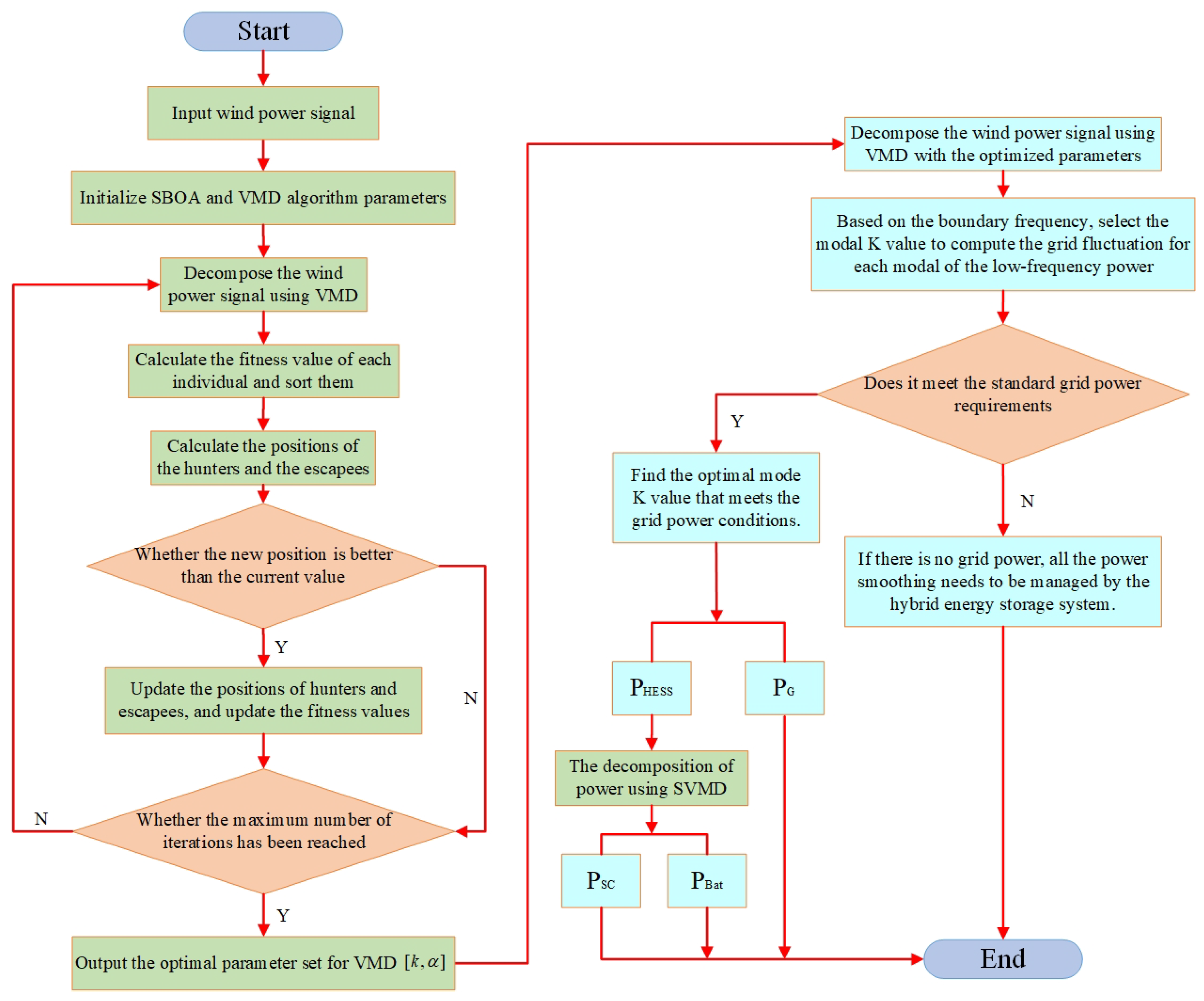
This study selects the average envelope entropy as the fitness function, with the minimum value of the average envelope entropy as the optimization objective. This approach results in obtaining the optimal parameters for [ k , α ] as well as the maximum parameter α . Based on the optimal parameters, the original signal is decomposed, with the boundary frequency for the energy storage units set at 10 3 H z . This meets the requirement that the 10-minute grid-connected fluctuation amount is typically 5 % to 7.5 % of the installed wind power capacity. The flowchart for the initial power distribution strategy of wind power is shown in the figure below:
Figure 2. Flowchart of the initial power allocation using VMD and SVMD.
Preprints 121342 g002

3.4. Hybrid Energy Storage Multi-Fuzzy Control Power Secondary Distribution Strategy

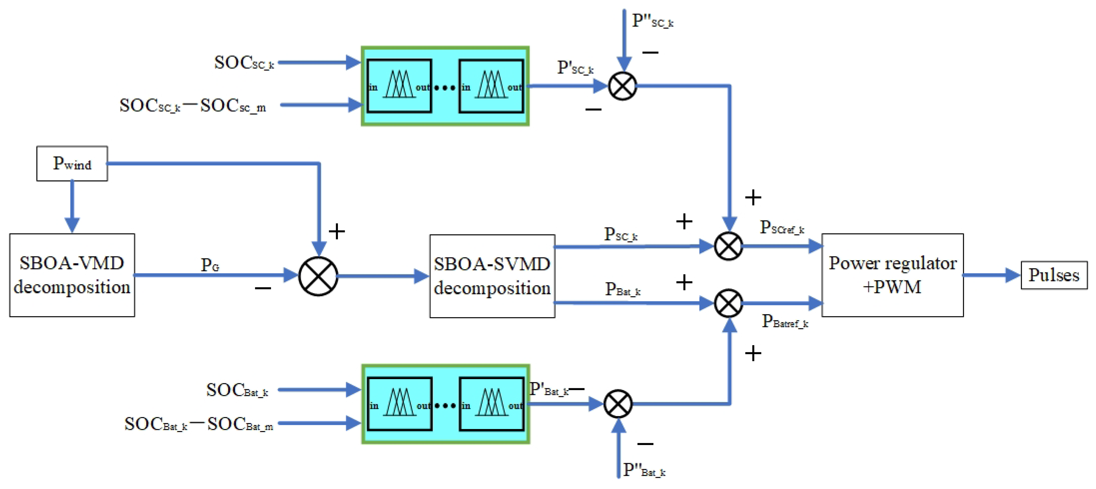
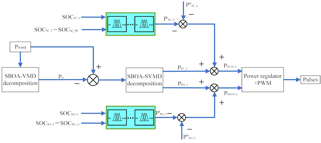
Due to differences in installed capacity, aging progress, and manufacturing processes, the initial state of charge (SOC) and capacity of hybrid energy storage systems (HESS) often vary from one another. If the discharge rate of the hybrid energy storage system (HESS) varies during the discharge process, HESS units with lower states of charge (SOC) will complete their discharge first. This inconsistency can reduce the capacity utilization and lifespan of the HESS. Therefore, balancing the state of charge (SOC) of a non-isolated hybrid energy storage system (HESS) is crucial. In the secondary power distribution process, HESS units with higher SOC will output more power or absorb less, while those with lower SOC will absorb more power or output less. This approach ensures that the HESS operates within its normal working range. The control structure diagram is shown in Figure 3.
Figure 4, P w i n d represents the wind power signal; P G denotes the grid-connected power; S O C S C _ k and S O C B a t _ k indicate the SOC states of the kth supercapacitor and battery, respectively; S O C S C _ m and S O C B a t _ m represent the average SOC of the supercapacitor and battery group; P S C _ k and P B a t _ k denote the smoothing power of the kth supercapacitor and battery; P S C _ k and P S C _ k illustrate the power adjustment by the fuzzy control for the supercapacitor and its actual power; P B a t _ k and P B a t _ k depict the power adjustment by the fuzzy control for the battery and its actual power; P S C r e f _ k and P B a t r e f _ k represent the reference power of the kth supercapacitor and battery, respectively. The power regulator and PWM controller generate pulse signals to control the three-phase inverter, which regulates the power output of the energy storage units. Each energy storage unit is analogous to an individual agent, which communicates through equations (32) and (33) to obtain the global average state of charge (SOC).
S O C i ( k + 1 ) = Z i ( k ) + α j N i ψ i j ( k + 1 )
ψ i j ( k + 1 ) = ψ i j ( k ) + S O C j ( k ) S O C i ( k )
where k represents the number of iterations; Z i denotes the initial state of charge (SOC) for the ith agent, with S O C i ( 0 ) = Z i and ψ i j ( 0 ) = 0 ; N i refers to the ith energy storage unit agent; and ψ i j indicates the cumulative variable between the ith agent and the jth agent. If an energy storage unit leaves the system or if the communication within the storage units changes, the new system will still converge to the average value of the current number of energy storage units. This algorithm distributes the leader’s role evenly among all energy storage units, ensuring that the algorithm does not fail due to the loss of a single energy storage unit. Ultimately, the energy storage system achieves the collective average state of charge (SOC) of the storage units.
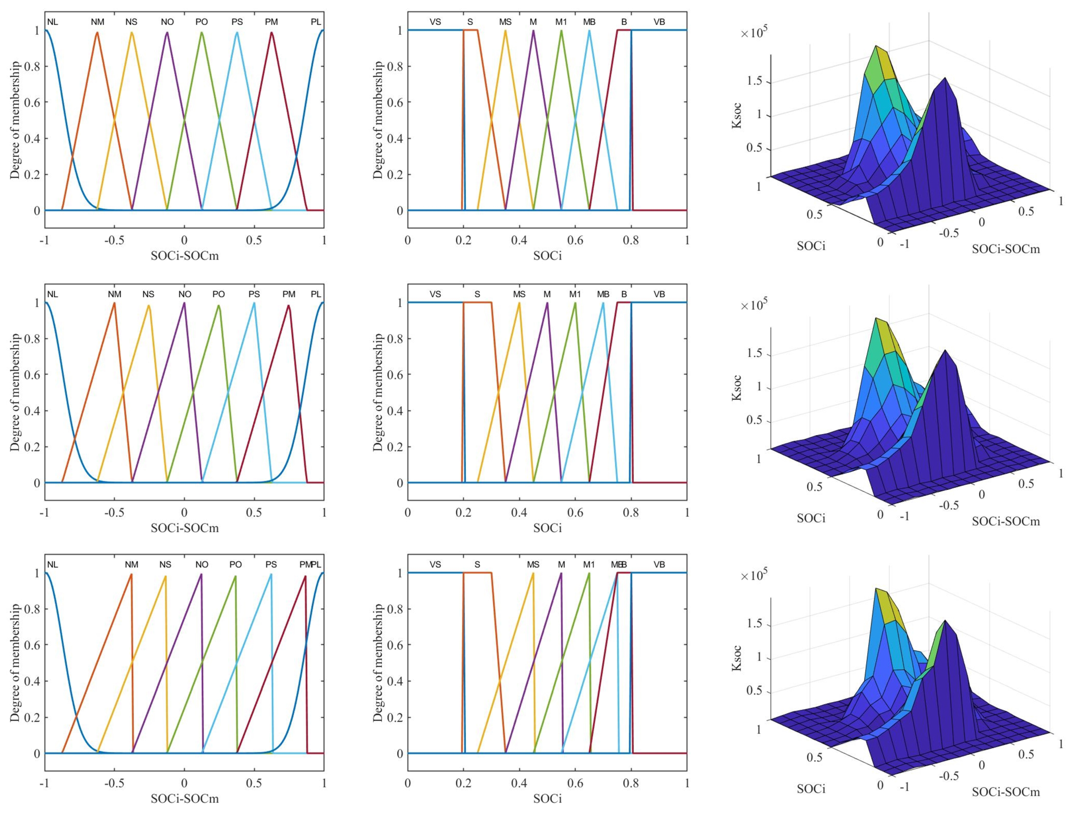
Figure 3 shows multi-fuzzy controllers in the secondary distribution of the power, which include three fuzzy controllers with three dual input single outputs. Due to SOC deviations, it is necessary to design a fuzzy control system for the hybrid energy storage system. The inputs for the fuzzy controller are S O C i and S O C i S O C m , where the basic domain of S O C i is [ 0 , 1 ] , The fuzzy control set is V S , S , M S , M , M 1 , M B , B , V B , representing Very Small, Small, Moderately Small, Medium, Medium 1, Moderately Big, Big, Very Big; The deviation range of S O C i S O C m is [ 45 , 45 ] , and after multiplying by a certain scaling factor, the basic domain becomes [ 1 , 1 ] ; The fuzzy set is N L , N M , N S , N O , P O , P S , P M , P L , representing Negative Large, Negative Medium, Negative Small, Negative Zero, Positive Zero, Positive Small, Positive Medium, Positive Large. The output includes power correction coefficients K s o c . B a t and K s o c . S C . When the deviation S O C i S O C m is very small, the correction coefficient needs to be sufficiently large to be effective. Therefore, after multiplying by a scaling factor, the basic domain is [ 2 e 3 , 2 e 5 ] , and the fuzzy set is { V S , S , M S , M , M 1 , M B , B , V B } . Each controller follows the same set of fuzzy control rules, as shown in Table 1.
To illustrate, Figure 5 shows the three-dimensional surface plots of the input membership functions and the relationships between inputs and outputs for the three fuzzy controllers, using the multi-fuzzy control optimization of batteries as an example.
In the design of multi-fuzzy controllers, appropriate fuzzy controllers are selected for each interval based on the S O C i S O C m deviation, achieving dynamic partition control of the SOC for the hybrid energy storage system. When the slope of the membership function in the fuzzy controller is set higher, the system will make adjustments in response to slight changes in the input variables. When the slope of the membership function in the fuzzy controller is set to be more gradual, the system will adjust in response to a wider range of changes in the input variables.
The initial wind power allocation strategy only considers frequency characteristics and does not take into account the state of charge (SOC) of supercapacitors and batteries, nor the impact of changes in their SOC on power distribution. Considering that the difference S O C i S O C m includes the impact of changes in the state of charge (SOC), a global variable S O C m is introduced. his approach ensures that all energy storage units are treated equally in the control strategy, reducing the influence of a single leader’s SOC and aligning them with the global variable S O C m . Ultimately, this leads to a convergence towards the average SOC of all units. By taking these effects into account, the power of the hybrid energy storage system is adjusted using multi-fuzzy control. Partitioning is conducted based on the S O C i S O C m deviation to adjust the power of the hybrid energy storage system. The specific correction principles are as follows: When the battery and supercapacitor operate within their normal SOC ranges, inaccuracies in the initial power allocation cause deviations between each battery and supercapacitor’s SOC and their average SOC. The deviation range is [ 0 , 45 ] . When the deviation is within the range [ 20 , 45 ] , it indicates a significant SOC difference between them. To quickly align with the average SOC, the rules of Fuzzy Controller 3 are executed. When the deviation is within the range [ 10 , 20 ) , it indicates a smaller SOC difference between them, suggesting that the system has moved out of the SOC danger zone. To follow the average SOC faster, the rules of Fuzzy Controller 2 are executed. When the deviation is in the range [ 0 , 10 ) , it indicates that the SOC deviation between energy storage units is minimal, and the SOC of the storage units is nearly balanced while being out of the danger zone. In this case, the rules of Fuzzy Control 1 are applied. This approach ensures that the energy storage system continuously tracks the average SOC, minimizes the depth of charging/discharging, and reduces unnecessary charging/discharging events. It prevents any single battery from excessive charging or discharging, which could disrupt system stability and reduce the battery’s lifespan. The goal is to prevent state-of-charge (SOC) from exceeding its limits while dynamically adjusting it to keep it within a reasonable range.In Figure 5, P S C and P B a t represent the actual power consumption of the supercapacitor and battery, respectively, while the corrected powers are denoted by P S C and P B a t .
Figure 5. Partition control diagram of battery and supercapacitor SOC deviations from the average SOC
Preprints 121342 g005

4. Example Analysis

4.1. Basic Data

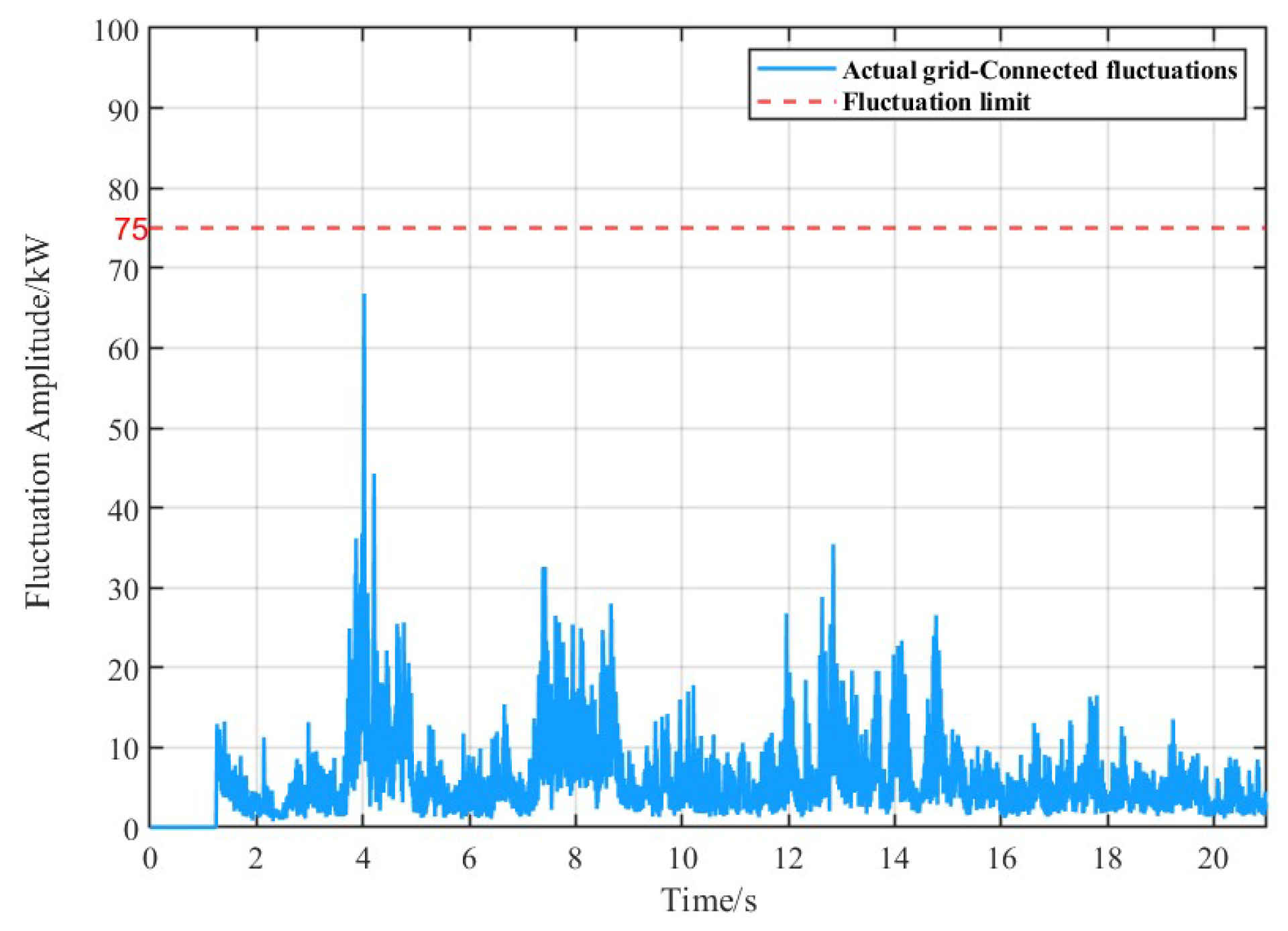
The wind power installed capacity used in this study is 1.5 MW, with a sampling period of 1 minute for the wind power data, resulting in a total of 1,500 data samples. Simulation analysis was conducted in Matlab. The grid connection technical specifications for wind farms selected a wind power fluctuation limit of 75 kW over 10 minutes. During the simulation, wind power data was collected every 0.014 seconds to form the wind power waveform, as shown in the figure. When optimizing the successive variational mode decomposition (SVMD) and variational mode decomposition (VMD) using the SBOA, the number of iterations was set to 20 and the population size to 25. Based on the optimized parameters, [ k , α ] and the maximum α were used to decompose and reconstruct the wind power. The boundary frequency for hybrid energy storage was chosen as Hz. Modes reconstructed above the boundary frequency were used to smooth the power from the supercapacitor, while the modal combination below the boundary frequency selected the lowest fluctuation as the grid-connected power. The remaining wind power reconstruction served as the smoothing power for the lithium battery, as illustrated in the figure. The configuration of hybrid energy storage parameters is shown in the table below:
Table 2. Parameters corresponding to lithium batteries and supercapacitors
Energy Storage Component
Parameter LIB1 LIB2 LIB3 LIB4 SC1 SC2 SC3 SC4
P m a x (kW) 112 120 120 112 100 110 110 110
C R a t e (kWh) 80 85 70 70 40 45 50 40
S O C ( % ) 70.00 21.25 20.50 20.25 68.75 10.27 10.24 10.18
S O C L o w e r ( % ) 20 20 20 20 10 10 10 10
S O C u p p e r ( % ) 80 80 80 80 90 90 90 90
In Table 2, P max ( k W ) denotes the maximum charge and discharge power of the energy storage components. C r a t e ( k W h ) represents the rated capacity. S O C 0 ( % ) indicates the initial state of charge, while S O C L ( % ) and S O C U ( % ) correspond to the lower and upper safety limits of the state of charge, respectively.
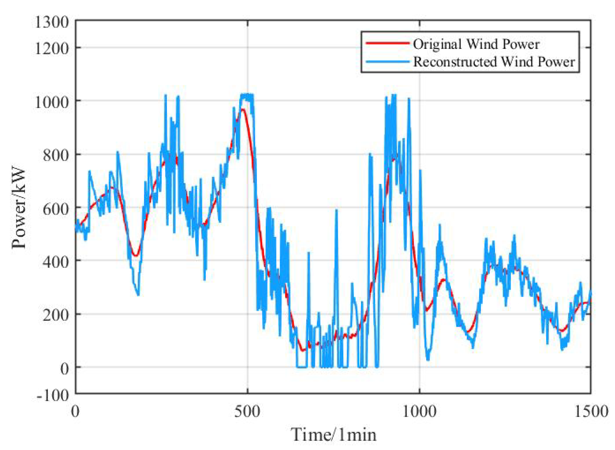
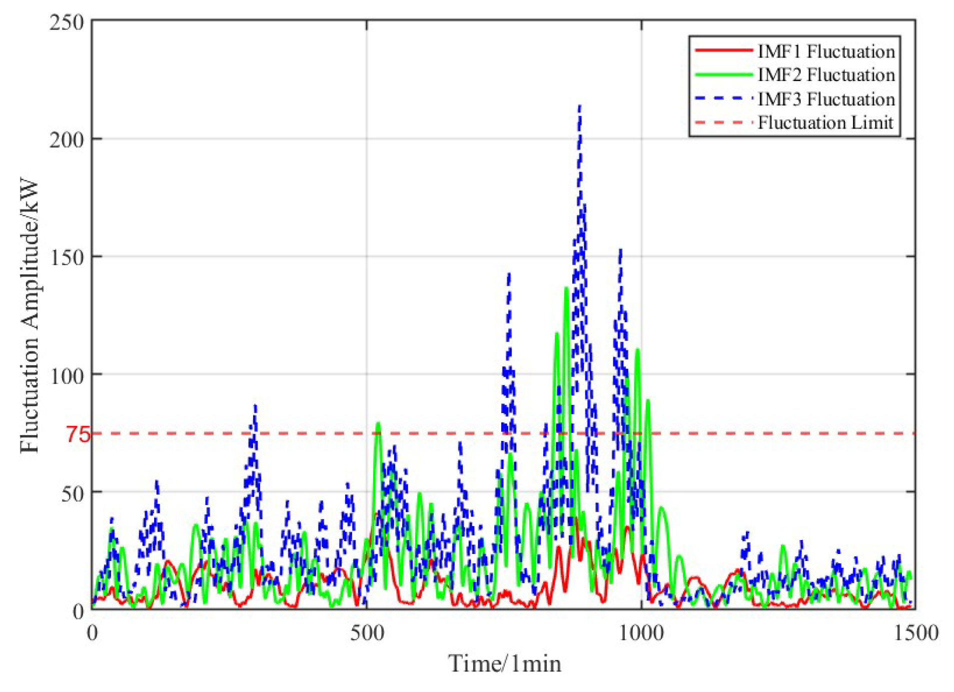
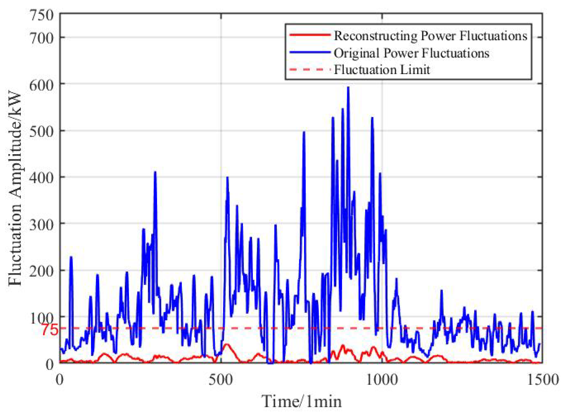
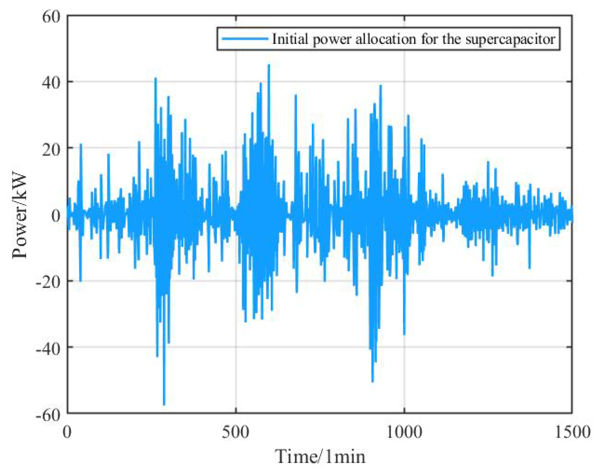
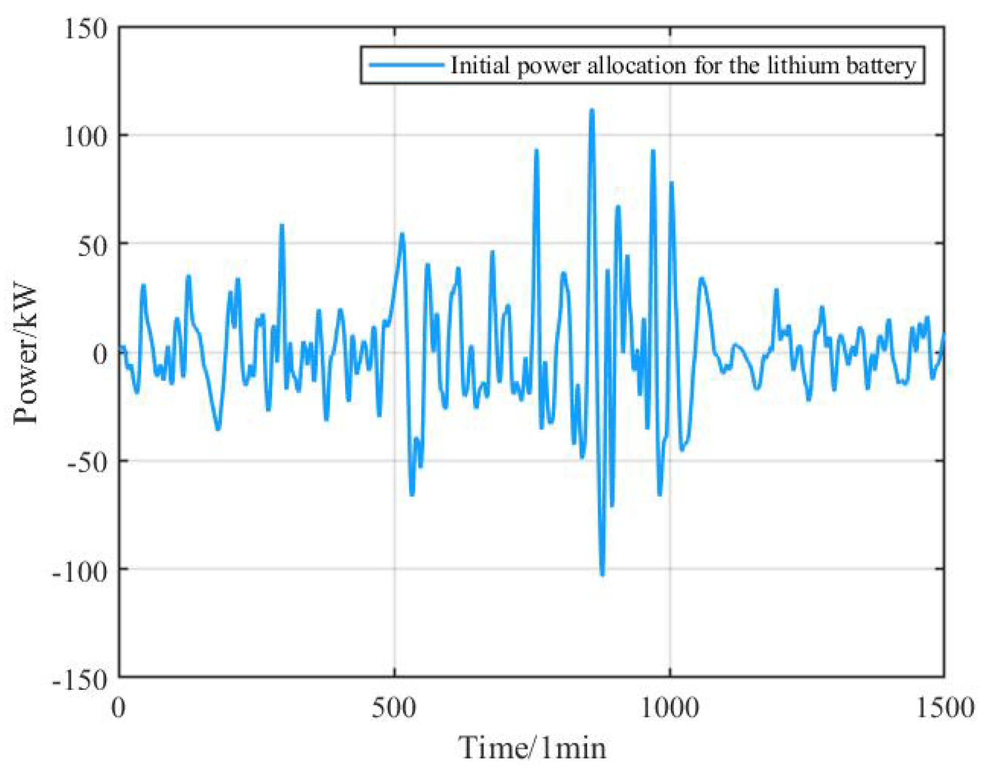
The comparison between the direct grid-connected component and the initial wind power data is shown in Figure 6.; The low-frequency power fluctuations of each VMD decomposed mode are illustrated in Figure 7; The grid-connected fluctuation after smoothing versus before smoothing is depicted in Figure 8; The initial power allocation of the supercapacitor in the hybrid energy storage system is shown in Figure 9, and the initial power allocation of the lithium battery is shown in Figure 10.
After the initial allocation, it can be observed that the application of SBOA-VMD for processing the original signal effectively smooths wind power fluctuations and enhances grid-connected performance. Secondly, the battery energy storage system primarily handles the relatively stable low-frequency power components, while the supercapacitor is responsible for the high-frequency power components that involve frequent charging and discharging with larger instantaneous amplitudes. This allocation aligns well with the characteristics of each component in the hybrid energy storage system.

4.2. Secondary Power Allocation

Due to the inaccuracies in the initial power allocation and the differences among energy storage units, there is a risk of individual storage units having their SOC exceed acceptable limits and exiting operation, which increases the burden on other storage units. This can ultimately lead to the entire energy storage system ceasing to function. Therefore, while storage units work to smooth the power fluctuations from wind energy, maintaining balanced SOC among storage units is also critically important. The risk of SOC exceeding acceptable limits varies across different ranges of S O C i S O C m for energy storage units. By applying different fuzzy control rules, the lithium battery and supercapacitor can operate within safe limits while also achieving SOC balance.
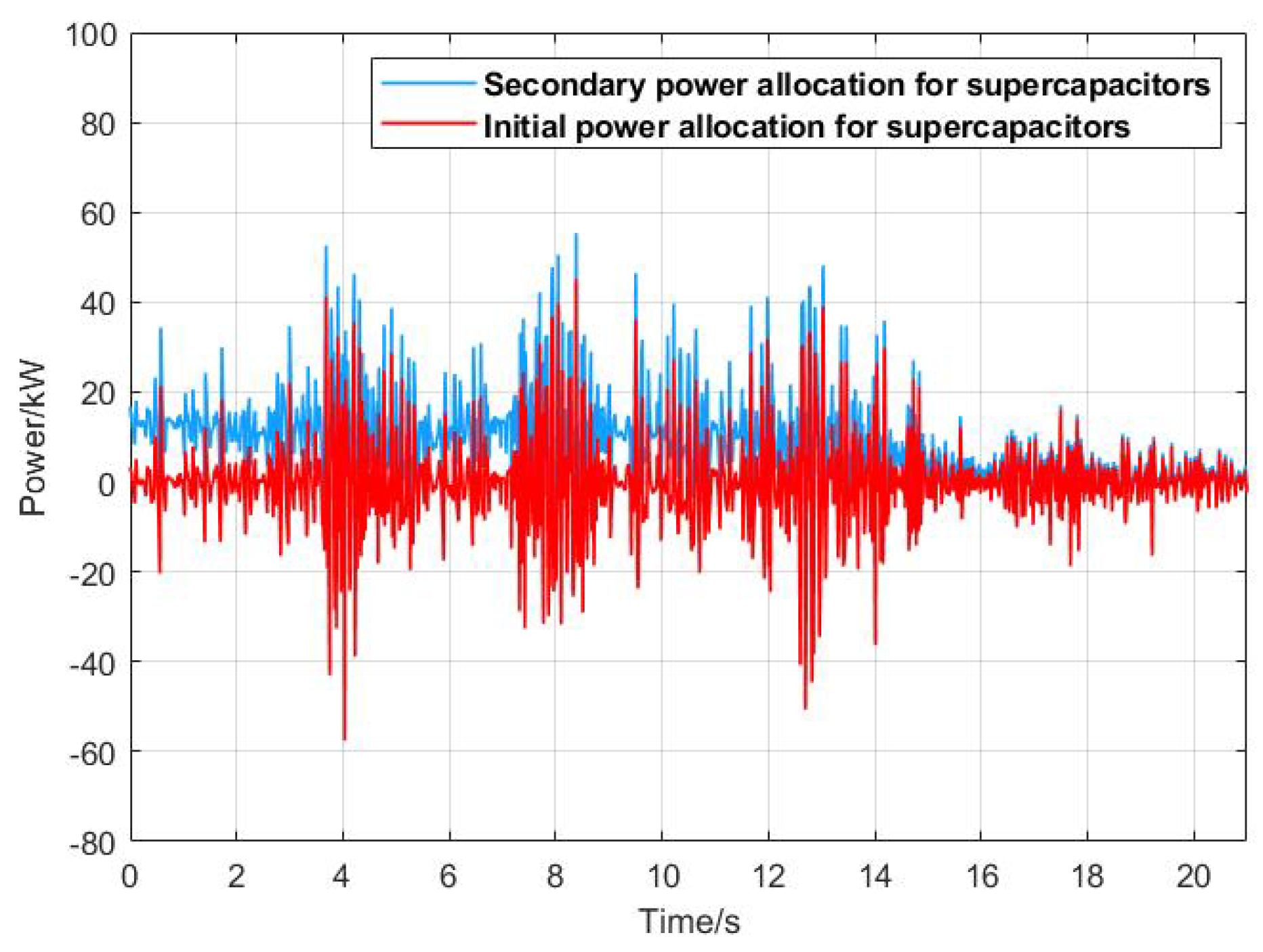
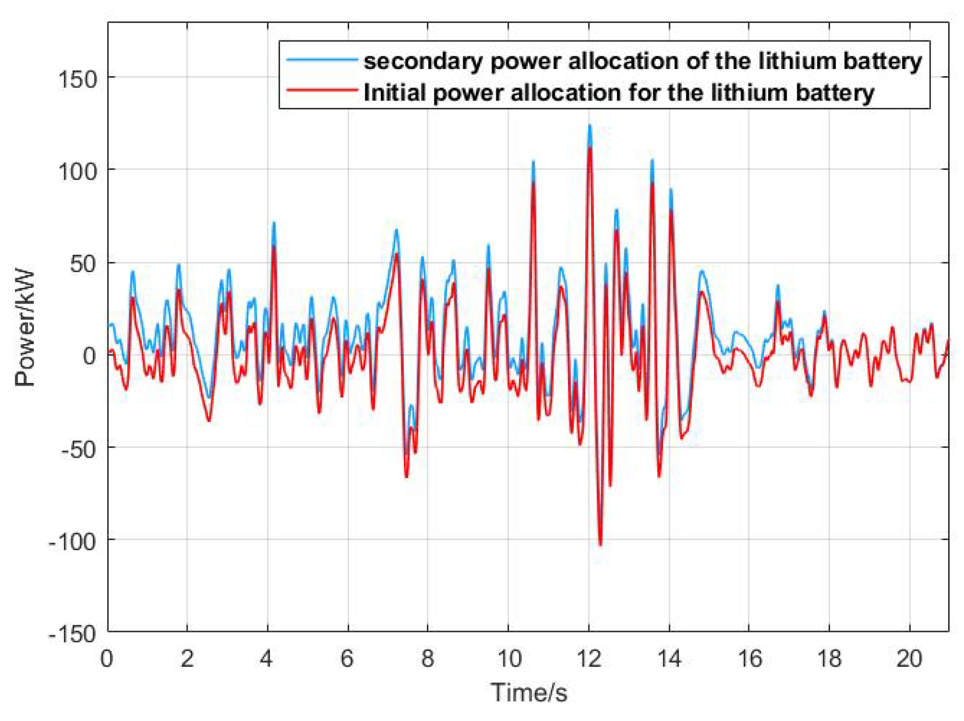
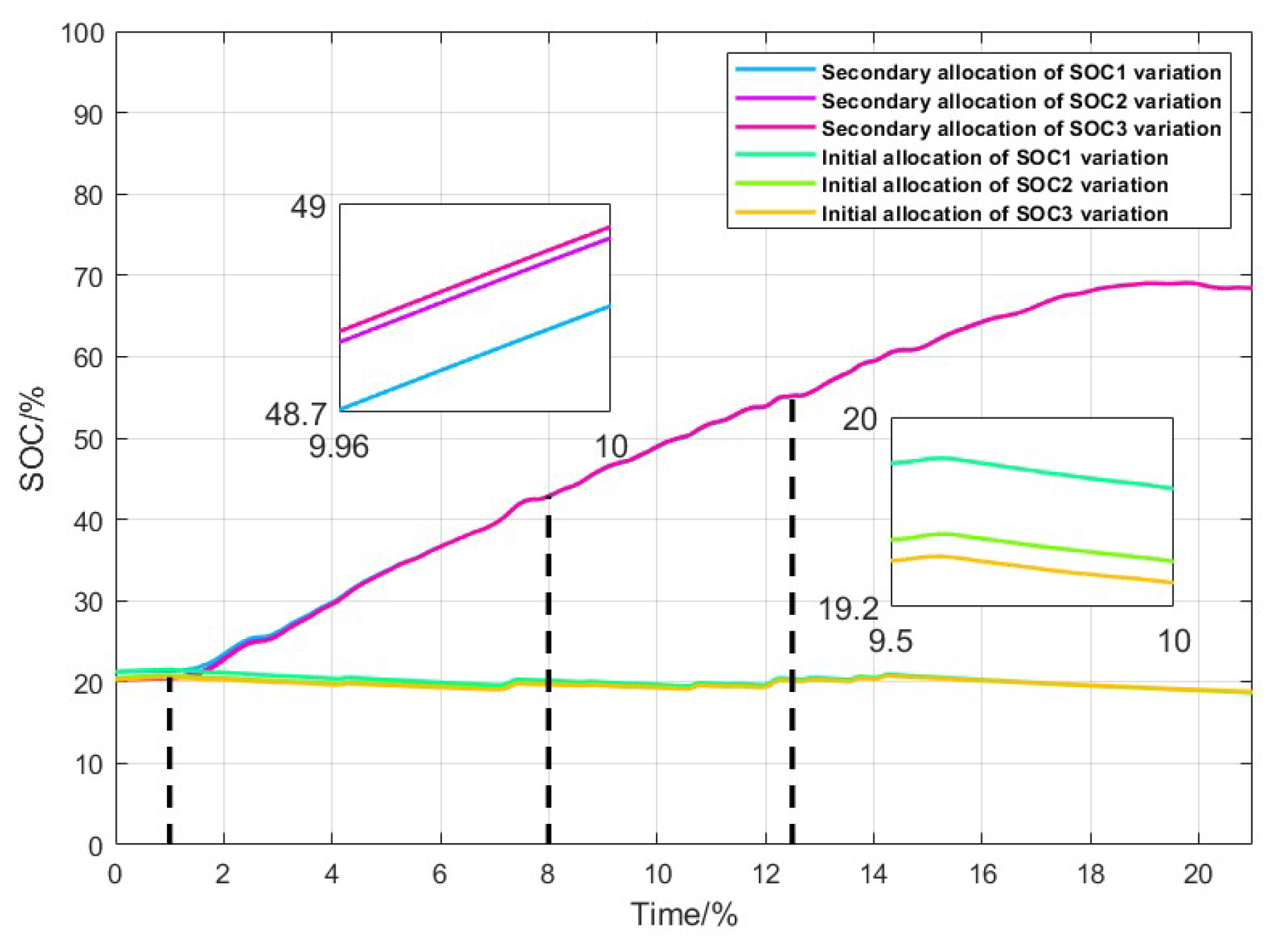
Figure 11 and Figure 12 illustrate the initial and secondary power allocation for supercapacitor groups 2, 3, and 4, as well as battery groups 2, 3, and 4. Figure 13 and 14 show the correction of the SOC of energy storage units after initial and secondary power allocation. Inaccuracies in the initial power allocation can easily lead to group SOC exceeding the specified limits. In Figure 14 and Figure 15, under the control of the multi-fuzzy strategy, the SOC of the energy storage system is in the most critical operating range during the time intervals [1, 6] and [1, 8]. During these periods, a significant adjustment of the hybrid energy storage system’s power is required, and the rules of fuzzy control 3 are implemented to quickly bring the system into the optimal operating range. Subsequently, during the time intervals [6, 8.8] and [8, 12.5], the SOC of the energy storage system has moved away from the danger zone. However, since the SOC has not yet reached equilibrium, power adjustments to the hybrid energy storage system are reduced, and the rules of fuzzy control 2 are applied. During the time intervals [8.8, 21] and [12.5, 21], the SOC of the energy storage units gradually approaches equilibrium. The power adjustment is further reduced, eventually bringing the SOC of the storage units closer to the global average SOC, thereby achieving SOC balance.
Figure 11. Comparison of initial and secondary power allocation for supercapacitor.
Preprints 121342 g011
Figure 12. Comparison of initial and secondary power allocation for lithium battery.
Preprints 121342 g012
Figure 13. Comparison of SOC under initial power allocation and SOC under secondary power allocation for supercapacitors.
Preprints 121342 g013
Figure 14. Comparison of SOC under initial power allocation and SOC under secondary power allocation for lithium batteries.
Preprints 121342 g014
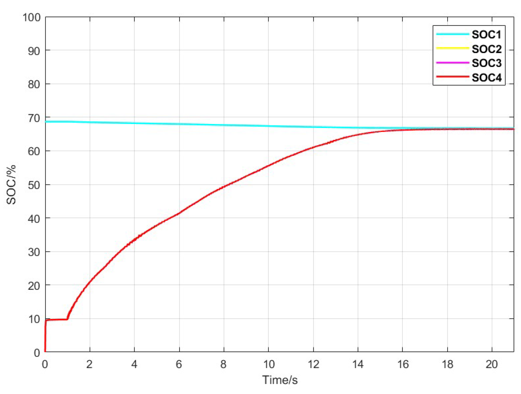
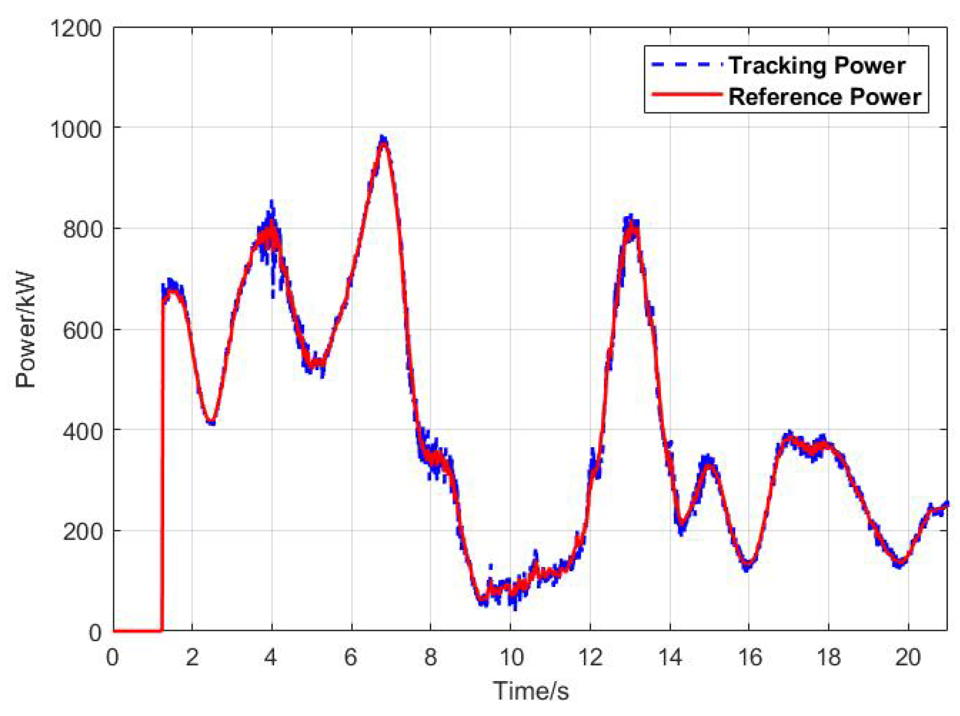
Figure 15 and Figure 16 show the SOC balancing control curves for the supercapacitors and batteries. Figure 17 compares the reference power for grid connection with the actual tracking power. Figure 18 indicates that the fluctuation in tracking power is below 75 kW, meeting the grid connection power requirements.
Secondary power allocation effectively corrects the issue of SOC exceeding limits in hybrid energy storage, ensuring stable operation within a safe SOC range. Additionally, it significantly reduces power fluctuations in the grid-connected wind power hybrid energy storage system, enhancing equipment lifespan and power quality.
Figure 15. Balance curves of SOC for four groups of supercapacitors.
Preprints 121342 g015
Figure 16. Balance curves of SOC for four groups of lithium batteries.
Preprints 121342 g016
Figure 17. Comparison of wind power grid reference power and actual grid power.
Preprints 121342 g017
Figure 18. Actual grid power fluctuation amplitude.
Preprints 121342 g018

5. Conclusion

This study considers the impact of the randomness, volatility, and intermittency of wind power on the characteristics of hybrid energy storage systems and the quality of grid-connected electricity. A power allocation strategy for wind energy hybrid storage systems based on successive variational mode decomposition and multi-fuzzy control is proposed. Through case analysis, this strategy not only effectively smooths the wind power output but also ensures that the state of charge (SOC) of the hybrid energy storage system remains balanced and operates safely and reliably. The conclusions are as follows:
  • By utilizing the variational mode decomposition (VMD) optimized with the Secretary Bird Algorithm and the successive variational mode decomposition (SVMD), the strategy not only achieves the power requirements for grid connection but also maximizes the unique characteristics of each energy storage unit. This approach effectively smooths wind power output and, consequently, extends the lifespan of the energy storage units.
  • This study comprehensively considers the output characteristics of the hybrid energy storage system. By employing "neighborhood communication" among the intelligent agents to obtain a global average as a reference value, and utilizing a dynamic partitioning rule based on the deviation along with the current state of charge (SOC) of the storage units, a multi-fuzzy control strategy is applied. This corrects the tendency of the hybrid storage system to experience overcharging and deep discharging. During this process, power regulation is achieved between the batteries and supercapacitors, ensuring that the adjusted SOC of the hybrid storage system remains within a reasonable range. Ultimately, all storage units converge towards the average SOC value of each unit.

Author Contributions

Conceptualization, R.H. and Jq.L.; methodology, R.H. and Jq.L.; software, R.H. and Jq.L.; validation, R.H., J.Z., Jq.L., Jh.L. and W.C.; formal analysis, Jq.L., Jh.L. and W.C.; investigation, R.H. and J.Z.; resources, R.H. and J.Z.; writing—original draft preparation, R.H., Jq.L.; writing—review and editing, R.H., J.Z. and Jq.L.; visualization, Jq.L., Jh.L. and W.C.; supervision, R.H. and J.Z.; project administration, R.H.; funding acquisition, R.H. and J.Z.. All authors have read and agreed to the published version of the manuscript.
Funding

This research was funded by Natural Science Foundation of Shandong Province, China, grant number ZR2022ME182.

Institutional Review Board Statement

Not applicable.

Informed Consent Statement

Not applicable.

Data Availability Statement

The data is unavailable due to privacy security.

Conflicts of Interest

The authors declare no conflict of interest.

Abbreviations

The following abbreviations are used in this manuscript:
HESS Hybrid Energy Storage Systems
SOC State of Charge
SBOA Secretary Bird Optimization Algorithm
SVMD Successive Variational Mode Decomposition
VMD Variational Mode Decomposition

References

  1. Nouri A; Khodaei H; Darvishan A; Sharifian S; Ghadimi N. RETRACTED: Optimal performance of fuel cell-CHP-battery based micro-grid under real-time energy management: An epsilon constraint method and fuzzy satisfying approach. Energy 2018, 159, 121–133. [Google Scholar] [CrossRef]
  2. Wang X; Zhou J; Qin B; Guo L. Coordinated control of wind turbine and hybrid energy storage system based on multi-agent deep reinforcement learning for wind power smoothing. Journal of Energy Storageh 2023, 57, 106297. [Google Scholar] [CrossRef]
  3. Jung C; Schindler D. A global wind farm potential index to increase energy yields and accessibility. Energy 2021, 231, 120923. [Google Scholar] [CrossRef]
  4. Lin L; Jia Y; Ma M; Jin X; Zhu L; Luo H. Long-term stable operation control method of dual-battery energy storage system for smoothing wind power fluctuations. Energy 2021, 129, 106878. [Google Scholar]
  5. Wan C; Qian W; Zhao C; Song Y; Yang G. Probabilistic Forecasting Based Sizing and Control of Hybrid Energy Storage for Wind Power Smoothing. IEEE Transactions on Sustainable Energy 2021, 12, 1841–1852. [Google Scholar] [CrossRef]
  6. Xiong. L; Liu. X, Zhao. C; Zhuo. F. A Fast and Robust Real-Time Detection Algorithm of Decaying DC Transient and Harmonic Components in Three-Phase Systems. IEEE Transactions on Power Electronics 2020, 35, 3332–3336. [Google Scholar] [CrossRef]
  7. Dai X; Zhang K; Geng J; Liu Q; Wang Y; Kun YU; Qiao Y; Liu Y. Study on variability smoothing benefits of wind farm cluster. Turkish Journal of Electrical Engineering and Computer Sciences 2018, 26, 1894–1908. [Google Scholar] [CrossRef]
  8. Akram U; Khalid M. A Coordinated Frequency Regulation Framework Based on Hybrid Battery-Ultracapacitor Energy Storage Technologies. IEEE Access 2018, 6, 7310–7320. [Google Scholar] [CrossRef]
  9. Masih-Tehrani M; Yazdi MR; Esfahanian V; Dahmardeh M; Nehzati H. Wavelet-based power management for hybrid energy storage system. Journal of Modern Power Systems and Clean Energy 2019, 7, 779–790. [Google Scholar] [CrossRef]
  10. Garcia-Torres. F; Bordons. C; Tobajas. J; Real-Calvo. R; Santiago. I; Grieu. S. Stochastic Optimization of Microgrids With Hybrid Energy Storage Systems for Grid Flexibility Services Considering Energy Forecast Uncertainties. IEEE Transactions on Power Systems 2021, 36, 5537–5547. [Google Scholar] [CrossRef]
  11. Muzaffar A; Ahamed MB; Deshmukh K; Thirumalai J. A review on recent advances in hybrid supercapacitors: Design, fabrication and applications. Renewable and Sustainable Energy Reviews 2019, 101, 123–145. [Google Scholar] [CrossRef]
  12. Vuddanti S; Salkuti SR. Review of energy management system approaches in microgrids. Energies 2021, 14, 5459. [Google Scholar] [CrossRef]
  13. Espín-Sarzosa D; Palma-Behnke R. Energy management systems for microgrids: Main existing trends in centralized control architectures. Energies 2020, 13, 547. [Google Scholar] [CrossRef]
  14. Tsikalakis AG; Hatziargyriou ND; Centralized control for optimizing microgrids operation. IEEE Power and Energy Society General Meeting 2011, 1–8.
  15. Shirkhani M; Tavoosi J; Danyali S; Sarvenoee AK; Abdali A; Mohammadzadeh A; Zhang C. A review on microgrid decentralized energy/voltage control structures and methods. Energy Reports 2023, 10, 368–380. [Google Scholar] [CrossRef]
  16. Yu D; Zhu H; Han W; Holburn D. Dynamic multi agent-based management and load frequency control of PV/fuel cell/wind turbine/CHP in autonomous microgrid system. Energy 2019, 173, 554–568. [Google Scholar] [CrossRef]
  17. Cao Y; Qahouq JA. Hierarchical SOC balancing controller for battery energy storage system. IEEE Transactions on Industrial Electronics 2020, 68, 9386–9397. [Google Scholar]
  18. Mitra SK; Karanki SB. An SOC based adaptive energy management system for hybrid energy storage system integration to DC grid. IEEE Transactions on Industry Applications 2022, 59, 1152–1161. [Google Scholar]
  19. Gao X; Fu L; Zhang Y; Ji F. SOC balance-based decentralized control strategy for hybrid energy storage in integrated power systems. Journal of Power Electronics 2022, 22, 2081–2091. [Google Scholar] [CrossRef]
  20. Cao J; Du W; Wang H; McCulloch M. Optimal sizing and control strategies for hybrid storage system as limited by grid frequency deviations. IEEE Transactions on Power Systems 2018, 33, 5486–5495. [Google Scholar] [CrossRef]
  21. Malik SM; Sun Y; Hu J. An adaptive virtual capacitive droop for hybrid energy storage system in DC microgrid. Journal of Energy Storage 2023, 70, 107809. [Google Scholar] [CrossRef]
  22. Lin L; Cao Y; Kong X; Lin Y; Jia Y; Zhang Z. Hybrid energy storage system control and capacity allocation considering battery state of charge self-recovery and capacity attenuation in wind farm. Journal of Energy Storage 2024, 75, 109693. [Google Scholar] [CrossRef]
  23. Dragomiretskiy K; Zosso D. Variational mode decomposition. IEEE transactions on signal processing 2013, 62, 531–544. [Google Scholar]
  24. Xiao G; Xu F; Tong L; Xu H; Zhu P. A hybrid energy storage system based on self-adaptive variational mode decomposition to smooth photovoltaic power fluctuation. Journal of energy Storage 2022, 55, 105509. [Google Scholar] [CrossRef]
  25. Li Y; Ding Z; Yu Y; Liu Y. Hybrid energy storage power allocation strategy based on parameter-optimized VMD algorithm for marine micro gas turbine power system. Journal of Energy Storage 2023, 73, 109189. [Google Scholar] [CrossRef]
  26. Nazari M; Sakhaei SM. Successive variational mode decomposition. Signal Processing 2020, 174, 107610. [Google Scholar] [CrossRef]
  27. Chen C; Tang W; Xia Y; Chen C. Hybrid-Energy Storage Optimization Based on Successive Variational Mode Decomposition and Wind Power Frequency Modulation Power Fluctuation. Energies 2024, 17, 4391. [Google Scholar] [CrossRef]
  28. Plakhtii O; Nerubatskyi V; Mashura A; Hordiienko D. The Analysis of Mathematical Models of Charge-Discharge Characteristics in Lithium-Ion Batteries. IEEE 40th International Conference on Electronics and Nanotechnology (ELNANO).
Figure 1. Topology of the wind power hybrid energy storage system.
Preprints 121342 g001
Figure 3. Secondary power allocation strategy based on multi-fuzzy control.
Preprints 121342 g003
Figure 4. 3D plots of input membership functions corresponding to fuzzy controls 1 to 3.
Preprints 121342 g004
Figure 6. Comparison of original wind power grid integration with VMD reconstructed wind power grid integration
Preprints 121342 g006
Figure 7. Low-frequency wind power fluctuation amplitude based on VMD decomposition.
Preprints 121342 g007
Figure 8. Comparison of fluctuations between original wind power and VMD reconstructed grid-connected wind power.
Preprints 121342 g008
Figure 9. Initial power allocation results for supercapacitor.
Preprints 121342 g009
Figure 10. Initial power allocation results for lithium battery.
Preprints 121342 g010
Table 1. Fuzzy control rule table
SO C i SO C m
SOC i NL NM NS NO PO PS PM PL
VS VS VS VS VS VS VS VS VS
S MS M M1 VB VB VS VS VS
MS S S M MB MB M1 VS VS
M VS VS VS MS MS VS VS VS
M1 VS VS VS MS MS VS VS VS
MB VS VS M MB B M MS S
B VS VS VS VB VB M1 M MS
VB VS VS VS VS VS VS VS VS
Disclaimer/Publisher’s Note: The statements, opinions and data contained in all publications are solely those of the individual author(s) and contributor(s) and not of MDPI and/or the editor(s). MDPI and/or the editor(s) disclaim responsibility for any injury to people or property resulting from any ideas, methods, instructions or products referred to in the content.
Copyright: This open access article is published under a Creative Commons CC BY 4.0 license, which permit the free download, distribution, and reuse, provided that the author and preprint are cited in any reuse.
Alerts
Prerpints.org logo

Preprints.org is a free preprint server supported by MDPI in Basel, Switzerland.

Subscribe

© 2025 MDPI (Basel, Switzerland) unless otherwise stated