
Submitted:
15 October 2024
Posted:
16 October 2024
You are already at the latest version
Abstract
According to statistics, the leading cause of death among young people is road car accidents. Moreover, one of the factors for road crashes is low-quality road infrastructure. Road signals are part of the road infrastructure, and they are required for safe driving. Furthermore, road signals are essential for an autonomous mobile machine vision to function properly. Hence, road signals should be clear and transparent in all transportation lanes. Unfortunately, road lane markings – one of the most important signals – fade and deteriorate over time because of the paint quality, weather, and exposure to any external object. Moreover, maintaining those markings manually is considered difficult and tedious by some. Literature review shows few autonomous solutions for such a problem. However, none of the solutions is robust for all kinds of markings. In particular, the literature review shows that the present autonomous solutions require human interference to guide the robot in a specified path to paint a new line where usually the robot will localize itself using GPS. This project targets road markings maintenance with a novel idea to use machine vision for inspecting the line state while moving along the line, and if needed, the robot will repaint the road line. The robot was designed following this idea, and the design can be divided into the following: Driving unit, Paint unit, Vision unit, Control unit, Power unit, UI unit. First, the driving unit is made using a three-wheeled differential drive system, where two wheels are motorized wheels, and the third is a freewheel. Moreover, the painting unit contains an air compressor, an HVLP paint sprayer, a pulley system, and a servo motor. At the same time, the robot vision unit consists of a camera, two IR sensors, and two ultrasonic sensors. Also, the control unit is made of a Raspberry Pi, Arduino, and Motor controllers. Furthermore, the power unit has a 12V lead-acid battery, 48V Li-po battery, four 1.5 batteries, and a power bank. Finally, the UI unit includes a cooling fan and a 10” screen. The software is made of a machine vision code using the OpenCV library in Python language. This code is implemented on the RPI to image process the feed from the camera and then communicate with Arduino using the Serial library. Moreover, Arduino code uses C++ language to decode the message from the RPI and control a relay and a servo for the painting unit and motor controllers for the driving unit. After the design and parts acquisition, the whole system was assembled at home using several manufacturing techniques such as drilling, threading, filing, soldering, 3D printing, adhesion, and zipping. Then, each subsystem was calibrated individually. Finally, the testing phase started for each system individually and ended by testing the system as a whole. In the end, the project progress was hindered by several failed tests. However, it was completed within the timeframe with achieving the main performance measures of the mechanical design/assembly, localization/path planning, road line inspection accuracy, and painting performance.
Keywords:
Robotics
; Design
; Manufacturing
; Line Marking
; Thesis
1. Introduction
Safe transportation is of utmost importance to a developed society. However, cars accidents represent the highest numbers among all types of transportations. According to ASIT (Association for Safe International Road Travel) [26], approximately 1.35 million people die in road crashes each year; on average, 3,700 people lose their lives every day on the roads. An additional 20-50 million suffer non-fatal injuries, often resulting in long-term disabilities. Furthermore, road traffic injuries are the leading cause of death among young people aged 5-29. Young adults aged 15-44 account for more than half of all road deaths. Road crashes may cost countries 2-8% of their gross domestic product. Moreover, ASIT blame road crashes on these factors:
- Poor road infrastructure and management
- Non-road worthy vehicles
- Unenforced or non-existent traffic laws
- Unsafe road user behaviors and
- Inadequate post-crash care.
Hence, one of the requirements for a safe and smooth traffic flow is clear road markings throughout the road to organize the traffic for good road infrastructure. However, the painted markings fade with time due to several factors such as exposure to the sun, water, and dust.
Road markings are essential to traffic safety. They are essential for minimizing accidents and enhancing traffic flow. Furthermore, older drivers have slower reaction times and less vision. Also, at nighttime and during climate phenomena that affect sight, markings and signs could be the only guidance for drivers [21]. Furthermore, the bloom of robotics and machine vision and the promise of a future full of autonomous driving mobiles signify the demand and importance of road markings and signals.
The main issue presented here is that road markings fade with time, and the challenges lie in maintaining their quality with the presence of uncontrollable factors such as weather and controllable factors such as cost, time, and labor.
This report is written as follows: First, a literature survey showcasing the existing papers tackling some challenges such as lane detection and classification and comparing several related products. After that, the problem statement and the suggested solution. Then, the system design. And finally, the results, evaluation, and challenges throughout this journey.
2. Literature Review
2.1. Robotic Perception and Machine Vision
This field is rich in articles and studies. For example, [20]. A robotic solution for road markings contains several challenges—first, robotic perception and machine vision. In [19], a model was tested using machine vision in a road to recognize the lines, and [2] discusses the classification of road lines and how machine vision can extract meaning. Also, [17] addresses extracting information from a road marking and its importance for autonomous vehicles using machine vision. While [11] presents a method to extract road markings using only a Laser Rangefinder sensor.
2.2. Robotic Control
2.3. Robotic Design and Construction
2.4. University Marking Robot Projects
2.5. Marking Robot Products
There are several related products in the field. Currently, the majority of the used product and machines are manually operated. However, there are some autonomous machines for painting road markings, as shown in Table 2. Several companies provided many solutions. For example, TinyMobileRobots® has one autonomous robot for marking new lines in a road [7] and two other autonomous robots for painting soccer field markings [8,10]. The other solutions are not autonomous; however, they offer reliability and precision.

Table 1.
Table of Abbreviations.
| UI | User Interface |
| RPI | Raspberry Pi |
| SSH | Secure Shell Protocol |
| VNC | Virtual Network Computing |
| GUI | Graphical user interface |
| HVLP | High Volume Low Pressure |
| PLA | Plastic Liquefying Agent |
| VESC | Vedder Electronic Speed Controller |
| FPS | Frames per second |
Table 2.
Related products.
| Product | Operation / Specifications | Pros | Cons |
TinyPreMarker [7] 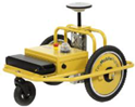
|
The desired marking is drawn on a tablet. Localization using GNSS receiver. Completely autonomous. |
High Marking speed of 7 km/h. The relatively lightweight of 18 kg. Autonomous. |
Small can size of 750ml. No previous line recognition. |
LineLazer V 3900 [21] 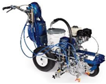
|
Manually controlled precision painting machinery. |
Many use cases. Precision. Easy to adjust and use. |
Manual. Huge size. |
TinyLineMarker Pro [10] 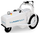
|
Set on a soccer field, autonomously paint the field markings. Weigh 35 kg. |
Autonomous. Reliable: 1-2 cm precision. Battery life for a full day. Paint capacity of 10L. Marking speed of 1m/s. |
Narrow use case ( for soccer fields only ). |
Kontur 600 [16] 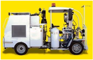
|
A massive machine with a working station to control the machine. Weigh 4300 kg with an engine of 61 hp. |
Three types of paint, reflective glass spray. Huge paint capacity of 600 kg of paint and 170 kg of glass beads. |
Manual. Huge size. |
Shmelok HP Structure [18] 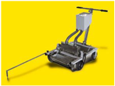
|
Manual trolly with basic operation. Weigh 100 kg. |
Relatively low cost. | Manual. Paint prepared on the spot. Pushed manually. |
TinyPreMarker Sport [8] 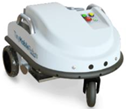
|
Set on a soccer field, autonomously paint the field markings. Weigh 25 kg. |
Lightweight. Easy to operate. Autonomous. Reliable: 1-2 cm precision. Battery life for a full day. |
Smaller capacity compared to [10] with 5L. Slower marking speed compared to [10] (0.7 m/s). |
3. Problem Statement
Road characteristics play a huge role in transportation safety and quality. According to statistics, the leading cause of death among young people is road car accidents. Moreover, one of the factors for road crashes is low-quality road infrastructure and unclear road markings. Unfortunately, road markings fade over time and get deteriorated because of their exposure. Hence, road markings maintenance is of utmost importance.
Furthermore, even though road maintenance is essential, it is insufficient due to uncontrollable factors such as weather and controllable factors such as cost, time, and labor.
Moreover, the existing solutions suggest an autonomous robot to paint new lines; hence, there is no robust solution for maintaining existing lines.
Therefore, we need a robust solution for Road Markings maintenance to improve roads infrastructure and reduce road accidents.
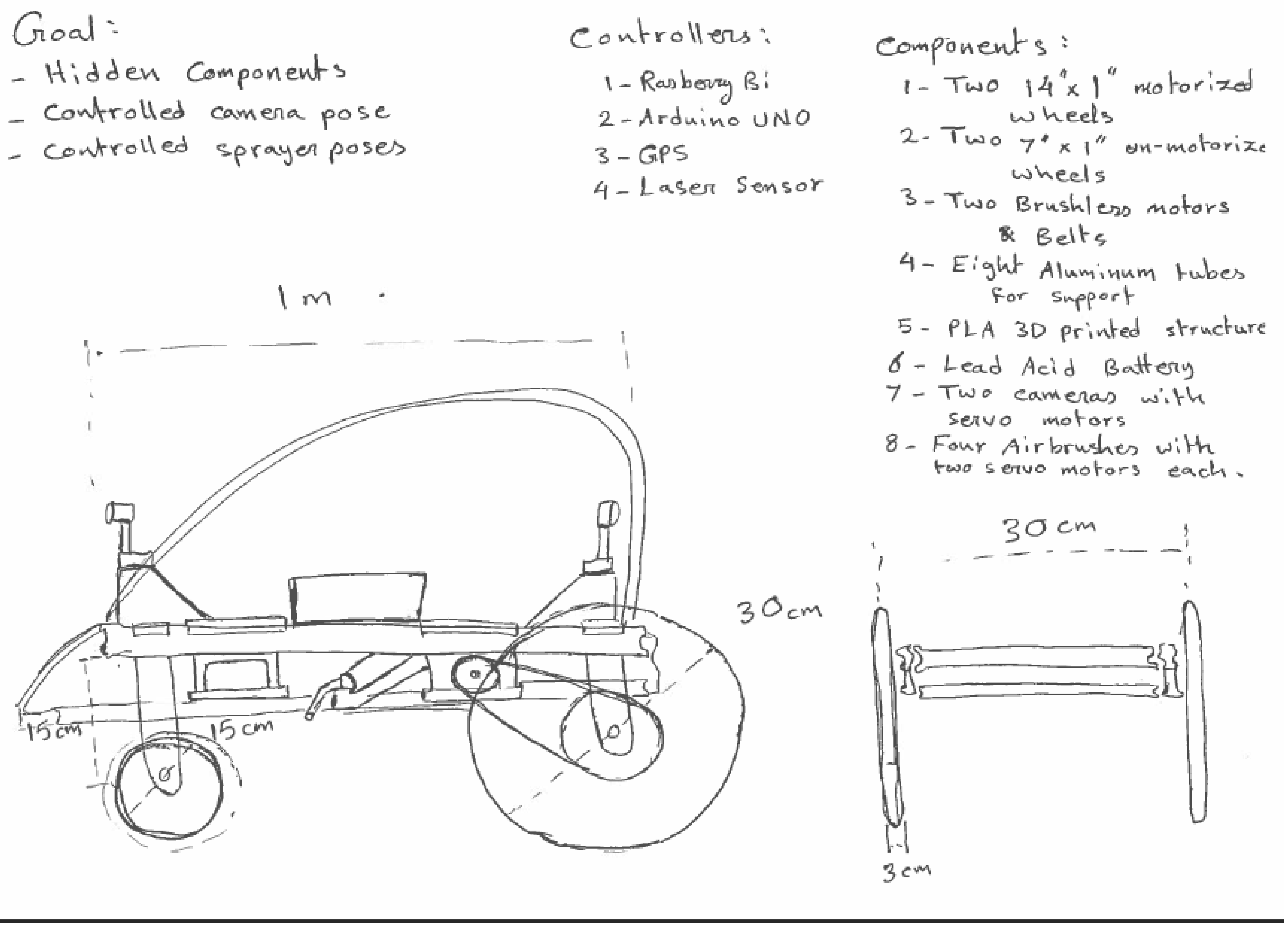
The proposed solution is an autonomous robot that will maintain a road lane by recognizing the road marking using machine vision. The early-stage workflow was as follows. First, deploy the robot using a simple switch to engage the power supply. Then, place the robot on the desired location, and it will detect the line on the asphalt using a camera and image processing. After that, it will follow the line while analyzing its state. Finally, it will paint the affected area to recover the lost color if it has deteriorated beyond a certain threshold.
4. System Design
4.1. Hardware
Bearing in mind the tasks to be performed by the robot, such as motion and image processing, Table 3 and the following Figures shows the robot parts to accomplish those tasks.
Figure 1.
Printed circuit boards (PCBs) used in the robot.
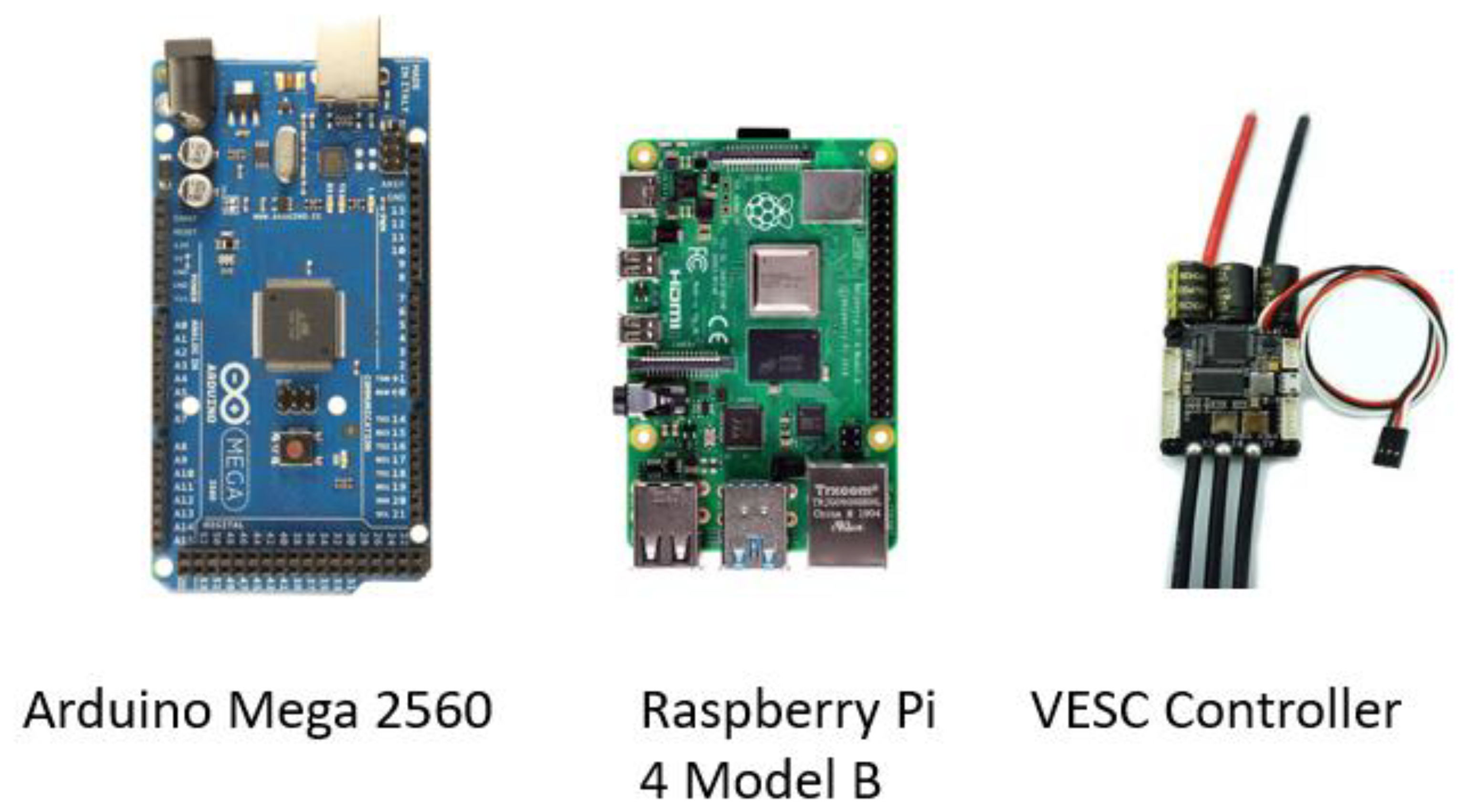
Figure 2.
Sensors.
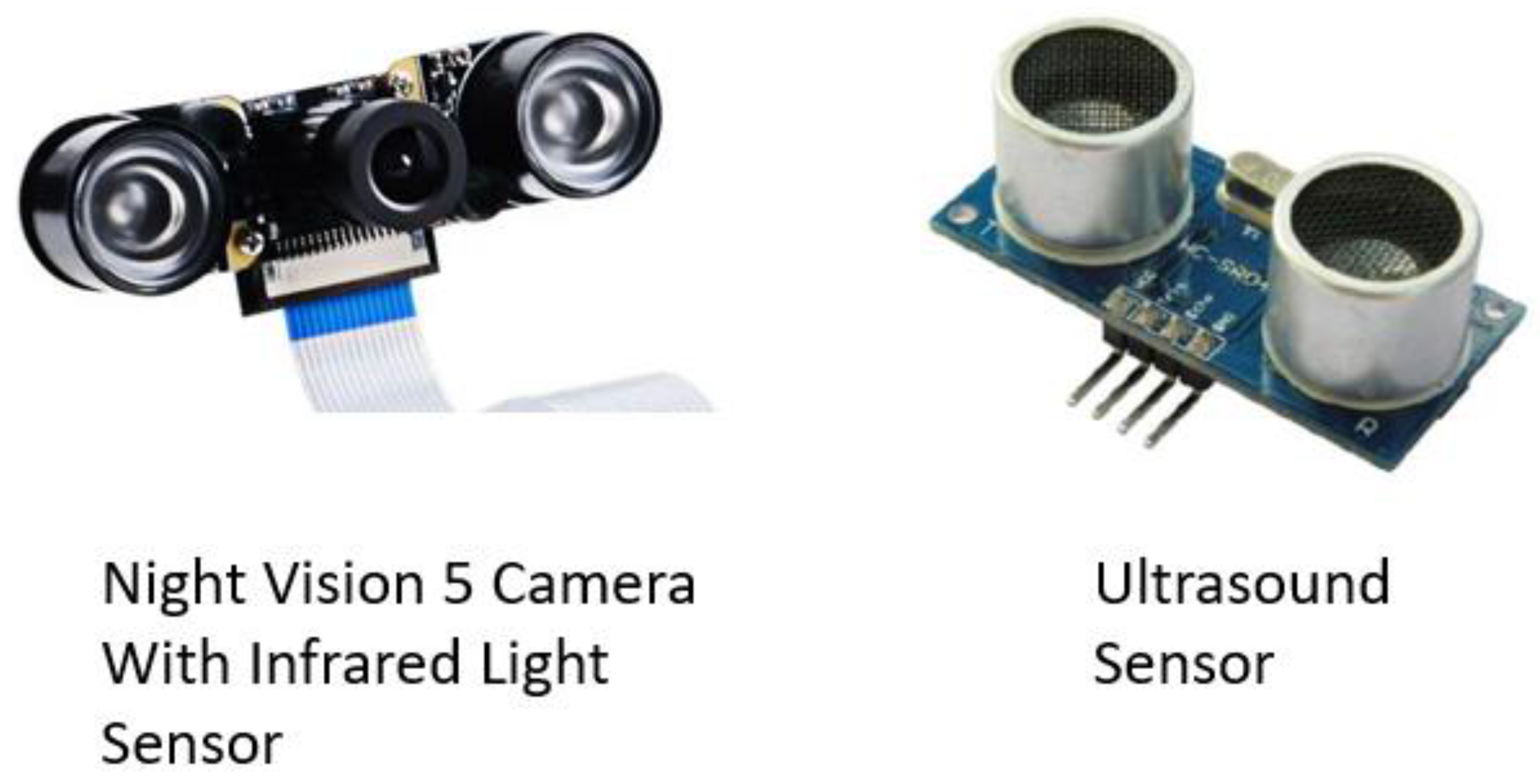
Figure 3.
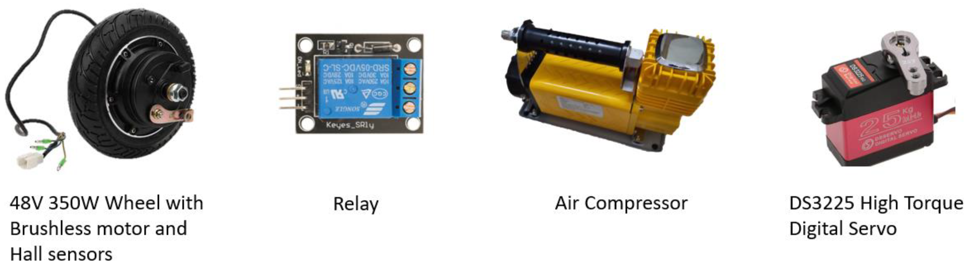
Actuators.
4.1.1. Mechanical System
The mechanical system consists of a chassis of Aluminum extrusions as a frame, cardboards, and 3D printed PLA+ mounts. The characteristics of each material are found in Appendix A. In addition to the chassis, wheels are designed to support the robot directly without a suspension system. Finally, all parts are mounted on the chassis. The final design is shown in Figure 4, Figure 5, Figure 6, Figure 7 and Figure 8.
The following sections will break down the mechanical system into its sub-assemblies.
Chassis
Frame
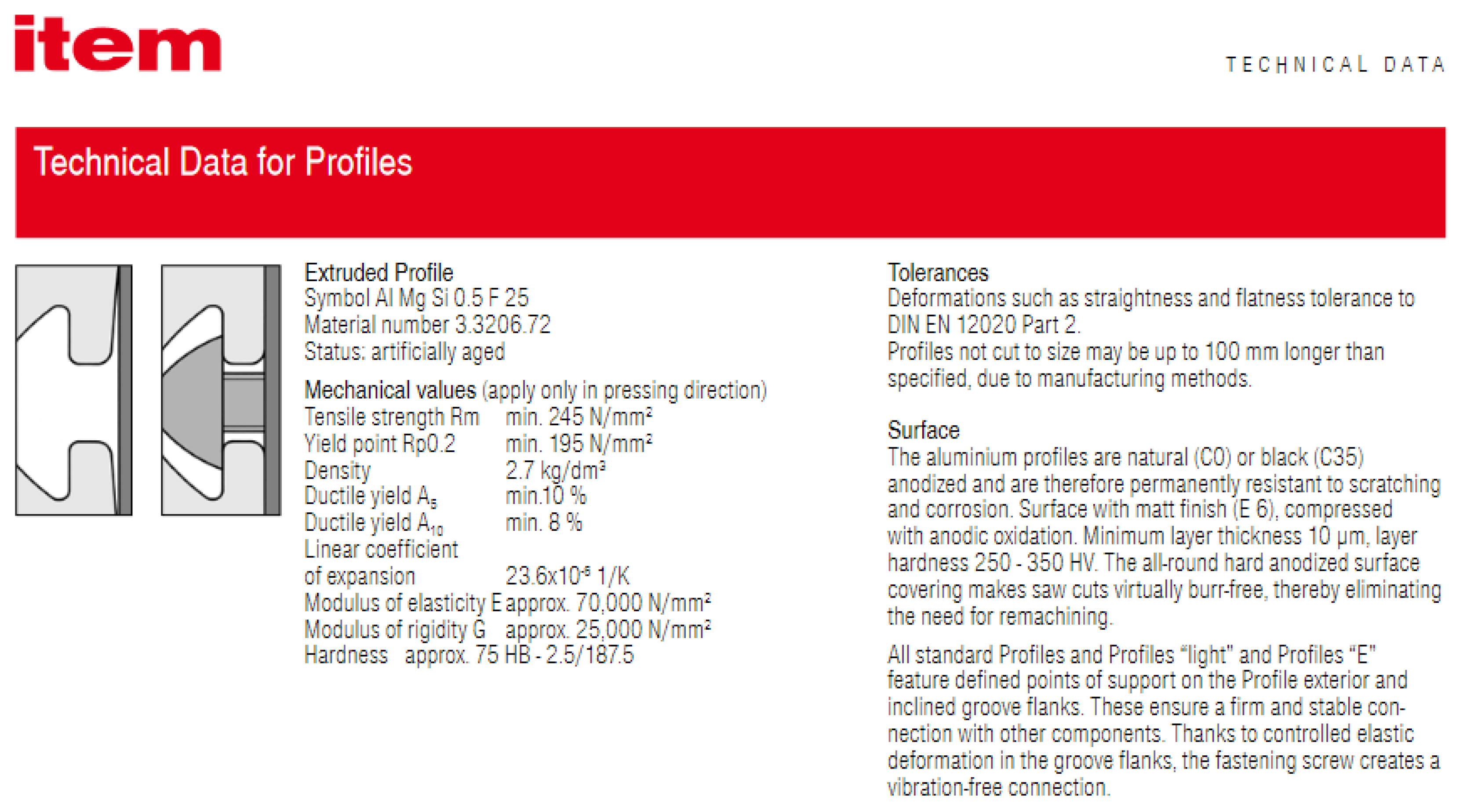
The frame consists of aluminum extrusions, as shown in Figure 9; this design selection was based on Table 4. The aluminum extrusion data sheet is in the Appendix.
The aluminum extrusions were received with nominal dimensions error of ~4mm in cutting length. That made me file them to the appropriate length. In addition, they required drilling and tapping to assemble them using bolts, square nuts, and Allen key. In the end, they were assembled, as shown in Figure 10.
Cover
The robot surface and cover are made of cardboard, selected mainly because of its availability and ease of assembly. The surface was installed first above the frame, then the sides and the top pieces were fixed using zippers, super glue, and a glue gun. Also, all components were fixed on the surface using the same techniques. In the end, they were assembled, as shown in Figure 11.
Painting Unit
The painting mechanism was selected based on Table 5. A further breakdown of the subassembly is in the following sections.
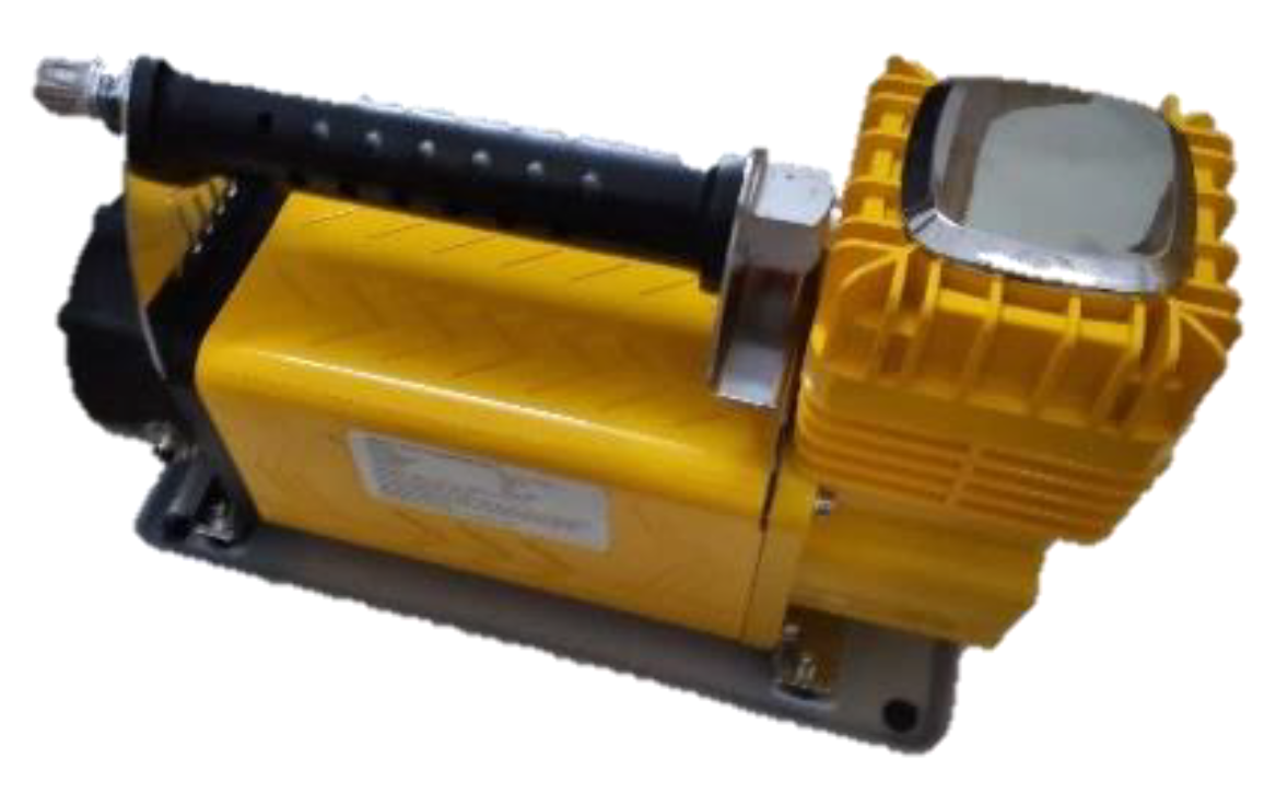
Air Compressor
The air compressor is purchased from the local market with the following specifications:
- Voltage: DC 12V-13.8V
- Amperage: 45A
- Max. Pressure: 150 PSI
- Airflow: 160 L/min
Figure 12.
Air compressor.
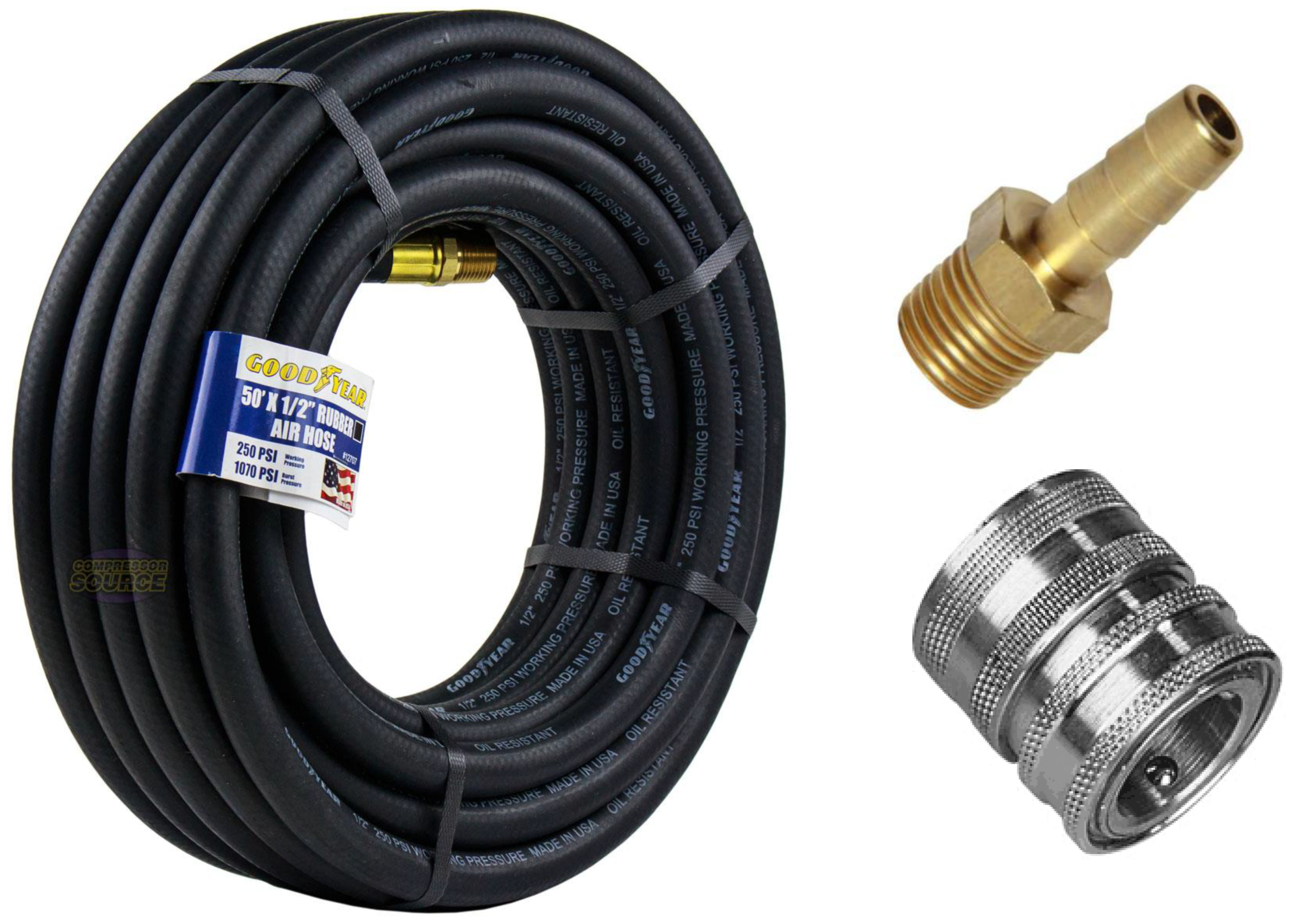
In addition, the parts shown in Figure 13 are assembled to the compressor to make the final system:
Figure 13.
Air hose, Coupler, and hose connector.
Paint Sprayer
The paint sprayer is purchased from the local market and selected based on the air compressor specifications. Hence, the sprayer operational pressure and airflow volume should be meeting the specifications of the air compressor. Nonetheless, the sprayer selection between numerous types was on HVLP sprayers that could operate on lower pressure. Hence, the final design contains a gravity-fed HVLP sprayer with three adjustment knobs for spray pattern control, as shown in Figure 14.
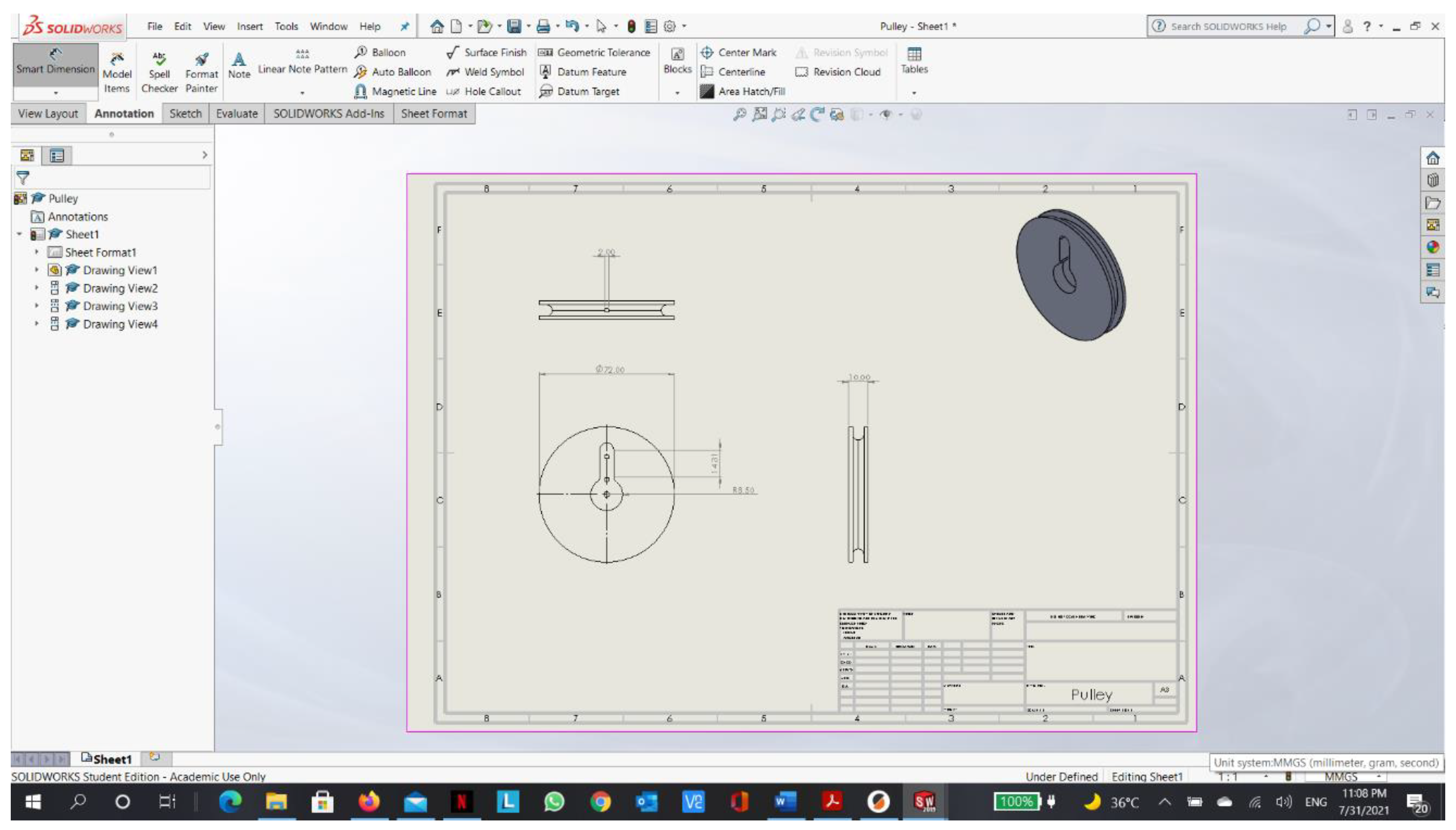
Pulley System
Initially, the design contained a control valve to control the compressed airflow, which will spray the paint if the sprayer trigger was typically closed. However, one of the late tests concluded with a failure of the valve with the valve cracking and exploding. Nonetheless, a new design came for a triggering system. The final design includes a fully designed and printed pulley system to allow a servo motor to pull the sprayer trigger and close it through a string attached to the pulley system, as shown in Figure 15.
In addition, the servo was selected after a thorough comparison between analog and digital servos. It turns out that digital servos have higher resolution than analog servos since the frequency of the PWM signals is ten times higher. Moreover, they have fewer dead-band zones than their analog counterparts.
Finally, they have much higher resistance to external rotation than analog servos. Therefore, the digital servo was selected.
Driving Unit
The driving unit was designed based on Table 6. After that, all the parts were purchased from the local market. Unfortunately, the purchased parts had reliability issues. For one, the hall sensors in the motorized wheels are inaccurate and contain noise. Another reason is that each wheel differs in its current specifications slightly, which makes controlling them with the exact current yield different speeds and torques. Also, the castor wheel is not smooth enough, which hinders the performance of the differential drive. Nonetheless, the components are shown in Figure 16 and Figure 17.
4.1.2. Electrical System
Power
Three primary circuits have been designed. The first is a circuit powered by a 48V Li-po battery for the brushless motors. Whereas the second is powered by a 12V lead-acid battery for the air compressor and cooling fan. Finally, the third is powered by four 1.5V batteries connected in parallel for the servo motor. The electrical circuits are shown in Figure 18.
Signal
Signaling communication connections are designed for all components with the controllers. For example, the connection is shown in Figure 19.
4.2. Software
The software architecture is shown in Figure 20, and further breakdown is detailed in the following sections.
4.2.1. Communication Establishment between RPI and External Computer
In order to control a headless RPI (where RPI is not connected to a display monitor), communication between the control station (external computer) and the RPI should be established. Before starting the procedure of connection, SSH and VNC should be enabled from the RPI through the following steps and as shown in Figure 21:
- Open the “Raspberry Pi Configuration” window from the “Preferences” menu.
- Click on the “Interfaces” tab.
- Select “Enable” next to the SSH row and VNC row.
- Click on the “OK” button for the changes to take effect.
- In order to connect to the Raspberry Pi from another machine using SSH or VNC, we need to know the Pi’s IP address. So, make sure that RPI is connected to the same network as the external computer, then type “hostname -I” will display the IP address in the terminal.
Then, install PuTTY on the external computer. “PuTTY is an SSH and telnet client, developed originally by Simon Tatham for the Windows platform.” [23] to connect to the RPI terminal from an external computer with Windows OS. After that, use the PuTTY program to connect to the IP address of the RPI using the SSH connection type, as shown in Figure 22. Moreover, to have a GUI instead of the terminal, I used a VNC server. “Virtual Network Computing is a graphical desktop sharing system that allows you to remotely control the desktop interface of one computer (running VNC Server) from another computer or mobile device (running VNC Viewer).” [24]. However, for a headless RPI, there is no graphical desktop to display; hence, we need to establish a virtual desktop that exists only in Raspberry Pi’s memory, as shown in Figure 23. In order to do that, type “vncserver” in the terminal, then take the displayed IP address and use it in a VNC viewer application in the external computer to connect.
4.2.2. Communication Establishment between RPI and RPI Camera
The Pi camera module is a portable, lightweight camera that supports the RPI. It communicates using the MIPI camera serial interface protocol. MIPI is the most widely used embedded vision interface. It was designed for mobile devices and is updated by the MIPI Camera Working Group every two years. Some applications include head-mounted VR devices, IoT appliances, and 3D facial recognition security systems.
MIPI has a high bandwidth of 6 Gb/s. It has four image data lanes that are each capable of 1.5 Gb/s. MIPI CSI-2 is faster than USB 3.0. It is an efficient, reliable protocol that can handle video from 1080p to 8K and beyond. Thanks to its low overhead, it has a higher net image bandwidth. CSI-2 also uses fewer resources from the CPU thanks to its multi-core processors. The RPI camera and its pins are sown in Figure 24.
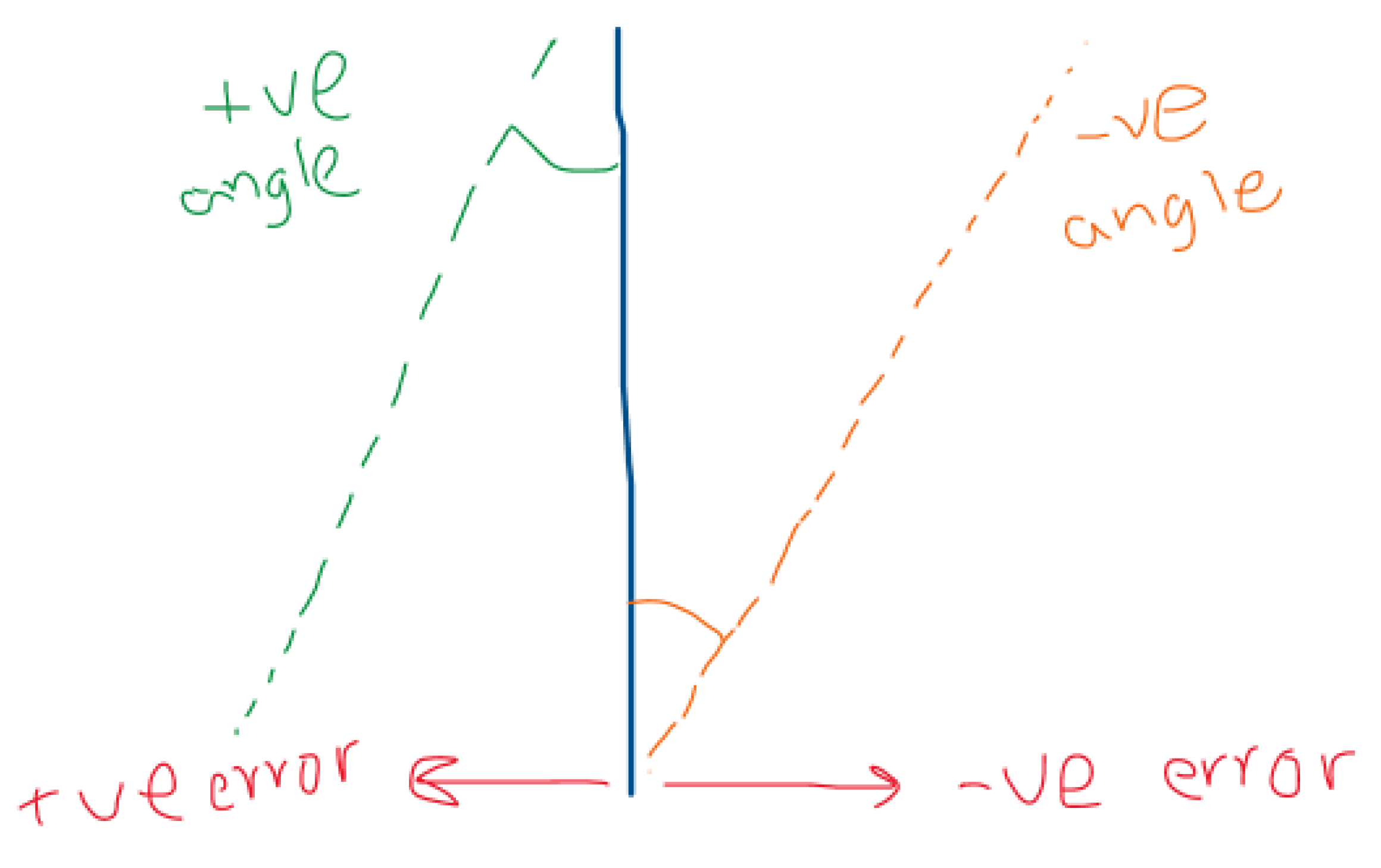
4.2.3. Machine Vision Code for Line Following and Line Degradation State Recognition
We need three crucial outputs from the machine vision in order to actuate the robot:
- Is the robot to the right or left of the line, and how far is it from the line.
- Is the robot moving in parallel to the line or angled towards/from the line?
- Is the line in good condition, or does it need repainting?
Furthermore, we need to do the following image processing techniques beforehand:
- Recognizing the line
- Making a contour to the line
- Warping the line
- Drawing a centerline to the line
After that, we can calculate the error between the centerline of the camera field of vision and the drawn centerline to acquire the first output. Then, using trigonometric function and multiple points from both centerlines, we can acquire the second required output as shown in Figure 26. Finally, we used the contoured line in the image feed and statistical analysis on the pixels trapped inside the contours to find the third required output. The idea used is as follows: each pixel trapped inside the contour should be white (255 in the Grayscale). Furthermore, by finding a low average of the pixels, the output will be “line is degraded and need painting.” Moreover, if the standard deviation was higher than a certain threshold, the output will be “line has cracks and need repainting.”
Figure 25.
Machine Vision for line detection.
4.2.4. Machine Path Planning Code for Line Following Robot
We need the following criteria from the robot movement:
- Stability
- Minimum steering and deviation
- Low speed to control the painting
Furthermore, using the concept illustrated in Figure 27 and kinematics equations, we found the approximate rpm for the motors:
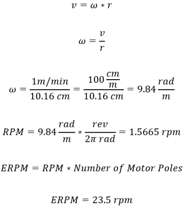
Where
v: linear velocity
ω: angular velocity
RPM: revolutions per minute
ERPM: electrical RPM
Hence, If ERPM was set to be 100 rpm, the robot will cover 4.2558 meters in one minute.
Also, the control method of choice is the control to reference pose, where motion control can be performed by controlling motion from some start pose to some goal pose (reference pose) or by reference trajectory tracking. The path or trajectory to the reference pose is not prescribed in the reference pose, and the robot can drive on any feasible path to arrive at the goal.
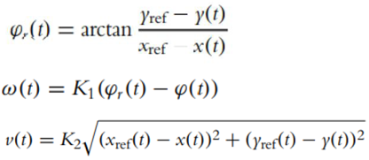
Where
φr reference angle
K1: controller gain (P controller)
Moreover, finally, the logic of the path planning was set as follows: After acquiring the error and angle error from RPI machine vision, we can calculate the angular velocities of the motors using reverse kinematics. Hence, using these equations, the equations are shown in Figure 19. With the addition of linear velocity limitation to be < 10 meters/minute, we can find the angular velocity for each motor. Also, the code is in the Appendix.
4.2.5. Communication Establishment between RPI and Arduino
The RPI is a full-fledged microcontroller capable of running different processing scripts such as machine vision and AI algorithms. However, RPI’s negative side is that it does not present a good I/O (input/output interface between the microcontroller and electronic circuits). On the other hand, Arduino is built for I/O, making the RPI-Arduino interface a powerful tool.
There are several ways for RPI to communicate with Arduino, such as I2C using RPI GPIO or Serial communication. I2C protocol offers higher throughput than the serial protocol. However, there are several issues with the I2C protocol, such as no universal connector and the variant voltage. Serial connection, however, is more simple and safe to use. Moreover, there are ready-to-use libraries in both Arduino IDE and Python in RPI for serial communication. The complete code, along with the communication establishment, is in Appendix F and Appendix G.
After the machine vision algorithm in RPI, the communication between the RPI and Arduino was tested to do the following:
-
Sending a string type of message:
- ○
- Error is X\n
- ○
- Angle Error is Y\n
- ○
- Lane SD is Z\n
- ○
- Where X, Y, Z are arbitrary numbers.
-
The format of the message is as follows:
- ○
- ExAySz\n
-
The Arduino will decode the message as follows:
- ○
- Take substring between E and A and store it in a variable called error
- ○
- Take substring between E and A and store it in a variable called Angle
- ○
- Take substring between E and A and store it in a variable called STD
- Converting those string variables into integer values
- Using the values in Arduino accordingly for the path planning algorithm.
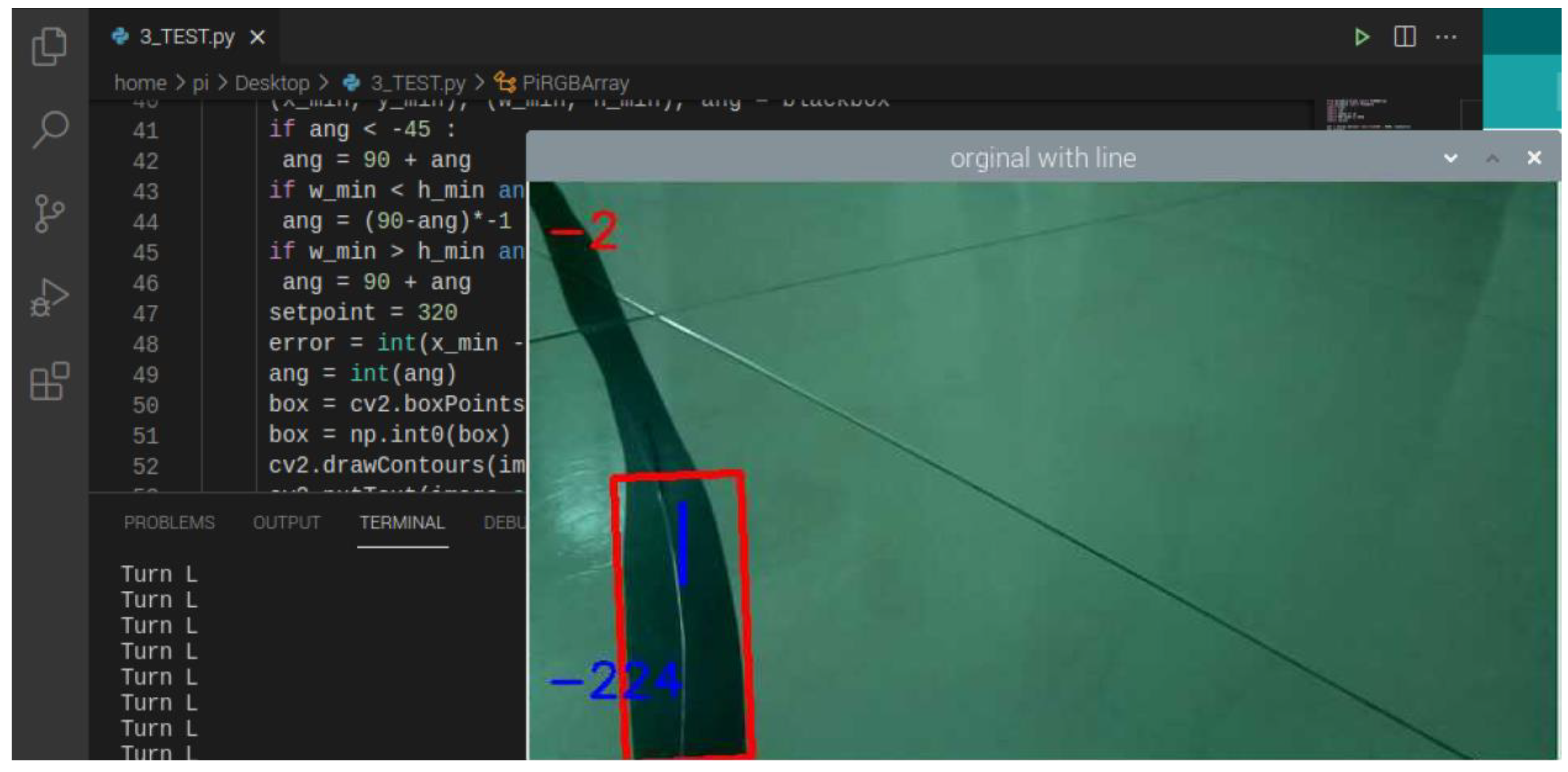
Thankfully, the communication was successful, as shown in Figure 25. Finally, the whole system was run for the first test for full implementation of the robot. However, after running for a few seconds, one of the motors had a spark, leading to a failure in the VESC controller. Furthermore, there were many problems beforehand that will be mentioned in the problems section.
Figure 29.
Result of the final test.
4.2.6. Communication Establishment between Arduino and VESC Controllers
VESC controllers are robust tools to control different kinds of motors. Furthermore, there are several ways for the controllers to receive messages and send the current from the battery to the motor accordingly. One of the most famous ways is the PPM protocol (pulse position modulation). PPM receives PWM signals (pulse width modulation). Also, it has built-in pins for UART protocol. In the end, due to the built-in pins for the UART protocol, it was chosen to communicate between Arduino and VESC controllers. However, the implementation is a bit tricky. Luckily, there is a ready-to-use library in GitHub that is shown in the Appendix.
4.2.7. Controlling Paint Unit Using Arduino
Controlling the paint is divided into two signals. The first is a signal to a relay that is normally open. When a signal of 5V is sent to the relay, it will close, and the compressor will turn on. The other signal is to a servo motor connected to the sprayer trigger. When a PWM signal of a specific angle is sent to the servo, it will rotate accordingly and pull the sprayer trigger. As a result, the servo is delayed by a few seconds from the relay. Hence, when deterioration is detected, the air compressor will turn on. After few seconds, the servo will spray the paint—noting that the delay is an experimental value based on the robot speed.
4.2.8. Localization
The robot was supposed to be localized according to the dead reckoning concept. Thus, it knows how far it moved and its estimated position and forecasted future position based on its speed. However, due to the unreliable encoders in the wheels, the localization was not implemented.
5. Performance Evaluation
5.1. Performance Measures
Measuring the performance will be through dividing each unit of operation and measuring its various outputs. As mentioned in the proposal, these are the performance measures:
- Cognition part performance: measuring the precision of detection and the accuracy of line state recognition.
- Localization/Path planning part performance: measuring localization precision and the path’s deviation.
- Mechanical part performance: calculating the errors from design flows and the efficiency of the system.
- Paint performance: measuring the enhancement to the existing line and the cost analysis of the paint.
5.2. Experimental/Simulation Design
5.2.1. Manufacturing Processes and Assembly
After the design phase, the fabrication phase has started with Aluminum machining and Wooden Wheels’ Mounts fabrication. On the one hand, the aluminum pieces were received with some errors in the cutting length of 4mm. Moreover, it needed threading and drilling in order to connect them. On the other hand, however, mounts were fabricated following the design.
Then, the drive unite connection has been made using soldering techniques and slight connector modifications. In the beginning, batteries were received with a banana plug connector. At the same time, VESC controllers and spark switch had no connectors installed. Moreover, the wheels had a 2 row 3 pins connector, as shown in Figure 30. In the end, all connectors were modified to XT60 male/female connectors to enable plugging/unplugging any part of the connection, as shown in Figure 31.
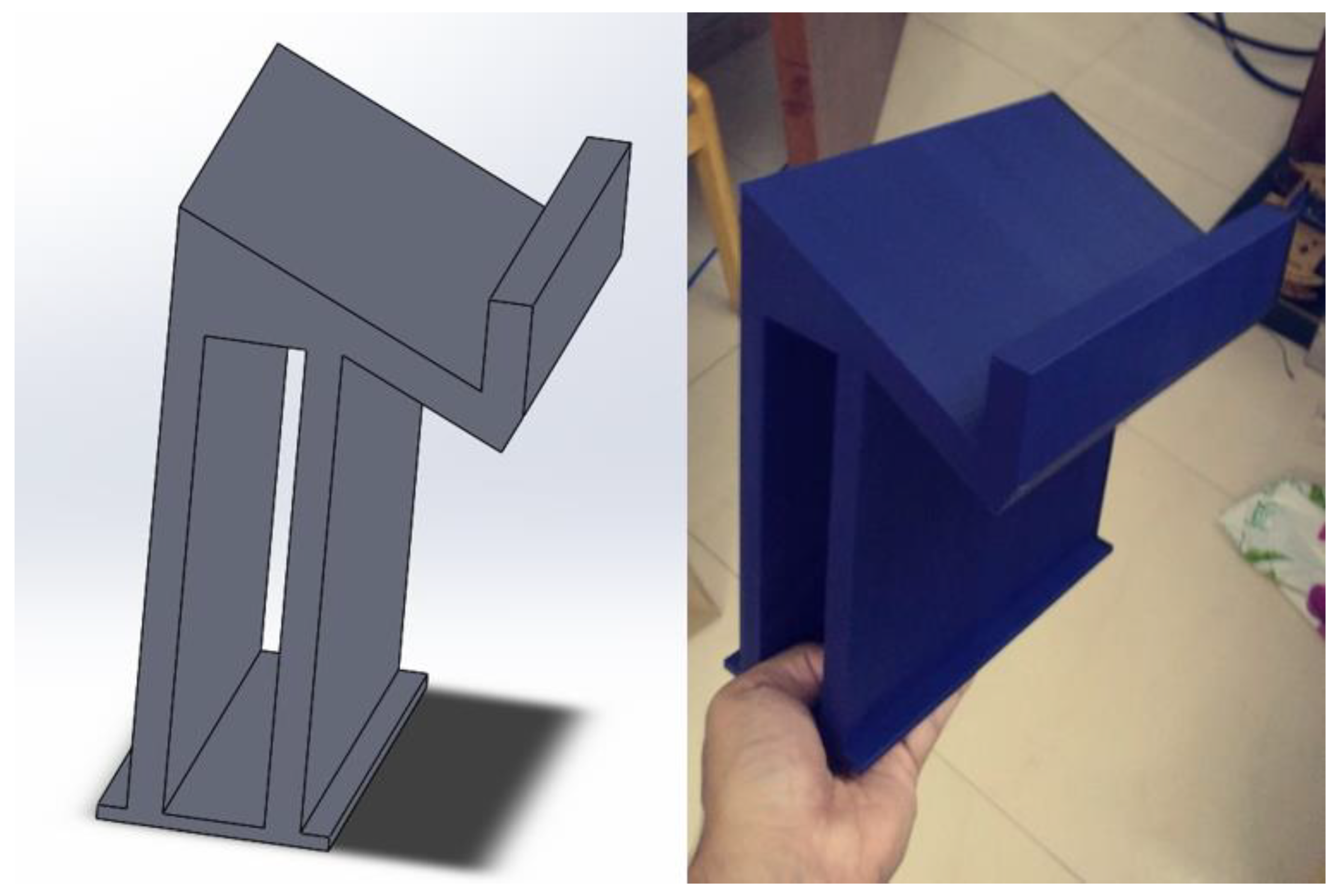
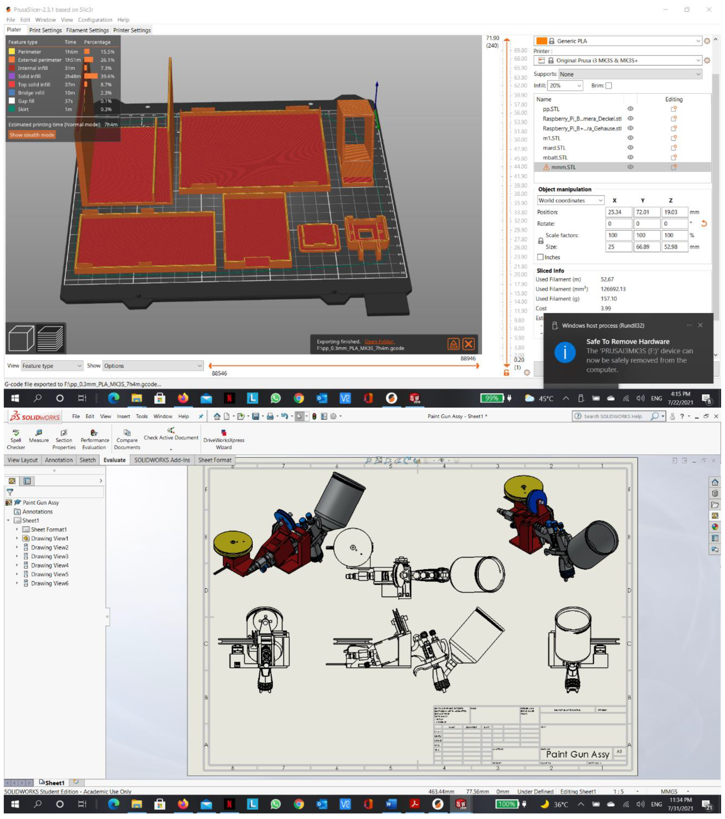
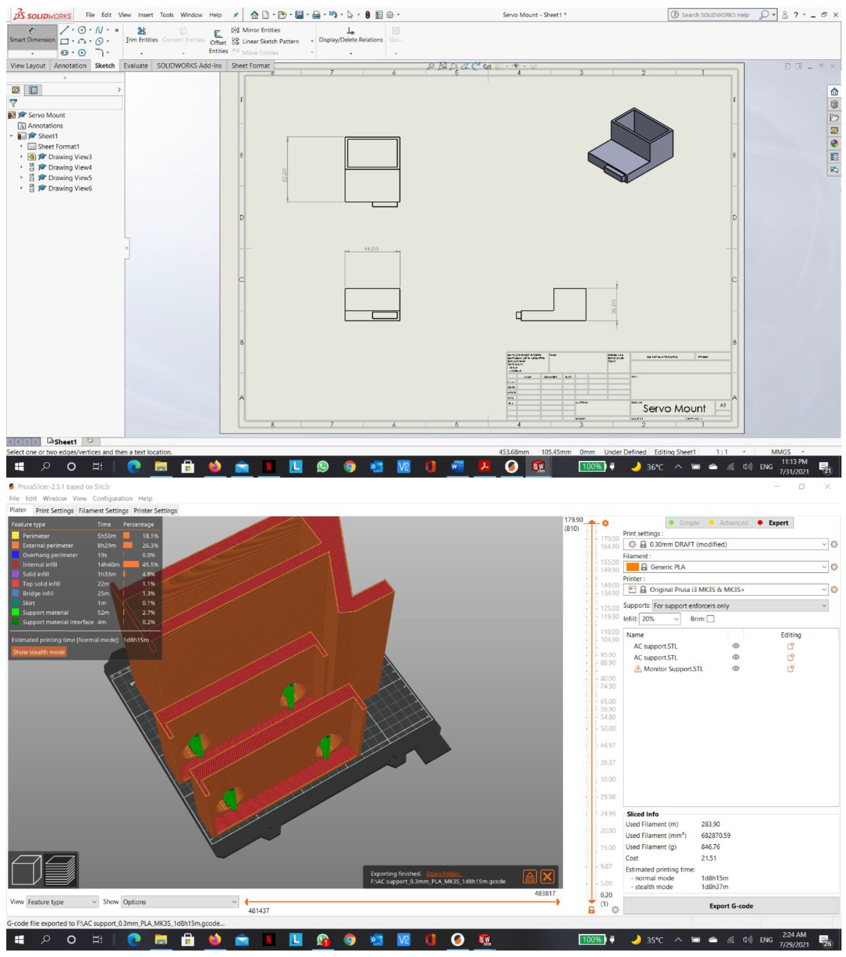
3D Printing
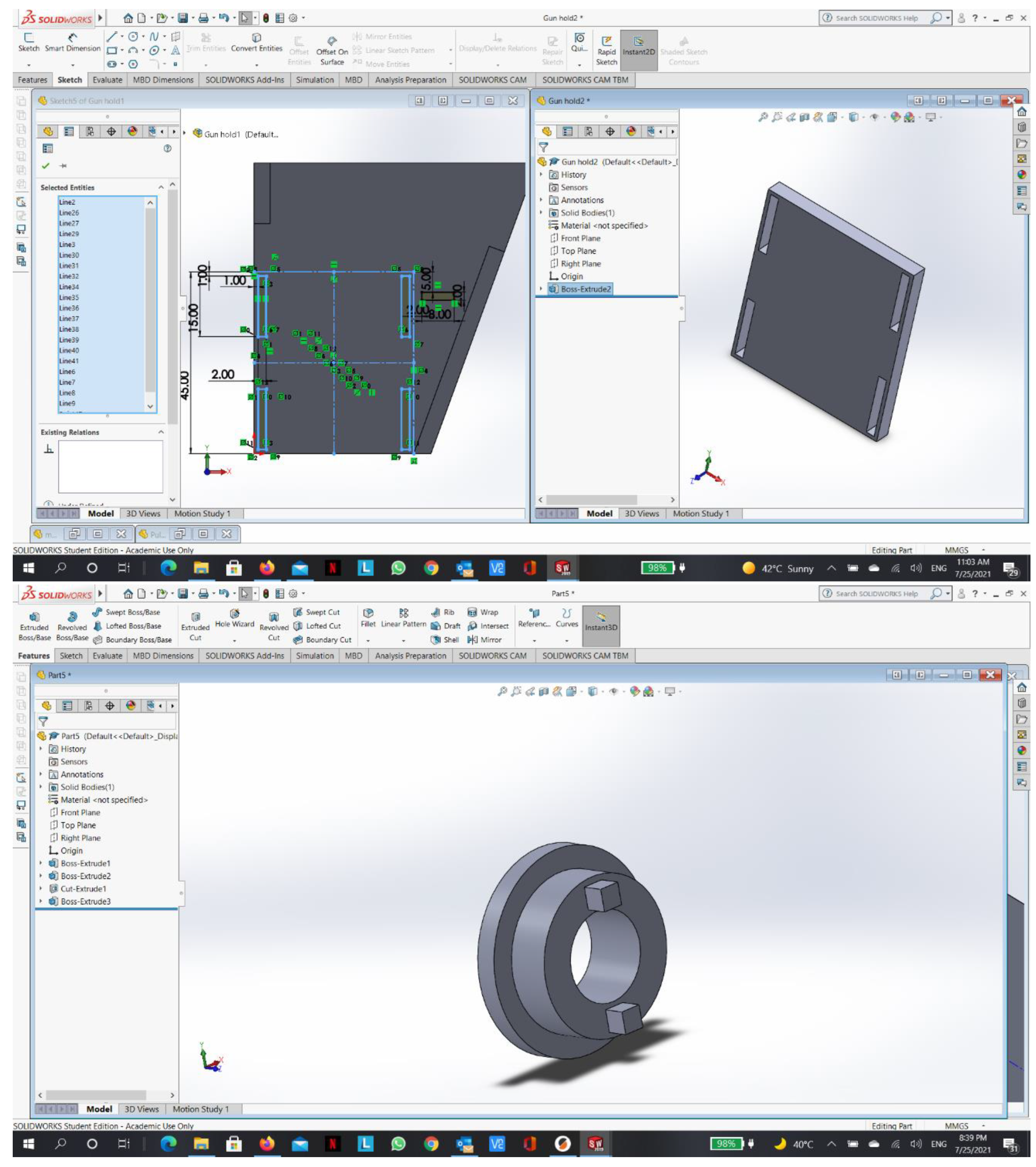
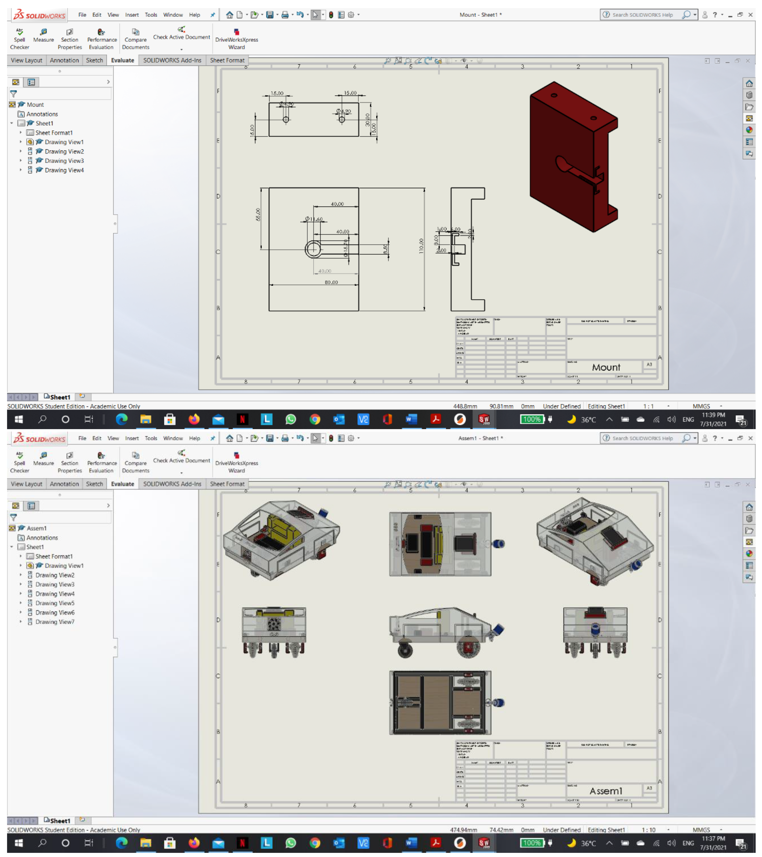
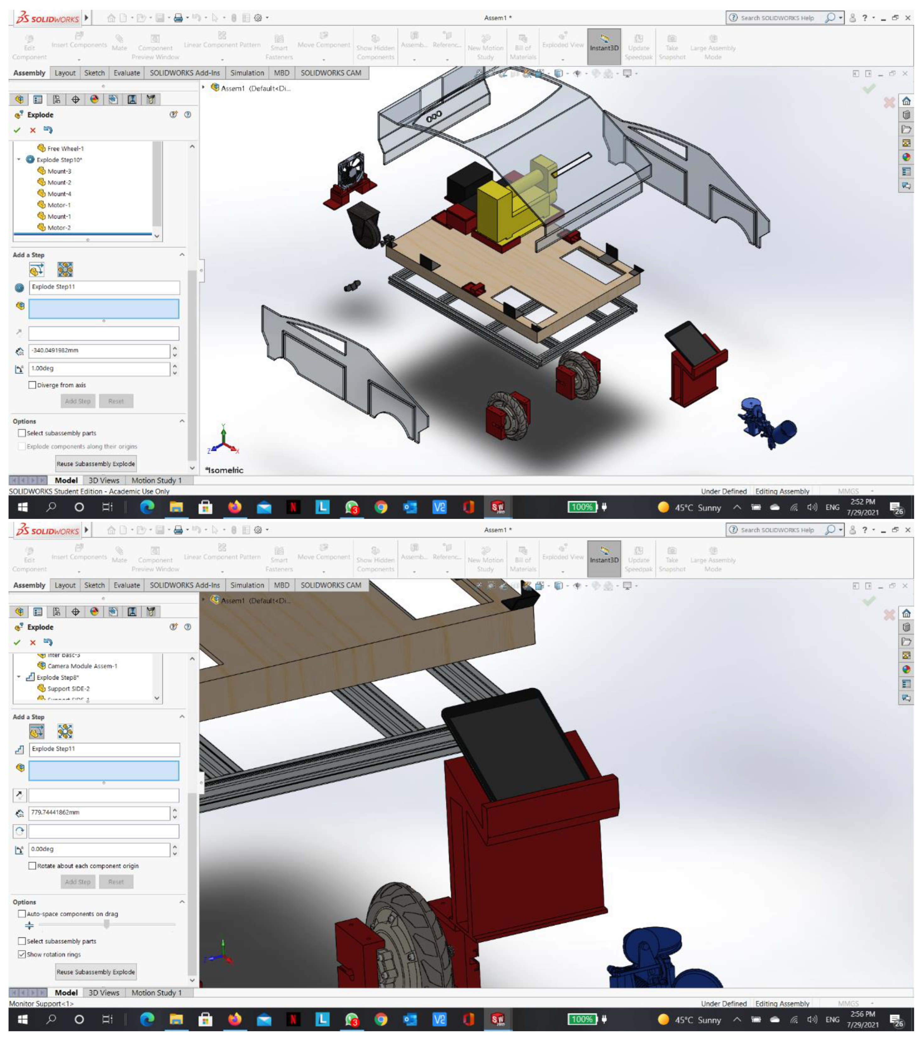
All component mounts to the chassis were designed using SolidWorks software, and then they were printed using PLA+ filament in a 3D printer. Here are some of the designed parts along with the actual prints:
Figure 32.
Wheel mount.
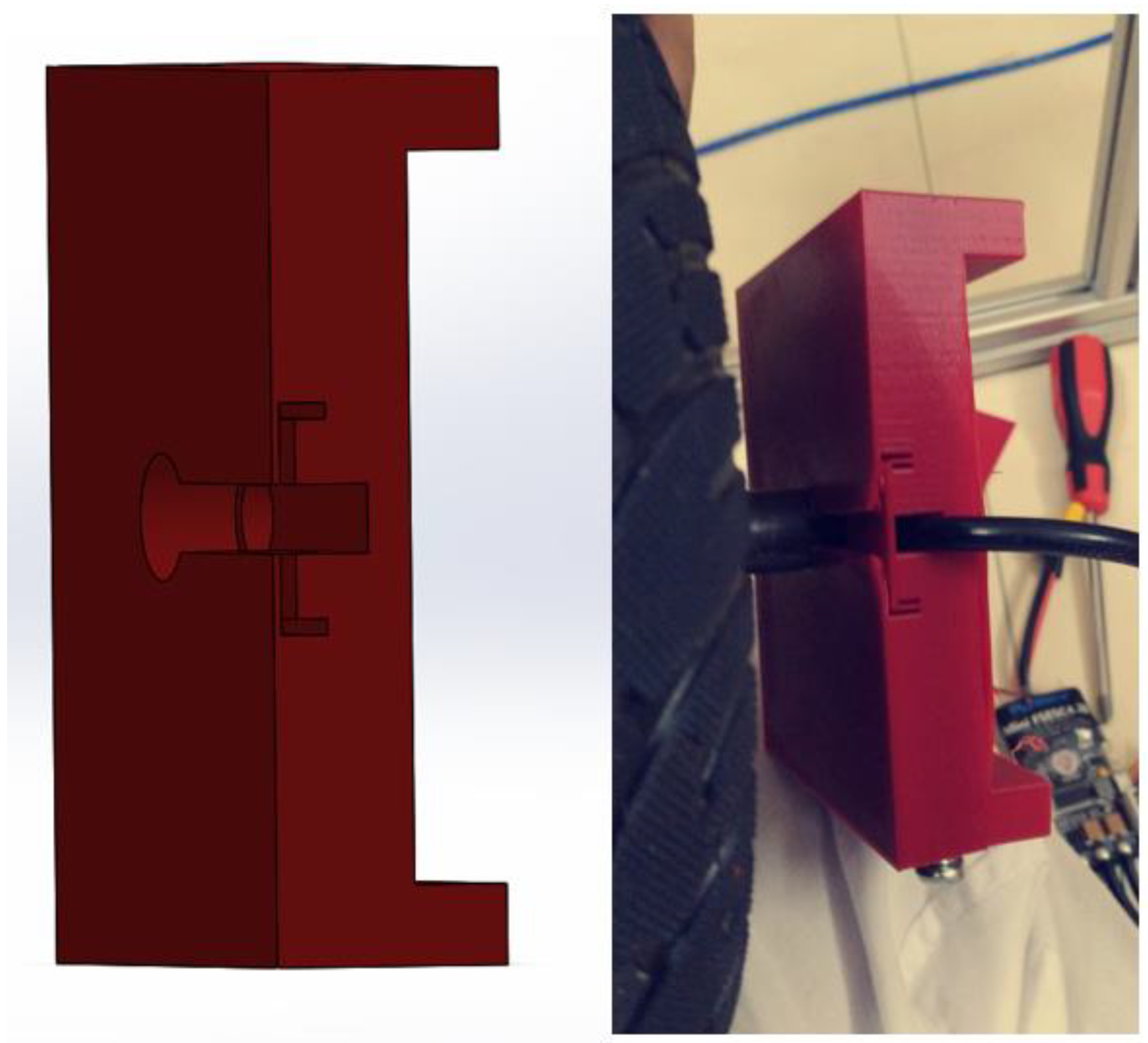
Figure 33.
Sprayer pulley mechanism.
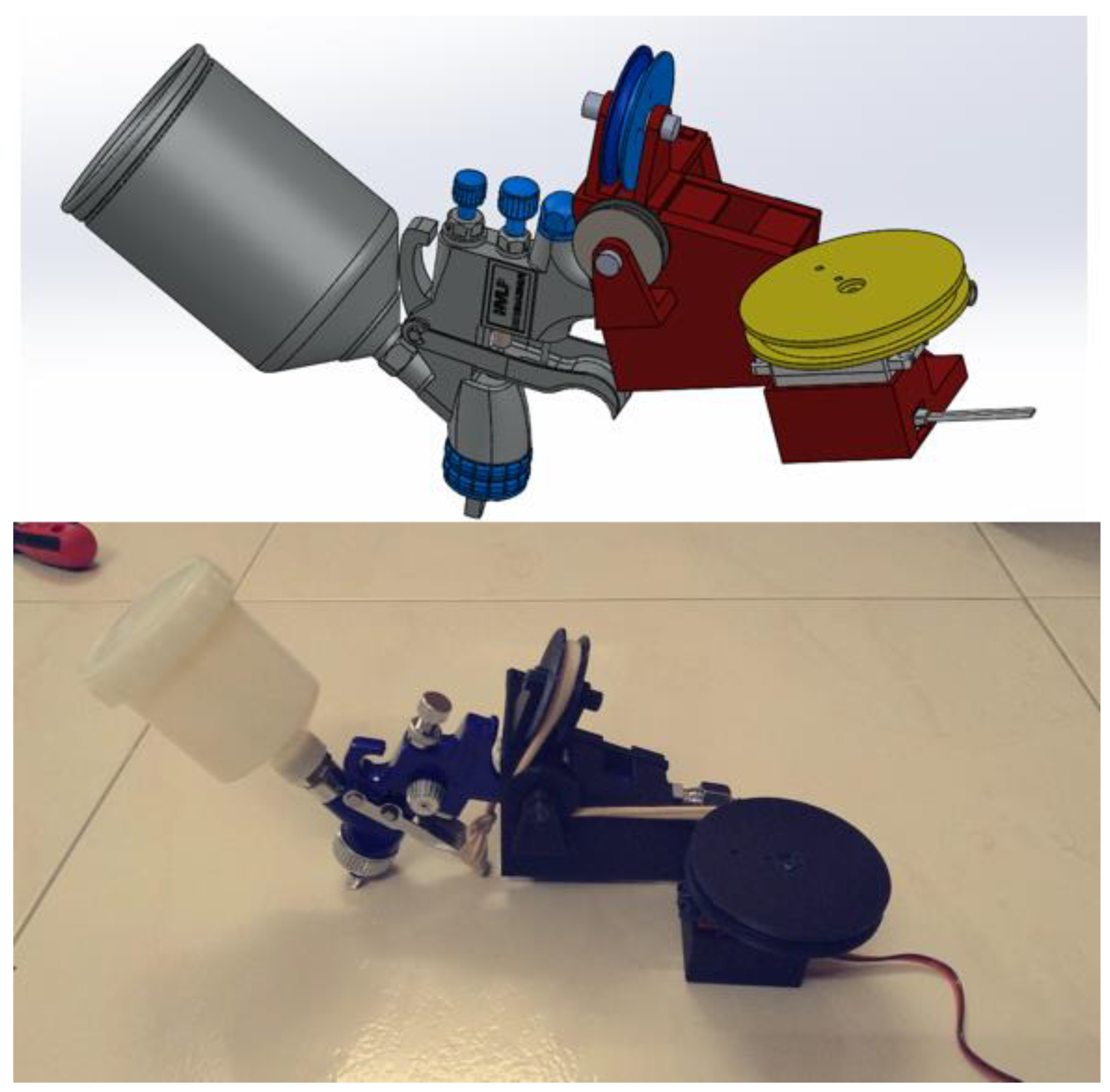
Figure 34.
Monitor and robot ceiling support.
Wiring
5.2.2. Calibration:
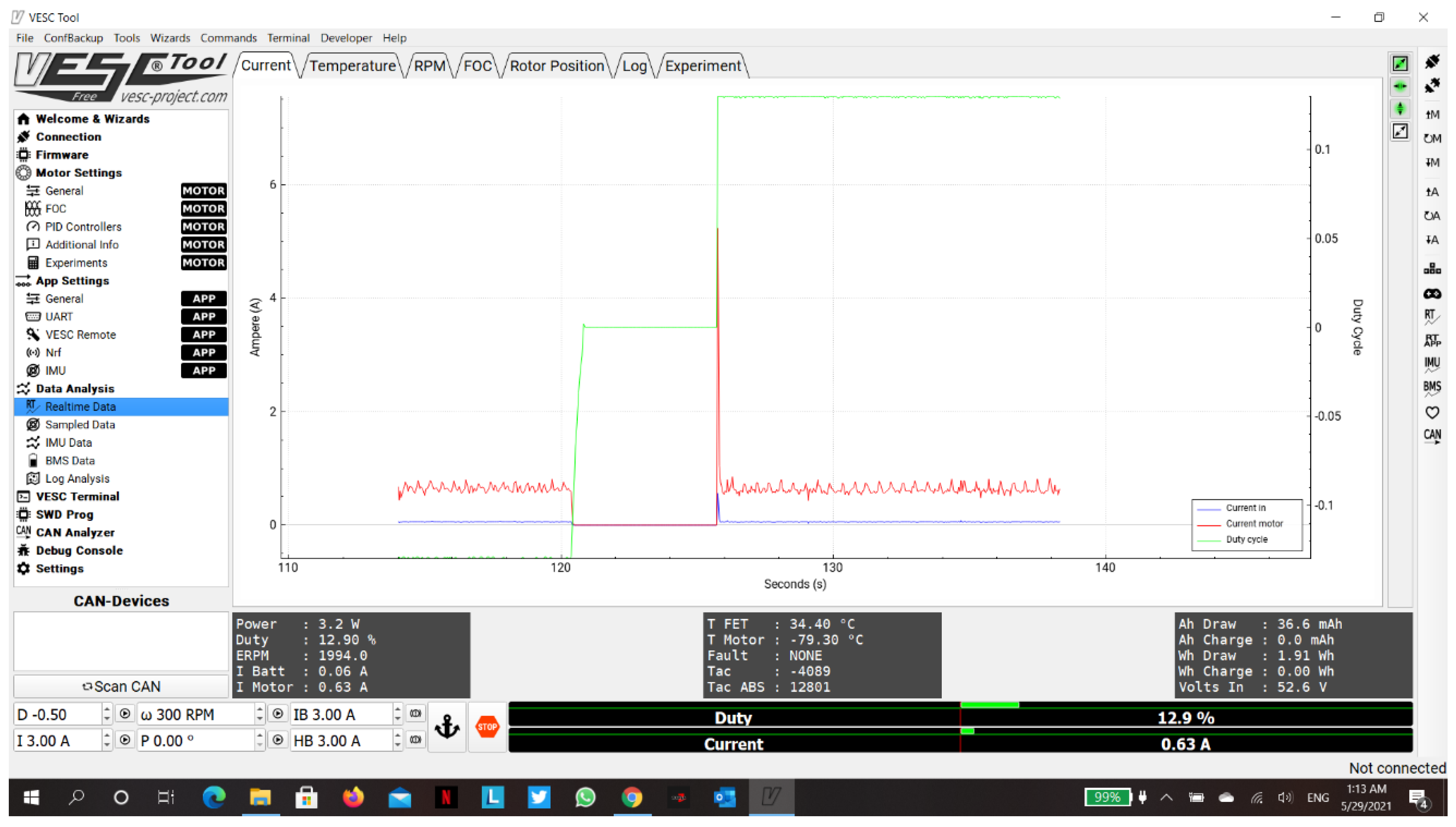
First of all, the drive unit has been tested and calibrated using the VESC tool. VESC tool is a program to control certain types of motor controllers; in our case, it controls Flipsky Mini FSESC4.20 controllers. When calibrating the motors using the VESC tool, the connection was set to a serial connection with a Boud of 9600 bps; the motor settings were configured to be a BLDC motor with hall sensors, max motor current of 10 A, voltage cutoff starts at 36V, maximum rpm of 300, maximum duty cycles of 75%, and a battery of 13s5p Li-ion as shown in Figure 37. Furthermore, the motors were tested after calibration and were controlled using the FSESC controllers; they were calibrated to move in both directions using a serial connection to control the rotation of the motors using current, duty cycles, or rpm inputs. Moreover, FSESC controllers can communicate using digital signals such as UART (serial), or analog signals such as PPM (Pulse Position Modulation), or PWM (Pulse Width Modulation). In the end, the calibration was done using serial communication and VESC tool software; and the real-time data was verified that it could be acquired from the controllers, as shown in Figure 39.
Next, the paint unit servo zero position was calibrated in order to spray with 180 degrees rotation. Finally, the frame was calibrated for weight and balance, as shown in Figure 38.
Figure 37.
VESC tool calibration.
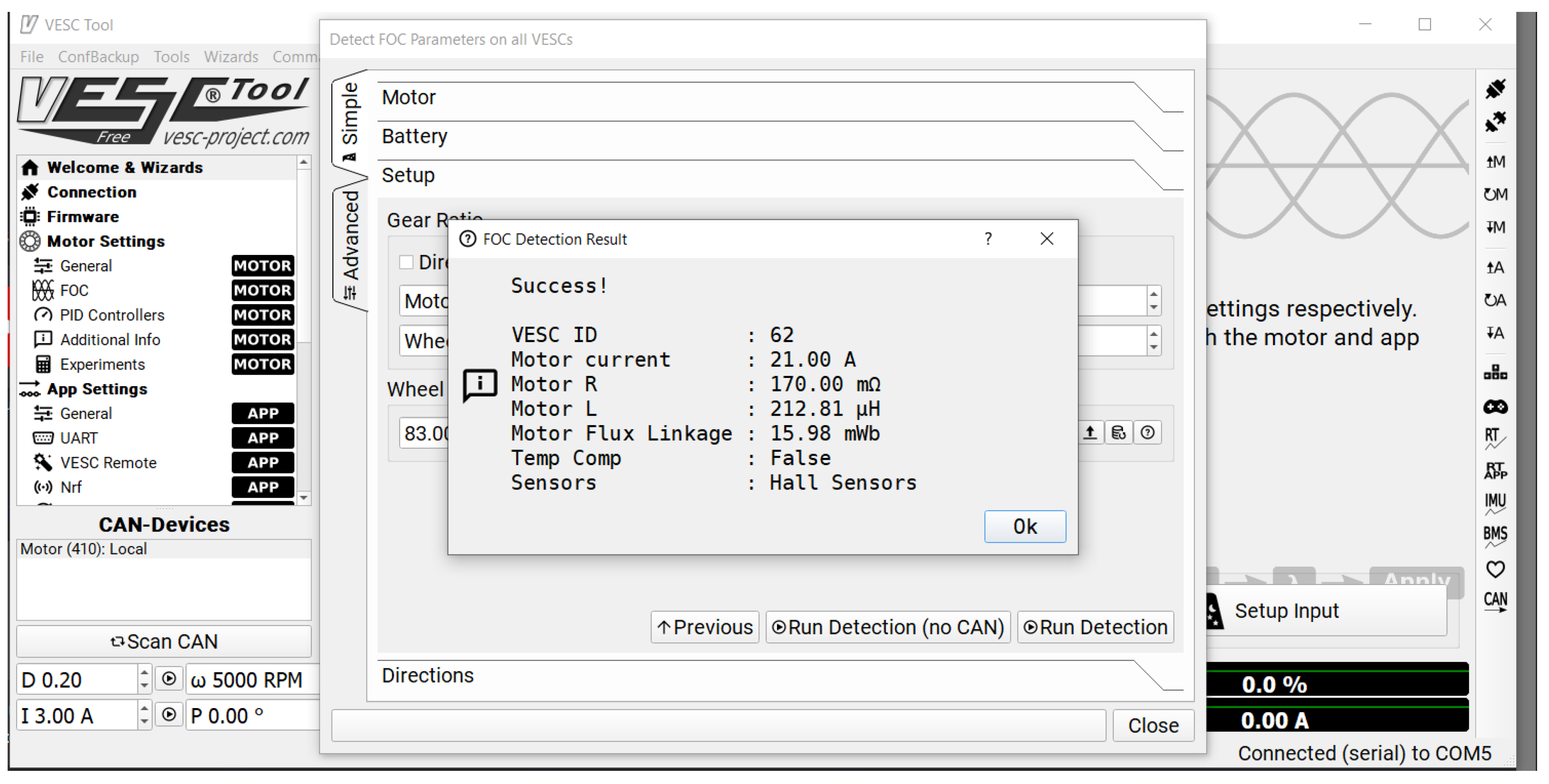
Figure 38.
Robot balance calibration.
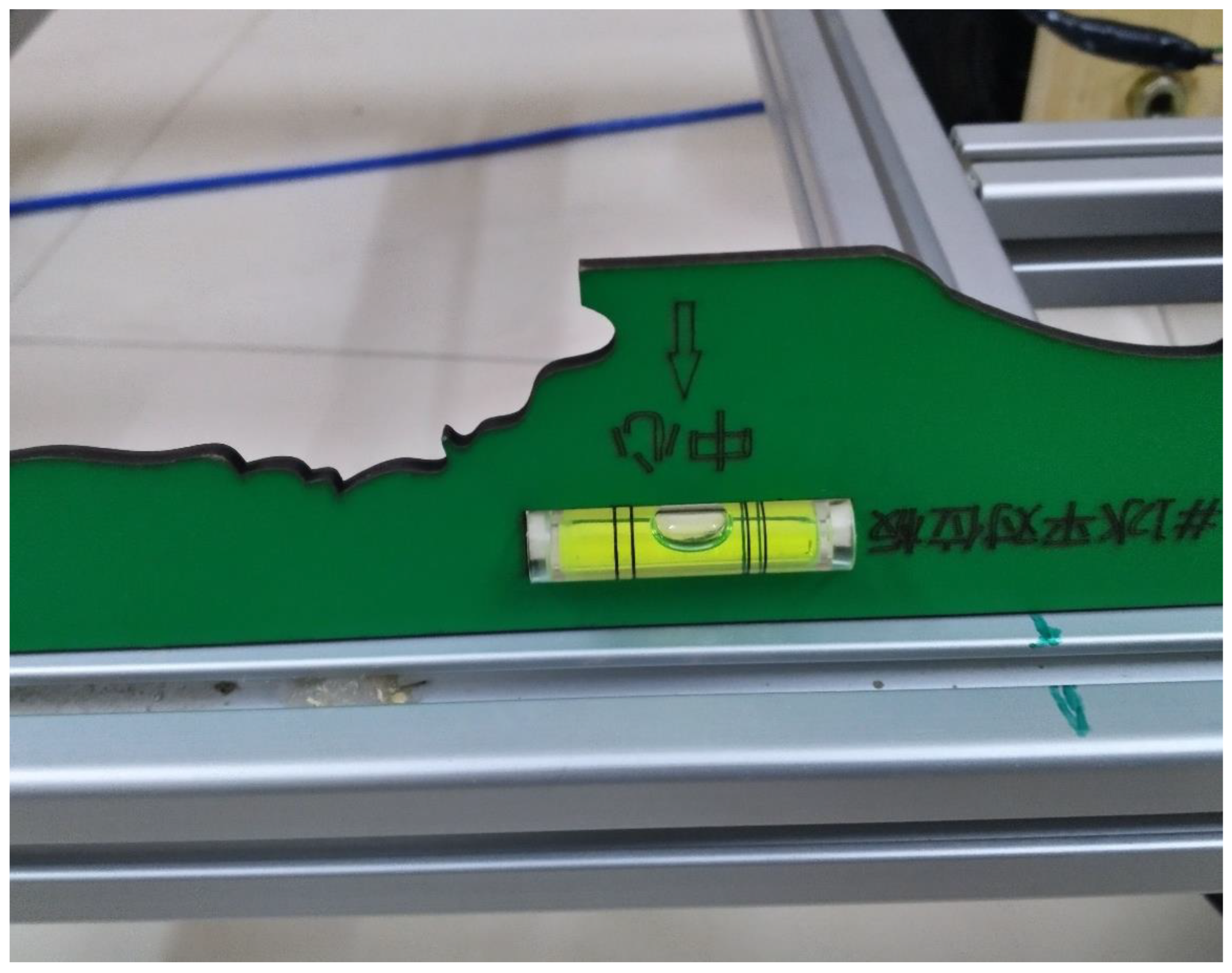
Figure 39.
VESC tool real-time data.
5.2.3. Experiment Design:
Each subsystem was tested individually before assembly. Due to lack of resources, all experiments were to be conducted at home. For example, the painting experiment was designed to be using several valves and sprayers, with water first, then paint. Simultaneously, the motors experiments were supposed to be using different methods of communication. Finally, the entire prototype experiment was set at home with a black line instead of the white line on the asphalt and within a limited space.
5.3. Results and Discussion
In this section, all tests that were conducted will be broken down. Then, there will be a discussion about the results.
5.3.1. Tests Results
The tests were conducted individually for each subsystem as follows:
Motors Tests
Several tests were conducted on the motors, as shown in Table 7. However, after the failure of one of the motors, a new motor with modifications was tested to be successful. The modification will be discussed in chapter 5.3.2.
Painting Tests
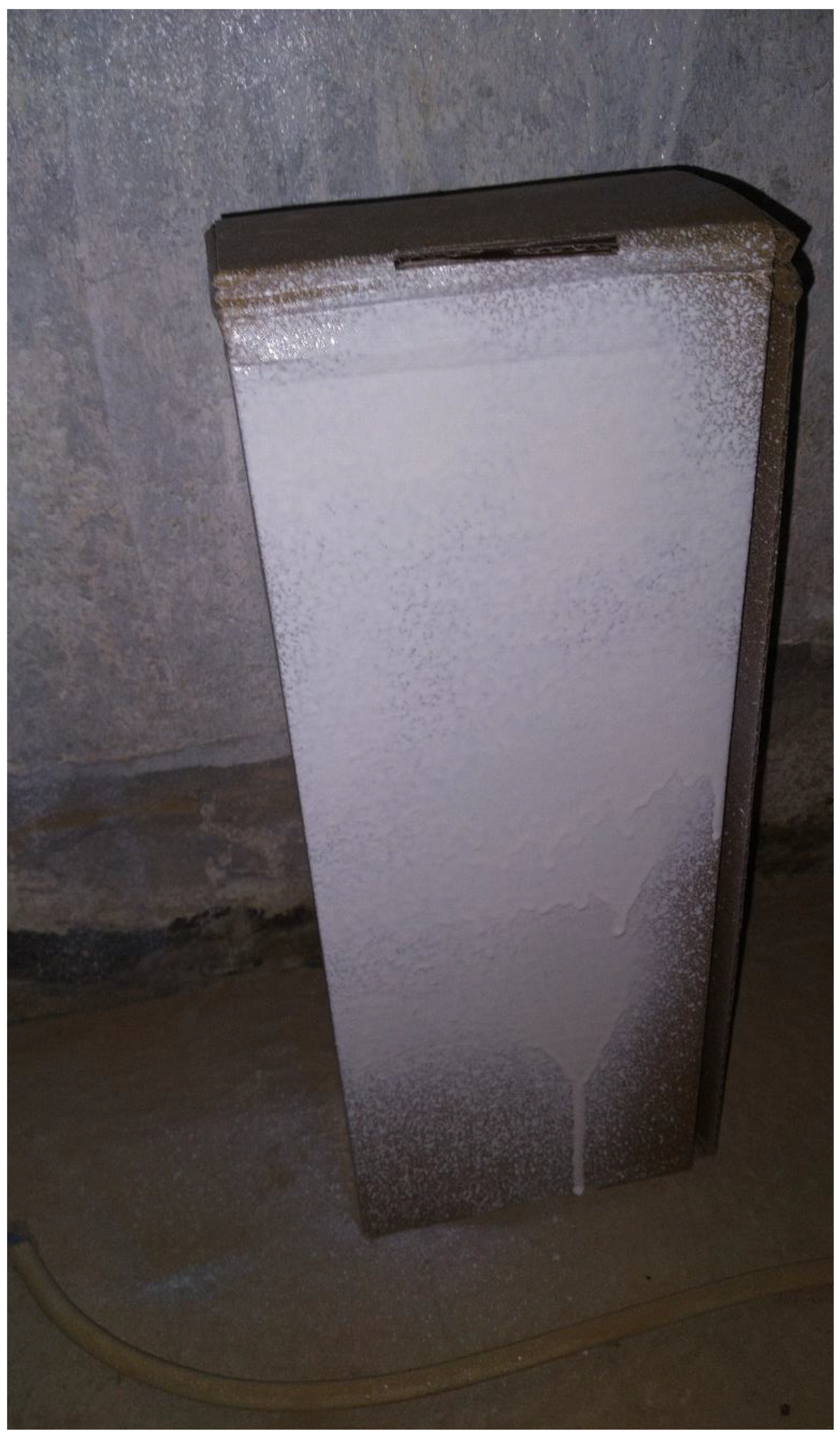
Several paint sprayers were tested, along with two types of solenoid pneumatic valves. The sprayers tested were the gravitational fed sprayer and the conventional siphon fed sprayer. The former has less overspray and a better finish. The latter is easier to use, more efficient with coatings and can be normally-on to make the valve control the flow. Both sprayers are HVLP sprayers and have three nobs for manual control. At first, a conventional sprayer was tested using water and was controlled using Arduino and a Relay. Then, a gravitational fed paint sprayer was tested using paint, Arduino, and a solenoid pneumatic valve. The outcome is illustrated in Figure 30. However, there was a failure in the valve discussed further later in the problems sections. A breakdown of the valve-based tests is shown in Table 8.
Figure 40.
Result of sprayer control test.
Air Compressor and Servo Motor
The air compressor was tested early stage using a relay. It operated as expected. However, the current through the relay was hindered. Then, the new design of the servo motor with the pulley system was tested using several types of strings, fabricated nonwovens, wovens, and small ropes. In which the twisted nylon pulling rope proved to be the most efficient.
Machine Vision Tests
The machine vision was tested through several stages following an online course on the OpenCV library []. The tests were as follows:
Color Detection
Color detection works through the HSV coloring scheme in the OpenCV library, where the image should be converted from RGB coloring format into HSV. After that, the color spectrum’s minimum and maximum limits should be specified to mask it. The HSV spectrum corresponds to Hue, Saturation, and Value, as shown in Figure 41. The result of that test is shown in Figure 42.
Contour Detection
After the color is detected, we need to know its contours and boundaries to know the shape. For that, we can use the Canny filter to separate color from the surrounding. The result of that test is shown in Figure 43.
Points Extraction
Unfortunately, there is no built-in function for boundary points extraction. Therefore, we need to write a function to know how many distinctive boundary points (as in angles), and their locations. The result of that test is shown in Figure 44.
Shape Recognition
After we have detected the contours, we can find the boundary points and then decide the shape of the detected contour. The result of that test is shown in Figure 45.
Color Mean and Standard Deviation
We need to cut the detected shape from the image and apply a mean function available in the OpenCV library in this issue. The result of that test is shown in Figure 46.
Line Following Algorithm
After finding the desired shape, we have calculated the error in the distance from the center of the detected line to the center of the camera frame and then calculated the orientation or the angle error between the vertical line and the centerline of the detection. Moreover, the detected line was cut from the frame to calculate the color mean and standard deviation. The result of that test is shown in Figure 47.
Communication Tests
After the image processing, the RPI needs to send the information to the Arduino to start the motion. In this stage, several tests and errors occurred. In the beginning, the RPI could not communicate with the Arduino, and then with a small random step of printing the serial before the loop, it started to communicate. Then, there was an issue updating the real-time values with the Arduino, where the RPI sends only the initial values. This error turned to be caused by a congestion of data in the serial. Furthermore, it was solved by reducing the information exchanged and delays besides flushing the serial after each frame.
After these steps, the communication was working correctly. However, there were some improvements to the algorithm’s performance that will be discussed in chapter 5.3.2.3.
Full Prototype Tests
After all these tests, the robot was assembled, and all the wires were fixed and checked using the multimeter. Furthermore, individual tests for each subsystem were conducted after assembly. Then, the first full test was conducted on the 22nd of July. Unfortunately, since then, the operation is not efficient enough. Furthermore, a lot of debugging was conducted without much improvement.
5.3.2. Improvements and Modifications:
After testing various functions, several modifications were conducted as follows:
Motors Mounts Improvements
After the failure of one of the motors and installing a new motor, the mounts were modified from wooden mounts that are not precisely fitted into fully designed mounts that are 3D printed, as shown in Figure 48.
Painting Mechanism Modification
After the failure of the valve, another valve was ordered. However, it will not be received before the deadline of the project. Hence, another model for the painting was designed and implemented. More information regarding the new model is in chapter 4.1.1.2.3.
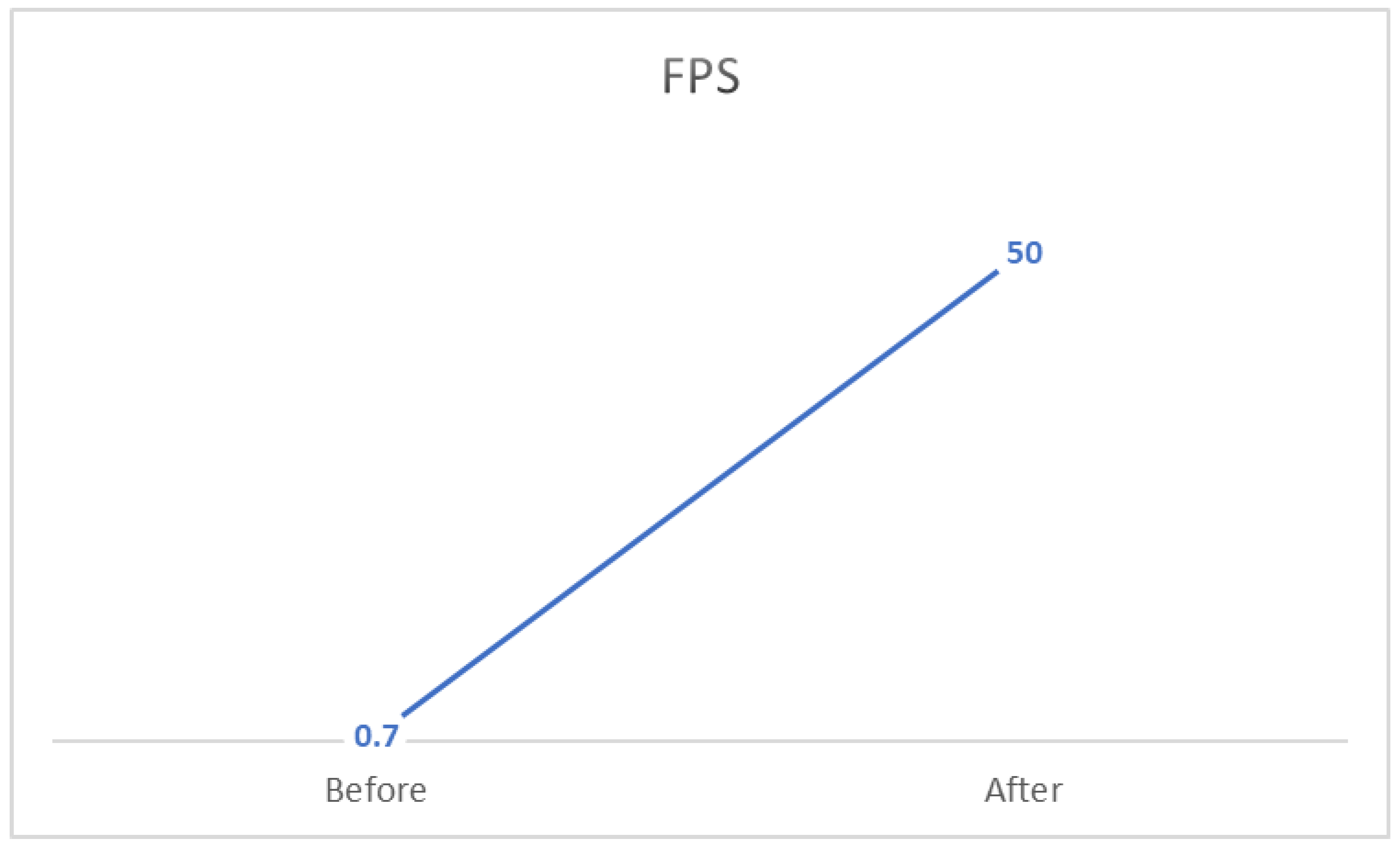
Machine Vision Improvements
After implementing the machine vision algorithm, it was noticed that the performance suffered from a delay. Therefore, I have implemented a counter for each frame. Using the time library in Python, I have calculated the FPS after closing the program by dividing the counter by the time difference from initiating to terminating the program. In the beginning, the FPS was ~0.7. However, through removing unnecessary delays, image processing, communicated information, and reducing the resolution, the FPS has increased to 50, which means an improvement of 7100% on the initial performance.
Performance and UI Improvements
After the full implementation of the robot and testing, there were two noticeable imperfections. One is that the air compressor produces high heat. The other is that RPI requires an internet connection to communicate heedlessly. Therefore, a cooling fan was installed in the robot’s front and connected in parallel with the air compressor to reduce the heat. Also, a tablet is used as a monitor through an HDMI capturing adapter for the user interface.
5.3.3. Discussion
All the tests results had issues at the beginning. However, after debugging and solving most of the issues, we will discuss the system performance based on the following measures:
- Cognition part performance: measuring the precision of detection and the accuracy of line state recognition.
- Localization/Path planning part performance: measuring localization precision and the path’s deviation.
- Mechanical part performance: calculating the errors from design flows and the efficiency of the system.
- Paint performance: measuring the enhancement to the existing line and the cost analysis of the paint.
Cognition Part Performance
In this measure, the performance was highly efficient. Significantly since the algorithm, FPS was highly improved, as illustrated in Fig
Figure 49.
Machine vision performance.
Localization/Path Planning Part Performance
Unfortunately, this is where the robot has a poor performance. The fact that motors encoders are unreliable, and the deviation in wheels specification, makes the dead-reckoning localization flawed. Furthermore, the line following implementation is not accurate, and the performance is unreliable.
Mechanical Part Performance
Thankfully, the mechanical design is solid after the motors mounts modification. All components have 3D-printed mounts that are fixed on the frame. Thus, making the mechanical part excels in performance.
Painting Performance
Unfortunately, after the failure of the original model, the painting model was modified, and it suffers from minor flaws. However, the current model is working correctly, making the performance reasonable.
5.4. Problems and Difficulties
5.4.1. Risk Assessment And Challenges
Several challenges were expected in the process of building this robot. First of all, designing the robot so that painting will not affect the robot’s center of gravity to minimize the power consumption. Furthermore, recognizing an existed line and determining whether it needs to be repainted or not. Also, painting a line while following the road’s path and not deviating was an expected challenge.
The proposal’s risk assessment showed several existing risks, their occurrence probability, and their mitigation plan. The risk assessment is shown in Table 7.
Furthermore, it is worth noting some of the challenges during the project period:
- Parts market research time.
- Finding an assembly of a particular specification or assembling one.
- Misleading parts specifications on the market.
- Weeks 12-15 had the minimum productivity due to term 202 Final exams, Assignment’s submissions, Ramadan last ten days, and the Eid.
- Lead time for some parts was extreme (up to one month).
- Discrepancies on some of the delivered parts, which required extra time to fix.
The major problem was the design criteria and components selection; it is an iterative process that requires some expertise and former knowledge of each unit of the project and its assembly. For example, the initial design of the paint unit had several practical issues that had to be modified. In addition, the frame design and different parts installation and mounting on the frame was a challenge to design without former experience. In addition, some of the misleading information given by the suppliers had an impact. For example, the motorized wheels were exhibited to have a reliable encoder embedded within the wheel’s assemblies; however, it turns out that the encoders suffer from severe noise and are unreliable.
Moreover, the cutting of the frame had some errors in dimension (+2mm) that made the frame require more machining for assembly. Also, parts procurement has been a challenge since there is no specialized store in robotics equipment. Hence, parts procurement took a lot of research and time that was not expected.
The software also had several challenges and difficulties. Starting with configuring the OpenCV library to the RPI, there was no direct way for installing the OpenCV library to RPI. Hence, there is a walk-around that will take approximately 4 hours to complete [25]. Then there was a problem with the wooden mounts, which took around two days to solve since printing took 12 hours. Additionally, there was a failure in one of the tested valves in the paint unit. The valve worked fine for some time, and then it had a minor crack due to poor quality that led to it popping off the hose. Also, several communication errors dragged the progress down because of the troubleshooting difficulty. One of the affiliates was the Node-Red application, an IoT application with a user-friendly interface. However, it was conflicting with the serial communication between the RPI and Arduino. Another affiliate was the throughput of both Arduino and the RPI and their buffers sizes. There was a problem of congestion control that resulted in the drop of messages, and this problem has dragged the progress for several days. Finally, after solving all the issues and testing the whole system, it has run with a bit of a stutter for a few minutes then the motor alongside its VESC was burnt. Finally, the RPI SD card was corrupt in the final stage of the project, which deleted all the previous progress on the RPI.
6. Financial Analysis And Monetary Investments
As part of our project’s analysis, we performed a cost and financial study to adequately analyze our system’s global cost.
We itemized this project’s tangible and intangible costs based upon this notion, having the Saudi Riyal (SAR) as our monetary unit.
In this study, we are not only concerned about the money which was spent to implement this project but also about the energy usage and time flow.
6.1. Project’s Tangible Costs
The achievement of the final output required purchasing several tangible items, namely the necessary electronic components to build our robot.
Table 8 shows the costs of the items used in the robot.
6.2. Project’s Intangible Costs
In addition to the tangible costs and expenses, this project is also composed of intangible demands. The latter involves time and energy.
The project started on the 4th of February and was completed on the 4th of August, totaling 24 weeks of working time. Furthermore, the time expenditure can be formalized in the task and the total time spent in hours. Table 9 quantifies those intangible costs in numbers.
Table 9.
Risk assessment.
| Risk | Probability | Mitigation Plan | Occurrence |
| Materials Delay | Mid | Purchase from other vendors (Higher cost), Or Fabrication (Time consuming) |
Yes, valves, RPI accessories, 3D printer, and RPI camera had a delay issue. At the same time, the ordered batteries were not delivered completely. |
| The debugging phase will take more time | High | Ask for guidance, or consult experienced people Plan for more debugging time |
Yes, many issues were installing the Raspian OS and debugging, along with debugging issues in communication. Also, multiple tests failures elongated debugging and troubleshooting. |
Table 10.
Risks that were not expected.
| Risks that were not considered | Occurrence |
| Materials reliability issues | Multiple acquired parts had a reliability issue, such as the motors from the local market. |
| Ordered parts specifications | Multiple parts were designed and ordered to meet certain specifications; however, the delivered parts had an error, such as dimension error on the frame. |
Table 11.
Tangible cost and expenses.
| Components | Cost | Tools | Cost | Failed components | Cost |
| Frame | 972 | 3D printer | 3767 | Failed motor | 210 |
| Cardboard | 140 | 3D printer Filaments | 506 | Failed Valves | 398 |
| Motors | 350 | Multimeter | 30 | Failed SD card | 73 |
| Castor Wheel | 22 | Battery Chargers | 50 | ||
| Arduino Mega | 158 | Soldering station | 573 | ||
| Raspberry Pi 4 | 549 | Fastening tools + Tap | 192 | ||
| Raspberry Pi Camera | 79 | ||||
| Raspberry Pi Accessories | 410 | ||||
| VESC | 1107 | ||||
| Servo motor | 93 | ||||
| Relay (on Arduino electronics kit) | 472 | ||||
| Air compressor | 250 | ||||
| Paint sprayer | 126 | ||||
| Batteries | 1020 | ||||
| Switches | 209 | ||||
| Connectors | 543 | ||||
| Cooling fan | 20 | ||||
| Monitor | 470 | ||||
| HDMI capture | 69 | ||||
| 7014 | 5118 | 681 | |||
| 12813 SAR | |||||
Table 12.
Time consumption.
| Task | Time spent |
| Design | There are 197 fully designed drawings using SolidWorks, with a minimum of 30 min per drawing. Moreover, approximating the average of drawing to be 2 hours, the total time spent designing would be approximately 400 hours. |
| Local market search | The local searching was conducted in both Jeddah and Riyadh. The search was for different components at the time. Moreover, there were ten times in which the search was done through an entire day. Hence, the time would be approximated as 60 hours. |
| Machining | Machining was done at the beginning on the aluminum frame, and it took around two days. Therefore, approximately 12 hours. |
| Soldering | Soldering was done two times, the first was at the beginning, and the second was after the failure of the motor. The first took much more time due to practicing, whereas the second time took around 6 hours. Therefore, the total approximated time is 24 hours. |
| Printing | Based on the log files of the 3D printer, the total time of printing is 158.9 hours. |
| Assembly | Assembling was done multiple times, approximately five times. However, the majority took around half a day, whereas the final assembly took three full days. Therefore, the approximated time is 40 hours. |
| Programming | Programming was the most consuming out of all the tasks, especially since the SD card has failed at a late stage which made me repeat all the setup of the RPI and programing. However, the approximated time spent programming and troubleshooting daily from week 13 to week 19 was half an hour daily, totaling 21 hours. Nevertheless, from week 19 to week 23, the programming intensified and troubleshooting to approximately 3 hours daily, totaling 105 hours. Therefore, the approximated time spent is 126 hours. |
| Testing & debugging | Testing has started since Week 13 with the motors and painting. First, the motors were tested using VESC, then Arduino, and finally RPI. Each test was conducted approximately three times, and each time took around half an hour, totaling approximately 5 hours. Additionally, painting testing took approximately the same time. At the same time, the prototype testing and debugging took two whole weeks. Therefore, the estimated time spent is approximately 122 hours. |
| Total | ~940 hours ( ~39 days) |
7. Conclusion and Future Directions
7.1. Limitations
There are several limitations to this particular robot that could be removed in future development. One of the limitations is the painting unit sub-assembly. In addition, the painting pattern adjustment is manual using the sprayer knobs, where in the future, a specific sprayer could be designed with automated adjustment of the paint pattern. Another limitation is the color of the paint. Since we use only one sprayer with one paint container, it goes without saying that there is only one paint option. However, an enhanced sprayer could be developed with several channels of paints. Also, the sprayer placement is fixed on the robot, wherein an enhanced version could be moving to several locations.
Furthermore, the chassis has limitations also. First of all, it is exposed to sun, rain, and dust, which could sabotage the robot electronics. Also, it is vulnerable to shocks and damage. Finally, it does not have a suspension system to minimize vibration and move above road ramps.
Another primary limitation is the ability to clean the painting location before attempting to paint. This limitation can be removed by integrating a blower into the robot.
Also, obstacle avoidance is a limitation in this model since the robot can not avoid an obstacle in its path, nor can it return to the path after avoiding it.
Finally, the robot is limited since it requires human interference for recharging, powering on-off, and cleaning. Furthermore, the sprayer requires usual maintenance to avoid nozzle clogging with paint.
7.2. Future Development
There are two main products idea that is planned and could potentially be developed from this novel idea:
7.2.1. Fully Autonomous and Robust Road Maintenance Robot
This product will offer a solution for more than road paint. It can clean the road, repaint road lines, paint a new road line, refill asphalt cracks, and water the plant on the side road. It is an ambitious vision but achievable.
This robot could be an industrial robot with multiple chambers for paint, asphalt, thinners, and a heated solvent to lower the viscosity of the fluids and avoid clogging. Then, depending on the task, a particular chamber will be armed along with its correlated sprayer.
7.2.2. Fully Autonomous and Robust Industrial Painting Robot
This product will offer a solution for any industrial painting where the robot will have a robotic manipulator for painting. Furthermore, the robot is capable of painting vehicles, roads, houses, and products. For example, this robot could be in a room that needs to be painted, and after the user communicates the desired paint design, the robot will start painting the room as designed. Furthermore, if the robot was in a car painting shop, it will recognize the car model autonomously and start painting the car surface with the desired color.
7.3. Conclusion:
In conclusion, this project faced many challenges along the way. Nonetheless, the robot was built by one person in his house with limited resources and time. The idea behind the project is a new idea that has not been implemented before. Therefore, I am proud of the outcome, even though it did not work as expected. My aim from the beginning was to deliver an autonomous robot capable of recognizing lines patterns and repainting the lines, programming codes, and a final report showing a detailed description of the robot mechanism. Hence, the deliverables were as follows:
- Design drawing
- Physical operational product
- Programming codes
- A detailed document of the project
These deliverables were stated in the proposal. Fortunately, all of them have been delivered successfully.
Acknowledgments
With great pleasure, I would like to express my gratitude to the people who significantly helped me throughout this journey and whose valuable assistance has brought this project to be. First and foremost, I would like to present my warmest thanks to my colleague Eng. Salam Al-Saif for his assistance after the failure of one motor during a test. Also, to my advisor Dr. Uthman Baroudi for his dedicated follow-up and support throughout the project. Furthermore, my family’s assistance was the most significant in motivating the process of the project. Hence, I would like to seize this opportunity to extend my thanks to my little family, namely my parents and my siblings, who were supportive of me throughout my journey. It is also my pleasure to thank my friends and colleagues in SAUDIA AIRLINES who have continuously supported me, namely, Mr. Talal Al-Ammari, for his support during the parts acquiring phase from the local market.
Appendix A - Materials characteristics
Aluminum extrusions:
3D prints:
The printed parts are made of PLA+ filament. PLA+ are extracted and purified from corn grain; High rigidity, good glossiness, and transparency; Toughness is ten times more than PLA. Not susceptible to cracks. It has the following properties:
- ○
- softening temperature: 50 °C.
- ○
- Rockwell hardness: R70-R90.
- ○
- Elongation at failure: 3.8%
- ○
- flexing strength: 55.3 MPa.
- ○
- Tensile breaking strength: 57.8 MPa.
- ○
- Modulus of longitudinal elasticity: 3.3 GPa
Appendix B - Initial Design
Appendix C - Final 3D CAD drawings
Appendix D - RPI python code:
from picamera.array import PiRGBArray
from picamera import PiCamera
import time
import cv2
import numpy as np
import RPi.GPIO as GPIO
import serial
ser = serial.Serial(‘/dev/ttyUSB0’, 115200, timeout=1)
ser.flush()
GPIO.setmode(GPIO.BOARD)
GPIO.setup(40, GPIO.OUT)
GPIO.output(40, GPIO.HIGH)
camera = PiCamera()
camera.resolution = (200, 125)
camera.rotation = 0
camera.framerate = 60
rawCapture = PiRGBArray(camera, size=(200, 125))
time.sleep(0.1)
kernel = np.ones((3, 3), np.uint8)
x_last = 100
y_last = 80
# To initiate Serial:
line = ser.readline().decode(‘utf-8’).rstrip()
print(line)
time.sleep(1)
# To calculate FPS:
start_time = time.time()
counter = 0
for frame in camera.capture_continuous(rawCapture, format=“bgr”, use_video_port=True):
counter +=1
image = frame.array
Blackline = cv2.inRange(image, (0, 0, 0), (65, 65, 65))
Blackline = cv2.erode(Blackline, kernel, iterations=1)
# Blackline = cv2.dilate(Blackline, kernel, iterations=9)
img_blk, contours_blk, hierarchy_blk = cv2.findContours(Blackline.copy(), cv2.RETR_TREE, cv2.CHAIN_APPROX_SIMPLE)
# For error
contours_blk_len = len(contours_blk)
if contours_blk_len > 0:
if contours_blk_len == 1:
blackbox = cv2.minAreaRect(contours_blk[0])
else:
candidates = []
off_bottom = 0
for con_num in range(contours_blk_len):
blackbox = cv2.minAreaRect(contours_blk[con_num])
(x_min,y_min),(w_min,h_min),ang=blackbox
box = cv2.boxPoints(blackbox)
(x_box,y_box)=box[0]
if y_box > 120:
off_bottom +=1
candidates.append((y_box,con_num,x_min,y_min))
candidates = sorted(candidates)
if off_bottom > 1:
candidates_off_bottom=[]
for con_num in range((contours_blk_len-off_bottom),contours_blk_len):
(y_highest,con_highest,x_min,y_min)=candidates[con_num]
total_distance = (abs(x_min-x_last)**2 + abs(y_min-y_last)**2)**0.5
candidates_off_bottom.append((total_distance,con_highest))
candidates_off_bottom=sorted(candidates_off_bottom)
(total_distance,con_highest) = candidates_off_bottom[0]
blackbox = blackbox = cv2.minAreaRect(contours_blk[con_highest])
else:
(y_highest,con_highest,x_min,y_min)=candidates[contours_blk_len-1]
blackbox = cv2.minAreaRect(contours_blk[con_highest])
(x_min, y_min), (w_min, h_min), ang = blackbox
if ang < -45:
ang = 90 + ang
if w_min < h_min and ang > 0:
ang = (90 - ang) * -1
if w_min > h_min and ang < 0:
ang = 90 + ang
setpoint = 100
error = int(x_min - setpoint)
ang = int(ang)
mean = np.average(image[int(x_min):int(x_min)+int(w_min),int(y_min):int(y_min)+int(h_min)])
std = np.std(image[int(x_min):int(x_min)+int(w_min),int(y_min):int(y_min)+int(h_min)])
print(“mean is : “+str(mean))
print(“std is : “+str(std))
paint=255-mean*std-40
if paint < 0:
paint = 1
else:
paint = 0
box = cv2.boxPoints(blackbox)
box = np.int0(box)
cv2.drawContours(image,contours_blk,-1,(0,255,0),3)
cv2.drawContours(image, [box], 0, (0, 0, 255), 3)
cv2.putText(image, str(ang), (10, 20), cv2.FONT_HERSHEY_SIMPLEX, 1, (0, 0, 255), 2)
cv2.putText(image, str(error), (10, 90), cv2.FONT_HERSHEY_SIMPLEX, 1, (255, 0, 0), 2)
cv2.line(image, (int(x_min), 60), (int(x_min), 80), (255, 0, 0), 3)
ser.write(“E” + str(error) + “A” + str(ang) + “S” + str(paint) + ‘\n’)
# print(“TEST” + str(error)+”Angle” + str(ang))
# line = ser.readline().decode(‘utf-8’).rstrip()
# print(line)
# ser.flush()
cv2.imshow(“orginal with line”, image)
rawCapture.truncate(0)
key = cv2.waitKey(1) & 0xFF
if key == ord(“q”):
break
finish_time = time.time()
fps = counter / (finish_time-start_time)
print (“frames per second = “+str(fps))
GPIO.output(40, GPIO.LOW)
Appendix E - Arduino C++ code:
#include <VescUart.h>
#include <buffer.h>
#include <datatypes.h>
#include <crc.h>
#include <buffer.h>
#include <crc.h>
#include <datatypes.h>
#include <VescUart.h>
#include <Servo.h>
#define Relay 3
Servo myservo;
int pos = 0;
int Error, Angle, LRPM, RRPM;
float k1, k2;
VescUart RUART, LUART;
void setup() {
//Relay
pinMode(Relay, OUTPUT);
//Servo
myservo.attach(9);
// RPI & MOTORS:
Serial.begin(115200);
Serial1.begin(115200);
Serial2.begin(115200);
while (!Serial1) {
;
}
while (!Serial2) {
;
}
RUART.setSerialPort(&Serial2);
LUART.setSerialPort(&Serial1);
}
void loop() {
// digitalWrite(Relay,LOW);
// delay(10000);
//digitalWrite(Relay,HIGH);
// delay(10000);
//myservo.write(-180);
//for (pos = 0; pos <= 100; pos += 1) { // goes from 0 degrees to 180 degrees
// // in steps of 1 degree
// myservo.write(pos); // tell servo to go to position in variable ‘pos’
// delay(15); // waits 15ms for the servo to reach the position
// }
// for (pos = 100; pos >= 0; pos -= 1) { // g oes from 180 degrees to 0 degrees
// myservo.write(pos); // tell servo to go to position in variable ‘pos’
// delay(15); // waits 15ms for the servo to reach the position
// }
// RUART.setDuty(0);
// LUART.setDuty(0);
// Control gains:
k1 = 0.5;
k2 = 0.7;
Serial.flush();
if (Serial.available() > 0) {
// read from RPI:
String dataIn = Serial.readStringUntil(‘\n’);
//Serial.println(dataIn);
// Decode:
int Err = (dataIn.substring( dataIn.indexOf(‘E’) + 1 , dataIn.indexOf(‘A’) )).toInt();
int Ang = (dataIn.substring( dataIn.indexOf(‘A’) + 1 , dataIn.indexOf(‘S’) )).toInt();
int paint = (dataIn.substring( dataIn.indexOf(‘S’) + 1 )).toInt();// * -1;
//Serial.print(ER);
//Serial.println(x);
//Serial.print(AN);
//Serial.println(y);
RPM(0.02, (Err * k1) + (Ang * k2));
Paint(paint);
RUART.printVescValues();
LUART.printVescValues();
}
if ( RUART.getVescValues() ) {
Serial.print(“Right Motor RPM”);
Serial.println(RUART.data.rpm);
// Serial.println(RUART.data.inpVoltage);
// Serial.println(RUART.data.ampHours);
// Serial.println(RUART.data.tachometerAbs);
}
if ( LUART.getVescValues() ) {
Serial.print(“Left Motor RPM”);
Serial.println(LUART.data.rpm);
// Serial.println(LUART.data.inpVoltage);
// Serial.println(LUART.data.ampHours);
// Serial.println(LUART.data.tachometerAbs);
}
}
void RPM(float Speed, float Steering) {
// Differental drive
if (Angle == 0) {
RUART.setDuty(Speed);
LUART.setDuty(Speed);
return;
}
else if ( Steering > 0) {
Steering = 100 - Steering;
RUART.setDuty(Speed);
LUART.setDuty(Speed * Steering / 100);
return;
}
else if ( Steering < 0) {
Steering = Steering * -1;
Steering = 100 - Steering;
LUART.setDuty(Speed);
RUART.setDuty(Speed * Steering / 100);
return;
}
//
// if (Error > 100) {
// RRPM=0;
// LRPM=0;
// Serial.println(“Out of scope”);
// }
// else if (Angle < 0) {
// if (Error > 0) {
// RRPM = 200;
// LRPM = 1.5 * RRPM;
// }
// else {
// LRPM = 200;
// RRPM = 1.5 * RRPM;
// }
// }
// else if (Angle > 0) {
// if (Error > 0) {
// RRPM = 200;
// LRPM = 1.1 * RRPM;
// }
// else {
// LRPM = 200;
// RRPM = 1.1 * RRPM;
// }
// }
// RUART.setRPM(RRPM);
// LUART.setRPM(LRPM);
}
void Paint(int paint) {
if (paint == 1) {
digitalWrite(Relay, HIGH);
delay(1000);
myservo.write(-180);
delay(2000);
digitalWrite(Relay, LOW);
myservo.write(0);
}
}
void PID() {
}
Appendix F - Arduino C++ code (Not used):
#include <VescUart.h>
#include <buffer.h>
#include <datatypes.h>
#include <crc.h>
#include <buffer.h>
#include <crc.h>
#include <datatypes.h>
#include <VescUart.h>
int Error, Angle, LRPM, RRPM;
VescUart RUART, LUART;
void setup() {
// RPI & MOTORS:
Serial.begin(115200);
Serial1.begin(115200);
Serial2.begin(115200);
while (!Serial1) {
;
}
while (!Serial2) {
;
}
RUART.setSerialPort(&Serial2);
LUART.setSerialPort(&Serial1);
}
void loop() {
// RUART.setRPM(00);
// LUART.setRPM(00);
if (Serial.available() > 0) {
// read from RPI:
String dataIn = Serial.readStringUntil(‘\n’);
//Serial.println(dataIn);
// Decode:
int Err = (dataIn.substring( dataIn.indexOf(‘E’) + 1 , dataIn.indexOf(‘A’) )).toInt() ;
int Ang = (dataIn.substring( dataIn.indexOf(‘A’) + 1 )).toInt() * -1;
//Serial.print(ER);
//Serial.println(x);
//Serial.print(AN);
//Serial.println(y);
RPM(Err, Ang);
RUART.printVescValues();
LUART.printVescValues();
}
if ( RUART.getVescValues() ) {
Serial.print(“Right Motor RPM”);
Serial.println(RUART.data.rpm);
// Serial.println(RUART.data.inpVoltage);
// Serial.println(RUART.data.ampHours);
// Serial.println(RUART.data.tachometerAbs);
}
if ( LUART.getVescValues() ) {
Serial.print(“Left Motor RPM”);
Serial.println(LUART.data.rpm);
// Serial.println(LUART.data.inpVoltage);
// Serial.println(LUART.data.ampHours);
// Serial.println(LUART.data.tachometerAbs);
}
}
void RPM(int Error, int Angle) {
// Differental drive
float rduty, lduty, k, wr, wl, w, v, r, l;
r = 0.1014 ; //Wheel Radius in meters
l = 0.4 ; // Distance between two wheels in meters
v = 5; //meters per minute
float Ang = Angle * PI / 180;
w = v / 60 * tan(Ang); //Robot angular velocity
k = abs(w) / abs(100 - Ang * 180 / PI); //Robot turning gain
wl = v / (abs(250 + Error) * k * r);
wr = v / (abs(250 - Error) * k * r);
rduty = 0.0001 * wl;
lduty = 0.0001 * wr;
Serial.print(“RDUTY “);
Serial.print(rduty);
Serial.print(“LDUTY “);
Serial.println(lduty);
if ( rduty > 0.05) {
rduty = 0.05;
}
if ( lduty > 0.05) {
lduty = 0.05;
}
RUART.setDuty(rduty);
LUART.setDuty(lduty);
//
// if (Error > 100) {
// RRPM=0;
// LRPM=0;
// Serial.println(“Out of scope”);
// }
// else if (Angle < 0) {
// if (Error > 0) {
// RRPM = 200;
// LRPM = 1.5 * RRPM;
// }
// else {
// LRPM = 200;
// RRPM = 1.5 * RRPM;
// }
// }
// else if (Angle > 0) {
// if (Error > 0) {
// RRPM = 200;
// LRPM = 1.1 * RRPM;
// }
// else {
// LRPM = 200;
// RRPM = 1.1 * RRPM;
// }
// }
// RUART.setRPM(RRPM);
// LUART.setRPM(LRPM);
}
void PID() {
}
References
- Naidu, V. , & Bhaiswar, V. (2020). Review on road marking paint machine and material. IOP Conference Series: Materials Science and Engineering, 954, 012016. [CrossRef]
- Mathibela, B. , Newman, P., & Posner, I. (2015). Reading the Road: Road Marking Classification and Interpretation. IEEE Transactions on Intelligent Transportation Systems, 16(4), 2072–2081. [CrossRef]
- Heping Chen, Fuhlbrigge, T., & Xiongzi Li. (2008). Automated industrial robot path planning for spray painting process: A review. 2008 IEEE International Conference on Automation Science and Engineering, 1. [CrossRef]
- Kotani, S. , Mori, H., Shigihara, S., & Matsumuro, Y. (2002). Development of a lane mark drawing robot. Proceedings of 1994 IEEE International Symposium on Industrial Electronics (ISIE’94), 1. [CrossRef]
- Ali, M. A. H. , Yusoff, W. ( 2016). Mechatronic design and development of an autonomous mobile robotics system for road marks painting. 2016 IEEE Industrial Electronics and Applications Conference (IEACon), 1. [CrossRef]
- Woo, S., Hong, D., Lee, W.-C., Chung, J.-H., & Kim, T.-H. (2008). A robotic system for road lane painting. Automation in Construction, 17(2), 122–129. [CrossRef]
- TinyMobileRobots®. TinyPreMarker. ( 2020.
- TinyMobileRobots®. TinyPreMarker Sport. ( 2020.
- Position Partners®. Tiny Surveyor. ( 2018.
- TinyMobileRobots®. TinyLineMarker Pro. ( 2020.
- Jung, B.-J., Park, J.-H., Kim, T.-Y., Kim, D.-Y., & Moon, H.-P. (2011). Lane Marking Detection of Mobile Robot with Single Laser Rangefinder. Journal of Institute of Control, Robotics and Systems, 17(6), 521–525. [CrossRef]
- Guangzhou Top Way Road Machinary CO. Design of Road Marking Machine. http://www.topwaytraffic.com/en/news/2014-10-7/93.html.
- INTELLIGENT MACHINES®. Road marking robot.
- MOHAMMED AH ALI, M. MAILAH AND TANG HOWE HING. (2014). Autonomous Mobile Robotic System for On-the-Road Painting. Universiti Teknologi Malaysia.
- MAS OMAR BIN MAS ROSEMAL HAKIM. (2017). DEVELOPMENT OF A SEMI-AUTOMATEDON-THE-ROAD PAINTING MACHINE. Universiti Teknologi Malaysia.
- STiM®. Kontur 600.
- Vacek, S.; Schimmel, C.; Dillmann, R. Road-marking analysis for autonomous vehicle guidance. In Proceedings of the European Conference on Mobile Robots, Freiburg, Germany, 19–21 September2007; pp. 1–6. [Google Scholar]
- STiM®. Shmelok HP Structure.
- Ignatiev, K. V. , Serykh, E. V. ( 2017). Road marking recognition with computer vision system. 2017 IEEE II International Conference on Control in Technical Systems (CTS), 1. [CrossRef]
- Brock, O. , Trinkle, J., & Ramos, F. (2009). Robotics: Science and Systems IV (The MIT Press) (Illustrated ed.). The MIT Press.
- The Story of Road Markings (2015). https://www.roadtraffic-technology.com/contractors/road_marking/deltaol/pressreleases/pressthe-story-of-road-markings.
- The Story of Road Markings (2015). https://www.roadtraffic-technology.com/contractors/road_marking/deltaol/pressreleases/pressthe-story-of-road-markings.
- https://roboticsbackend.com/raspberry-pi-arduino-serial-communication/#What_is_Serial_communication_with_UART.
- https://www.raspberrypi.org/documentation/remote-access/vnc/README.md.
- https://robu.in/installing-opencv-using-cmake-in-raspberry-pi/.
- https://www.asirt.org/safe-travel/road-safety-facts/.
Figure 4.
Isometric view.
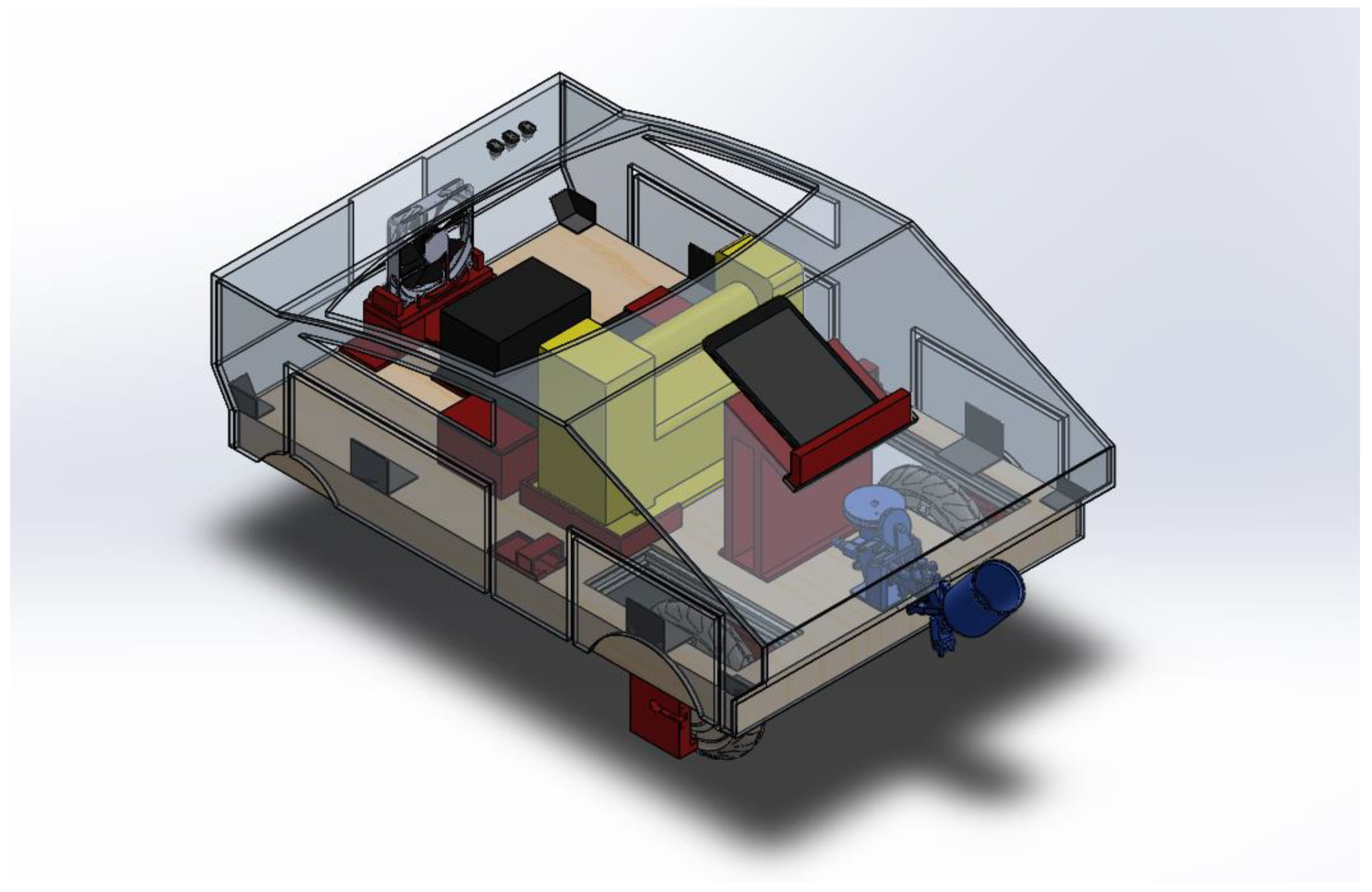
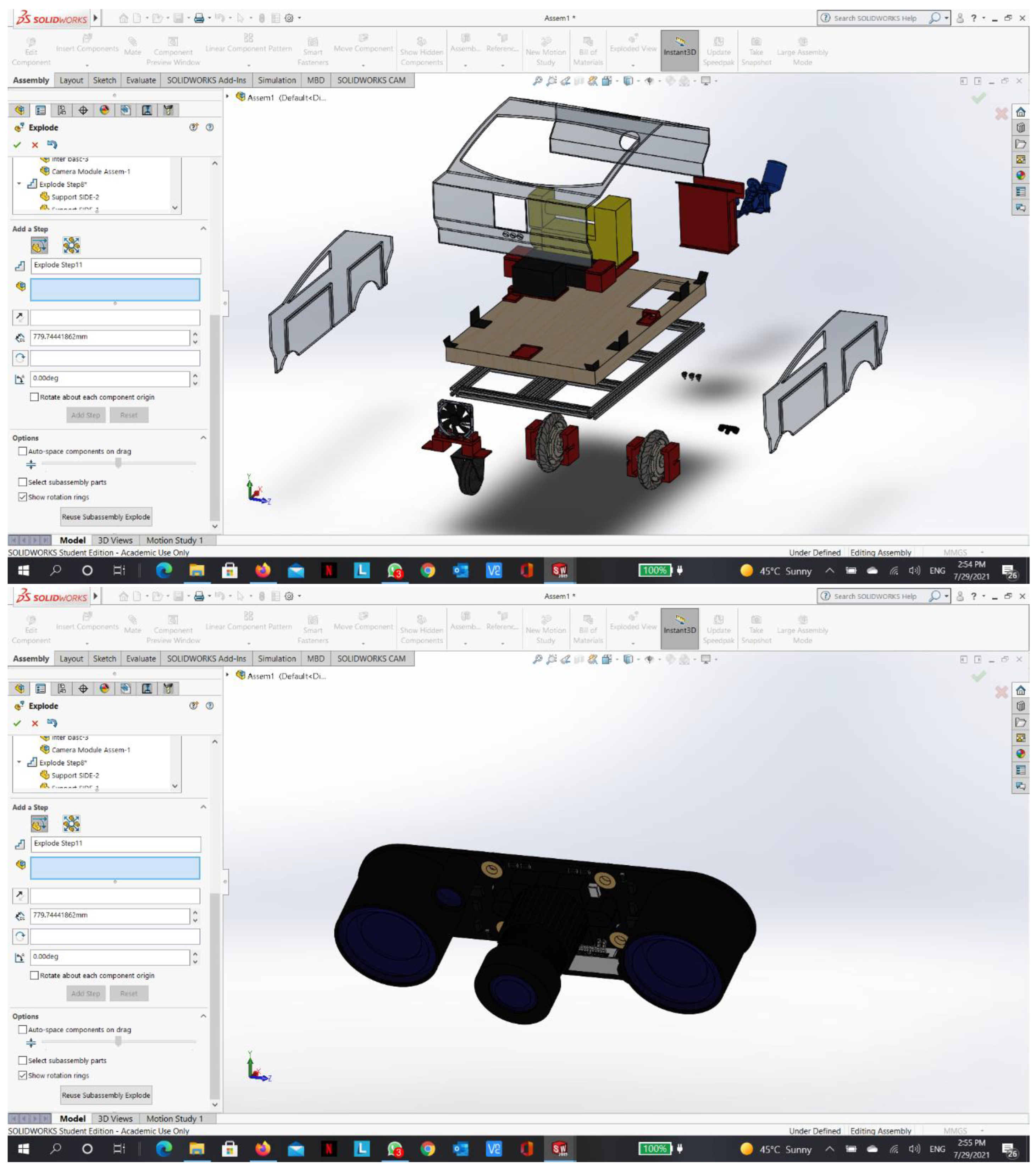
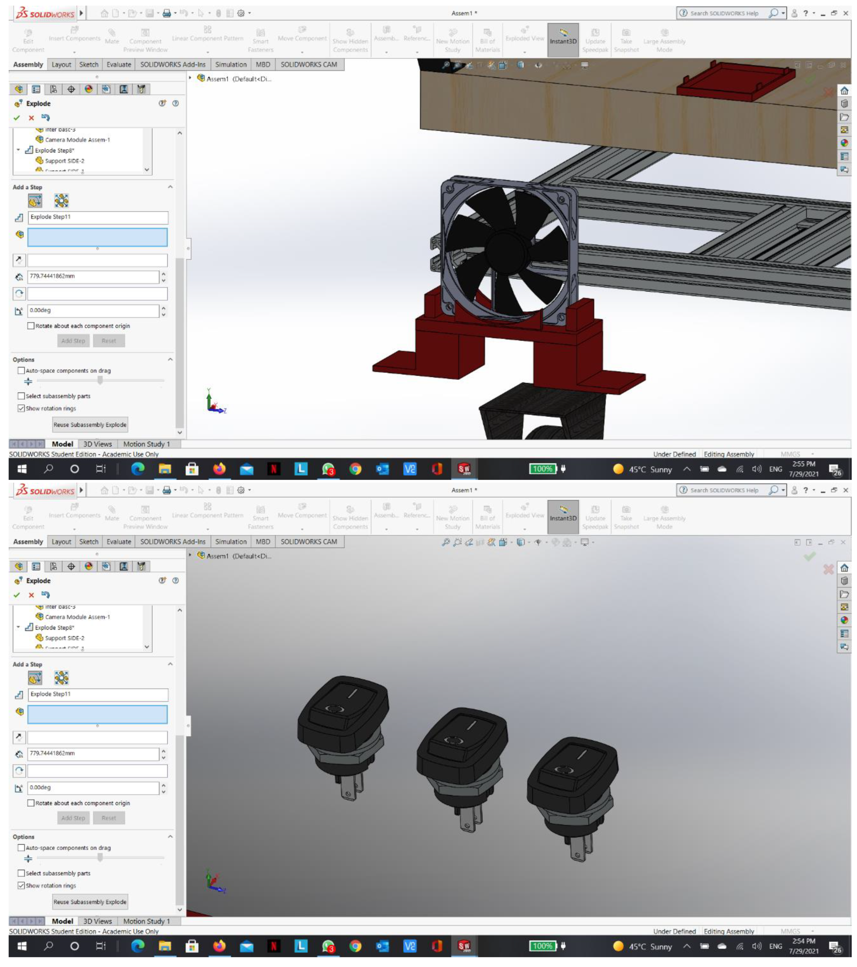
Figure 5.
Front exploded view.
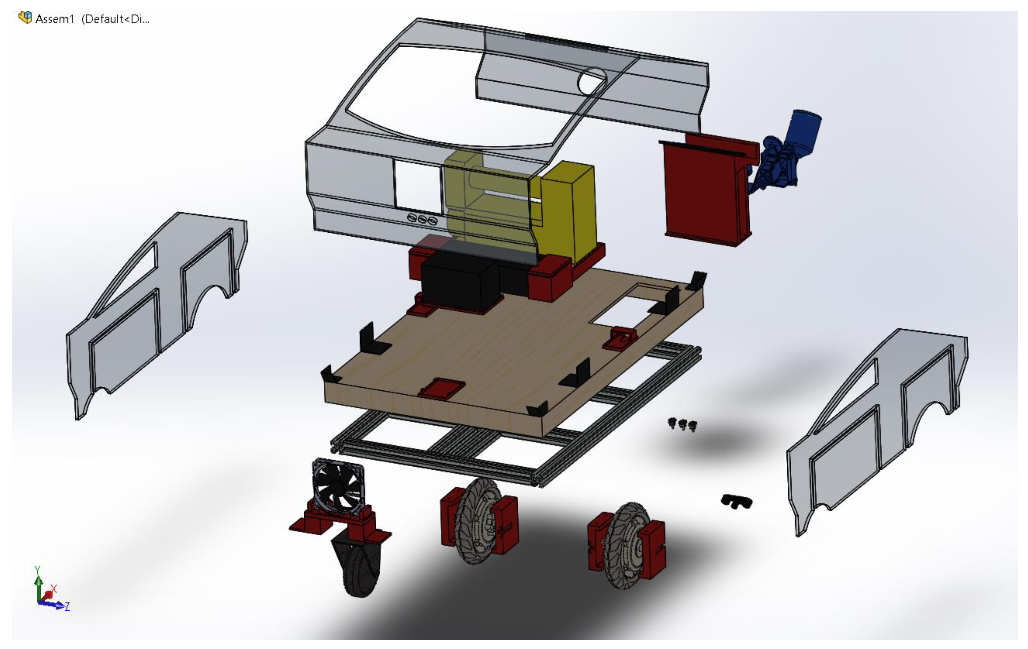
Figure 6.
Rear exploded view.
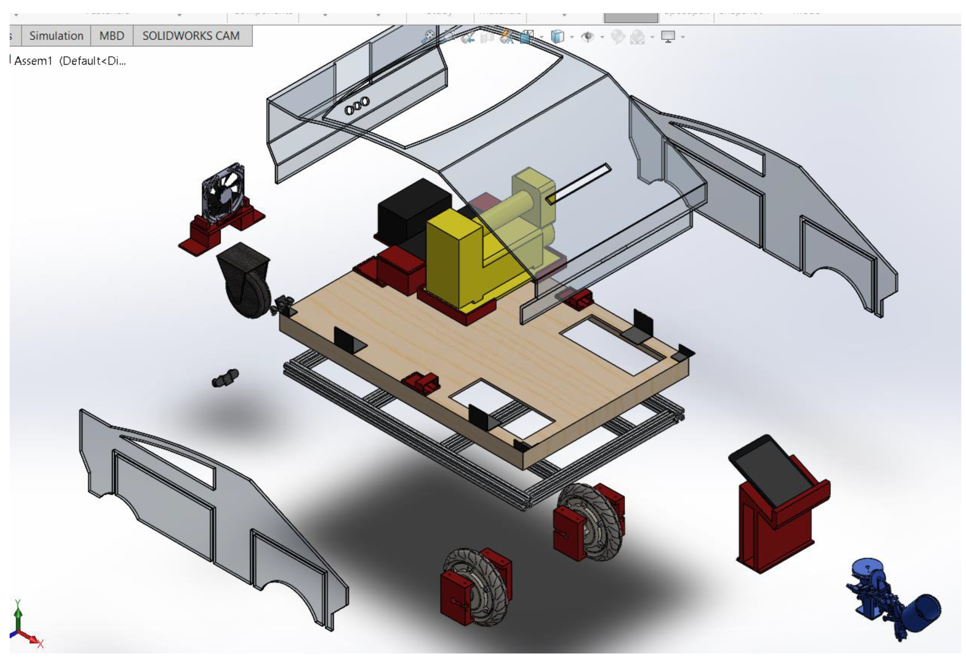
Figure 7.
Drawing.
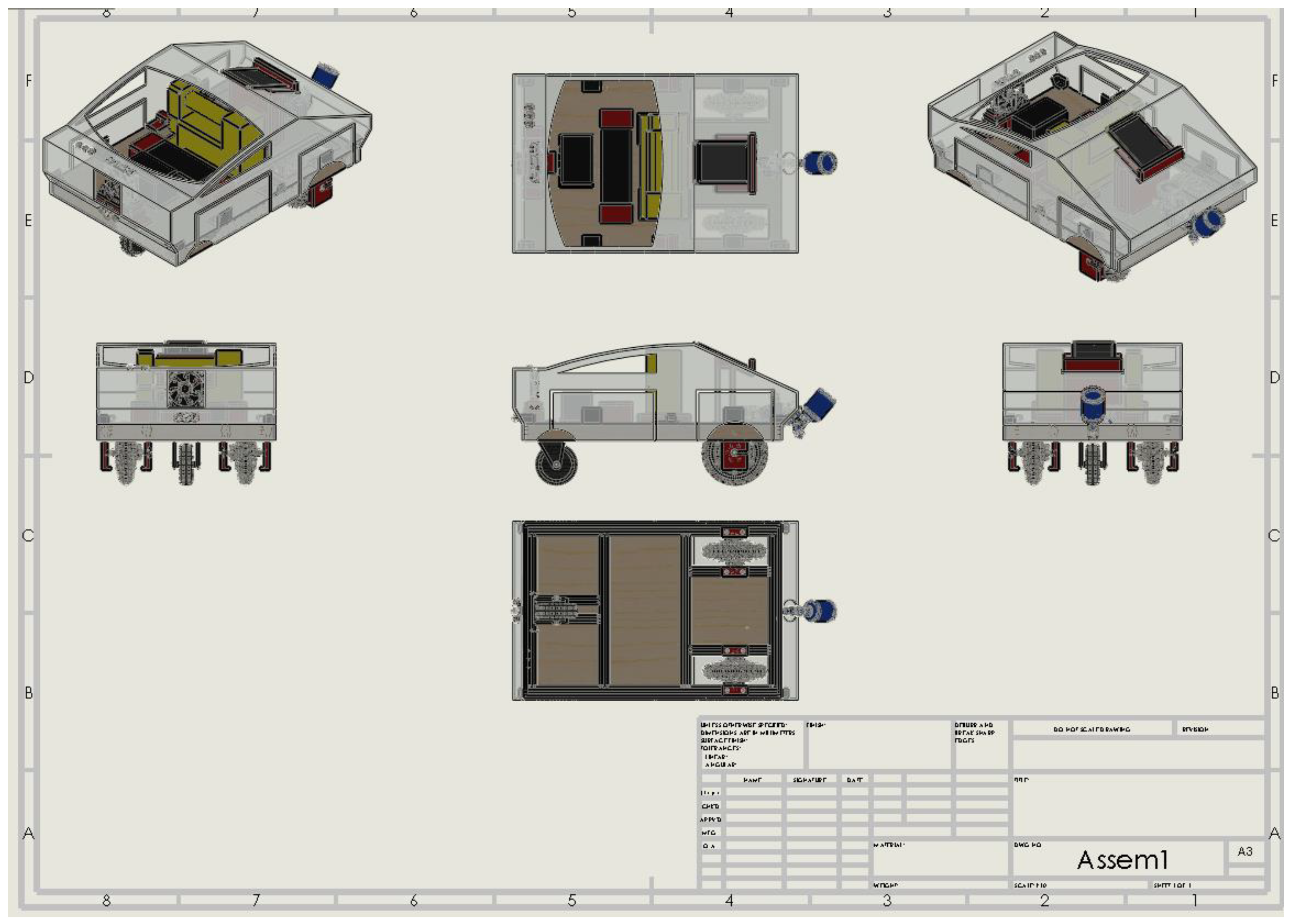
Figure 8.
Assembly dimensions (mm).
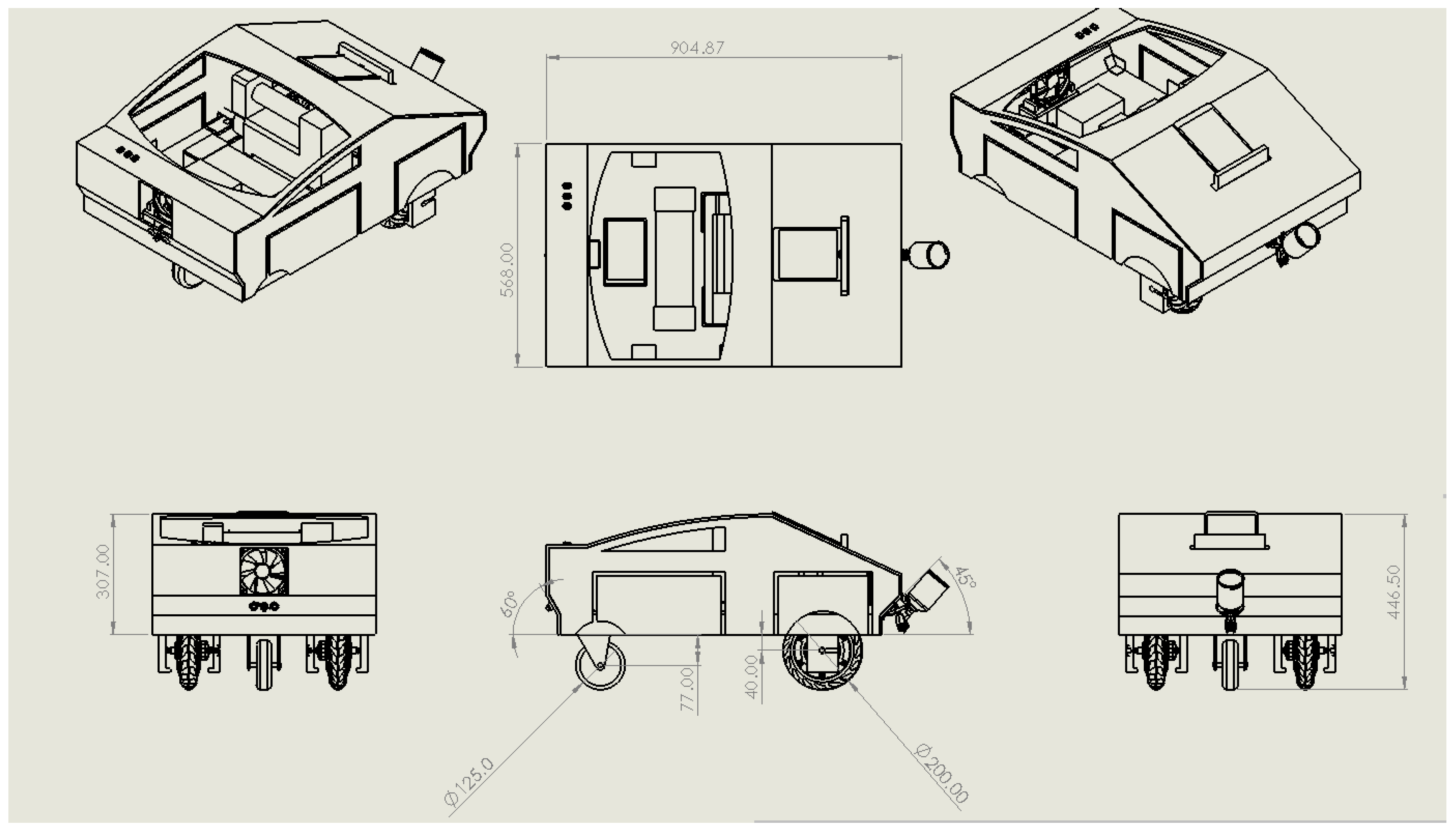
Figure 9.
Aluminum extrusion profile 30x30 light.
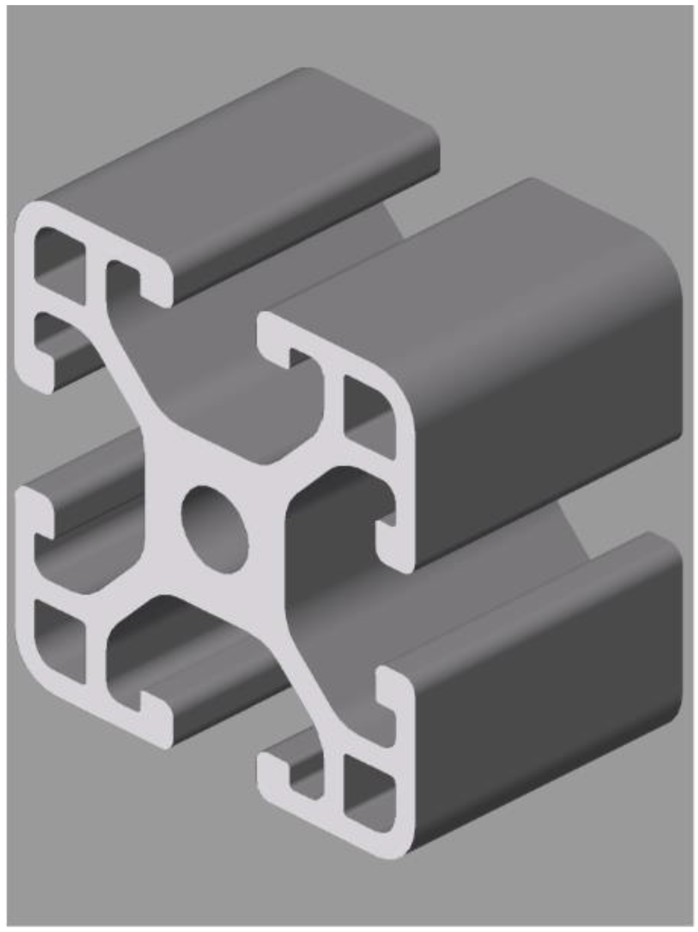
Figure 10.
Assembled frame.
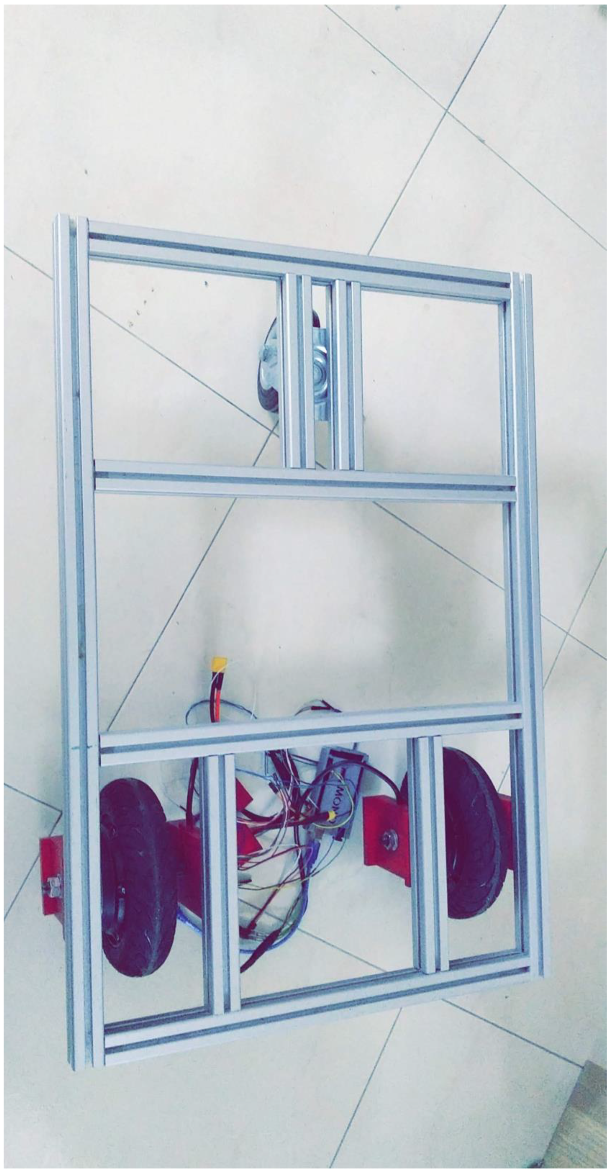
Figure 11.
Cardboard cover.
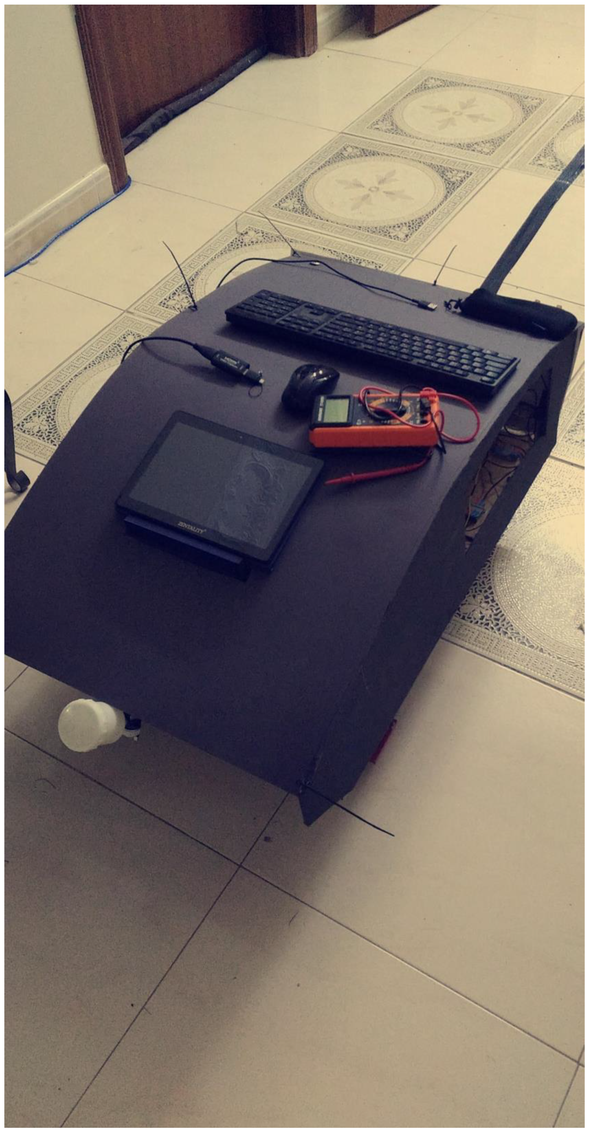
Figure 14.
Sprayer control knobs.
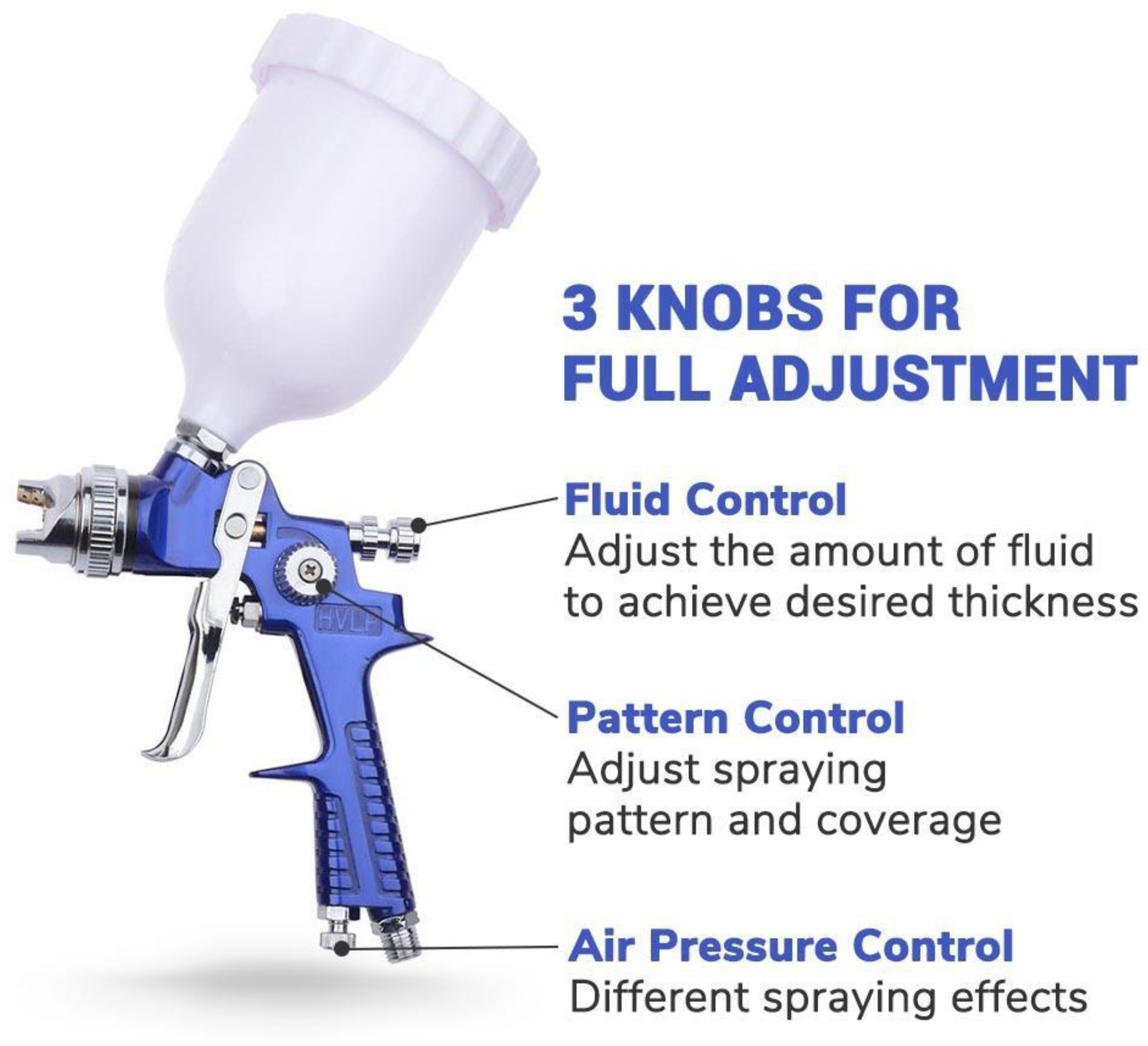
Figure 15.
Pulley system.
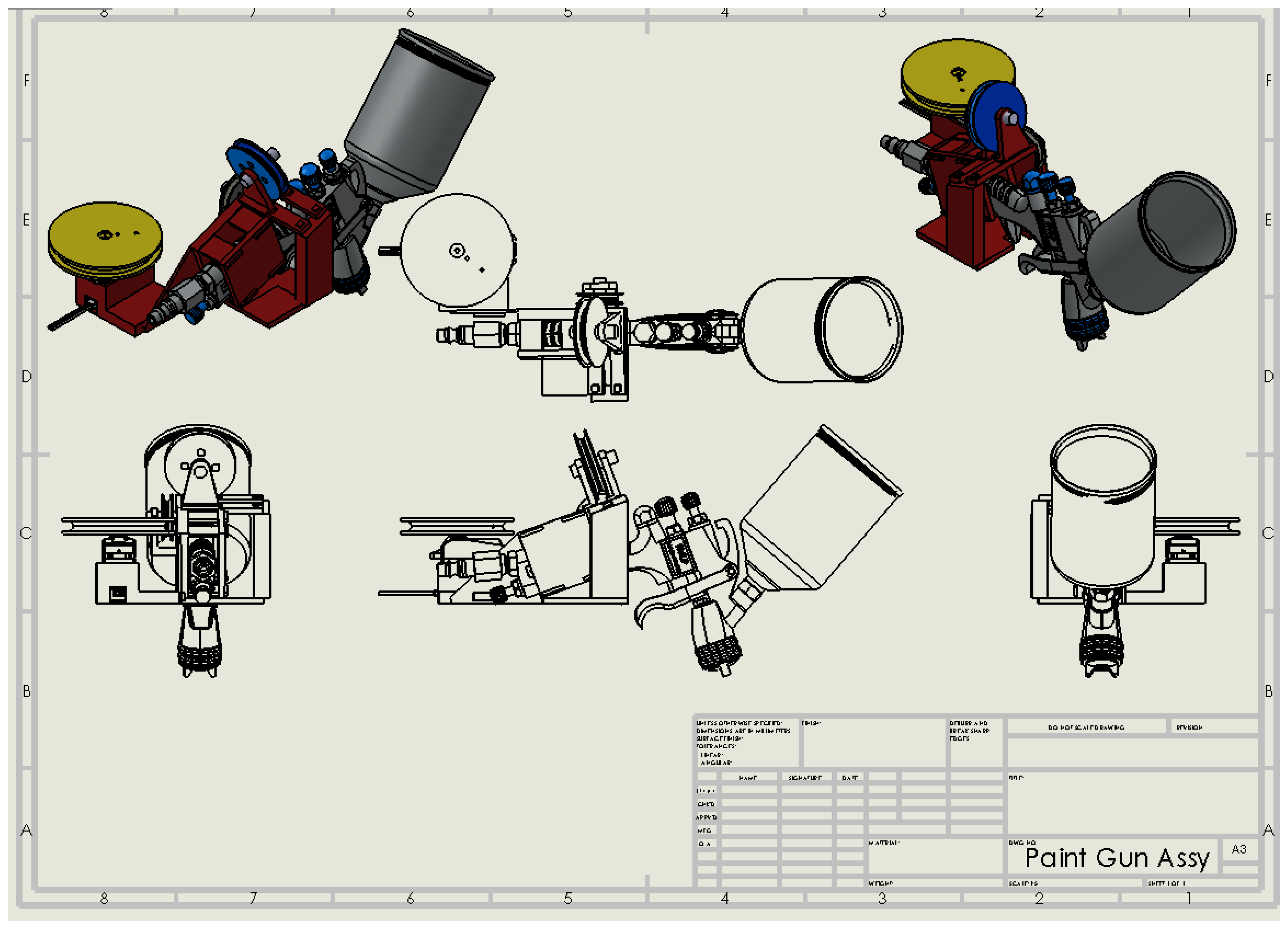
Figure 16.
Motorized wheel.
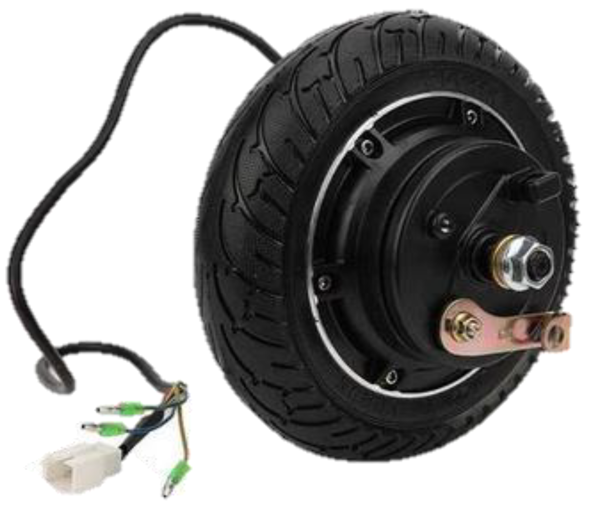
Figure 17.
Castor wheel.
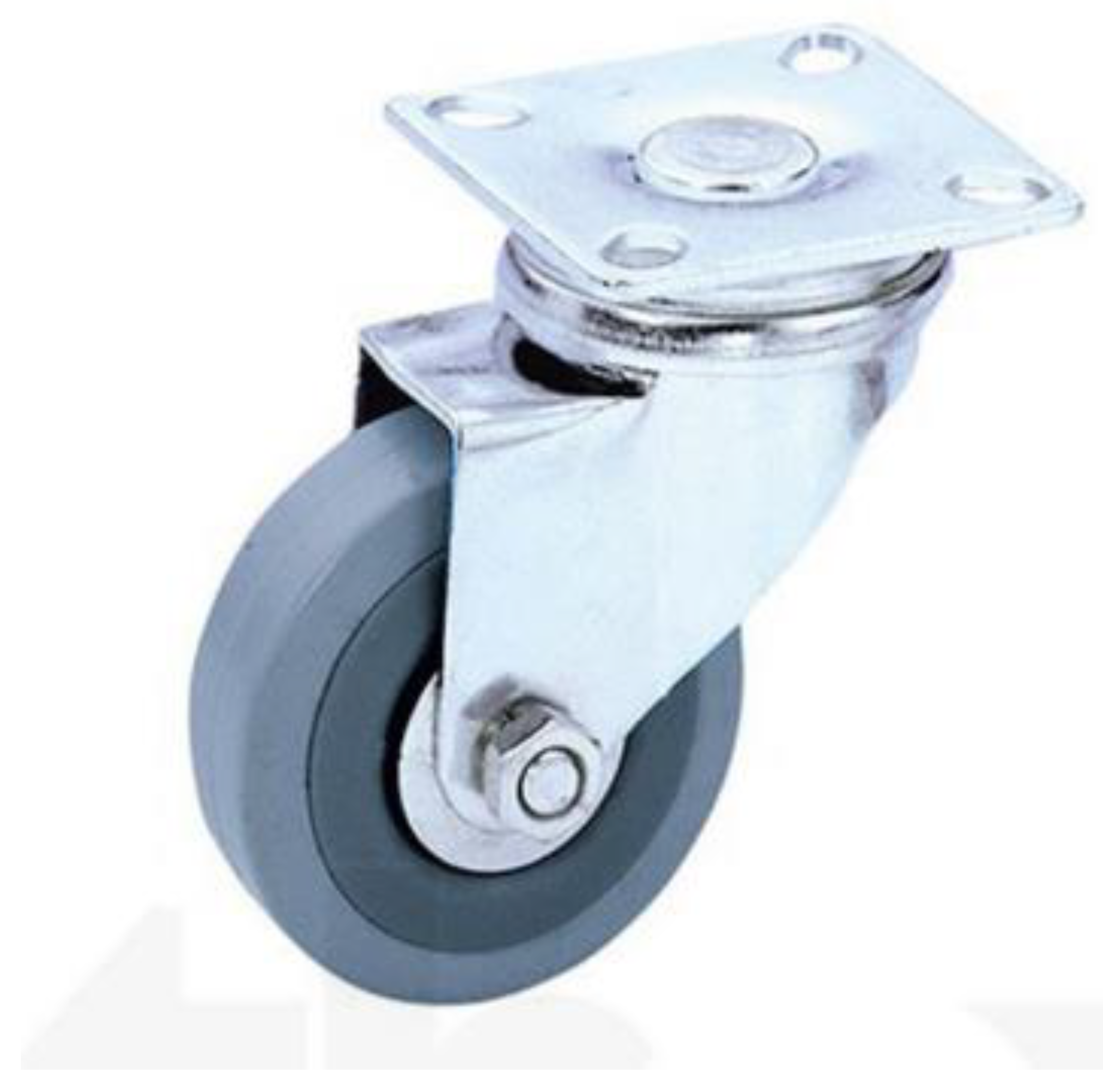
Figure 18.
Power Connection.
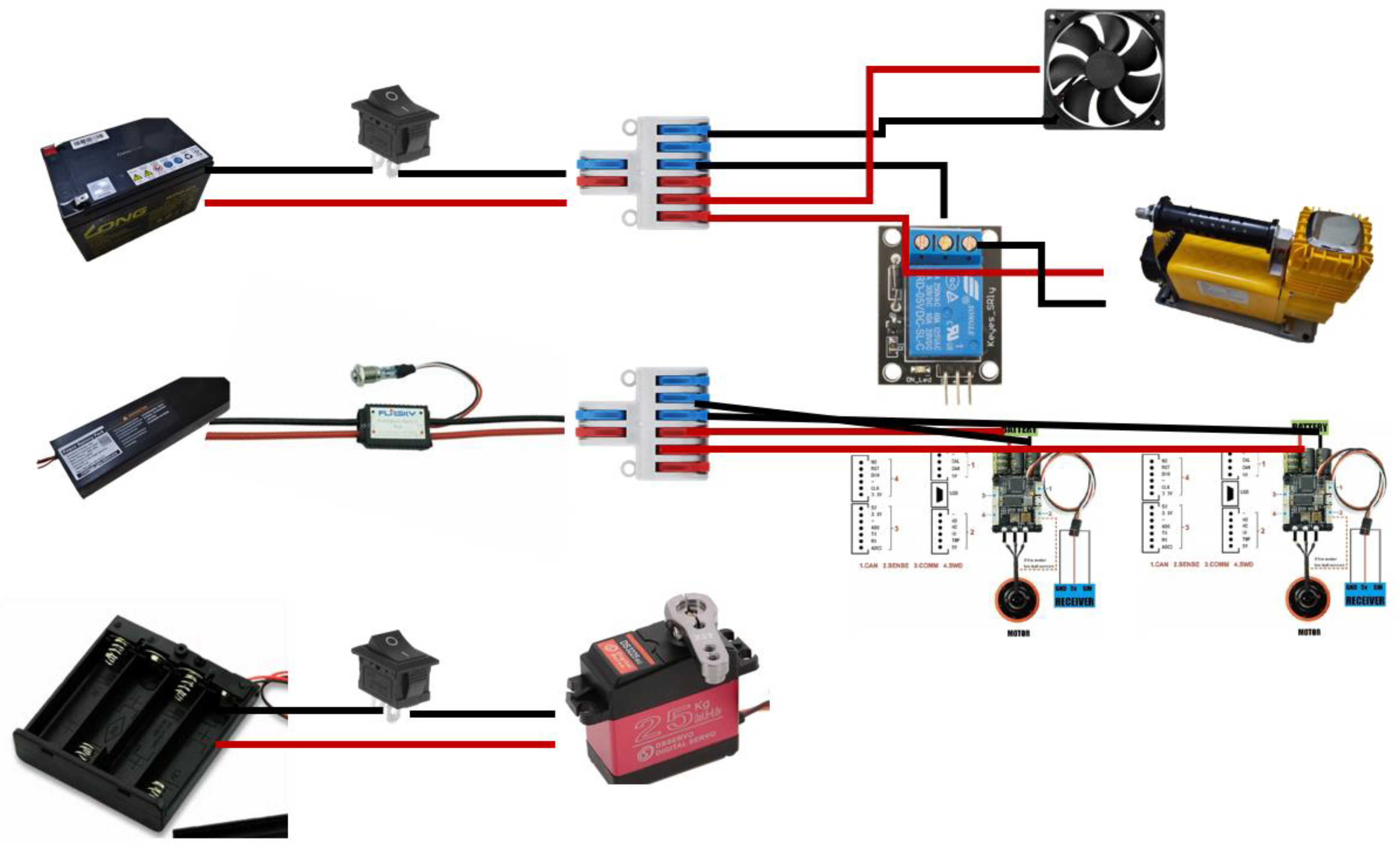
Figure 19.
Signaling Connection.
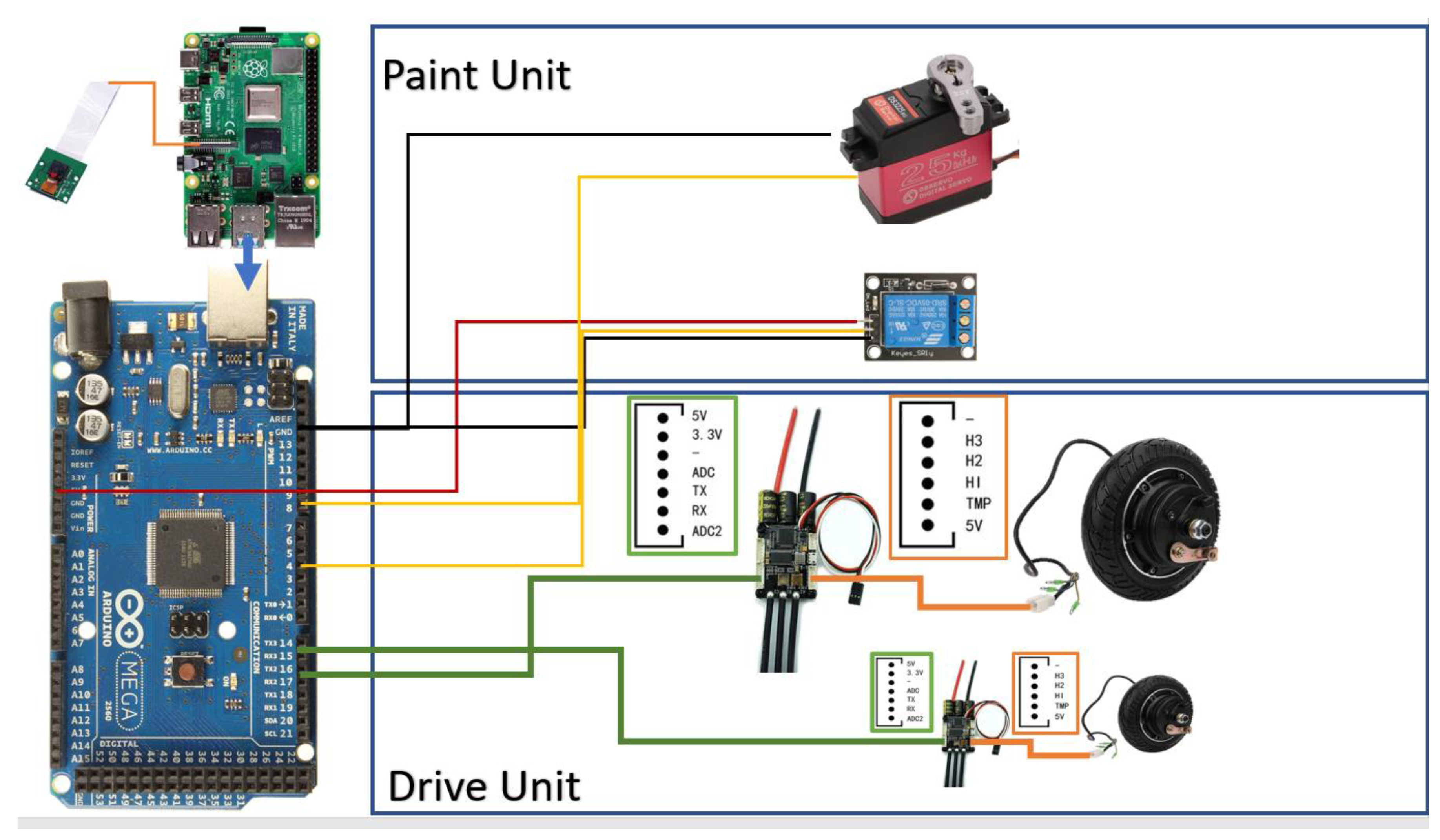
Figure 20.
Control Architecture.
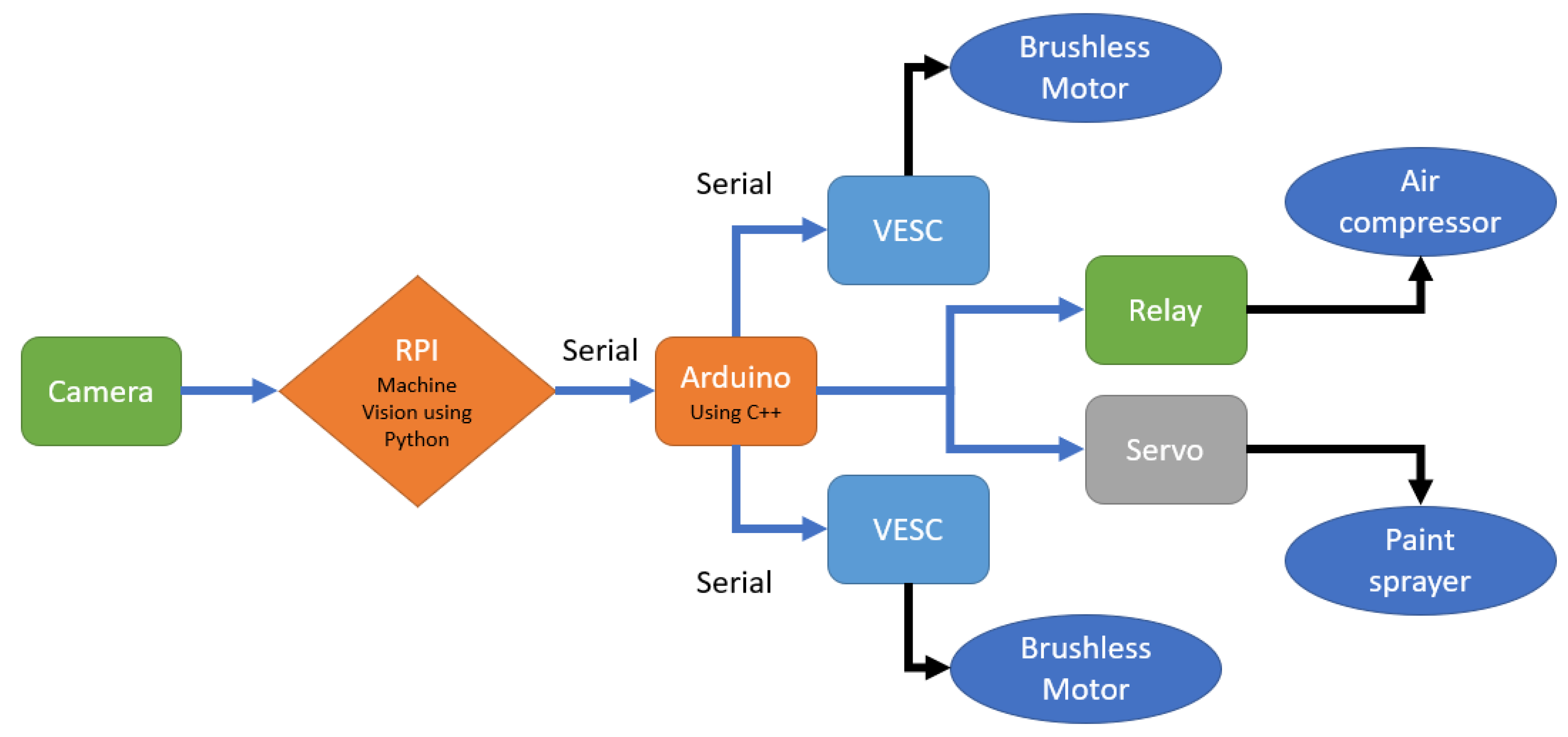
Figure 21.
SSH, VNC enabling.
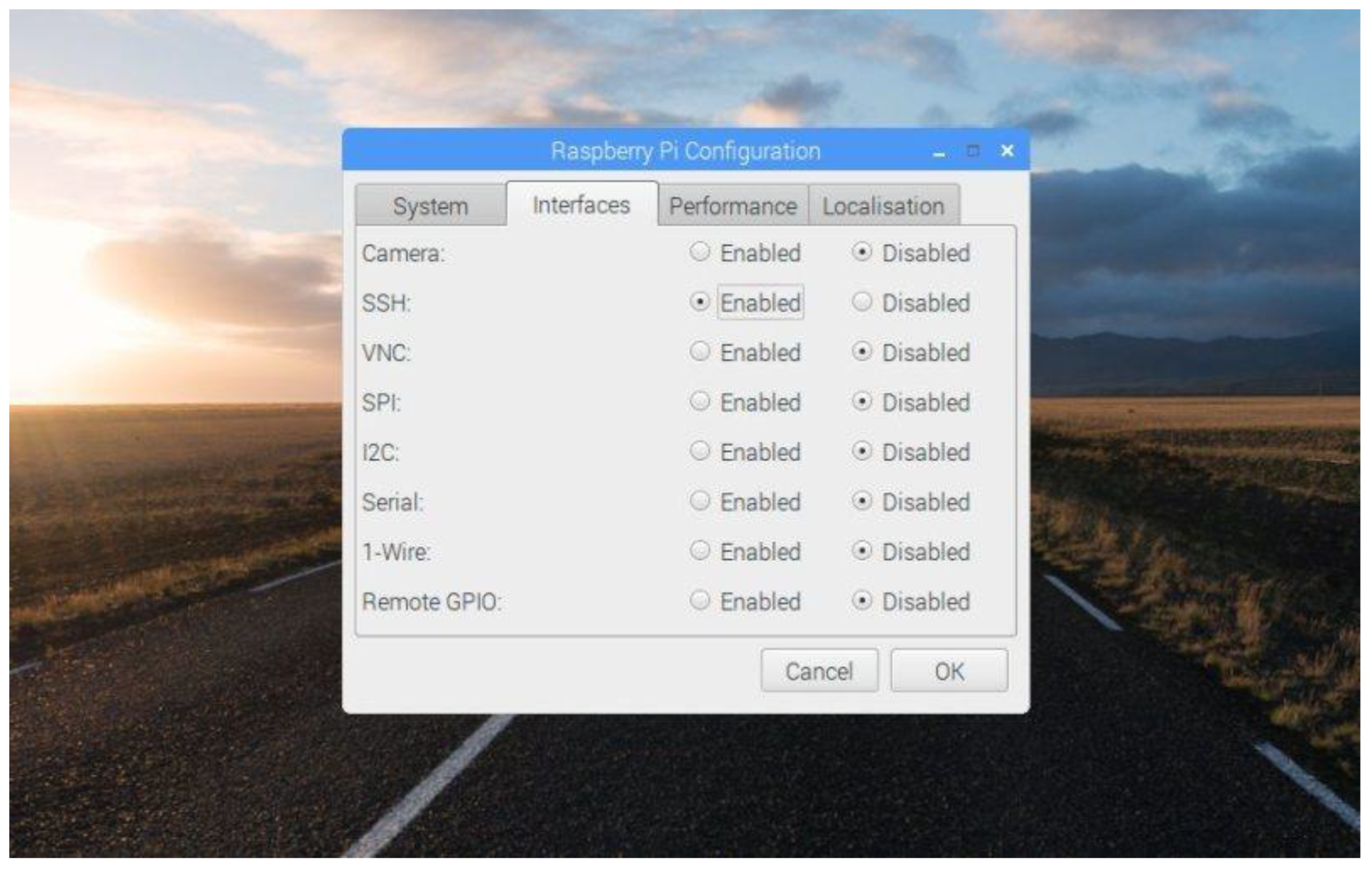
Figure 22.
SSH Connection.
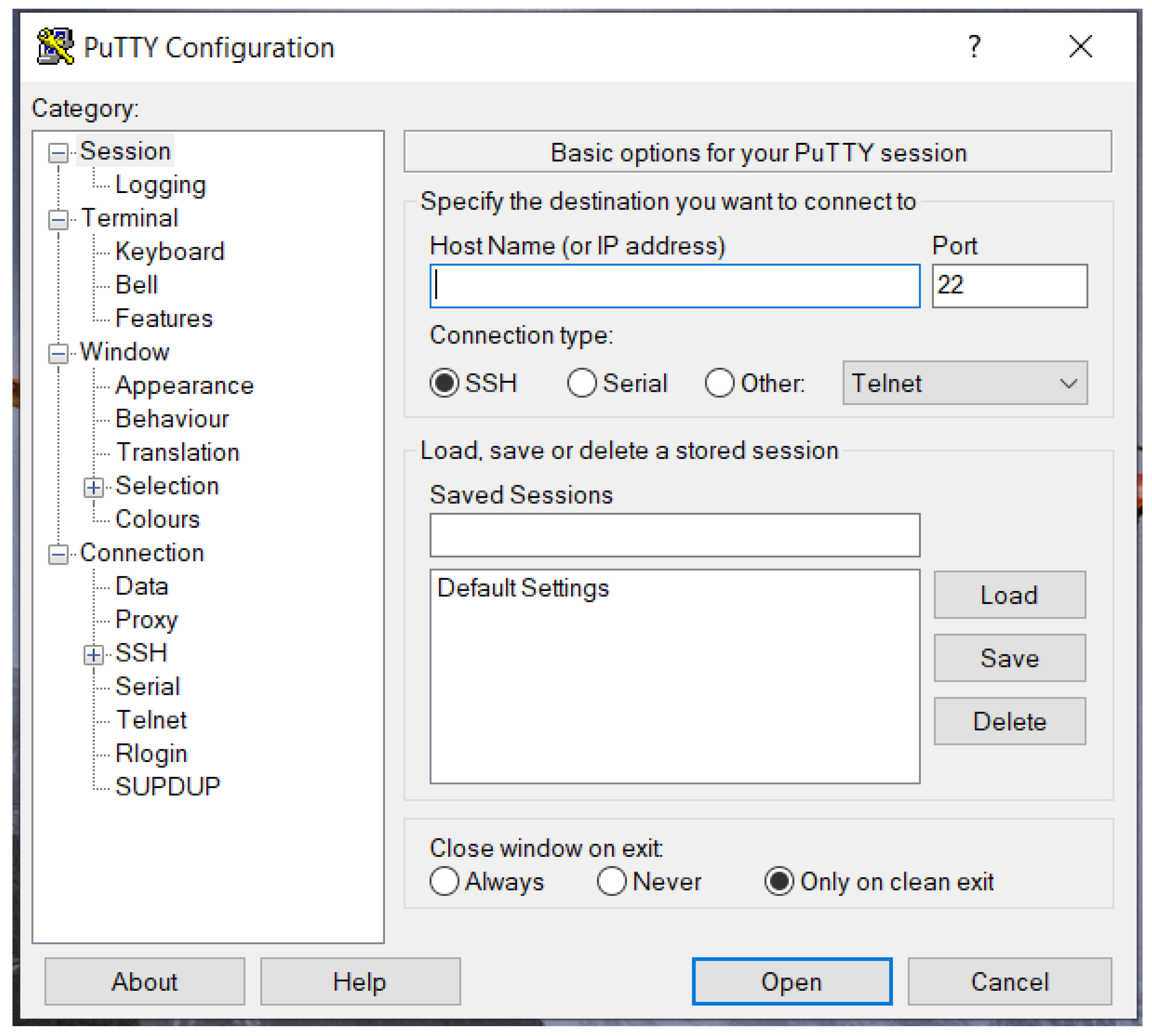
Figure 23.
VNC virtual desktop.
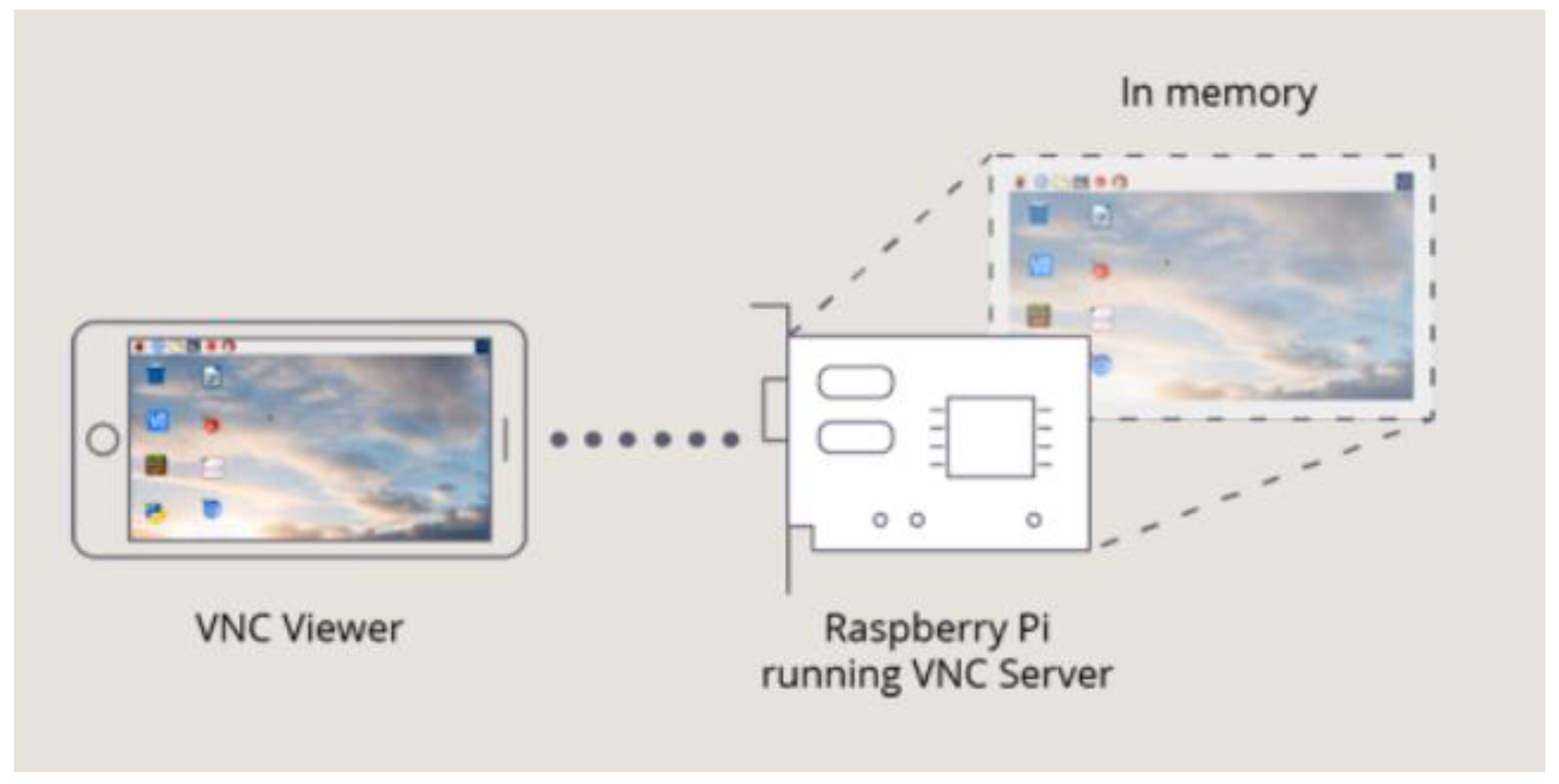
Figure 24.
RPI camera.
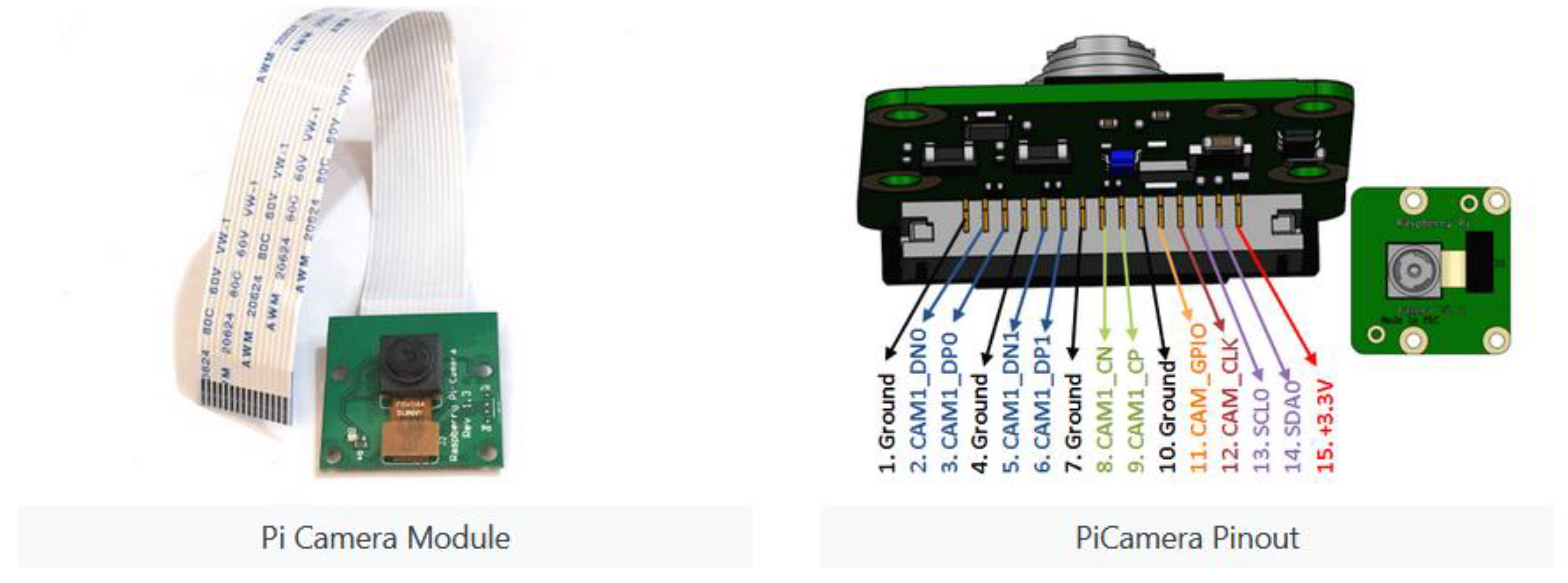
Figure 26.
Differential Drive illustration.
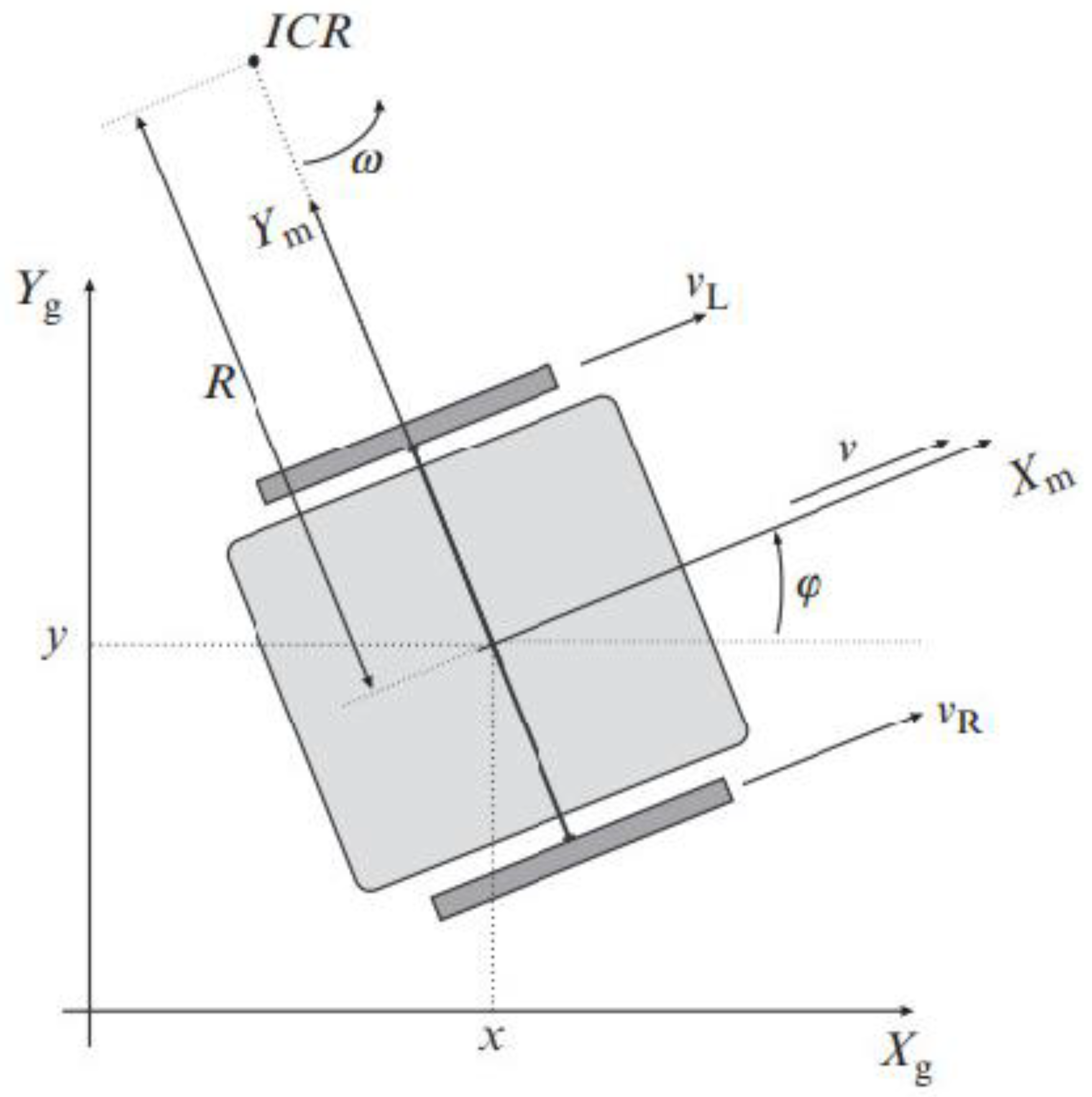
Figure 27.
Control to Reference Pose.
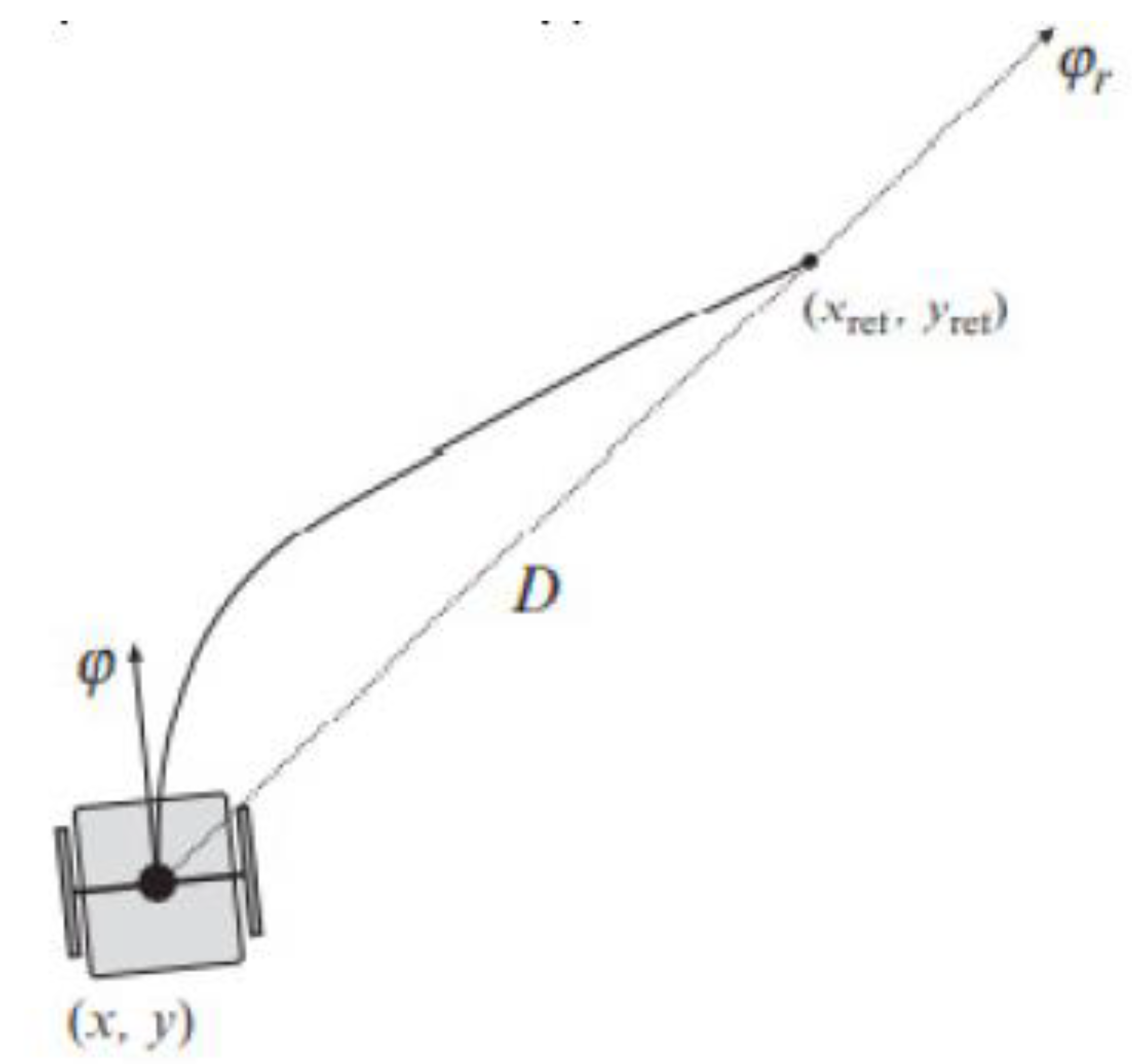
Figure 28.
Differential Drive kinematics.
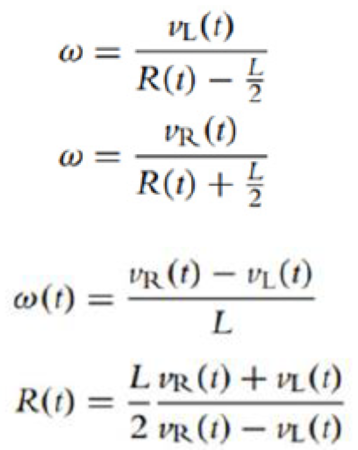
Figure 30.
Initial connectors.
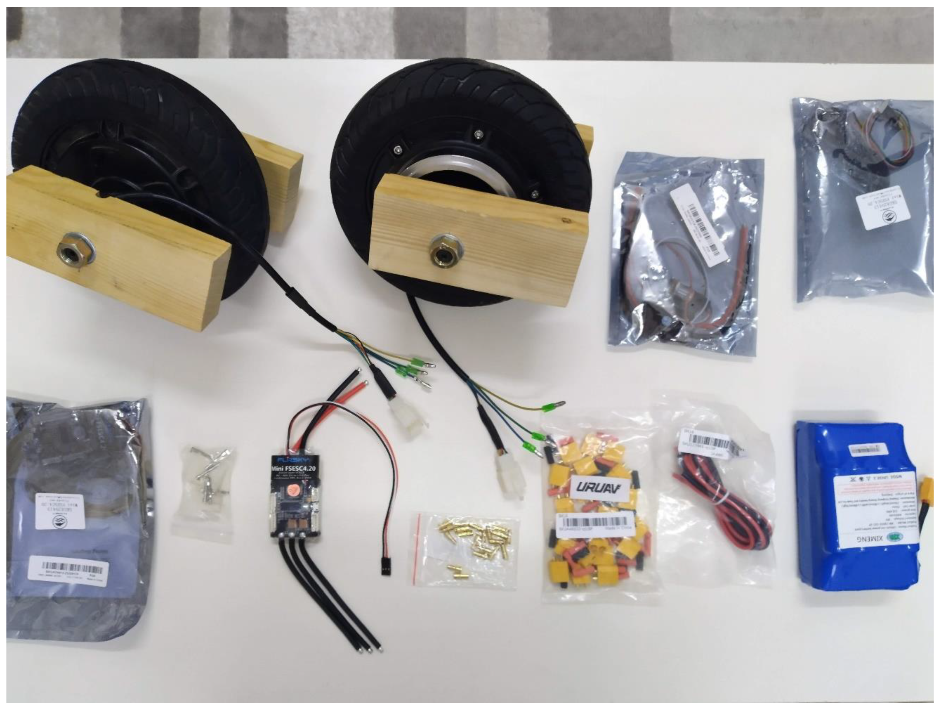
Figure 31.
Final connection.
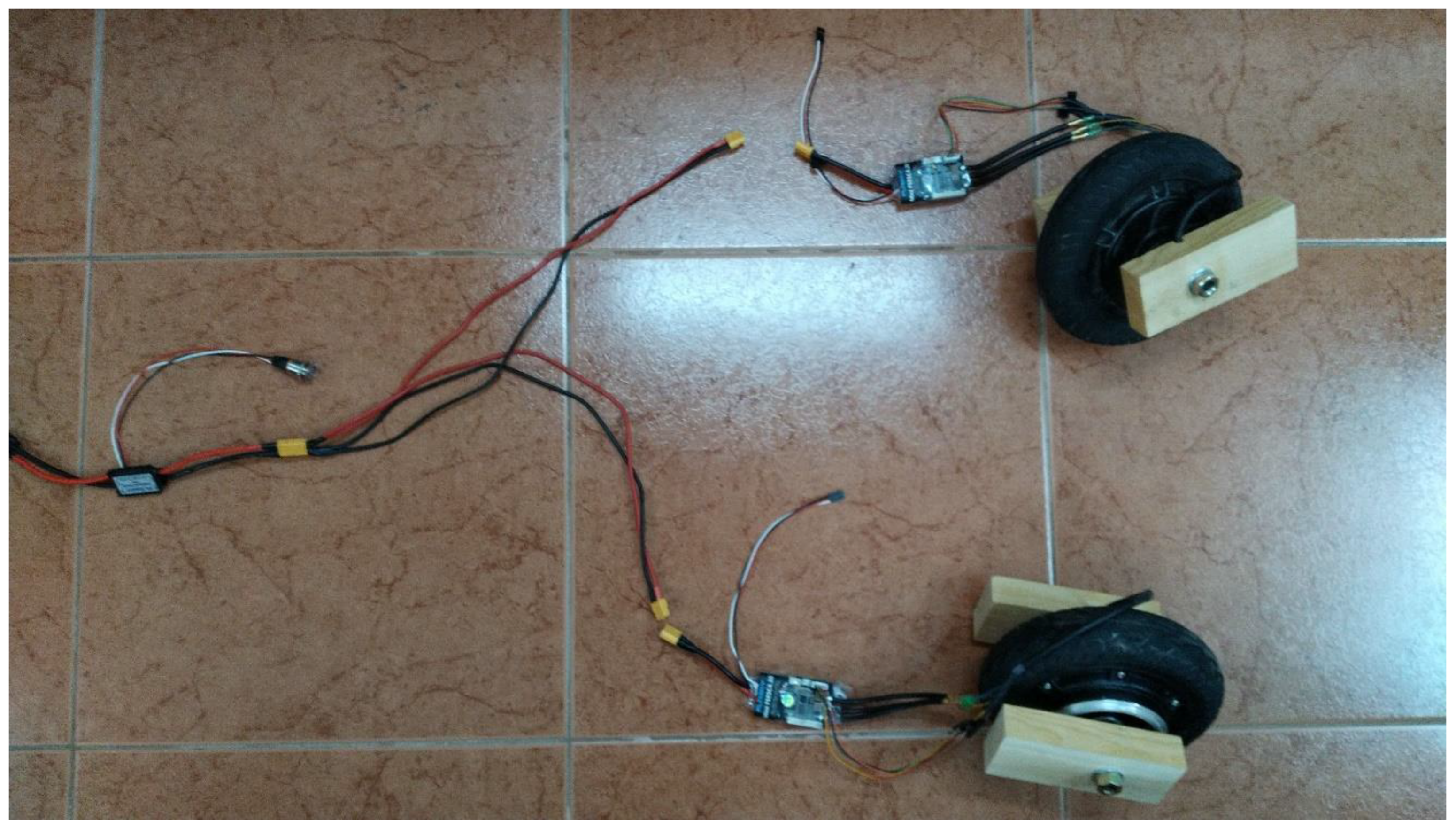
Figure 35.
WAGO Two Groups of Parallel One-in Three-out Splitter.
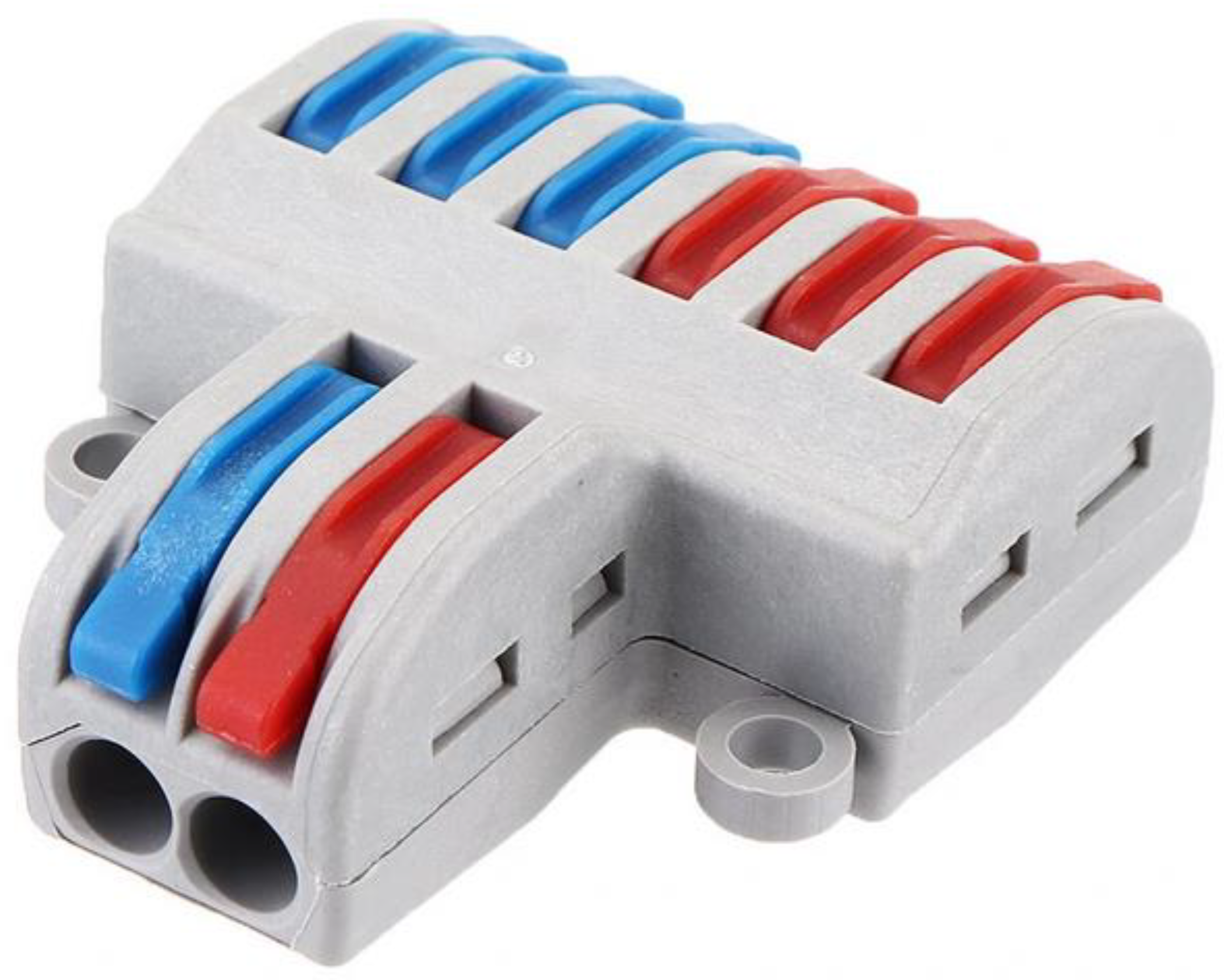
Figure 36.
Actual connection.
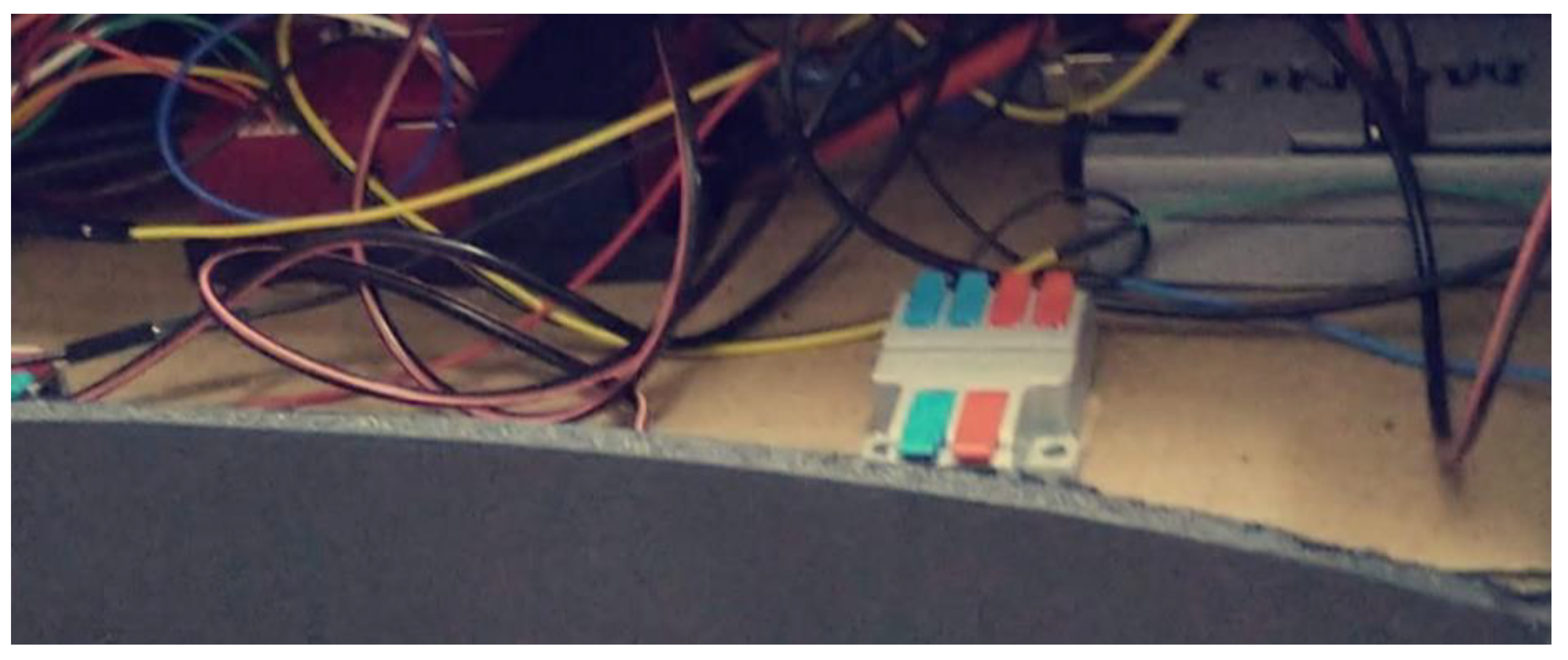
Figure 41.
HSV spectrum.
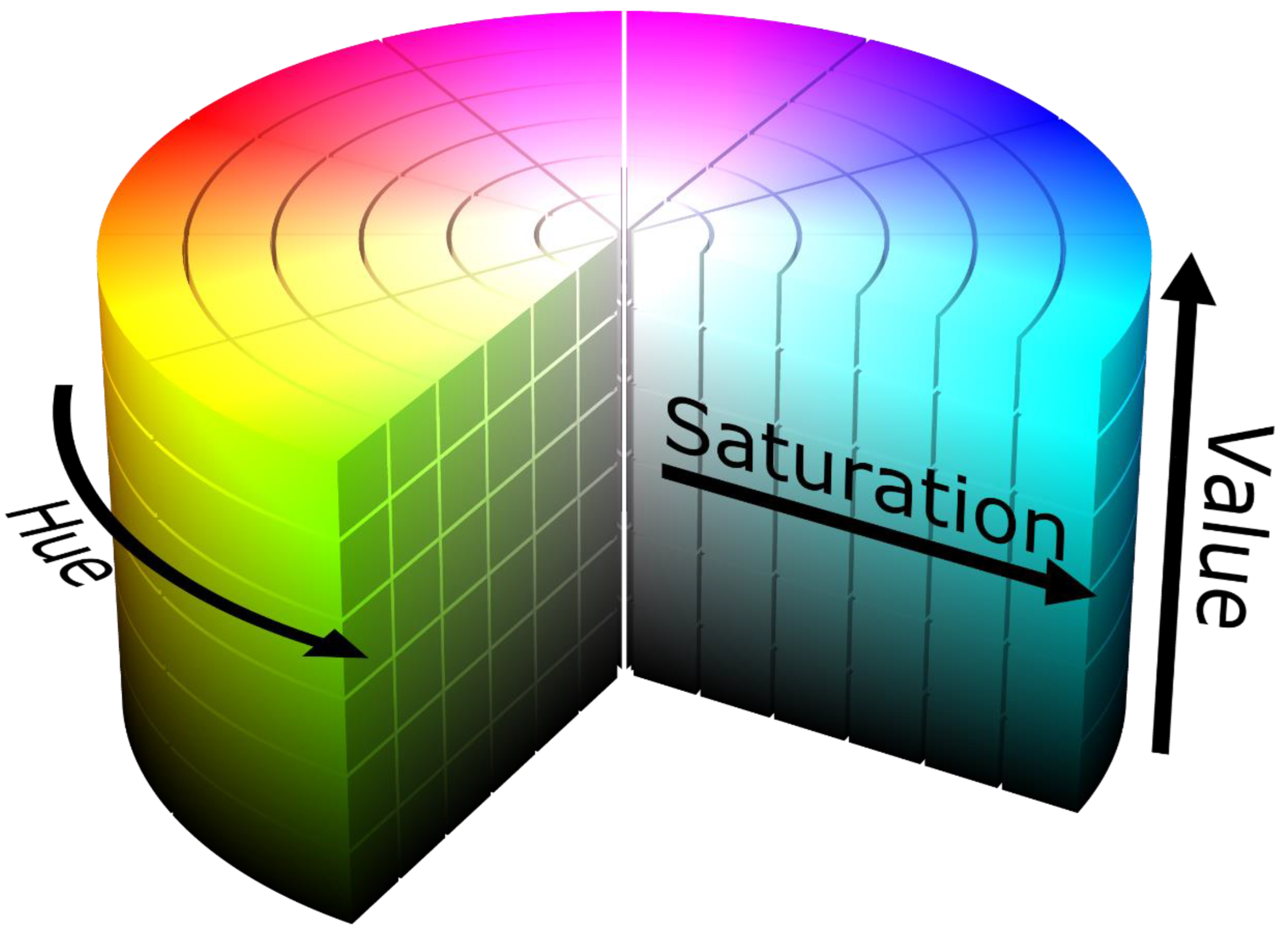
Figure 42.
Purple Color detection test.
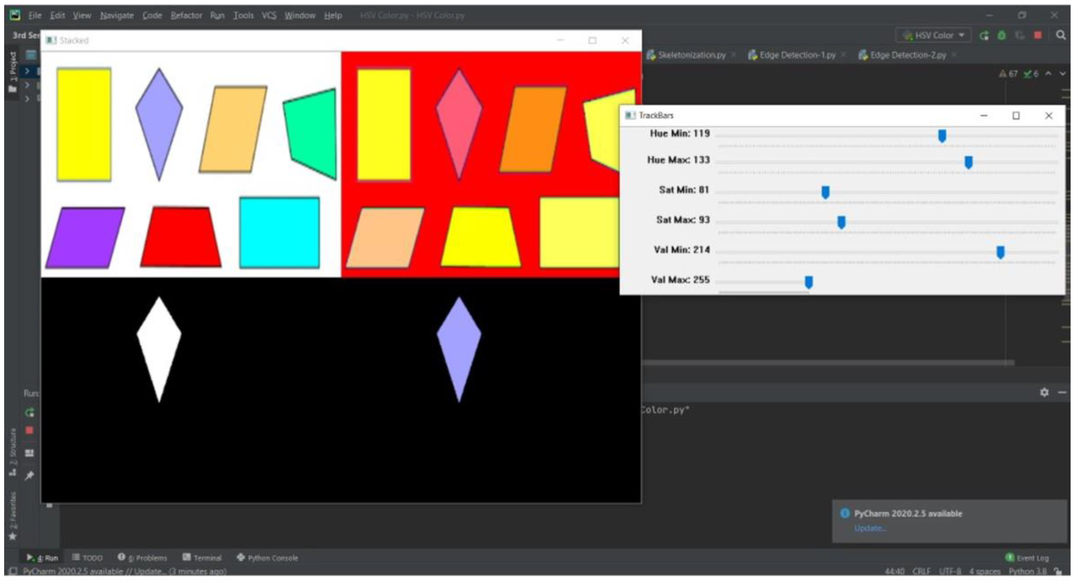
Figure 43.
Contour Detection test.
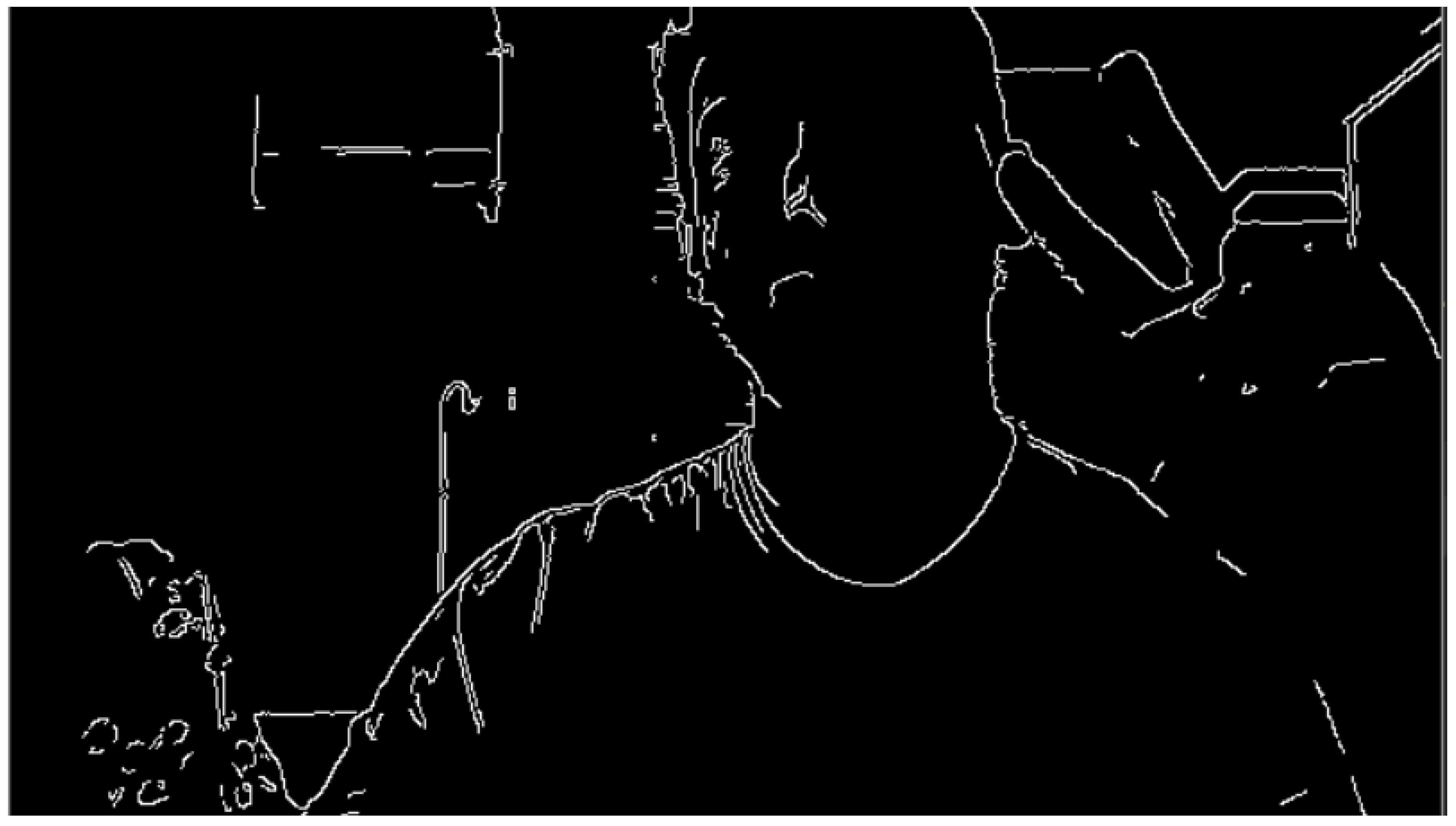
Figure 44.
Boundary points locations test.
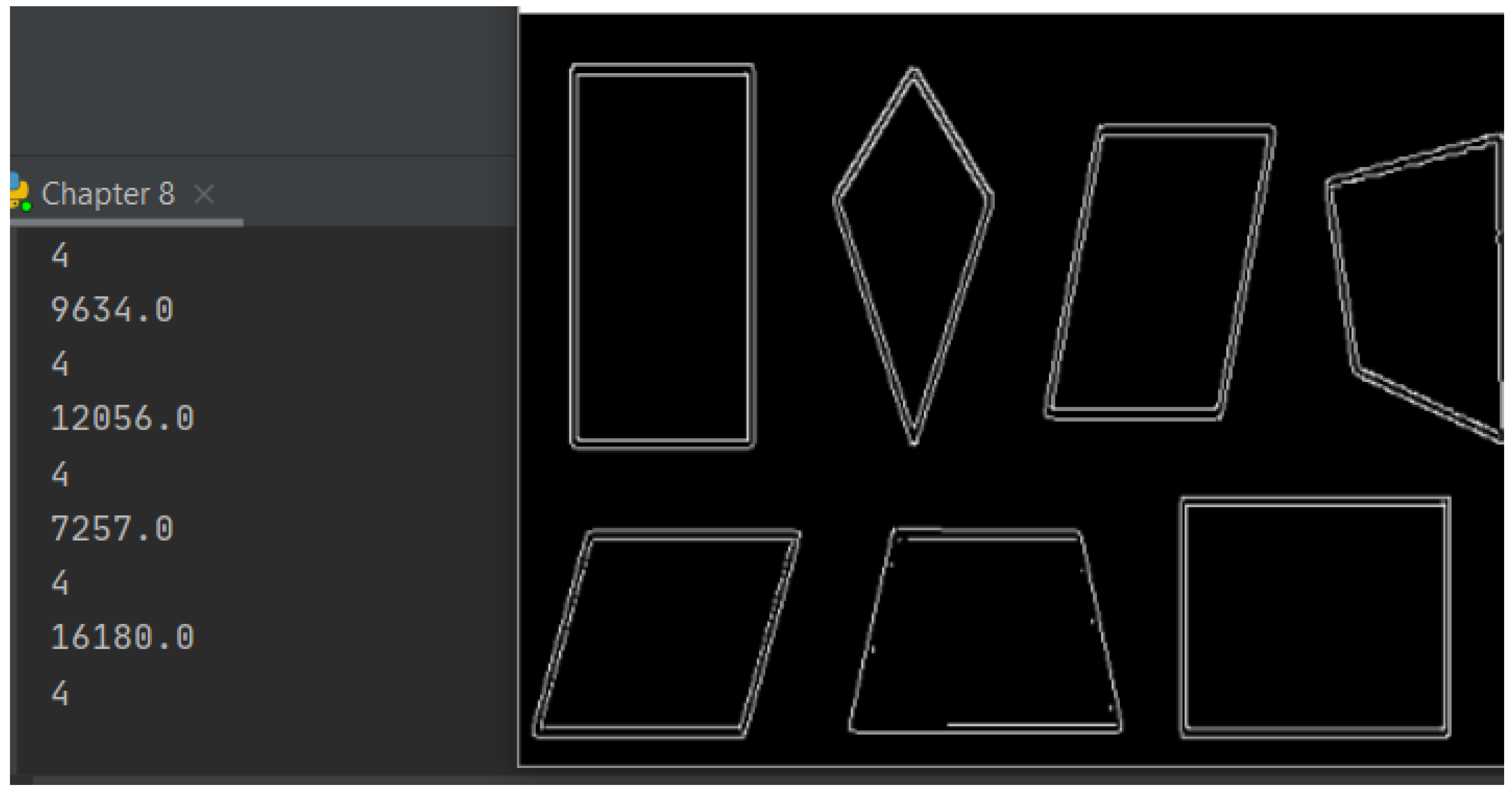
Figure 45.
Shape recognition test.
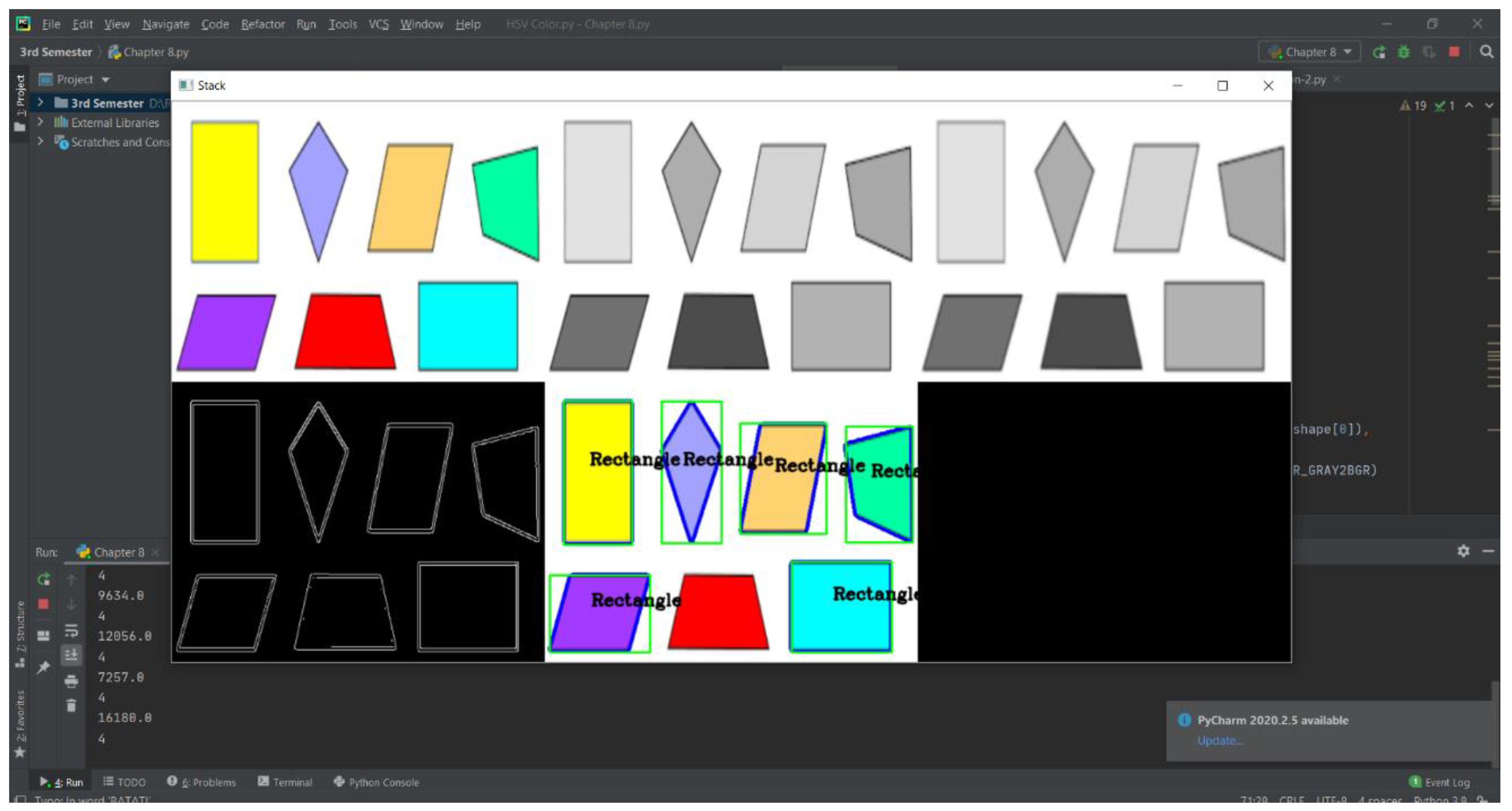
Figure 46.
Color Mean and Standard deviation of the detected shape inside a contour.
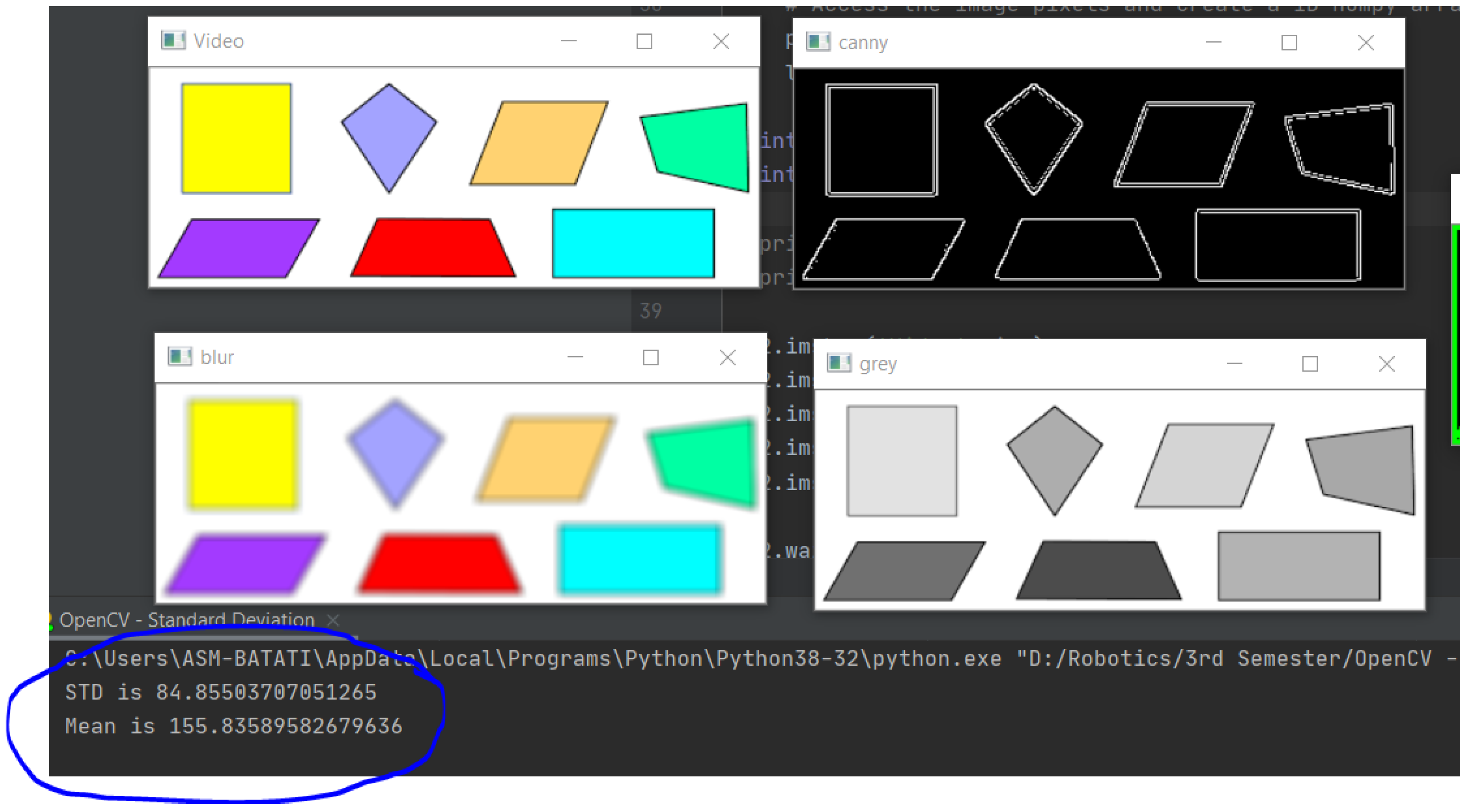
Figure 47.
Error and Angle detection test.
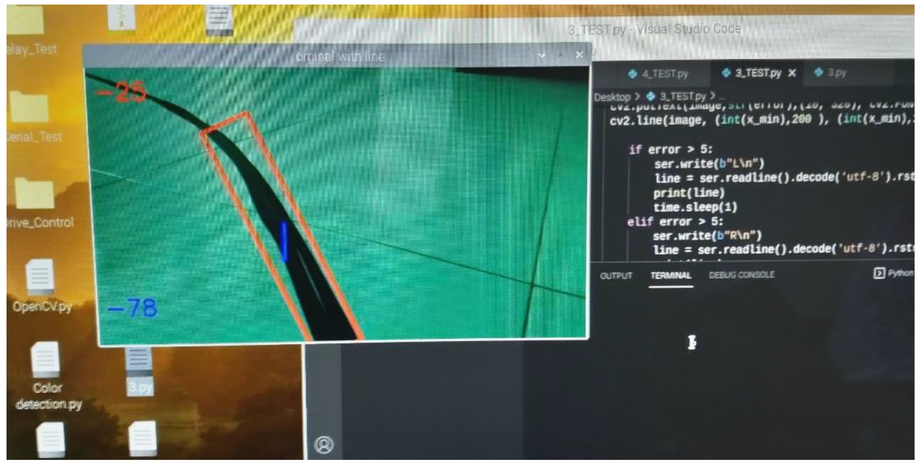
Figure 48.
Wheels mounts modification.
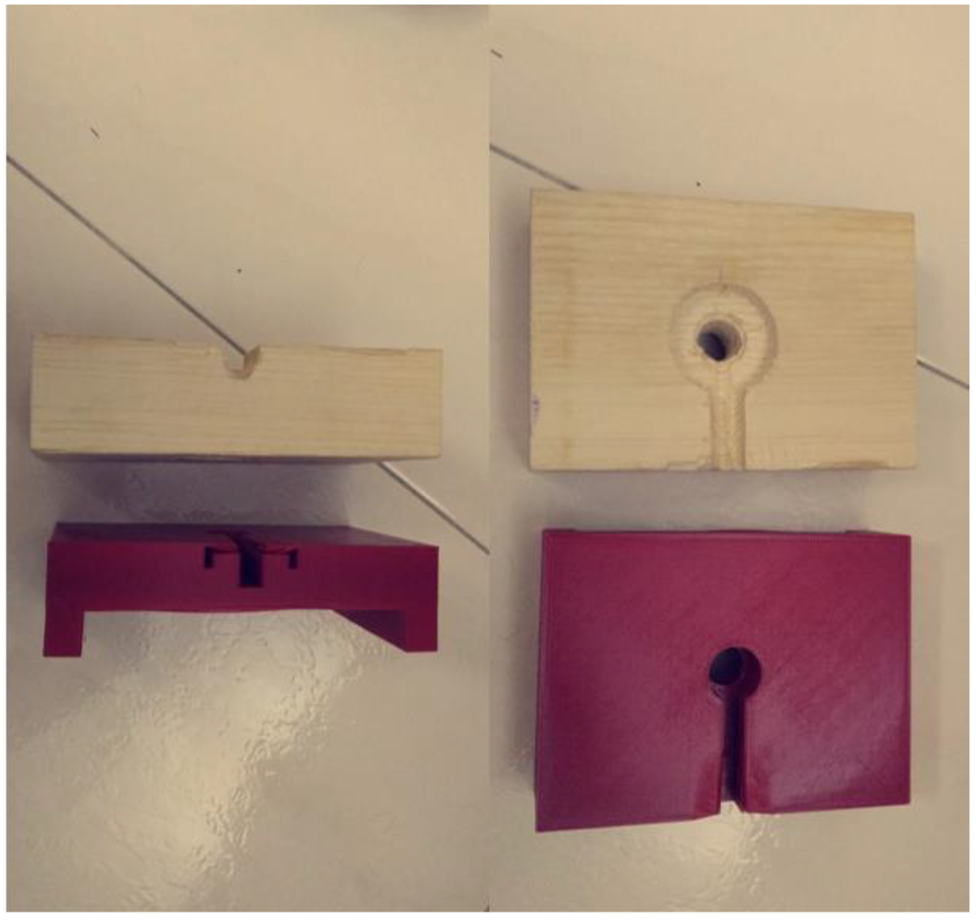
Table 3.
Hardware components.
| Chassis |
|
| Drive Unit |
|
| Paint Unit |
|
| Sensors |
|
| Control Unit |
|
| Power |
|
| Performance & UI. |
|
Table 4.
Frame Pugh’s chart.
| Availability in JED | Assembling difficulty | Quality | Price | Total | |
| Aluminum Extruded Profile | +2 | +2 | +2 | -1 | +5 |
| Carbon Fiber Tubes | -2 | -1 | +2 | -2 | -3 |
| Sheet Metal Fabrication | +2 | -2 | -1 | +2 | +1 |
Table 5.
Painting method selection.
| Availability in JED | Energy consumption | Weight | Price | Total | |
| Air compressor + Paint gun | +2 | +2 | +2 | +1 | +7 |
| Paint pump | -2 | -2 | -2 | -2 | -8 |
| Airless paint gun | -2 | -2 | -2 | -2 | -8 |
Table 6.
Steering mechanism selection.
| . | Assembling difficulty | Control difficulty | Maneuverability | Price | Total |
| Steerable front wheels and motorized rear wheels (Ackermann steering drive) | -1 | -2 | +2 | -1 | 0 |
| Front castor wheel and Motorized rear wheels (Differential drive) | +2 | +2 | +1 | +1 | +6 |
Table 7.
Motors Tests.
| Motor\Test | Using VESC tool | Using Arduino serial | Using Raspberry Pi serial to Arduino |
| Right | OK | OK | Failure ( Burnt the motor with the VESC ) |
| Left | OK | OK | OK |
| Right ( New ) | OK | OK | OK |
Table 8.
Sprayers Tests.
| Sprayer\Test | Water – No valve | Water – air valve | Paint – air valve |
| Siphon HVLP | OK | OK | Low paint volume |
| Gravity feed HVLP (small) | OK | OK | OK |
| Gravity feed HVLP (large) | OK | OK | Failure ( Valve exploded ) |
Disclaimer/Publisher’s Note: The statements, opinions and data contained in all publications are solely those of the individual author(s) and contributor(s) and not of MDPI and/or the editor(s). MDPI and/or the editor(s) disclaim responsibility for any injury to people or property resulting from any ideas, methods, instructions or products referred to in the content. |
© 2024 by the authors. Licensee MDPI, Basel, Switzerland. This article is an open access article distributed under the terms and conditions of the Creative Commons Attribution (CC BY) license (http://creativecommons.org/licenses/by/4.0/).
Copyright: This open access article is published under a Creative Commons CC BY 4.0 license, which permit the free download, distribution, and reuse, provided that the author and preprint are cited in any reuse.


