1. Introduction
Optimal control theory provides a powerful framework for determining a dynamic system’s control law that extremizes an objective function [
1]. It has been applied in many fields, including engineering, economics, and biology, to name a few. This study focuses on its application to energy maximization for a general class of second-order, nonlinear, time-varying dynamic systems.
A common yet challenging class of optimal control problems are the Linear Optimal Problems (LOPs), also known as singular problems. They occur when the inputs appear linearly in the system’s state equation and cost function, even though the state equations may be nonlinear in the states. This means that the control law cannot be formed directly by applying the stationary condition of optimality [
2]. Several researchers have investigated the existence and solution of singular problems in optimal control [
3,
4,
5,
6,
7]. Scardina [
8] investigated the necessary conditions for optimality for singular problems using Pontryagin’s Minimum Principle (PMP). He exploited the fact that the value of the Hamiltonian, the central quantity in PMP that combines the system’s state, control inputs, and co-state variables, should be constant and reach the absolute minimum for an optimal control function while satisfying the system’s dynamics, co-state equations and any induced boundary conditions [
6,
7] to develop general solutions to singular optimal control problems.
Kelly et al. and Robbins [
9,
10,
11] further explored the optimality conditions and introduced the generalized Legendre-Clebsch condition. It provides additional requirements for optimality, such as when the Hamiltonian is linear in the control input which often leads to a singularity. The generalized Legendre-Clebsch condition has been extensively studied in the context of optimal control, and its application has provided valuable insights into the existence and properties of optimal control solutions [
11,
12].
Creating an optimal solution for a nonlinear, nonautonomous system often requires finding both the control law and initial conditions such that the system states stay on the optimal path [
13,
14]. This is the approach taken in this paper. Limit cycles represent bounded periodic motion in a system, and their establishment is crucial for achieving sustained and efficient energy absorption for a point absorber wave energy converter subjected to periodic waves [
15]. Due to the complexity of finding an energy-maximizing path of a nonlinear, nonautonomous system, sometimes it is acceptable to linearize the system first [
16]. In contrast, the approach below exploits the model’s nonlinear, time-varying nature and applies to a wide range of dynamic systems.
In recent years, optimal control has gained significant attention in energy extraction applications, including designing and controlling wave energy converters (WECs). Wave energy converters are devices that transform water wave energy into valuable forms of energy, such as electricity, through a Power Take-Off system (PTO). The authors in [
17] present a review and classification of wave energy converter technologies. This paper focuses on point absorber WECs, which are most commonly modeled using a linear approach based on Cummins equation [
18] and are accurate for small motion about an equilibrium. However, energy capture can be increased for large motions where the model contains nonnegligible, nonlinear terms [
19]. For heaving point absorbers, an important nonlinearity is the Froude-Krylov (FK) force [
20] found by integrating the incident wave pressure over the buoy’s wetted surface area generating both buoyancy and hydrodynamic expressions.
In the pursuit of maximizing the energy output of Wave Energy Converters (WECs), diverse methodologies have been explored. It is widely acknowledged that the shape of a WEC plays a pivotal role in its dynamic response and, consequently, its energy harvesting potential. Therefore, various approaches have incorporated strategies for shape optimization, to increase energy extraction from ocean waves [
21,
22,
23]. In parallel, strategies have focused on optimizing the geometry of WEC arrays [
24]. Moreover, a WEC’s performance is highly dependent on the control law used. Thus, significant attention has been directed toward control system development. This domain has witnessed the proposal of diverse control strategies, including sliding mode control [
25], numerical model predictive controls [
26,
27], and latching control techniques [
28,
29], each offering unique avenues for improving energy conversion efficiency.
Optimal strategies are often proposed with a comprehensive review by Ringwood et al. [
30,
31]. A well-studied energy-optimal strategy for point absorbers, whose dynamic response can be accurately modeled by a linear differential equation, is called complex conjugate control (CCC) [
32]. Its origins date to the 1840s with Moritz von Jacobi’s maximum power transfer law for resistive circuits where the load and source resistance should be equal. This was later expanded to impedance matching, where the load should be equal to the circuit’s Thevinen equivalent source impedance for maximum power transfer [
33]. Impedance matching is also used in many engineering fields, including the vibration community, to remove energy from vibrating structures [
34,
35]. This control strategy results in optimal energy extraction; however, it exaggerates the motion of the device, and it is restricted to linear WEC models. It should be noted that the resulting large motions are inconsistent with the model’s small motion assumption [
20]. Therefore, this study develops an energy-maximizing control strategy for nonlinear, nonautonomous second-order periodic systems that applies to nonlinear WEC models as derived in [
36].
Establishing limit cycles in WECs ensures the motion remains periodic and bounded, facilitating efficient energy conversion. The derivation of optimal control laws that lead to limit cycles has been investigated in different contexts. Wilson et al. [
37] derived feedback linearizing optimal control law for nonlinear WECs, resulting in closed-loop limit cycles. In [
38], an optimal control law was obtained by assuming a linear model for WECs exposed to regular waves, where they obtained an explicit expression for the optimal control force maximizing the absorbed energy. The control law was shown to be equivalent to the CCC in this specific linear case. However, they didn’t explore limit cycles to determine the optimal initial condition but instead relied on a switching function to keep the motion bounded.
This article builds upon the existing literature by presenting a general optimal control law for energy maximization in second-order, time-varying, nonlinear periodic dynamic systems. It extends the analysis of singular control problems and explores the existence of limit cycles to find the optimal initial conditions. The approach is applied using linear and nonlinear models motivated by recent WEC applications.
The remainder of the paper is organized as follows.
Section 2 shows the derivation of the general optimal control law, while
Section 3 applies the control law to both a linear and nonlinear WEC point absorber model.
Section 4 provides some conclusions and ideas for further study.
3. Application to Point Absorber Wave Energy Converters (WEC)
The control law of (
24) is applied to two, time-varying, WEC model cases, one linear and the other nonlinear. Moreover, our solution is assumed periodic since a periodic input disturbance is considered [
39], the waves, thus our boundary conditions will be written as follows:
where
is to be determined and n is the number of periods.
For the linear case, (
24) reduces to a well-known optimal solution along with initial condition requirements. The nonlinear case is more interesting, resulting in a nonlinear, time-varying control law. Initial condition regions that produce the required stable limit cycle motion are also explored. Since the system is time-varying, Poincare maps are used to ensure the motion is quasi-periodic.
3.1. Dynamic Model
Point absorber WECs exhibiting small motions about an equilibrium are often modeled using Cummins equation shown in (
29), for the heave-only case [
18]
where
is the buoy displacement relative to its equilibrium, and the mass
M includes physical and added mass components,
. The added mass,
, is due to the water displaced by the oscillating buoy. The convolution term is the radiation damping, where
is the radiation impulse response function. The linear buoyancy force coefficient is denoted as
k, and
contains all additional external forces acting on the buoy, such as the wave excitation and PTO forces. For regular waves, the convolution term becomes a single, constant coefficient
b, and a special case of Cummin’s equation is given in (
30).
Next, we will generalize (
30) to include nonlinear hydrodynamic terms while also showing the PTO force,
u, explicitly
where
can be any continuous nonlinear, time-varying function, for example, due to nonlinear Froude-Krylov force expressions for non-cylindrical buoys undergoing large motions [
40]. Comparing (
31) to (
1) we note that
is
While we’ve kept the linear damping expression from Cummin’s Equation for regular waves, can be replaced by a more general, perhaps nonlinear, damping expression.
When examining simulation results, we’ll use the physical parameters shown in
Table 1 from [
36] for the linear and nonlinear examples below. Though the optimal control law of (
20) applies to any continuous, nonlinear, time-varying second-order model, however, to ease the comparison with previous literature [
37], we will restrict our attention to regular waves with elevation
where
A and
are the wave amplitude and frequency, respectively.
3.2. Optimal Control Law
Applying the optimal solution of Equation (
20) for the
of Equation (
32) gives the optimal control law of Equation (
34).
where the co-states of Equation (
13),
11 and
17 become
The second-order optimality condition, Equation (
27), is shown in Equation (
36).
which is always satisfied since both
b and
M are positive. The optimal state trajectories can now be derived using the control law of Equation (
34). Substituting Equation (
34) into Equation (
31) yields the optimal acceleration
Equation (
37) can be integrated in closed form, if
permits, or numerically to obtain the optimal velocity, displacement, and co-state trajectories by substitution into Equation (
35).
3.3. Linear Point Absorber WEC
Consider the model of a linear point absorber below that has been used previously to derive the complex conjugate control (CCC) law [
41]
where
is the excitation force. To apply the optimal control law of (
34), we only need to identify the correct expression for
, and in this case
which results in
This result was previously obtained by Zou et al. using Euler-Lagrange equations applied directly to a linear point absorber model. [
38] which was in accordance with the results obtained using CCC [
41].
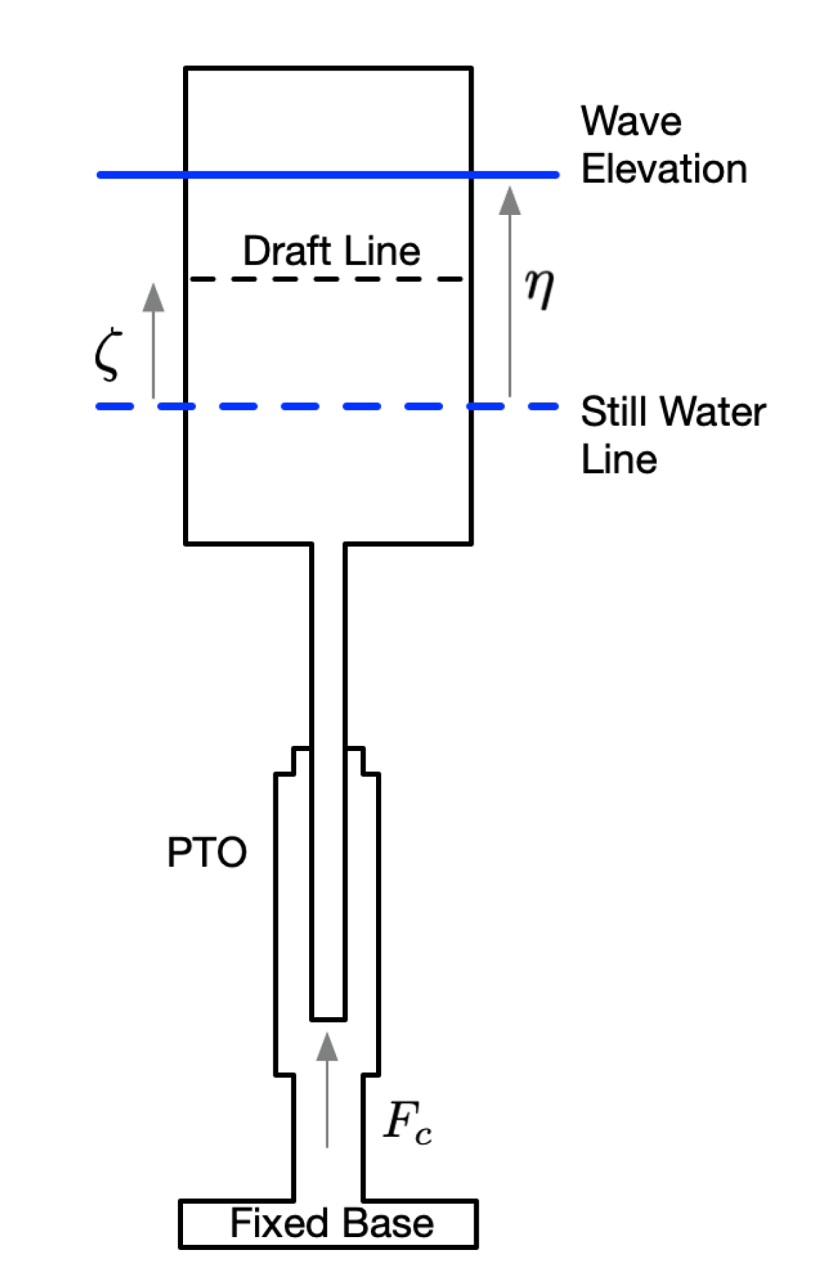
Figure 1.
Point absorber WEC with a cylindrical shaped buoy.
Figure 1.
Point absorber WEC with a cylindrical shaped buoy.
However, one often-cited practical limitation of CCC is that the buoy motion becomes larger than the model assumptions used in its derivation [
25,
31,
32,
42]. Thus, switching functions were used to keep the linear system bounded. In our work, we have managed to achieve that without the need for a switching function but by obtaining the proper initial condition of (
28) to drive our system to a stable limit cycle. To examine this, we will consider the optimality requirement that the buoy’s motion at least resides on a stable limit cycle.
Using (
37) the optimal acceleration is
which can be integrated twice to obtain its velocity and position
where
and
are integration factors.
To achieve a stable limit cycle, bounded motion,
, resulting in the optimal buoy velocity of (
43), the same result obtained from CCC [
19].
Achieving
depends on the excitation force expression,
, and the buoy initial conditions defined when the control law is activated. To examine this, consider a particular wave excitation force expression,
, used for a cylindrical point absorber buoy in [
37].
and its corresponding model
where
is the wave elevation.
From (
43), at time
,
To make
the initial velocity is
Thus, for any initial condition of the form
where
is any convenient initial position, a limit cycle is obtained having bounded periodic motion. However, it is always preferred to have the motion symmetric about
. This requires that
of (
43).
From (
43) with
at
Setting
, the initial condition of the position
is
The optimal, centered, periodic solution of (
45), with its required initial condition
, is
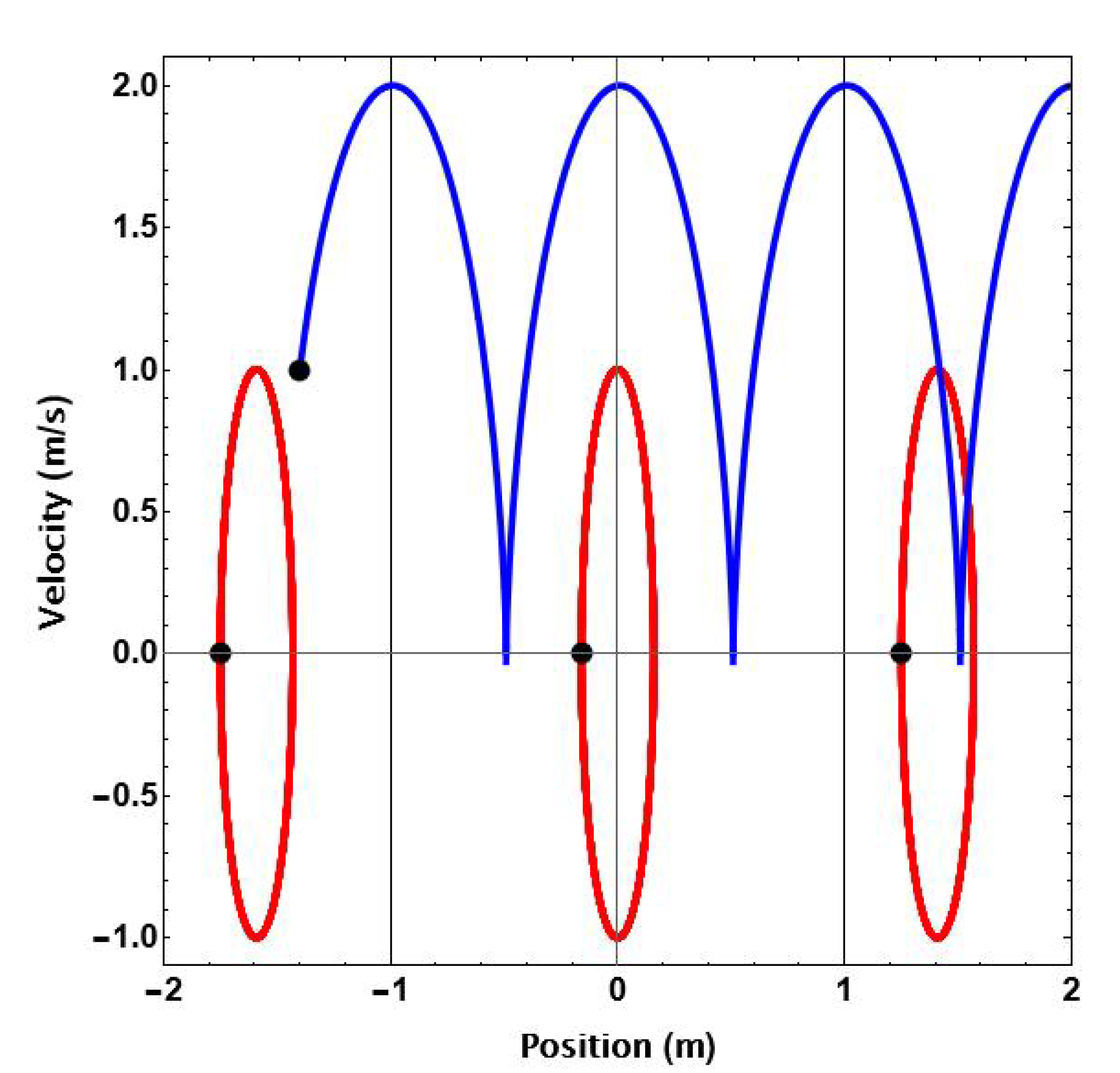
Figure 2 shows simulation results using the model parameters of
Table 1 for four different initial conditions indicated by black dots. When the initial condition lacks any initial velocity, [-1.75, 0], [-0.1594, 0], and [1.25, 0], the buoy exhibits bounded, periodic motion indicated by the closed, red contours in the phase space where [-0.1594, 0] produces the desired centered motion. The presence of initial velocity causes a gradual displacement growth over time, as shown by the blue trajectory of
Figure 2 for initial conditions of [-1.4, 1]. It’s important to note that the buoy oscillation frequency aligns with the input frequency for linear systems, resulting in the repetition of limit cycles every
T seconds.
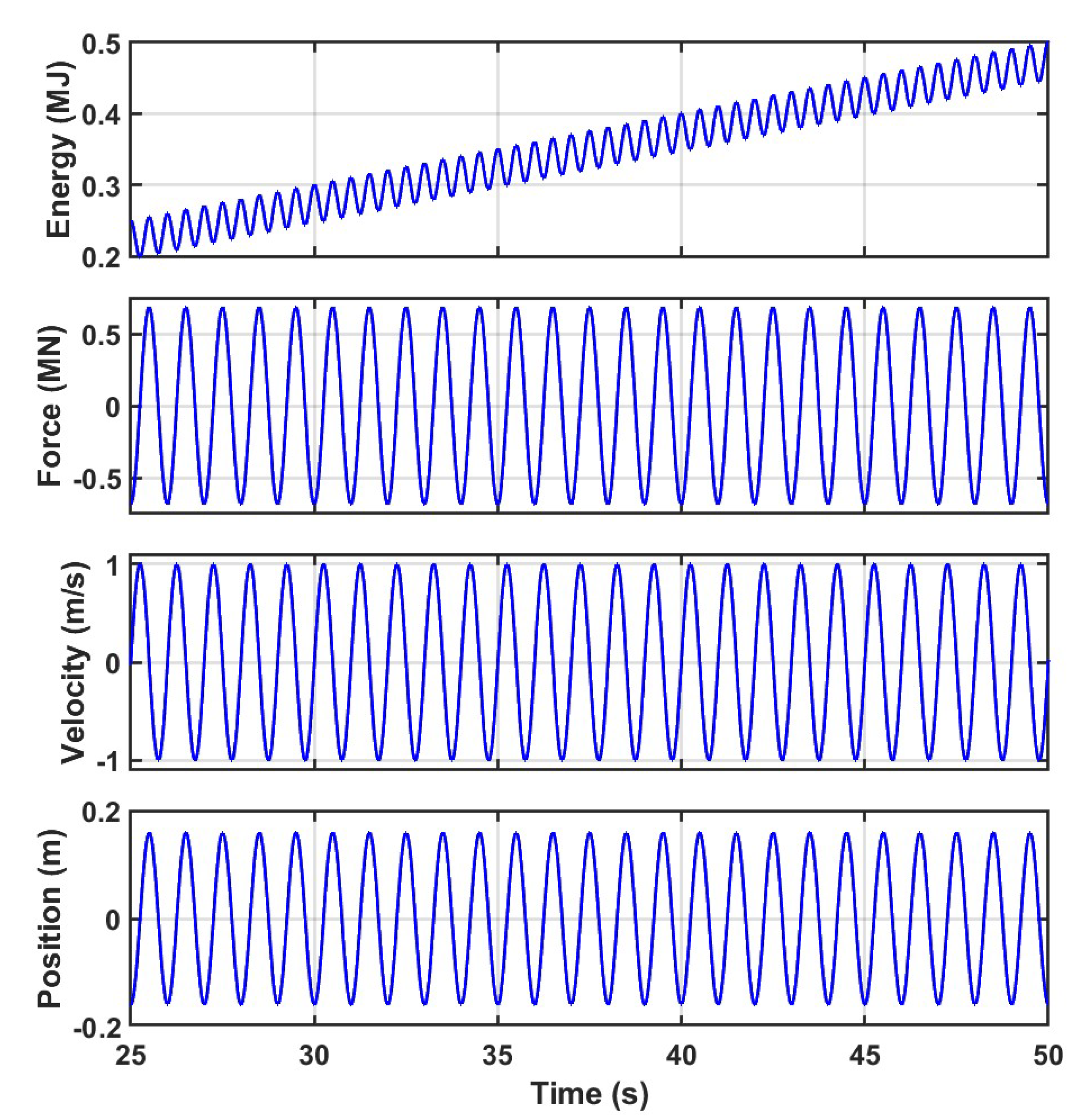
Figure 3 shows the steady-state simulation results obtained after applying the optimal control law with the centering initial conditions, [-0.1594, 0]. As expected, the periodic motion is bounded and centered about
. Furthermore, the energy extracted has a net positive slope.
In summary, to extract maximum energy using a linear point absorber, it is essential to apply the optimal control law of Equation (
40) while ensuring appropriate initial conditions to achieve a bounded periodic motion. Alternatively, a reference tracking controller can be used to follow the bounded analytical periodic optimal states. This can be easily achieved when
is analytically integrable.
3.4. Nonlinear Point Absorber WEC
Nonlinear WEC models introduce challenges, such as obtaining analytical solutions to compute initial conditions to achieve limit cycles. This arises when
, used in the optimal acceleration trajectory of (
37), is not integrable.
However, not all nonlinear systems exhibit this challenge due to the form of
. Consider a nonlinear system such that the
of (
31) is
where
is a nonlinear function and
is any integrable function of time. For example, the Duffing Oscillator has this form where the
are constant coefficients.
Based on (
52)
the optimal control law is
and the rest becomes identical to the linear system of (
45).
Unfortunately, this is a special case, and most models of nonlinear WECs possess nonlinearities of the form where i and j are integers.
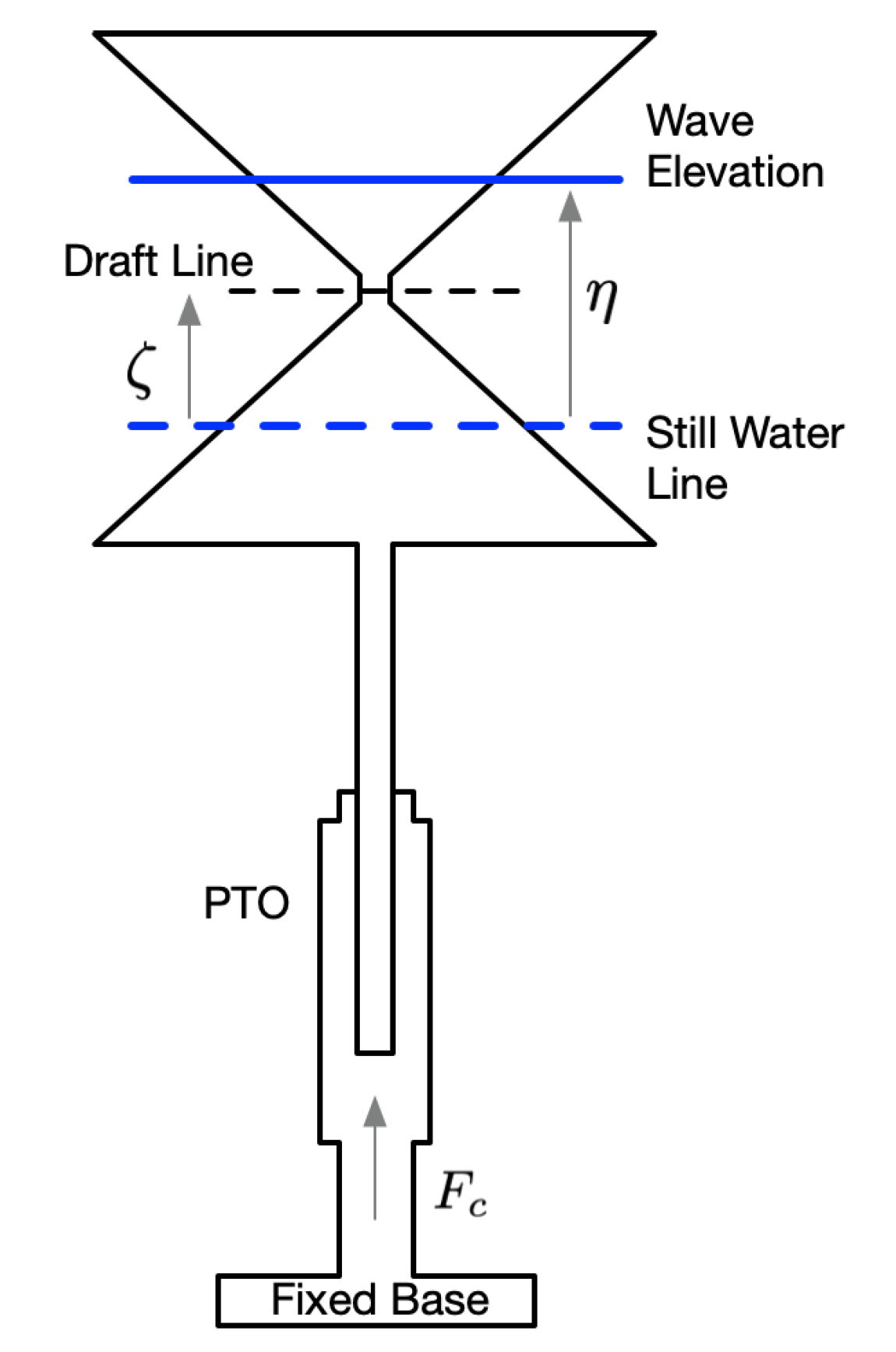
Consider the model of a nonlinear point absorber WEC with an hourglass-shape buoy [
37]
with
that is due solely to the buoyancy force. From (
34) the optimal control law is (
55)
with an optimal acceleration profile, from (
37), of
Since (
57) can not be integrated in closed form, obtaining expressions for the initial conditions that give limit cycle motion is impossible. Thus, we must resort to numerical techniques.
To numerically explore the initial condition space, the system of (
55) and the control law of (
56) were simulated using a third-order, explicit Runge-Kutta solver with a time step of 0.01 s with the parameters values of
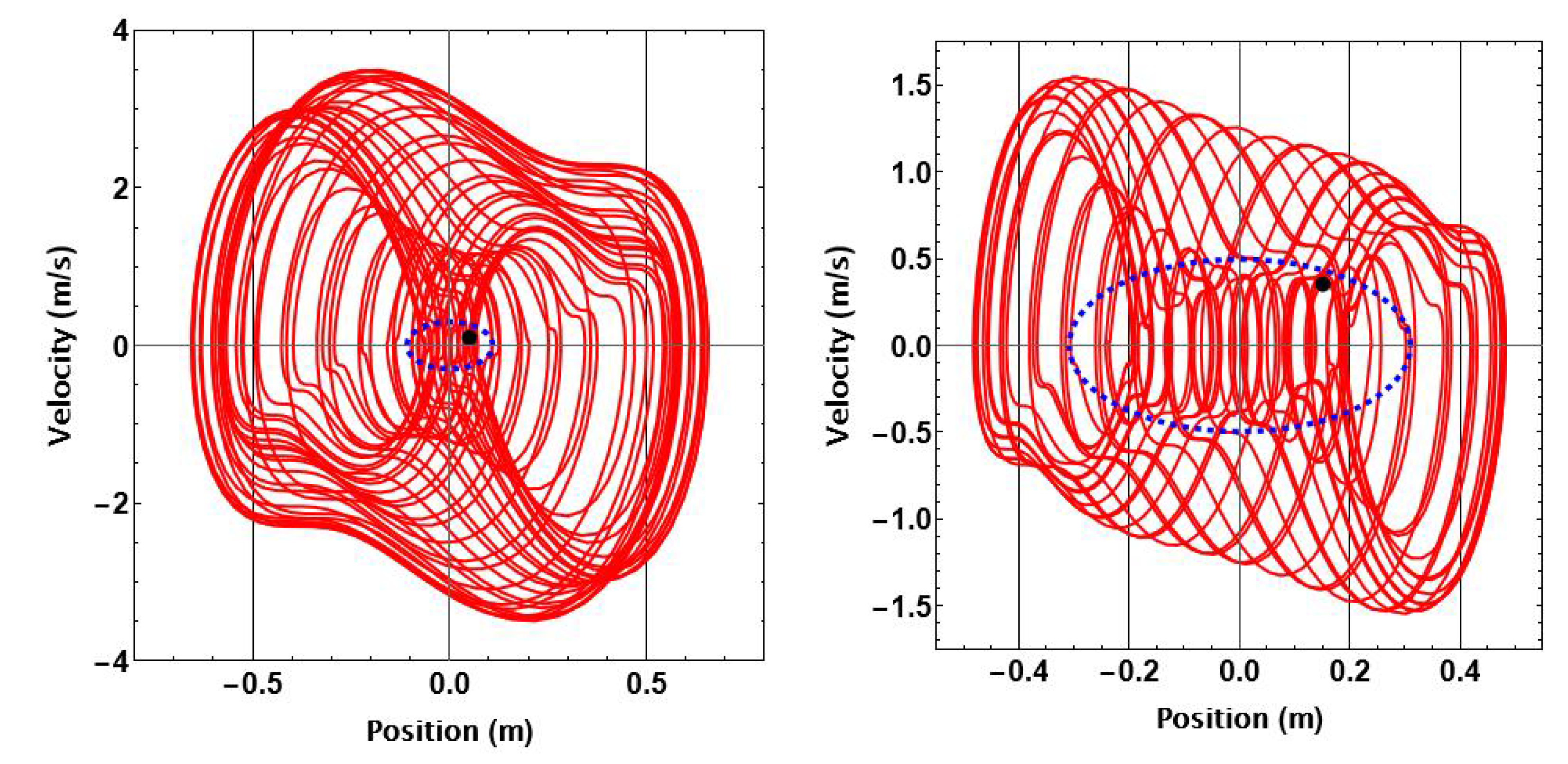
Table 1. The results for two different wave amplitude cases are shown in
Figure 5, where the simulation duration was 50 s. The left figure is for
, and on the right,
.
The blue dashed ellipses indicate the initial conditions resulting in limit cycles. The ellipse corresponding to the higher wave amplitude case has major and minor axes of and , respectively, in contrast to the smaller wave amplitude case, whose major and minor axes are and . The initial condition region increases with decreasing wave amplitude in these two cases. Other initial conditions may exist outside the ellipses that lead to a limit cycle. However, none were found using an extensive grid search of the phase space.
The red trajectories of
Figure 5 show buoy motions when the initial conditions are inside the ellipses, indicated by black dots. While these trajectories provide anecdotal information regarding position and velocity extremums they cannot be used to determine limit cycle existence.
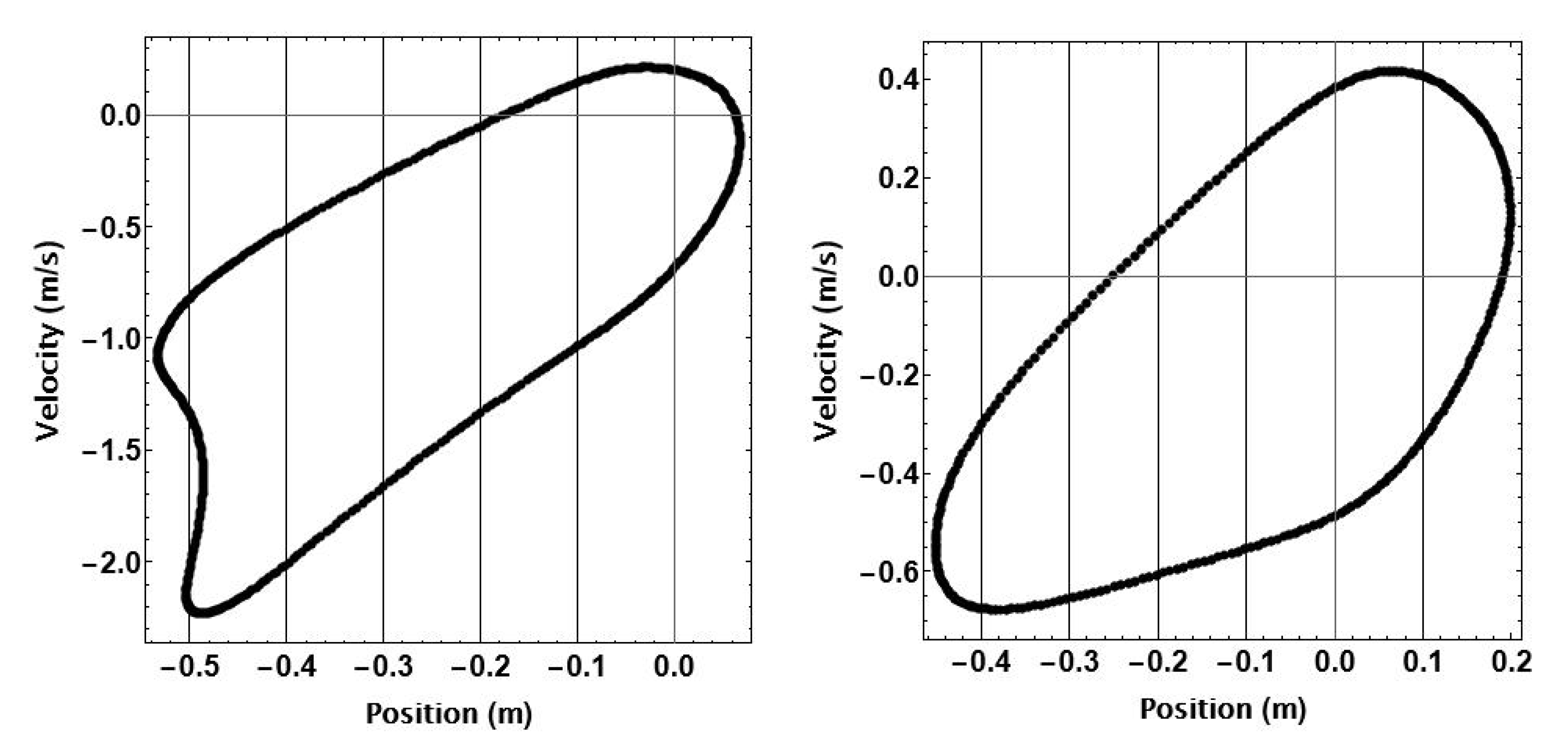
Poincare maps were used to confirm limit cycle behavior with the simulation time increased to 500 seconds. Given an initial condition, it is instructive to view the phase planes of
Figure 5 with time being along a third orthogonal axis. The red trajectories then move around the phase plane in the direction of increasing time. Poincare maps were made from sampling points on this three-dimensional trajectory at the excitation period of
seconds and are shown in
Figure 6 for the two initial condition cases of
Figure 5. Limit cycle motion is confirmed since the Poincare Maps are closed contours.
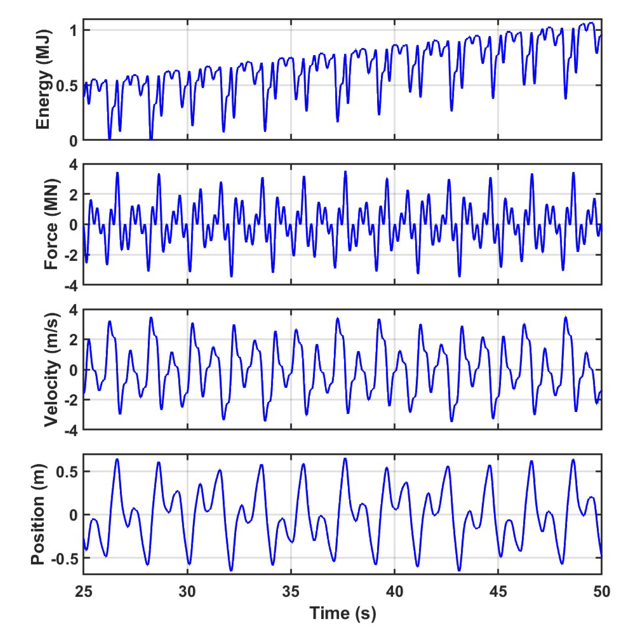
Figure 7 shows the dynamics of the nonlinear point absorber for a wave of amplitude
A upon the implementation of the optimal control law and choosing proper initial conditions, [0.05, 0.1], within the corresponding blue ellipse of
Figure 5. As with the phase plane plots of
Figure 7, periodicity is difficult to infer from this relatively short time duration. Once again, the energy time history has a net positive slope.
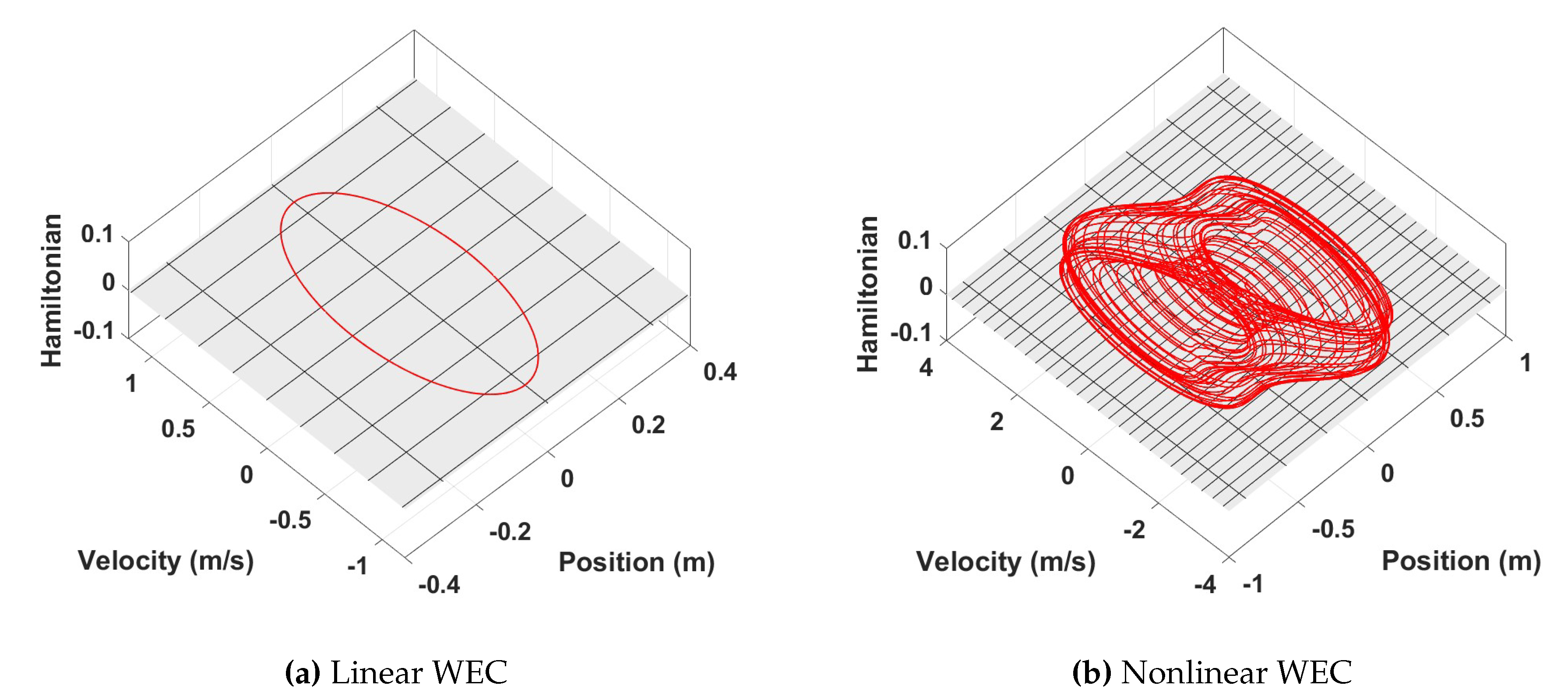
To further validate the optimality of the control law for both the linear and nonlinear cases, the value of the Hamiltonian is plotted in
Figure 8 and is zero for all time. This is a consequence of the PMP and ensures the simulated co-states match the solutions of the co-state differential equations of Equation (
35) arising from the Euler-Lagrange equations.
Overall, the presented figures and analyses demonstrate the promising performance of the optimal control approach, providing valuable insights into the dynamic behavior and energy production capabilities of the considered WEC systems.
4. Conclusion and Future Work
Optimal control analysis can be used to maximize the energy of a renewable source even when its second-order model is nonlinear and nonautonomous. To achieve bounded motion the initial condition region resulting in a stable limit cycle should be included in the optimal control analysis. The size and location of the region will, in general, be a function of the wave amplitude and frequency.
A relatively small set of initial conditions was found for the nonlinear hourglass-shaped buoy. It may be possible to find buoy shapes yielding larger initial condition regions extending the practical application of the optimal control law. Consequently, using the control law during shape optimization is one of the next steps to be exploited, finding the form of the nonlinearity that leads to a more extensive set of initial conditions. Finding a more systematic way to obtain initial conditions to drive the system to a limit cycle should also be explored. It should be noted that while the examples presented here used regular waves, the optimal control law form accommodates irregular waves as well.
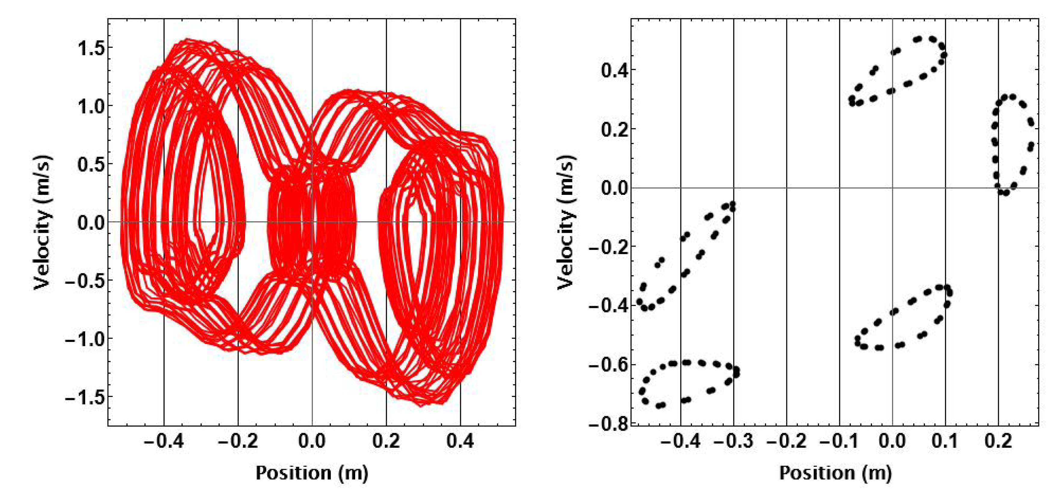
Initial conditions and wave parameters can result in intriguing limit cycle behavior that could be exploited for operational reasons. One case is illustrated in
Figure 9 for
and optimal initial conditions of [0.2, 0]. The buoy response progresses between the five closed contours of the Poincare map. Shaping the location, number, and size of the contours could be used to manage PTO bounds and motion constraints.
Author Contributions
Conceptualization, H.Y, K.N, G.P, and W.W; methodology H.Y, K.N, G.P, and w.w; software, H.Y and T.D.G; validation, H.Y, G.P and W.W.; formal analysis, H.Y. K.N, G.P; investigation, H.Y, and G.P.; writing—original draft preparation, H.Y T.D.G.; writing—review and editing. H.Y, T.D.G and G.P; visualization, H.Y.; supervision, G.P. W.W; funding acquisition, G.P. All authors have read and agreed to the published version of the manuscript.
