Submitted:
17 October 2024
Posted:
18 October 2024
You are already at the latest version
Abstract
Ship hull is a complex design where various types of complex loading conditions , like as Hydrostatic, Hydrodynamic, Wind, Wave and external internal bending forces. Ensuring structural integrity under these varying loads is essential for the ship structural safety and environmental protection. This review discusses the application of finite element methods(FEM) for the safety of ship hulls and analysis of ship hulls , emphasizing two significant studies that leverage ANSYS SOFTWARE to evaluate stress concentrations and deformation of hull under the various loading operation including the wave and wind forces and the stress. The findings Underscore the importance of analyzing both local and global aspects of ship structures to improve design practices and enhance safety standards. In this paper we mostly focused on a general cargo ships hull structure, Grounding of a ship.
Keywords:
ship hull
; finite element methods
; ANSYS
; RHINOCEROS
; MAXSURF
; CSM structural analysis
; grounding
; general cargo ship
; stress concentration
; deformation
Introduction
Strength, Stability and Speed are considered as the complex things for any design and construction specially for ship this is very important. Among this three factors Strength are totally depends on the construction material stability mostly depends on the analysis of structure and speed depends on the strength and stability . Naval Architect who mostly design the ships devote considerable resources to these aspects to mitigate risks associated with structural failures. Catastrophic failures can arise from excessive bending moments, hull corrosion, and fatigue . The International Maritime Organization(IMO)And various classification societies provide the guidelines and standard to ensure adequate strength against all the factors. Historically, structural analysis has evolved from classical theories of elasticity to modern numerical simulations, such as the FEM which can effectively address the complexities of ship structures. General cargo ships among the other ship types in the global aspects in 2002 , it accounted for approximately 37% of the total number of vessels in the world merchant fleet and around 11 % in terms of deadweight tonnage. The procedure of 3D FEM structural analysis of general cargo ships as a tool of improving the hull structure strength and stability. For a general cargo ship hull structures focusing on the key insights from recent studies employing FEM, particularly focusing on ANSYS, MAXSURF and CSM analysis . The analysis of the cargo ship is similar to the analysis of the container ships.
2. Literature Review
2.1. Historical Content
The foundation of structural analysis can be traced back to the classical theories of beams and columns established by Euler and Bernoulli in the 18th century and claude-Louis Navier gave the relation between the cross section and the bending stiffness parameters in 1819 which paved the way for practical solution to structural problems. Over the years both analytic and numerical methods have been developed to analysis ship hull , structures for a better strength, stability and load distribution.
2.2. Modern Structural Analysis Techniques
Today FEM as a powerful tool for analyzing complex ship structures in 3D various software including ANSYS, RHINOCEROS, MAXSURF, ABAQUS and VeriSTAR CSM (developed by classification society BV). The analysis of general cargo ship using this VeriSTAR CSM Edition December 2003. This tool allows the detailed modeling of ship components and consideration of various loading which effect the ship hull and the strength of the overall structure. The relation between loading conditions and structural responses is complex ,necessitating computational methods to simulate realistic scenarios effectively.
3. Comparison of Method
FEM provides systematical approach to structural analysis by breaking down complex geometrics into many sections or smaller part and elements. Ship hull as a complex structure , this involves modeling the hull as a slender beam subjected to various loads, friction, stress including static, dynamic, and environmental forces, wave forces etc.
Those papers have two outlines’ methods for analyzing the ship hull and the structure
- Individual structural member analysis : Analyzed every structural component separately.
- Global Structural Analysis : Analyzed the whole structure and the behavior.
4. Case Study :
4.1. Non-Uniformly Distributed Load
In the study an arbitrary ship hull of a general cargo ship with a dimension of 100m length, 10m breadth, and 7.5m depth, was analyzed under a non-uniformly distributed loads using ANSYS, CSM and RHINOCEROS. The loading conditions including localized pressure forces and uniformly distributed loads across the various section of the hull and the full structure. The results indicate the significant deformation at the midship section areas and the edge stress concentration.
Figure 1.
Structural analysis for different load distribution.
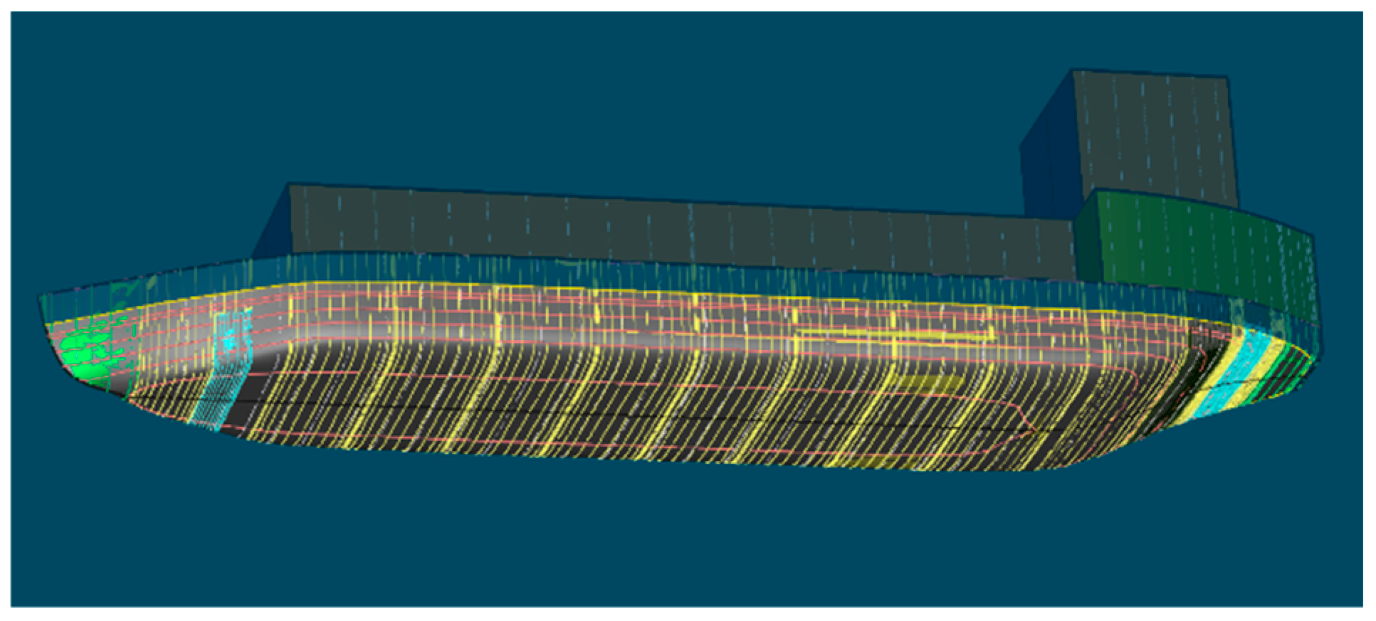

Table 1.
results for case study 1.
| Type | Maximum | Minimum |
|---|---|---|
| Axial Deformation | 0.164x10⁻⁵ m | -0.721x10⁻⁶ m |
| Lateral Deformation | 0..239x10-5 m | -0.238x10⁻⁵ m |
| Von-Mises Stress | 0.261x10⁷ Pa | 746.274 Pa |
4.2. Case Study 2: Wave Crest Loading
In a subsequent study an 80 m long hull was analyzed under wave crest and through loading conditions applied at the fore and aft perpendiculars of the ship. The analysis show that the stress distribution was heavily influenced by the load distributions in the midship areas and showing the highest susceptibility to failure.
Figure 2.
Midship section for different load distribution.
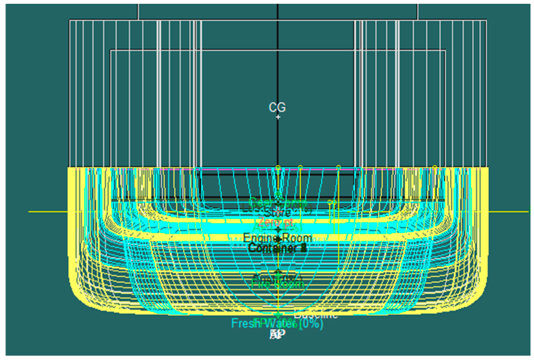
Table 2.
results for case study 2.
| Type | Maximum | Minimum |
|---|---|---|
| Total Deformation | 2.1424x10⁻⁶ m | 0 m |
| Von-Mises Stress | 1137.3 Pa | 21.559 Pa |
4.3. Case Study 3: Hogging Condition
Maximum accident occurs in the cargo ship or the challenge for the designers and the production house is to overcome the hogging and sagging condition. This is a critical analysis involved a hull or the structure under hogging conditions, with the maximum wave crest positioned at the midship. This Scenario resulted in significantly Higer stress values compared to previous loading conditions and this indicate a greater risk of structural failure.
Table 3.
results for case study 3.
| Type | Maximum | Minimum |
|---|---|---|
| Total Deformation | 3.8838x10⁻⁴ m | 0 m |
| Von-Mises Stress | 5.53x10⁵ Pa | 3.4766 Pa |
Discussion
The main purpose of the analysis is to find out the structural strength, Hull stability and the sustainability. Highlighting the critical importance of conducting through structural analyses of ship hulls to mitigate the risks of failure. The relation between the applied force, load distributions and developed stresses observed in the case studies emphasizes the need for careful consideration of loading conditions during design. Particularly, the analysis of loadcase, hogging effects reveals that this condition poses a significantly greater threat to structural integrity than sagging, warranting targeting design improvements.
Conclusions
The collection of studies highlights that the critical role of FEM in ensuring the structural integrity of ship’s hull and structure under various challenging condition. From global structural assessments of cargo ships to detailed analysis of ship grounding and stress concentration at edge corners, FEM has proven method to identify weak points and guiding necessary reinforcements. Furthermore, grounding studies revealed that areas between girders are particularly vulnerable to damage, reinforcing the importance of strengthening. Numerical method not only enhance accuracy but also offer cost efficient solutions by minimizing physical testing, although a configuration is needed to maintain reliability. These insights provide valuable contributions to improving safety and durability of ships and finally help to prevent structural failures and minimize the associated environmental and economic risks.
Future Works
Further research scope is focusing on refining loading and load distribution models and exploring additional environmental factors that can affect the ship hull and the overall structure. Integrating real time monitoring systems with structural analysis tools may also enhance the ability to predict and prevent failures of the structure.
References
- M. M. R. R. S. K. a. R. Islam, "Structural Analysis of a Ship on Global Aspect Using ANSYS," in AIP Conference Proceedings, Dhaka, 2017.
- J. P. T. U. I. SENJANOVIĆ, "Structural Analysis of a General Cargo Ship," BRODOGRADNJA, pp. 28-33, 2009.
- R. P. B. C. D. M. B. S. Y. B. A. F. Z. J. M. Sohn, "Structural Analysis of the Double Bottom Structure During Ship Grounding by Finite Element Approach," Latin Amirican journal of solids and structures, pp. 1106-1123, 2017.
- P. R. a. E. Rizzuto, "Ship Design & Construction," in Analysis and Design of Ship Structure, vol. 1, 2003, pp. 18.2-18.
- Phelps, Determination of Wave Loads for Ship Structural Analysis, Australia: DSTO Aeronautical and Maritime Research Laboratory, 1997.
Disclaimer/Publisher’s Note: The statements, opinions and data contained in all publications are solely those of the individual author(s) and contributor(s) and not of MDPI and/or the editor(s). MDPI and/or the editor(s) disclaim responsibility for any injury to people or property resulting from any ideas, methods, instructions or products referred to in the content. |
© 2024 by the author. Licensee MDPI, Basel, Switzerland. This article is an open access article distributed under the terms and conditions of the Creative Commons Attribution (CC BY) license (https://creativecommons.org/licenses/by/4.0/).
Copyright: This open access article is published under a Creative Commons CC BY 4.0 license, which permit the free download, distribution, and reuse, provided that the author and preprint are cited in any reuse.


