1. Introduction
In recent years, human-robot collaboration (HRC) has emerged as an alternative production paradigm to manual labor, particularly in high-wage countries where manual production processes have become significantly more challenging due to shortage of skilled labor and increasing labor costs [
1,
2]. This transition is motivated by the necessity to partially automate assembly processes, thereby sustaining competitiveness in the global market. However, the process of planning HRC assembly sequences is complex and time-consuming as it is mostly a manual process that has to be repeated for every new product from scratch [
3].
This complexity and time-consuming nature is a result of several factors. First, it arises from the inhomogeneity of different existing information sources used in the planning process. Integrating heterogeneous data sources such as CAD models [
4], 2D drawings, and written assembly instructions into a coherent and efficient plan is a significant challenge. Second, task allocation is complex requiring careful consideration of the respective skills of robots and humans to ensure the best fit for each task [
5]. Third, the chosen mode of human-robot interaction such as synchronization, cooperation, or collaboration adds another layer of intricacy. Fourth, the demand for mass customization intensifies these challenges by necessitating tailored assembly sequences for a wide variety of products which in turn requires frequent and dynamic adjustments to the assembly process without extensive reprogramming [
6].
In our previous work [
7], we used a non-automated method to split a manual assembly sequence into tasks for humans and robots. A manual criteria catalogue [
8] was used to allocate tasks to humans and robots and to create an assembly sequence based on engineering judgement.
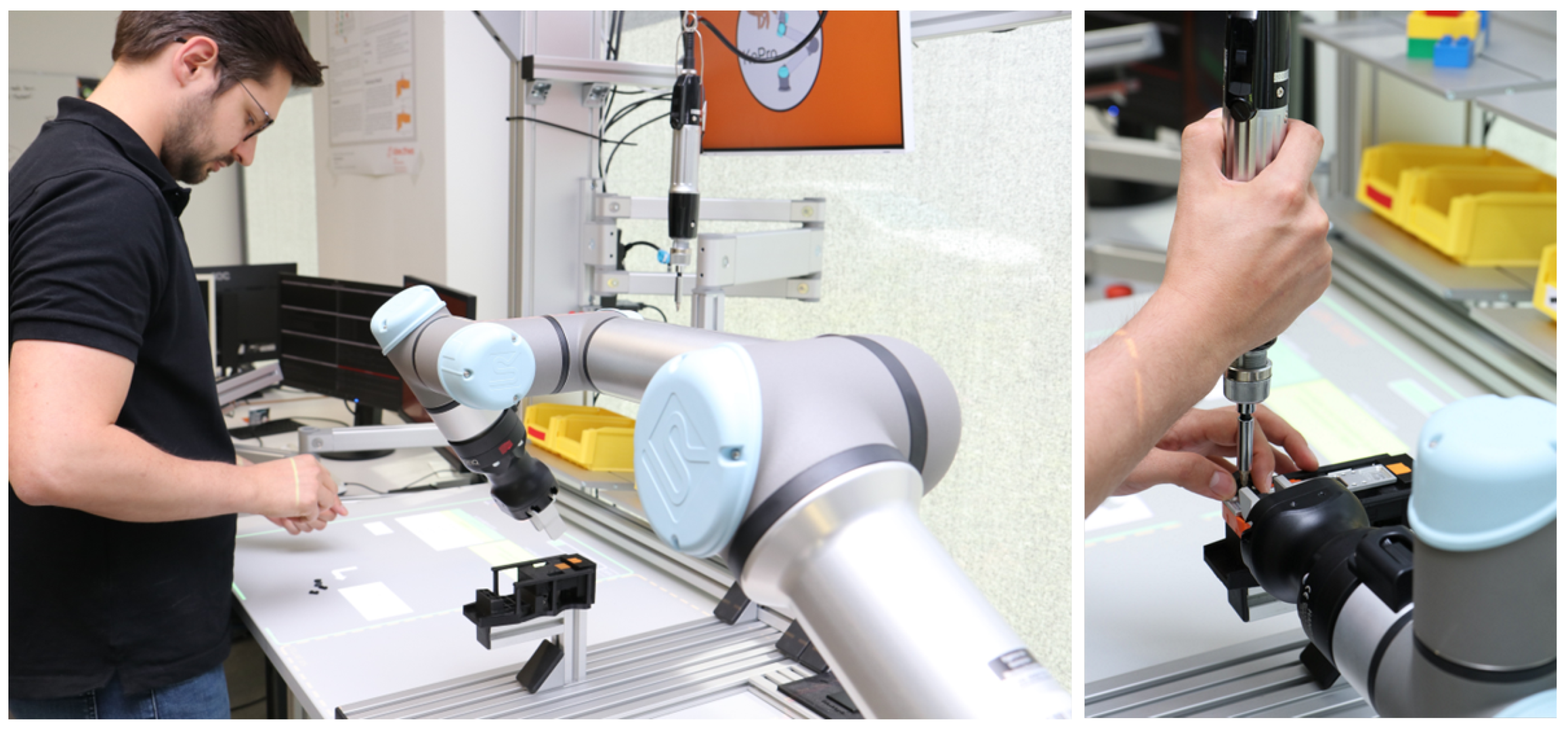
Figure 1 shows the successfully applied task allocation to a use case from the medical industry. During the assembly sequence planning process process, challenges arose due to the need for expertise and deep familiarity with the product which other researchers have found as well [
9,
10].
For manual assembly processes, the automated generation of assembly plans has been addressed in the literature, e.g. [
11,
12,
13]. Initial approaches using extracted CAD information for HRC sequences have also emerged, e.g. [
3,
14]. However, most of those approaches are tied to specific CAD formats [
12] or specific software [
13]. We aim at a general approach using CAD information in meta-format STEP AP242 [
15], 2D drawings (DXF) and assembly instructions (PDF/Excel) covering a large amount of the information required for HRC assembly planning [
16]. Missing information is detected and an expert is guided via a dashboard interface to manually enrich the data.
The objective of this work is to partially automate and simplify the HRC planning process, reducing its complexity and time-consuming nature. By streamlining the planning process for HRC assembly paradigms, this work aims to facilitate the transition from current manual assembly processes to more efficient automated systems, thereby promoting widespread industry adoption. To address this challenge, a framework is presented that generates dynamic HRC assembly plans. In this context, “dynamic" implies that the framework generates multiple plans involving various ways in which humans and robots work together, along with different arrangements of steps within the assembly plan. For instance, this allows an adaptation of the assembly plan during runtime. The framework uses four heterogeneous data sources: 1) CAD data, 2) 2D drawings, 3) written assembly instructions, and 4) knowledge from a product expert. The contributions of this work are three-fold:
Presentation of a novel framework “Extract-Enrich-Assess-Plan-Review” (APR) that generates multiple alternative assembly sequence plans enabling a dynamic human-robot work flow.
Illustration of the ability to generate assembly sequences for three different human-robot interaction modalities by applying it to a toy truck assembly use case.
Evaluation results with respect to a) the level of automation of the planning framework, and b) cycle times for three interaction modalities.
A preliminary version of this work was published in [
17]. We extended it by 1) adding two more input sources to the framework, 2) creating a hierarchical data structure facilitating the augmentation process for the expert, 3) adding an additional HRI modality, 4) extending the abilities of the output layer, and 5) evaluating the updated
APR framework experimentally.
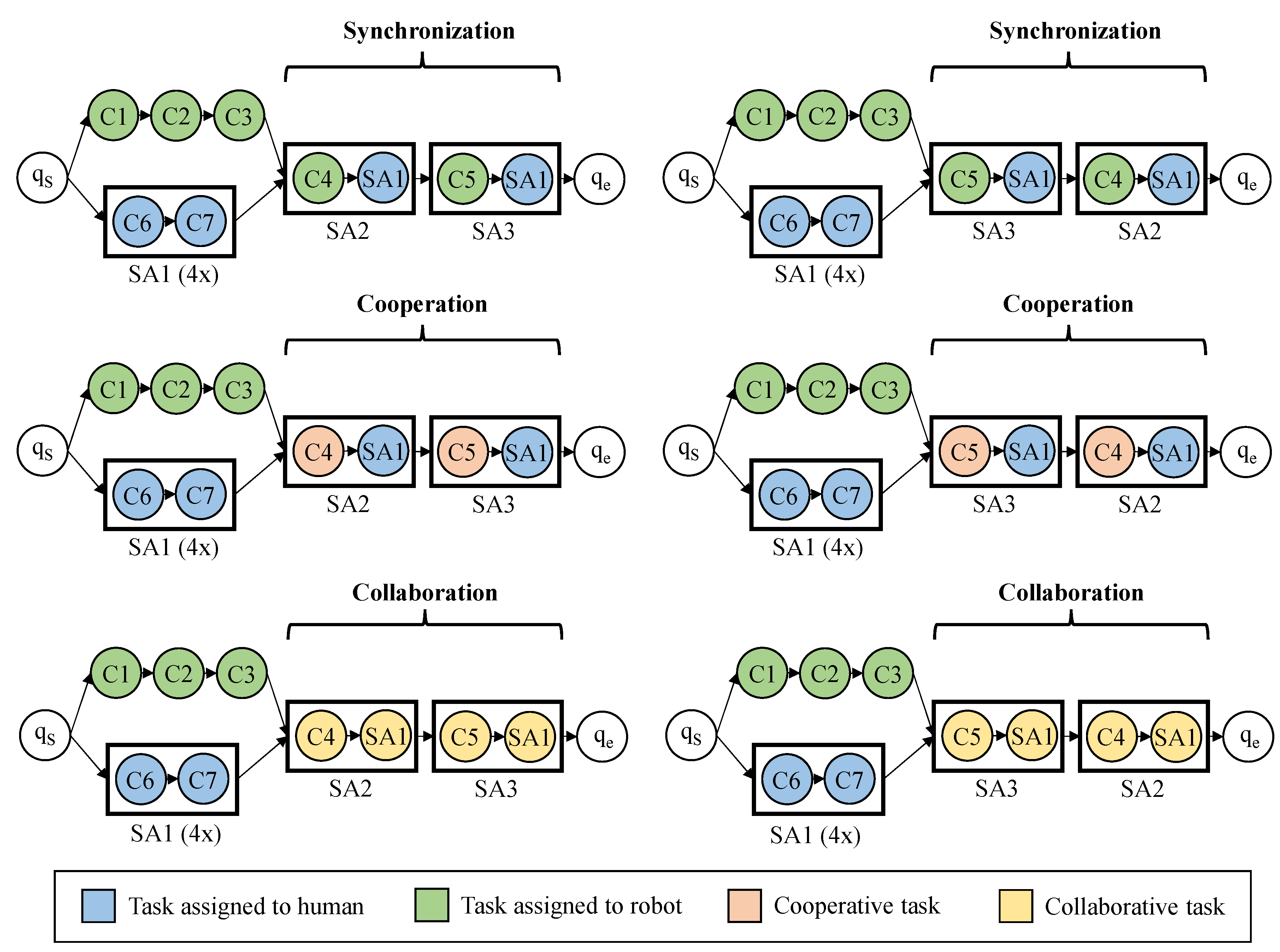
In the improved framework, we distinguish three types of human-robot teamwork: Synchronization, Cooperation and Collaboration. In all cases, human and robot work in close physical proximity. In Synchronization mode, each agent works sequentially in a shared work space on separated assembly steps. In Cooperation mode, they work in the shared area at the same time but on separated assembly steps. In Collaboration mode, both agents simultaneously work on the same assembly step.
Figure 2 (right) shows an example for Collaboration.
The remainder of this paper is organized as follows.
Sec. 2 presents related work. The toy truck use case is described in
Sec. 3. The system architecture is detailed in
Sec. 4 and validated using our use case in
Sec. 5. Finally,
Sec. 6 concludes the paper and discusses future work.
2. Related Work
Our work is centered on holistic Assembly Sequence Planning (ASP) for Human-Robot Collaboration, with an emphasis on frameworks that utilize CAD data and Methods-Time Measurement (MTM). These frameworks facilitate effective collaboration and enable flexible, dynamic workflows during the assembly process.
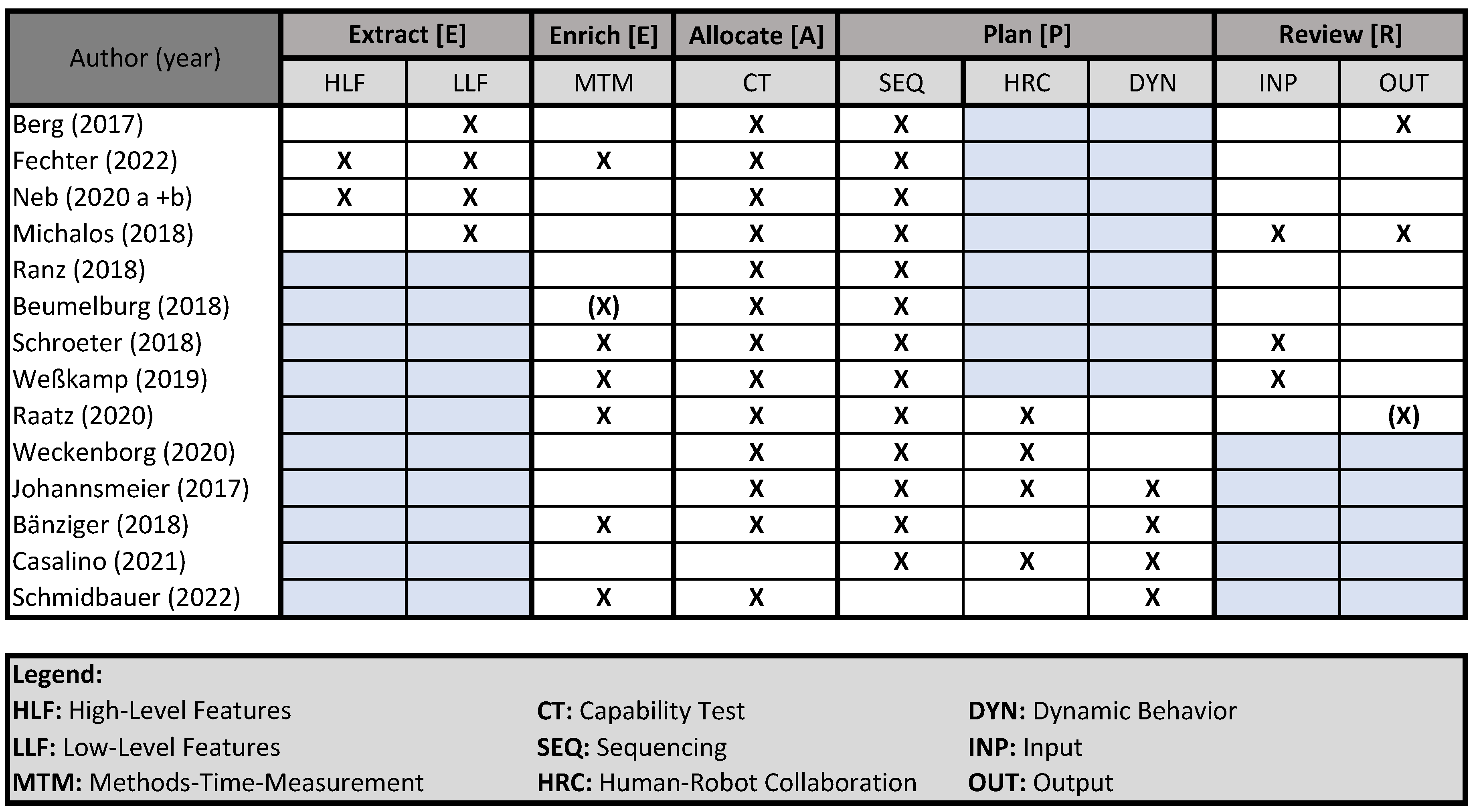
Figure 3 presents a summary of relevant research in these areas.
While almost all papers perform a capability test and sequencing, works in the field of CAD-based planning (
Extract) do not generate dynamic plans [
18] and the interaction modality of collaboration is also omitted. Works on dynamic ASP and HRC, on the other hand, often do not use experts to adjust the results (
Review), the only exception being the work by Raatz et al. [
19].
2.1. CAD-based Assembly Sequence Planning
To our knowledge, few approaches offer a holistic method for generating Human-Robot Collaboration workflows from CAD data (e.g., [
3,
20,
21,
22]). Typically, these methods extract low-level features such as hierarchical structures, component names, shapes, or colors to create relationship matrices or perform capability assessments for HRC tasks. For instance, Fechter et al. utilize both low-level features (e.g., geometry and weight) and high-level features (e.g., joining operations) to allocate assembly tasks to humans, robots, or a combination of both. Their system relies on a carefully curated database.
In contrast, our framework is designed to handle incomplete data by incorporating an expert-in-the-loop. This expert reviews both the input data and the generated results, similar to the approach taken by [
21]. Consequently, our method is better equipped to handle variations in data quality and completeness.
In addition to data sourced from CAD files, information can also be derived from 2D drawings. The AUTOFEAT algorithm developed by Prabhu et al. [
23] enables the extraction of both geometric and non-geometric data from these drawings. Expanding on this, Zhang and Li [
24] present a method for establishing associations among data extracted from DXF files. Regarding product variants, several researchers have proposed innovative techniques for predicting compliant assembly variations, including the use of geometric covariance and a combination of Principal Component Analysis (PCA) with finite element analysis [
25,
26]. However, these methods do not address data extraction for Human-Robot Collaboration in the context of assembly sequences.
In summary, while numerous innovative methodologies have been developed in the literature for different facets of CAD modeling and feature extraction, a generic, user-friendly tool for HRC sequence planning accommodating a wide range of product variations is still needed. Our proposed methodology tackles these challenges by utilizing multiple information sources for effective data acquisition and creating an advanced data model.
2.2. Holistic Approach to HRC Assembly Sequence Planning
The planning systems for HRC found in the literature largely adhere to a framework initially proposed by Beumelburg [
27]. The process begins with the creation of a relationship matrix [
20,
28], which may also be assumed as given [
3,
29]. Next, a capability assessment identifies which resource— whether robot, human, or a combination of both—can perform each assembly step. During scheduling, suitable resources and processing times are assigned to the assembly tasks. Decision-making in this scheduling phase often incorporates weights [
3,
20,
29] that reflect higher-level objectives such as cost, time, and complexity [
29], as well as goals like maximizing parallel activities, increasing automated tasks, minimizing mean time [
20], or managing monotony and break times [
19].
None of the previously mentioned methods consider the generation of dynamic assembly sequences. As highlighted by Schmidbauer [
18], only a limited number of approaches exist for developing dynamic assembly sequences tailored to HRC scenarios [
5,
30,
31]. Additionally, few strategies focus on generating sequences specifically for HRC [
19,
30,
32]. The detailed system framework proposed in this paper streamlines the process by partially automating the workflow from CAD, DXF, and PDF/Excel data to produce a comprehensive dynamic assembly sequence plan (ASP) for HRC.
2.3. HRC Assembly Sequence Planning Based on MTM
To enable the planning of robot cycle times in a HRC setting, variations of Methods Time Measurement (MTM) [
33] are frequently employed. The MTM method facilitates the estimation of processing times for individual work steps performed by both robots and humans, eliminating the need for complex simulations or real-world measurements.
Schröter [
28] builds upon Beumelburg’s framework by incorporating specially designed robot process modules to calculate target times based on the MTM-1 system [
34]. Weßkamp et al. [
35] present a framework for planning HRC ASP based on the criteria catalogue also used in our previous work [
8] and a simulation environment to calculate ergonomic factors and cycle times. For the robot time estimation they use a modified MTM-UAS approach that treats robot actions like human actions but multiply the results with a factor
f, since the robot is usually slower than the human in HRC. Weßkamp present a simple approach to get a first estimation of possible human-robot interactions.
Komenda et al. [
36] evaluate five methods for estimating HRC cycle times, including those proposed by [
19,
28,
35], using data from real-world applications. Their findings indicate that Schröter’s MRK-HRC and Weßkamp’s modified MTM-UAS yield comparable results for overall cycle times, both achieving a 5% error margin, despite Weßkamp’s method being simpler. The authors critique MTM-based cycle time estimation methods for HRC, arguing that these are designed for high-volume production scenarios with averaged-trained workers, which is often not applicable in HRC contexts. They advocate for simulation-based methods instead. Given our objective of distributing tasks between humans and robots with minimal expert input, we adopt Weßkamp’s modified MTM-UAS as our baseline for estimating robot cycle times.
3. Experimental Setup: Assembly Use Case
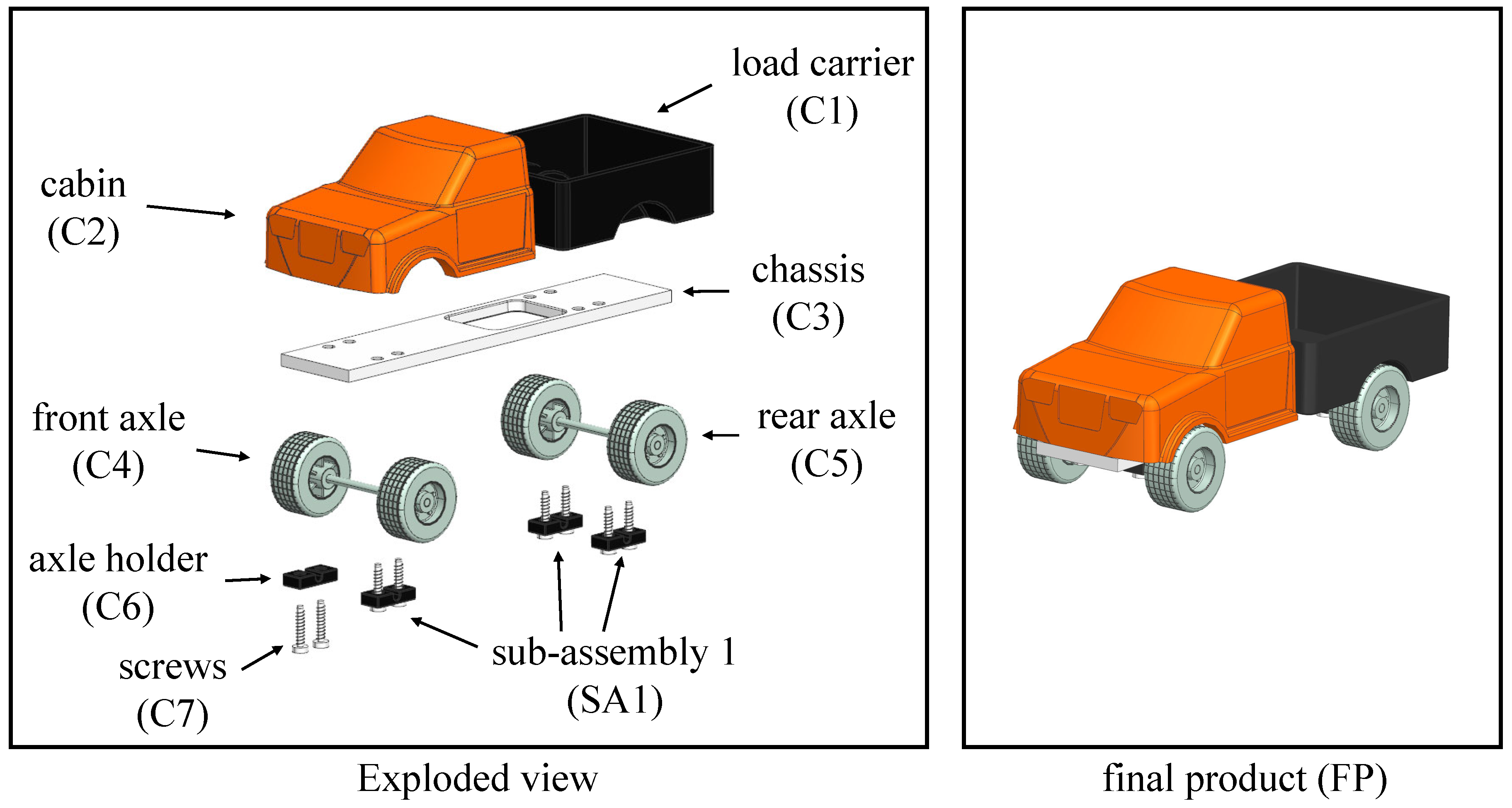
The E²APR framework outlined in this paper is demonstrated through a representative use case: the assembly of a toy truck.
Figure 4 presents an exploded view of the assembly. We define the following terminology: a
component (C) is an indivisible atomic unit. A
sub-assembly (SA) is formed from at least two
components or other
sub-assemblies (SA) that are connected through various actions (such as bolting, welding, or bonding). The
final product (FP) comprises one or more
sub-assemblies and
components.
4. Detailed System Framework
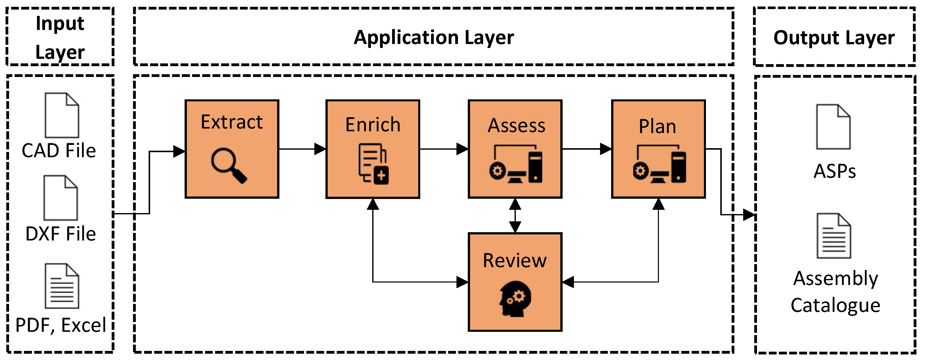
The detailed system framework, illustrated in
Figure 5, comprises three layers: the Input Layer, the Application Layer, and the Output Layer. Data flows from left to right. The input data includes 1) CAD files in STEP format [
37], 2) 2D drawings in DXF format, and 3) assembly instructions for manual assembly in PDF/Excel format. The Application Layer processes this data through units known as Extract, Enrich, Access, Plan, and Review. The Review unit involves a domain expert, who contributes by filling in missing information and evaluating the outputs of each unit. The final output of the E²APR framework consists of a set of dynamic assembly sequence plans for three different human-robot interaction modalities, along with an assembly catalog that provides detailed information about the assembly steps and components.
4.1. Extraction Unit
The Extraction Unit processes diverse input data for feature extraction and assembly information. This includes 1) CAD files in STEP formats (AP203, AP214 and AP242), 2) Drawing Interchange File Format (DXF), and 3) a combination of Portable Document Format (PDF) and tabulated Excel data [
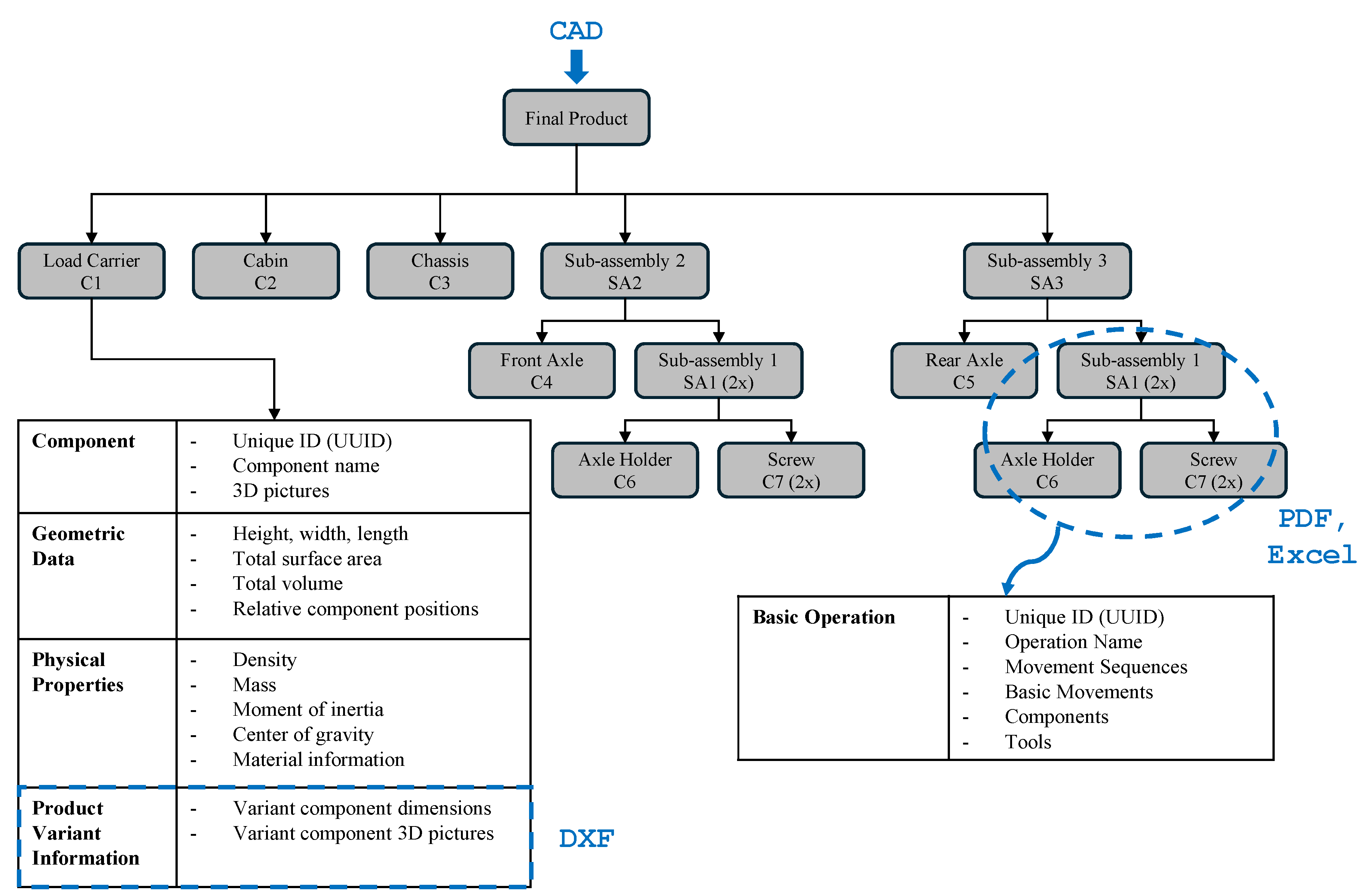
16]. The unit’s output is a data model of the product as shown in
Figure 6. The model comprises detailed component information, assembly information and a hierarchical structure designed to identify the order and components for each sub-assembly.
Our method for extracting CAD data builds upon the research of Ou and Xu [
38], utilizing assembly constraints and contact relationships among the components. By employing a disassembly-oriented strategy [
39] on the final product, we can dissect the assembly into smaller sub-assemblies and atomic components, revealing their hierarchical positioning within the final product. As a foundation to extract the CAD information, we use the Open CASCADE Technology library
1.
We extend this approach by incorporating additional information about product variants from accompanying DXF files. To achieve this, we developed a variant extraction algorithm that automatically extracts relevant data from the DXF files and enriches the component information accordingly.
One further extension involves integrating supplementary information about the assembly steps from pre-existing manual assembly instructions. These instructions include detailed information about the
components needed for an assembly step,
action verbs (e.g. “join" or “screw") and used
tools (e.g.“screwdriver" or“hammer"). We use a model named
de_core_news_sm2, which is trained on German newspaper reports, to identify those keywords from assembly instructions provided as Excel or PDF files. Since the standard model was not able to identify
tools from the assembly instructions, we retrained the model using transfer learning with synthetic data generated from ChatGPT
3. Example sentences (blue) with a
tool and its exact position in the sentence, determined by its start and end character (gray) and labeled as such, served as input:
Use the screwdriver to turn screws into the surface. , entities: [(8, 19, TOOL)]
By implementing the updated model, we achieved an accuracy rate of up to 90% for detecting the keywords. All extracted information from CAD, DXF and PDF/Excel are combined in an assembly step catalogue and are stored in a MongoDB
4.
4.2. Enrichment Unit
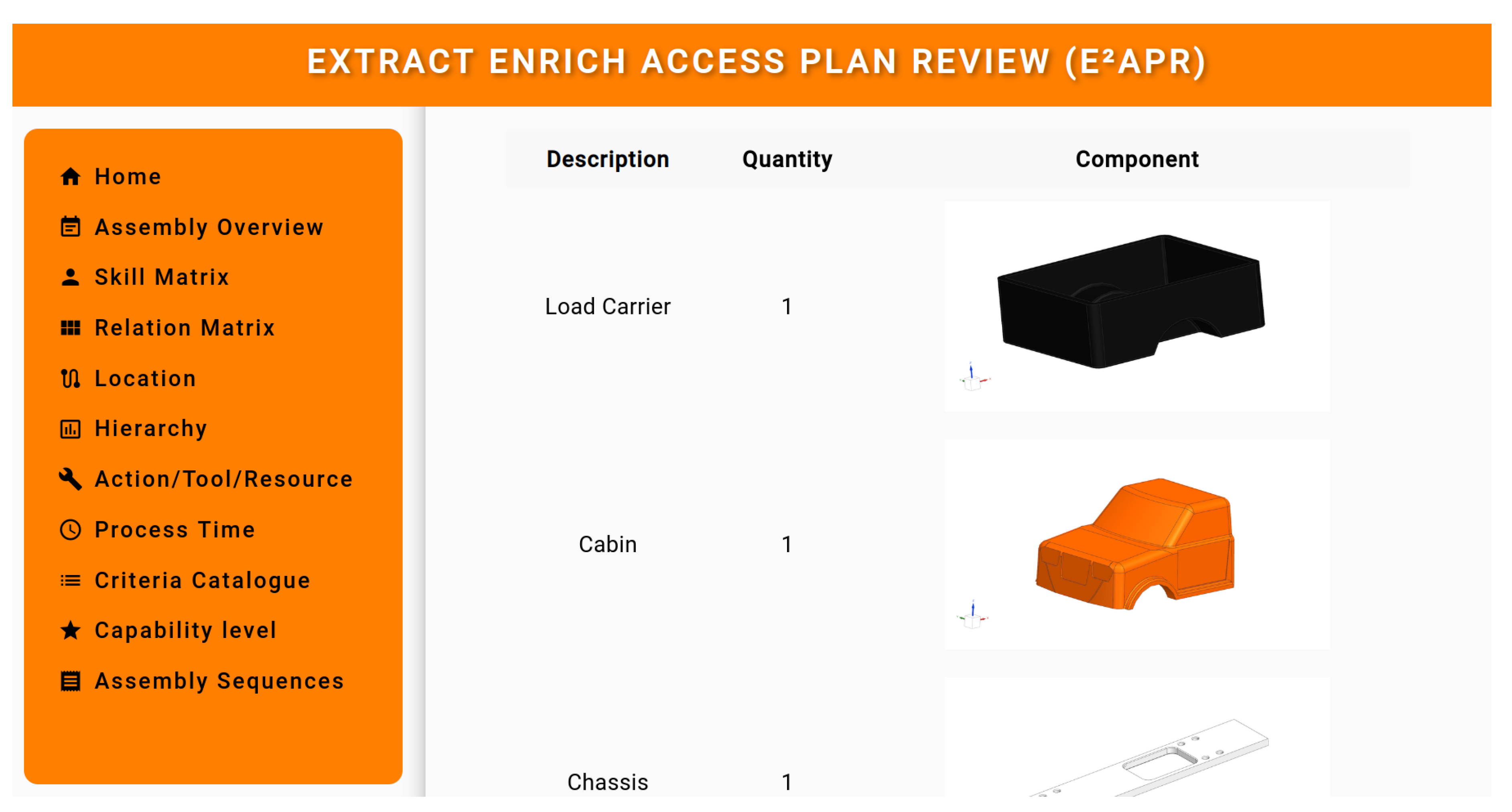
Given that all variations of CAD input data must be managed and that CAD files are often not well-maintained in practice, it is essential to address incomplete data. We have created a dashboard that allows product experts to incrementally add the missing information. The expert can modify all components, actions, and tools for a specific step or add missing information which are highlighted in the dashboard.
Figure 7 shows the dashboard’s navigation options.
Detailed assembly step information, as shown in
Figure 8, determines the atomic tasks for each assembly step. This information is used to calculate the process times for both human and robot and specifies the possible forms of human-robot interaction, which will be further discussed in
Sec. 4.4.3.
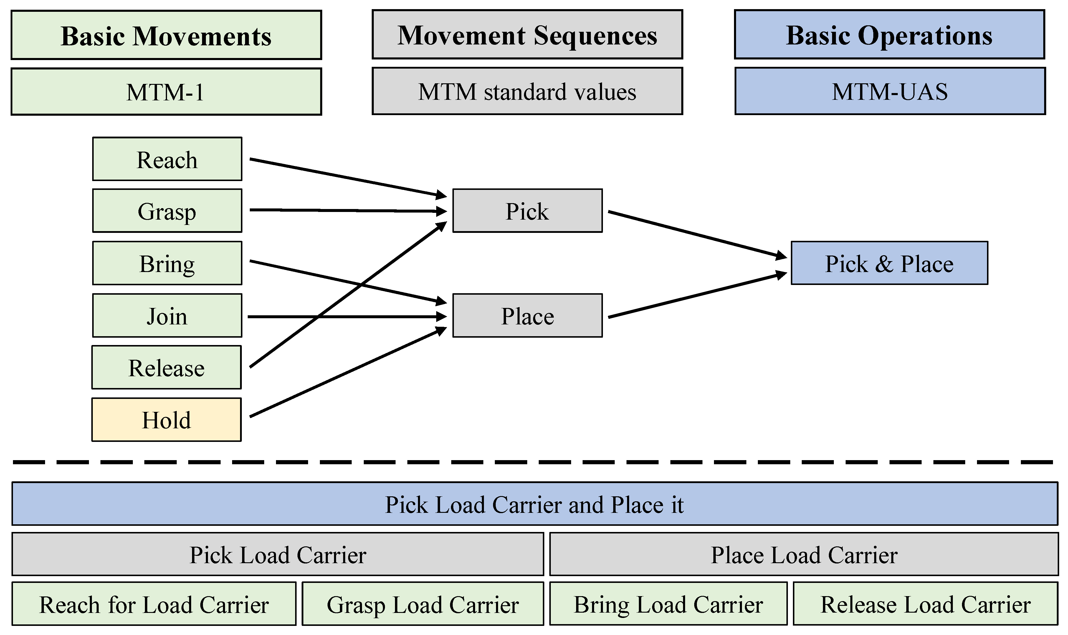
The expert can view those assembly steps in three increasingly granular levels: 1) Basic Operations, 2) Movement Sequences, and 3) Basic Movements. This subdivision is taken from the MTM framework [
33] and is required for precise planning of the assembly sequences as described in
Sec. 4.4. For human-robot interaction in Synchronization or Cooperation, it is sufficient to consider the level of Basic Operations. In Collaboration mode, the level of Basic Movements is required so that the expert can add additional Basic Movements such as “hold" which enables the robot to work as a third hand (see
Figure 2 on the right).
4.3. Assessment Unit
Each step in an assembly sequence requires an evaluation to determine its suitability for a specific human worker or robot. This evaluation relies on skill matrices that outline the unique attributes of each worker (e.g., dominant hand, manual dexterity) and robots (e.g., gripper span, workspace). Additionally, each assembly step is evaluated using a criteria catalogue that encompasses factors such as material properties (e.g., hardness, weight), requirements for basic movements (e.g., required force, possible obstructions), and inspection accessibility.
The method facilitates a comparison between the capabilities of humans and robots by referencing the
skill matrices and evaluating their fit for the task using the
criteria catalogue. For each task, a suitability score, expressed as a percentage, is calculated for both the human and the robot, following the approach outlined by Beumelburg [
27].
A key contribution of this work is the pre-population of the criteria catalog with information described in the previous sections, achieved using a pre-trained classifier model. Any missing or incorrect information is subsequently modified by the expert, who updates the conditions in the model’s tree structure.
The results of the Assessment Unit determine which types of interaction between humans and robots are possible in the subsequent sequence. Assembly steps that can only be carried out by the worker or only by the robot, for example, integrated as fixed points in the assembly priority graph (
Figure 10), around which the rest of the planning is based.
4.4. Planning Unit
Planning is done in three stages: 1) the order of the assembly steps is derived from a
relationship matrix and represented as a
directed graph, 2) tasks are allocated to human and robot, including the decision about the interaction modality, using the results from the Assessment Unit, and 3) multiple dynamic assembly sequence plans are generated considering time, cost and complexity. All stages are illustrated via the toy truck use case shown in
Figure 4.
4.4.1. Task Order of the Assembly Sequence:
Using the hierarchical product structure with its different levels and interrelations as shown in
Figure 6, an assembly
relationship matrix is automatically generated. This matrix displays the pairwise connection relationships between all components of the assembly in a tabular format, incorporating all relevant relations and constraint data obtained from the CAD file. The expert has the option to remove faulty relationships or add restrictions that could not be derived from the data alone. The constraints from the relationship matrix, along with the hierarchical levels of the data model, determine the sequence of assembly steps. The outcome of the first stage of the Planning Unit is a
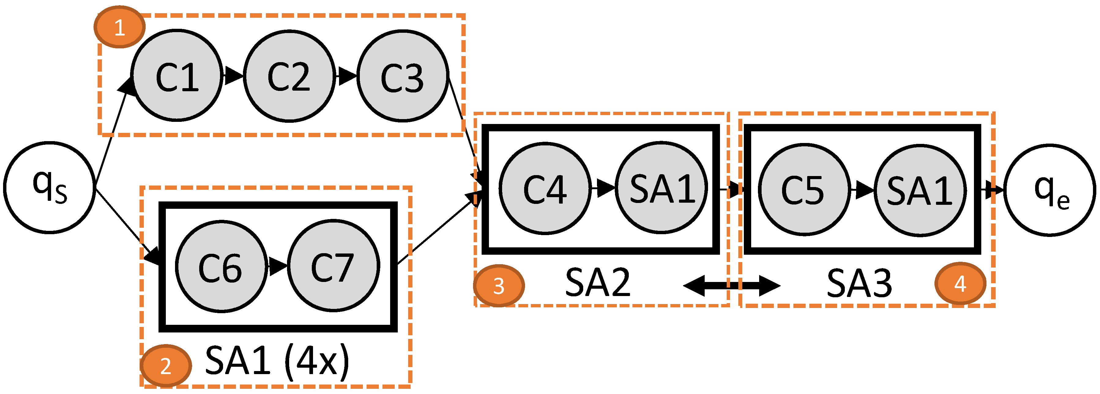
directed graph as shown in
Figure 9.
Node represents the starting point, while node denotes the endpoint of the assembly sequence that culminates in the final product FP. The intermediate nodes correspond to each assembly step within the sequence.
Table 1 outlines the assembly steps for the toy truck example. The initial stage of the directed graph demonstrates a parallel process, comprising assembly steps 1 and 2. Sub-assemblies
SA1 and
SA2 illustrate the sequential progression of these assembly steps.
4.4.2. Task Allocation for Human and Robot:
In the second phase, the results of the Assessment Unit are integrated into the
directed graph by assigning the fixed tasks to either human (blue colored nodes) or robot (green colored nodes) as shown in
Figure 10. The sub-assemblies
SA2 and
SA3, containing possible tasks for a robot (
C4 and C5) and human only tasks (
SA1), allow for multiple types of human-robot interactions. The Planning Unit distinguishes between three interaction modalities: 1) Synchronization, 2) Cooperation, and 3) Collaboration.
In the toy truck use case, the task assignment results in six distinct assembly sequence plans, as illustrated in
Figure 10. During Synchronization and Cooperation mode, the robot places components
C4/C5 into a mounting bracket within the shared workspace. Following this, the human integrates 2x
SA1 with
C4/C5 to create
SA2/SA3. In Synchronization mode, only one agent is permitted in the shared workspace at a time, while in Cooperation mode, both agents can operate simultaneously within the workspace. In Collaboration mode, the robot retrieves components
C4/C5, positions the axle, and holds it steady, allowing the human to concurrently combine 2x
SA1 with
C4/C5 to produce
SA2/SA3.
As shown in
Figure 9, the order of
SA2 and
SA3 can be swapped resulting in three more assembly sequence plans. There are two ASPs per interaction modality yielding the option of adapting the execution of the assembly plan during the actual assembly. This
dynamic property of our system allows to react to unforeseen circumstances during operations, e.g. a short-term bottleneck in material supply.
4.4.3. Determination and Sequencing of the Assembly:
Algorithm 1 which determines the task allocation mentioned above will be presented next. Our approach builds upon the research conducted by Johannsmeier et al. [
5] and incorporates an additional focus on complexity. In addition, we distinguish three distinct interaction modalities: Cooperation, Collaboration, and Synchronization.
For Synchronization and Cooperation mode, human or robot tasks will be allocated to the Basic Operations as described in
Sec. 4.2. In contrast, Collaboration mode divides the Basic Operations into Basic Movements. We use the Basic Movements
reach, grasp, bring, release and
join, based on the work of [
35] and extend them by the
hold which utilizes the robot as a third hand. The expert is able to rearrange and add new Basic Movements as needed. This subdivision allows to form human-robot collaborative team and classify the collaboration mode.
In Synchronization and Cooperation mode, Algorithm 1 processes an input sequence I consisting of a single Basic Operation (). In Collaboration mode, the algorithm handles input sequences of Basic Movements (). The algorithm evaluates the properties of complexity, time, and cost to generate a suitability score, expressed as a percentage. This score indicates how well a human or robot can perform a Basic Operation (for Synchronization and Cooperation) or a Basic Movement (for Collaboration).
The algorithm is detailed as follows. First, the process time (
) for each input sequence
is calculated using:
In this equation
and
represent the human and robot resources, respectively, with their distinct skill metrics. For human resources, the standard times are obtained from MTM-UAS [
34], while for robots, the times are calculated using the modified MTM-UAS approach [
35]. This approach estimates robot times based on the time it takes a human to perform the same task, adjusted by a speed factor
p to account for slower robot speeds. The factor
p varies depending on the type of interaction:
for Synchronization,
for Cooperation, and
for Collaboration. The baseline factor
, used for Collaboration as suggested in [
35], corresponds to a robot speed of approximately 250 mm/s.
|
Algorithm 1 Determination of dedicated tasks for humans or robots, adapted from [17]. |
|
Input sequence where Assignment of human or robot to input
for to n do if then else end if end for
|
Next, the cost factor (
) is computed as follows:
This cost factor, derived from the
skill matrices and
criteria catalogue detailed in
Sec. 4.3, takes into account additional costs such as those for auxiliary devices or specialized grippers. A higher accumulation of these costs results in a higher cost factor for the input
.
Third, the complexity factor is determined using:
This complexity factor considers error probabilities, component handling, and task precision. It includes criteria like whether the robot can handle delicate materials without damaging them and whether the human can apply the required torque to a bolt.
Finally, these three criteria, process time, cost, and complexity, are weighted by an expert using a 3x1 vector . This weighting emphasizes the relative importance of each criterion. The resulting scores for the human () and robot () are expressed as percentages. The resource with the highest score is designated for the input sequence .
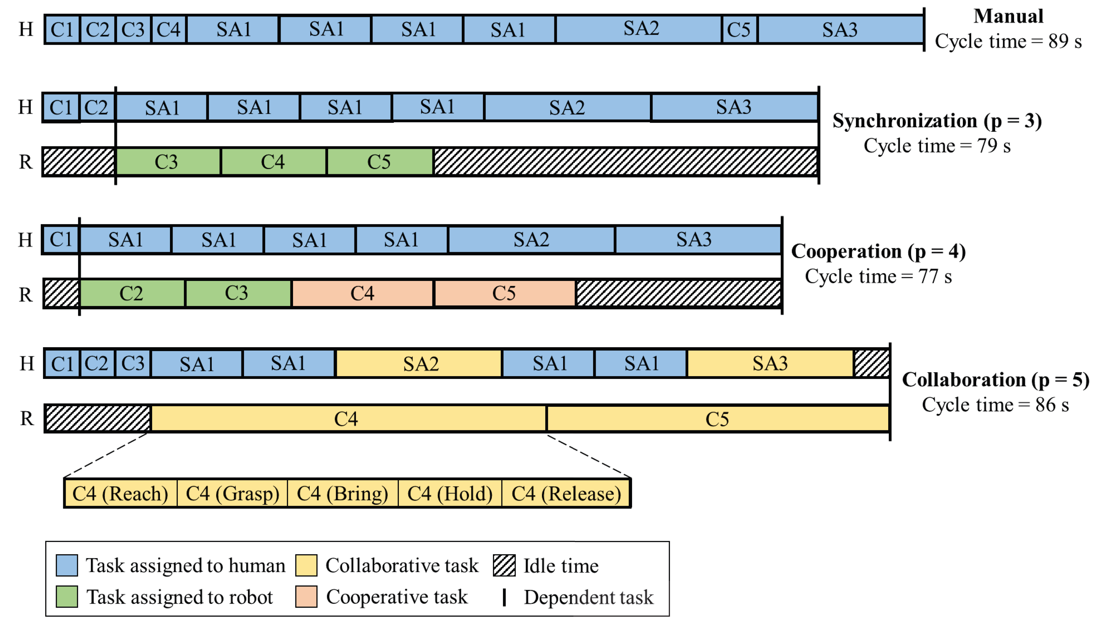
The resulting assembly sequence planning (ASP) for the toy truck assembly is illustrated in
Figure 11 and discussed in detail in
Sec. 5.
4.5. Review Unit
The Review Unit involves an expert in two critical stages of the framework: the Enrichment Unit and the Planning Unit (see
Figure 5). This expert, who is familiar with the product and the abilities of both the worker and the robot, plays a key role in enhancing the process. During the enrichment phase, the expert fills in missing data, addressing challenges related to data heterogeneity and gaps that result from different STEP formats. The data model shown in
Figure 6 provides a structured representation of the component hierarchy which the expert is able to modify if needed. Additionally the assembly step catalogue enables an in-depth representation of the interdependencies and task distribution among the components.
In the Planning Unit, the expert reviews the relationships identified from the assembly relationship matrix and inspects the type of human-robot teamwork for each assembly step. Following the planning phase, the expert performs a plausibility check on the automatically generated assembly sequences. In addition, the expert can express their preference for the relative importance of cost, complexity, and time by adjusting the weighting factor resulting in the generation of alternative assembly sequences.
4.6. Output Layer
The APR framework yields multiple options for the output format of the assembly sequence depending on the required level of detail downstream. Assembly step catalogues for Basic Movements, Movement Sequences, and Basic Operations are possible.
For example, if assembly instructions for the worker are to be generated from the planned sequences, the information on the individual assembly steps can be output as Basic Operations (e.g. “Join axle holder with two screws") and enriched with images extracted from the CAD data. If generic robot commands from the catalogue are to be derived, it is more suitable to output Basic Movements (e.g., “Reach Load Carrier", “Grasp Load Carrier", “Bring Load Carrier").
5. Experimental Results
We evaluate the APR framework in terms of 1) the degree of automation achieved by the Extraction Unit for different CAD formats, and 2) the cycle times of ASPs for three interaction modalities generated by the Planning Unit.
To assess the performance of our Extraction Unit, we determine the degree of automation by calculating the ratio of data processed automatically to the total amount of information available, which includes both automatically extracted data and manually enhanced data provided by the expert. We extracted information from the toy truck use case and compared the results to our initial Extract-Enrich-Plan-Review (EEPR) framework, presented in [
17]. The original EEPR framework exclusively used CAD data in STEP formats AP242, AP214, and AP203 as its information source. The
APR framework presented here additionally includes 2D drawings (DXF) and assembly instructions (PDF/Excel) as information sources.
Table 2 shows the overall results. The
APR framework outperforms the original EEPR by 11% for AP203, 12% for AP214 and 9% for AP242. The highest degree of automation is reached for STEP AP242 (88%). Due to an increase of information richness from AP203 to AP242, the level of automation increases for both frameworks. In situations where only AP203 is accessible, the expert must add more missing data compared to the other formats but our framework remains functional. This shows the adaptability of our holistic framework in accommodating various types of CAD input data.
Additionally, our results focus on the output generated by our Planning Unit. We evaluate three Assembly Sequence Plans (ASPs) featuring different interaction modalities Synchronization, Cooperation, and Collaboration as depicted in
Figure 10. These ASPs are compared to a manual assembly baseline regarding idle time and cycle time. The comparison results are presented in
Figure 11.
Each of the three human-robot assembly plans demonstrates enhanced cycle times relative to manual assembly, primarily because they allow for the simultaneous execution of assembly steps. The parallelizable assembly steps C1 to C3 can be performed either by the robot or the human whereby the robot requires three times the process time (p = 3 in MTM-UAS) for their execution. For the three human-robot assembly sequences, there are different assignments of the assembly steps resulting from the dependencies of the interaction types: In Synchronization mode, steps C1 and C2 are assigned to the human and C3 to the robot. In Cooperation mode, the human performs C1 and the robot C2 and C3. In Collaboration mode, all three steps are assigned to the human.
Cooperation mode is faster than Synchronization mode, although the assembly steps
C4 and
5 take longer (
p = 4). This is due to the effect that in Cooperation mode, humans and robots are allowed to work in the same workspace at the same time and therefore
C5 can be processed simultaneously with
SA2 which is not permitted in Synchronization mode. Collaboration mode is the slowest human-robot ASP resulting from the highest factor
p and the additional Basic Movements (
C4 (Hold) and
C5 (Hold)) the robot performs. These Basic Movements allow the robot to act as a third hand as shown in
Figure 2, right side. Although Collaboration mode is slower compared to the other interaction modalities, the ergonomics for the human improves when a third hand is available.
The incorporation of additional Basic Movements enhances resource utilization, decreasing the robot’s idle time to just 11 seconds, in contrast to 46 seconds in Synchronization mode and 24 seconds in Cooperation mode. It’s important to note that the idle time for the robot in both Synchronization and Cooperation occurs at the beginning and end of the sequence. This allows the robot to engage in other tasks that may not be directly related to truck assembly. For instance, in Synchronization mode, the robot could potentially operate a second truck assembly station.
6. Conclusion and Future Directions
In this work, we introduced a holistic framework designed to streamline the creation of assembly sequence plans for Human-Robot Collaboration. Traditionally, creating these HRC assembly sequences involves a labor-intensive manual process carried out by robotics experts. Our APR framework provides a novel approach by leveraging product and process data such as CAD, DXF, and PDF/Excel files to automatically generate assembly sequences. The framework integrates a product expert at several key stages: for data enrichment, adjustment of weighting parameters related to time, cost, and complexity, and overall review of the generated sequences. We demonstrated and assessed our framework using a toy truck assembly case study. The experimental results highlight the framework’s capability to automate the process across three different CAD file formats and its effectiveness in generating assembly sequences for various human-robot interaction modalities, including synchronization, cooperation, and collaboration.
In future research, we plan to test the framework to more intricate industrial scenarios presented by our industry collaborators, incorporating the
Safety Analysis from our previous work [
40]. We will also compare the cycle times of the generated ASPs with real-time data to evaluate their accuracy. Additionally, we will enhance the pre-population of the criteria catalogue, utilizing a prompt engineering approach to compare and evaluate the results. Our ultimate goal is to leverage multiple assembly sequences during the actual assembly process, allowing for dynamic switching between sequences based on real-time information.
Author Contributions
Conceptualization, Fabian Schirmer and Philipp Kranz; methodology, Fabian Schirmer; software, Fabian Schirmer; validation, Fabian Schirmer and Philipp Kranz; formal analysis, Fabian Schirmer, Philipp Kranz and Chad G. Rose; investigation, Fabian Schirmer and Philipp Kranz; resources, Fabian Schirmer and Philipp Kranz; data curation, Fabian Schirmer; writing—original draft preparation, Fabian Schirmer and Philipp Kranz; writing—review and editing, Chad G. Rose, Jan Schmitt and Tobias Kaupp; visualization, Fabian Schirmer and Philipp Kranz; supervision, Chad G. Rose, Jan Schmitt and Tobias Kaupp; project administration, Tobias Kaupp.; funding acquisition, Jan Schmitt and Tobias Kaupp. All authors have read and agreed to the published version of the manuscript.
Funding
This work was funded by the Bayerische Forschungsstiftung as part of the research project KoPro under grant no. AZ-1512-21.
Data Availability Statement
The software code developed for this work is available upon request from the first author.
Acknowledgments
The authors gratefully acknowledge the financial support by the Bayerische Forschungsstiftung funding the research project KoPro under grant no. AZ-1512-21. In addition, we appreciate the perspectives from our KoPro industry partners Fresenius Medical Care, Wittenstein SE, Uhlmann und Zacher, DE software & control and Universal Robots.
This article is a revised and expanded version of a paper entitled Holistic Assembly Planning Framework for Dynamic Human-Robot Collaboration, which was presented at International Conference on Intelligent Autonomous Systems in Korea, 2023.
Conflicts of Interest
The authors declare that there are no further conflicts of interest.
Abbreviations
The following abbreviations are used in this manuscript:
| DXF |
Data Exchange Format |
| E²APR |
Extract-Enrich-Assess-Plan-Review |
| MTM |
Methods-Time Measurement |
| EEPR |
Extract-Enrich-Plan-Review |
| CAD |
Computer Aided Design |
| ASP |
Assembly Sequence Planning |
| MTM-UAS |
Methods-Time Measurement Universal Analysis System |
| STEP |
Standard for the Exchange of Product model data |
| PDF |
Portable Document Format |
| C |
Component |
| SA |
Sub-assembly |
| FP |
Final product |
References
- World Economic Forum. The Future of Jobs Report 2023. URL: https://www.weforum.org/reports/the-future-of-jobs-report-2023, 2023. accessed: 2024-07-10.
- Organisation for Economic Co-operation and Development. OECD Employment Outlook 2024: The Net-Zero Transition and the Labour Market. URL: https://doi.org/10.1787/ac8b3538-en, 2024. accessed: 2024-07-10.
- Fechter, M. Entwicklung einer automatisierten Methode zur Grobplanung hybrider Montagearbeitsplätze 2022.
- Yoo, S.; Lee, S.; Kim, S.; Hwang, K.H.; Park, J.H.; Kang, N. Integrating deep learning into CAD/CAE system: generative design and evaluation of 3D conceptual wheel. Structural and multidisciplinary optimization 2021, 64, 2725–2747.
- Johannsmeier, L.; Haddadin, S. A hierarchical human-robot interaction-planning framework for task allocation in collaborative industrial assembly processes. IEEE Robotics and Automation Letters 2016, 2, 41–48.
- Faber, M.; Mertens, A.; Schlick, C.M. Cognition-enhanced assembly sequence planning for ergonomic and productive human–robot collaboration in self-optimizing assembly cells. Production Engineering 2017, 11, 145–154.
- Schmitt, J.; Hillenbrand, A.; Kranz, P.; Kaupp, T. Assisted human-robot-interaction for industrial assembly: Application of spatial augmented reality (sar) for collaborative assembly tasks. In Proceedings of the Companion of the 2021 ACM/ieee international conference on human-robot interaction, 2021, pp. 52–56.
- Bauer, W.; Rally, P.; Scholtz, O. Schnelle Ermittlung sinnvoller MRK-Anwendungen. Zeitschrift für wirtschaftlichen Fabrikbetrieb 2018, 113, 554–559.
- Neves, M.; Neto, P. Deep reinforcement learning applied to an assembly sequence planning problem with user preferences. The International Journal of Advanced Manufacturing Technology 2022, 122, 4235–4245.
- Chen, C.; Zhang, H.; Pan, Y.; Li, D. Robot autonomous grasping and assembly skill learning based on deep reinforcement learning. The International Journal of Advanced Manufacturing Technology 2024, 130, 5233–5249.
- Gu, P.; Yan, X. CAD-directed automatic assembly sequence planning. International Journal of Production Research 1995, 33.
- Pane, Y.; Arbo, M.H.; Aertbeliën, E.; Decré, W. A system architecture for cad-based robotic assembly with sensor-based skills. IEEE Transactions on Automation Science and Engineering 2020, 17, 1237–1249.
- Trigui, M.; BenHadj, R.; Aifaoui, N. An interoperability CAD assembly sequence plan approach. The International Journal of Advanced Manufacturing Technology 2015, 79, 1465–1476.
- Neb, A.; Hitzer, J. Automatic generation of assembly graphs based on 3D models and assembly features. Procedia CIRP 2020, 88, 70–75.
- International Organization for Standardization (ISO). Industrial Automation Systems and Integration - Product Data Representation and Exchange - Part 242: Application Protocol: Managed Model-Based 3D Engineering. URL: https://www.iso.org/standard/66654.html, 2020. Accessed: 2022-07-26.
- Schirmer, F.; Kranz, P.; Rose, C.G.; Schmitt, J.; Kaupp, T. Towards Automatic Extraction of Product and Process Data for Human-Robot Collaborative Assembly. In Proceedings of the The 21st International Conference on Advanced Robotics, Abu Dhabi, UAE, 2023.
- Schirmer, F.; Srikanth, V.K.; Kranz, P.; Rose, C.G.; Schmitt, J.; Kaupp, T. Holistic Assembly Planning Framework for Dynamic Human-Robot Collaboration. In Proceedings of the The 18th International Conference on Intelligent Autonomous Systems, Suwon, Korea, 2023.
- Schmidbauer, C. Adaptive task sharing between humans and cobots in assembly processes. PhD thesis, Dissertation, TU Wien. https://doi. org/10.34726/hss, 2022.
- Raatz, A.; Blankemeyer, S.; Recker, T.; Pischke, D.; Nyhuis, P. Task scheduling method for HRC workplaces based on capabilities and execution time assumptions for robots. CIRP Annals 2020, 69, 13–16.
- Berg, J.; Reinhart, G. An integrated planning and programming system for human-robot-cooperation. Procedia CIRP 2017, 63, 95–100.
- Michalos, G.; Spiliotopoulos, J.; Makris, S.; Chryssolouris, G. A method for planning human robot shared tasks. CIRP journal of manufacturing science and technology 2018, 22, 76–90.
- Neb, A.; Schoenhof, R.; Briki, I. Automation potential analysis of assembly processes based on 3D product assembly models in CAD systems. Procedia CIRP 2020, 91, 237–242.
- Prabhu, B.; Biswas, S.; Pande, S. Intelligent system for extraction of product data from CADD models. Computers in Industry 2001, 44, 79–95.
- Zhang, H.; Li, X. Data extraction from DXF file and visual display. In Proceedings of the HCI International 2014-Posters’ Extended Abstracts: International Conference, HCI International 2014, Heraklion, Crete, Greece, June 22-27, 2014. Proceedings, Part I 16. Springer, 2014, pp. 286–291.
- Pan, C.; Smith, S.S.F.; Smith, G.C. Determining interference between parts in CAD STEP files for automatic assembly planning. J. Comput. Inf. Sci. Eng. 2005, 5, 56–62.
- Camelio, J.A.; Hu, S.J.; Marin, S.P. Compliant assembly variation analysis using component geometric covariance. J. Manuf. Sci. Eng. 2004, 126, 355–360.
- Beumelburg, K. Fähigkeitsorientierte Montageablaufplanung in der direkten Mensch-Roboter-Kooperation; 2005.
- Schröter, D. Entwicklung einer methodik zur planung von arbeitssystemen in mensch-roboter-kooperation; Stuttgart: Fraunhofer Verlag, 2018.
- Ranz, F.; Hummel, V.; Sihn, W. Capability-based task allocation in human-robot collaboration. Procedia Manufacturing 2017, 9, 182–189.
- Casalino, A.; Zanchettin, A.M.; Piroddi, L.; Rocco, P. Optimal scheduling of human–robot collaborative assembly operations with time petri nets. IEEE Transactions on Automation Science and Engineering 2019, 18, 70–84.
- Bänziger, T.; Kunz, A.; Wegener, K. Optimizing human–robot task allocation using a simulation tool based on standardized work descriptions. Journal of Intelligent Manufacturing 2020, 31, 1635–1648.
- Weckenborg, C.; Kieckhäfer, K.; Müller, C.; Grunewald, M.; Spengler, T.S. Balancing of assembly lines with collaborative robots. Business Research 2020, 13, 93–132.
- Bokranz, R.; Landau, K. Handbuch industrial engineering. Produktivitätsmanagement mit MTM 2012, 2, 2.
- Karger, D.W.; Bayha, F.H. Engineered work measurement: the principles, techniques, and data of methods-time measurement background and foundations of work measurement and methods-time measurement, plus other related material; Industrial Press Inc., 1987.
- Weßkamp, V.; Seckelmann, T.; Barthelmey, A.; Kaiser, M.; Lemmerz, K.; Glogowski, P.; Kuhlenkötter, B.; Deuse, J. Development of a sociotechnical planning system for human-robot interaction in assembly systems focusing on small and medium-sized enterprises. Procedia CIRP 2019, 81, 1284–1289.
- Komenda, T.; Brandstötter, M.; Schlund, S. A comparison of and critical review on cycle time estimation methods for human-robot work systems. Procedia CIRP 2021, 104, 1119–1124.
- Pratt, M.J.; et al. Introduction to ISO 10303—the STEP standard for product data exchange. Journal of Computing and Information Science in Engineering 2001, 1, 102–103.
- Ou, L.M.; Xu, X. Relationship matrix based automatic assembly sequence generation from a CAD model. Computer-Aided Design 2013, 45, 1053–1067.
- Halperin, D.; Latombe, J.C.; Wilson, R.H. A general framework for assembly planning: The motion space approach. In Proceedings of the Proceedings of the fourteenth annual symposium on Computational geometry, 1998, pp. 9–18.
- Schirmer, F.; Kranz, P.; Manjunath, M.; Raja, J.J.; Rose, C.G.; Kaupp, T.; Daun, M. Towards a Conceptual Safety Planning Framework for Human-Robot Collaboration 2023.
|
Disclaimer/Publisher’s Note: The statements, opinions and data contained in all publications are solely those of the individual author(s) and contributor(s) and not of MDPI and/or the editor(s). MDPI and/or the editor(s) disclaim responsibility for any injury to people or property resulting from any ideas, methods, instructions or products referred to in the content. |
© 2024 by the authors. Licensee MDPI, Basel, Switzerland. This article is an open access article distributed under the terms and conditions of the Creative Commons Attribution (CC BY) license (http://creativecommons.org/licenses/by/4.0/).

