1. Introduction
In recent years, the development of Wearable Exoskeletons has experienced significant growth due to the potential of this technology in a great variety of applications. Indeed, these devices can be employed for assistance [
1], rehabilitation [
2], and augmentation [
3]. Several research efforts for enhancing wearable exoskeletons focus on the mechanical [
4] and control [
5] solutions to improve the performances in terms of physical Human-Robot Interaction (pHRI), achieving increasingly safe and ergonomic devices that guarantee an efficient modulation of the interaction forces according to the application.
High-performance actuators (i.e., the combination of motors and power transmission mechanisms) play an essential role in enhancing pHRI [
6,
7]. Therefore, the exoskeletons’ actuation modules are required to be efficient while guaranteeing low costs and weights to not compromise the price and usability of the device [
8]. Among the numerous possibilities for actuating wearable exoskeletons, high torque-density electric motors coupled with suitable gearing systems represent a valuable and frequent solution [
9]. In the literature, multiple implementations of Geared Electric-motor-driven Exoskeletons can be found, such as [
10,
11,
12,
13], exhibiting a wide spectrum of reducers’ designs and transmission ratios as a function of the applications’ requirements.
Despite the unquestionable worth of the current ’geared’ exoskeletons, the use of transmission mechanisms involves issues such as the increase in complexity, weight, and cost of the wearable device. Since the reduction in weight and cost is a desirable feature for exoskeletons, some works report the use of 3D-printed components for the development of light wearable robots [
14,
15]. However, given the recent advancements in Additive Manufacturing (AM), 3D printed components also draw attention as a potential option for developing efficient, lightweight, and cost-effective reducers capable of enhancing pHRI in robotic exoskeletons, thus facing the problem of increasing costs and weights due to reduction gearboxes.
Several studies assess the value of using polymeric materials for building gears. For example, [
16] reports an investigation about materials for lightweight reduction gears to reduce robot weight by using composite materials and resins. Weight reduction tends to decrease stiffness, resulting in a drop in the speed and precision performance. The authors evaluate the applicability of replacing metal parts with plastic materials made using fused deposition modeling 3D printer. In other works, such as [
17,
18,
19], the authors evaluate the influence of multiple printing parameters such as printing nozzle temperature, speed, printing bed temperature, and infill percentage, furthermore assessing fatigue life and failure types of 3D-printed gears made of polylactic acid (PLA). In [
20], the authors carry out experimental determinations to generate new conclusions regarding the ability of 3D-printed gears to be integrated into mechanisms without lubrication, considering factors such as sliding speed, material hardness, surface finish, and surface geometry. Moreover, some studies focus on evaluating dimensional accuracy, form errors, and surface quality regarding FFF (Fused Filament Fabrication) [
21,
22]
However, to the authors’ knowledge, only a few and recent studies explore the possibility of exploiting 3D-printed geared transmission in wearable devices [
23,
24,
25]. Other works in the literature present scattered implementations with isolated experimental investigations about 3D-printed reducers, thus not allowing a comparison of different gearbox designs and reduction ratios. For example, in [
26] and [
27], the authors present 3D printed actuators, but they limit the study to low reduction ratios (from 1:7.5 to 1:15), only considering the classic planetary design and its compound variation. Other studies focus on 3D printed cycloidal reducers, as in [
23,
28,
29], where the authors report design details and experimental results focusing on a single low-ratio (1:11 and 1:30) cycloidal reducers.
Notwithstanding the merits of the mentioned works, the literature lacks a more extensive and comprehensive evaluation of 3D-printed reducers. Therefore, the goal of this work is to investigate and compare multiple 3D-printed reducers to examine the possibility of using such mechanisms in wearable exoskeletons and enhance proper pHRI.
This study presents a fairly wide-ranging comparison of 3D printed reducers, exposing light-weight and low-cost implementations of three different transmission solutions, i.e. single and double-stage cycloidal reducers, planetary compound transmissions, and the series combination of cycloidal and planetary gearboxes in a double-stage reducer. These designs are examined inspecting the respective performances for two reduction ratios, i.e., 1:30 and 1:80, that are plausible for rehabilitative devices, as well as for exoskeletons conceived for assistance and augmentation. Overall, eight reducers are compared. Their 3D models (STL files) are available on request to the authors, together with the list of off-the-shelf components (bearings, screws, and nuts) exploited for the assembly.
In summary, the main contributions of this paper are:
The design and realization of eight different 3D-printed reduction gearboxes, for a comprehensive evaluation of their features.
The comparison of multiple transmission designs and reduction ratios that, to the authors’ knowledge, have not been examined before in the field of 3D-printed actuators (i.e., compact double-stage cycloidal reducers, high transmission ratios above 1:50, and the series combination of cycloidal and planetary gearboxes).
An experimental evaluation of multiple performance indexes (e.g. Backdrive torque, friction, gear play, stiffness, etc.) for each reducer that concurrently allows for a comprehensive assessment of several transmission designs implementing different reduction ratios.
The remainder of this paper is organized as follows: in section Background a brief presentation of the reduction designs exploited in this work is reported, then the section Materials and Methods reports a brief presentation of the reduction designs exploited in this work, followed by more detailed descriptions of the presented 3D-printed mechanisms. Then, in the Experimental Evaluation section, the experimental setup and metrics are described, also exposing the procedure of the performed tests. The section Results and Discussion reports some evaluative considerations about the results of the experimental analysis, discussing the different features of the investigated reduction mechanisms, with a focus also on the current limitations of the proposed approach and the expected future works. Finally, in the Conclusions part a summary of the proposed work is reported, together with the most relevant inferences.
2. Background
2.1. Transmissions Architectures
2.1.1. Single-Stage Cycloidal Reducer
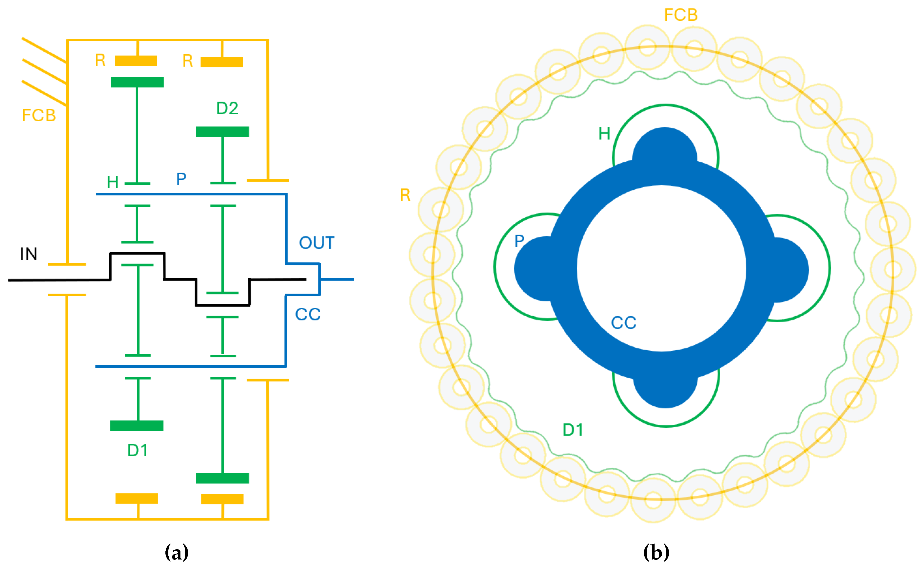
The working principle of the cycloidal reducers involves four main components: an eccentric shaft that represents the input motion, a cycloid disk mounted on the eccentric shaft that engages with the pins (or rollers) that compose the fixed cycloidal base, and a set of output-pins fixed to the carrier, that represents the transmission’s output. The reduction mechanisms take the name from the profile of the disk, which indeed can be traced back to a
cycloid [
30]. A simplified illustration is reported in
Figure 1.
The rotation of the eccentric shaft causes the roto-translation of the cycloid disk, which engages with the cycloid base’s rollers (in this case, bearings). The rotation of the disk generates the movement of the output pins in the holes in the cycloid disc. This bore-pin coupling allows the output shaft to rotate non-eccentrically. The output shaft’s rotational speed can be deduced by the gear ratio
where
is the number of lobes of the cycloidal disk and
is the number of rollers connected to the fixed cycloidal base. The cycloidal base can be composed of pins or rollers (usually bearings or bushings); the main differences between these two architectures are studied in [
29]. Two cycloid disks have been used (each engaging with a different set of rollers), with a difference in phase of 180°, ensuring that the unbalanced forces compensate each other, resulting in smoother operation at high speeds and reduced vibrations. The two sets of rollers that engage with the disks are identical.
The cycloidal systems allow us to obtain high reduction ratios simply with a difference of only one tooth between the number of rollers and the number of lobes on the disk. These reducers also ensure lower frictions and smoother contact forces, with respect to the classic geared wheels, between the disk and the cycloidal base, which is composed of bearings as rollers (pin-wheel configuration), allowing for more efficient contact dynamics between disk and base (creeping contacts are prevented).
2.1.2. Double-Stage Cycloidal Reducer
As can be deduced from the previous explanation of the cycloidal reducer’s architecture (especially considering
Figure 1b)), for high reduction ratios, the cycloidal architecture demands a high number of rollers. These rollers have to be distributed on a sufficiently large circumference, increasing the reducer’s width. To avoid this, the design proposed in [
31] can be employed. This architecture is illustrated in
Figure 2a.
This design allows for high reduction ratios while maintaining reasonable encumbrance since the reduction ratio is computed as
where
is the number of lobes of the disk of the first cycloidal stage, while
is the number of rollers that compose the moving cycloidal base, which is the base of the second cycloidal stage.
However, this design maintains the presence of a carrier, which inevitably leads to the presence of screws (used to increase the resistance of the pins) and bearings, which are mounted in the holes of the cycloidal disks to improve the contact dynamics between output pins and disk’s holes.
To avoid these problems, some works (e.g. [
32,
33]) exploit an alternative version of a double-stage cycloidal drive, with a compact disk (composed of two joint disks) that avoids the presence of a carrier, allowing for a significant decrease of weight and cost. This architecture’s reduction ratio is computed as
where
is the number of lobes of the disk of the first cycloidal stage,
is the number of rollers that compose the moving cycloidal base (that is the base of the second cycloidal stage), and
is the number of lobes of the second stage cycloidal disk.
2.1.3. Cycloidal-Planetary (CP) Series Reducer
Planetary transmissions have four main components: the sun gear, planetary gears, the carrier, and the ring gear, which is the only internally toothed component of the reducer. This kind of mechanism comprehends several modes of operation, determined by which parts are fixed and which parts rotate. Typically, only two of the three sets of gears will rotate. Concerning the implementations presented in this work, the planetary configuration consists of a fixed ring gear, a rotating sun gear as the input, and a rotating carrier (connected to the planet gears) as the output.
The gear ratio in a planetary transmission is determined by the difference in the number of teeth on the ring gear and the sun gear. Given the following equations, that represent the sun-planet and planet-ring interaction respectively, the overall gear ratio of a planetary gearbox can be deduced in the generic case that involves the rotation of all the gears.
where
N stands for the number of teeth,
represents the rotating velocity, and the subscripts
s,
p,
r, and
c stands respectively for
sun,
planet,
ring, and
carrier. Concerning the planetary gearsets presented in this work, we consider the relation between the number of teeth:
Moreover, as mentioned previously, the ring gear is fixed in the designed gearboxes, so
. Finally, the transmission ratio considered in the rest of the paper for the single-stage planetary transmissions is
Usually, simple epicyclic planetary stages used with a stationary ring gear are employed for implementing gear ratios that vary from 1:3 to 1:9.
The
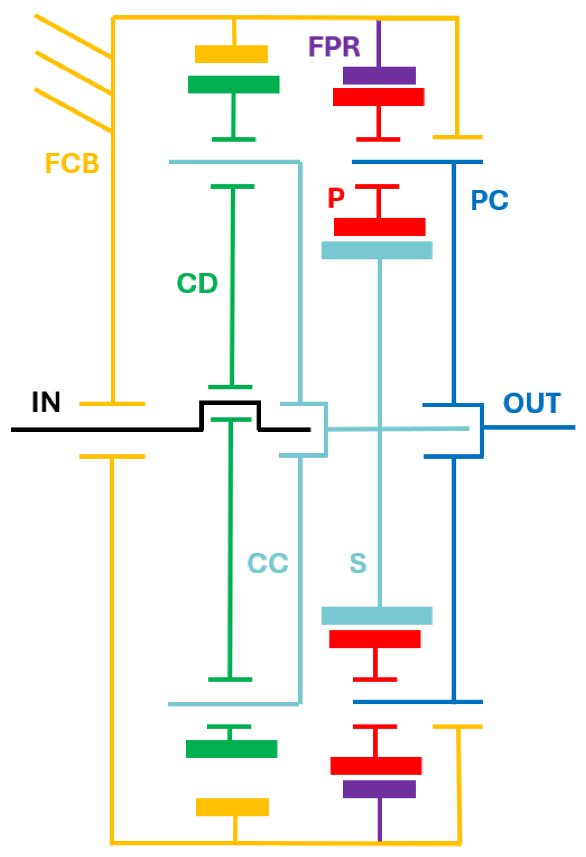
CP reducers are designed as a series combination of a cycloidal and a planetary reducer. The output of the cycloidal stage (the carrier) coincides with the input of the subsequent planetary stage, the sun. This combination allows the exploitation of the two combined architectures at their most fit ratios: the cycloidal reducers with lower ratios allow for fair radial encumbrances, and the planetary stages, as mentioned above, are bound to reduction ratios up to 1:9 [
34]. The resulting gear ratio can be deduced by combining (
1) and (
7), thus obtaining the Equation (
8).
In
Figure 3 a schematic representation of the Cycloidal-Planetary reducer is reported.
2.1.4. Compound Planetary Reducer
Given the limitations of the standard planetary gearbox reduction ratios for the high reduction ratios chosen for this study, the design explained in [
34] represents a suitable and compact architecture. In that work, the author presents the analysis and design of epicyclic gear arrangements to achieve higher gear ratios.
Due to the possibility of implementing high ratios, compound stepped planetary gear drives (CSPG) are very suitable for applications with size restrictions, e.g., gear reducers for actuators in wearable robots. The design of the reducers presented in the following sections is shown in
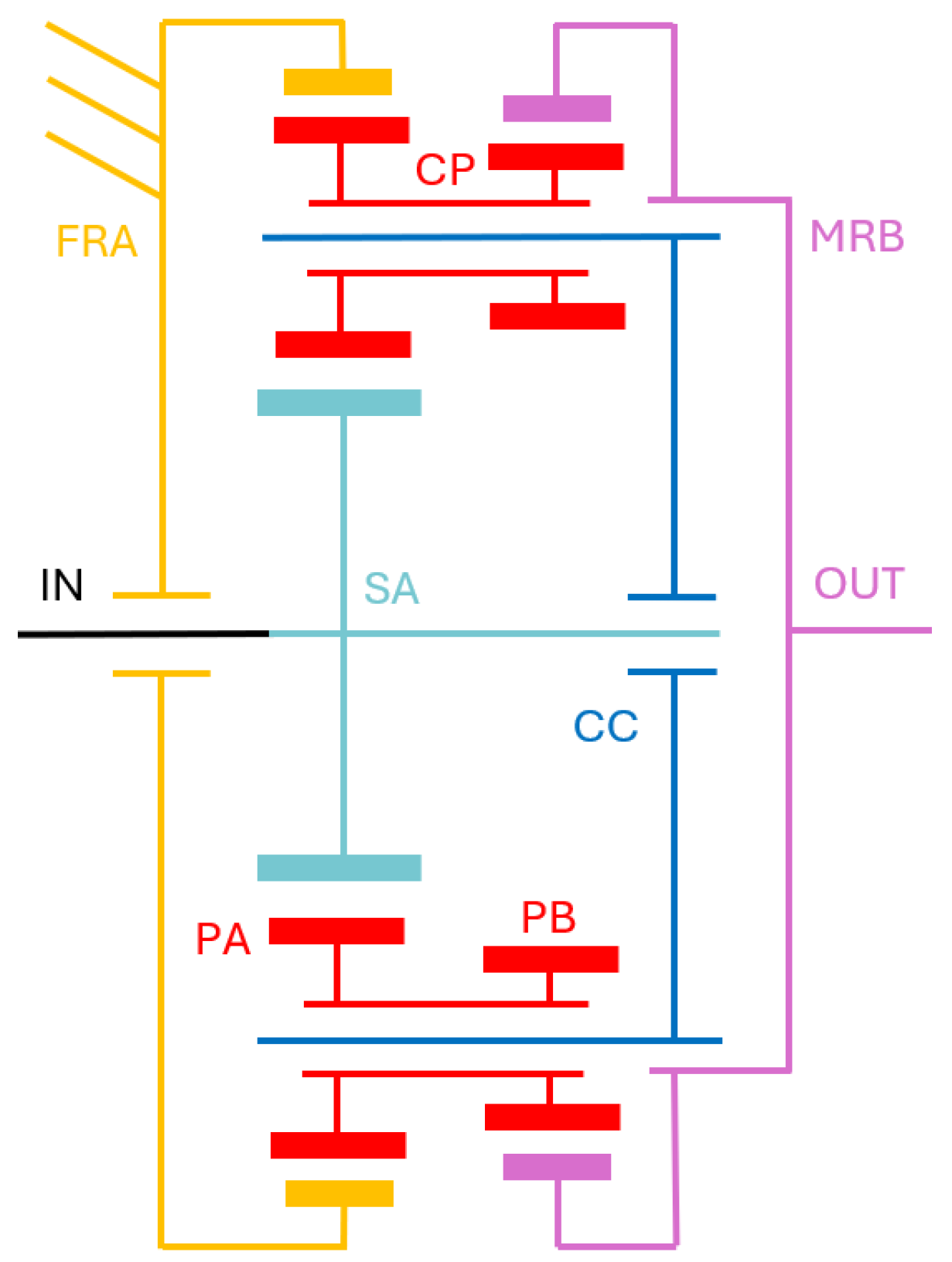
Figure 4 and was selected among those proposed in [
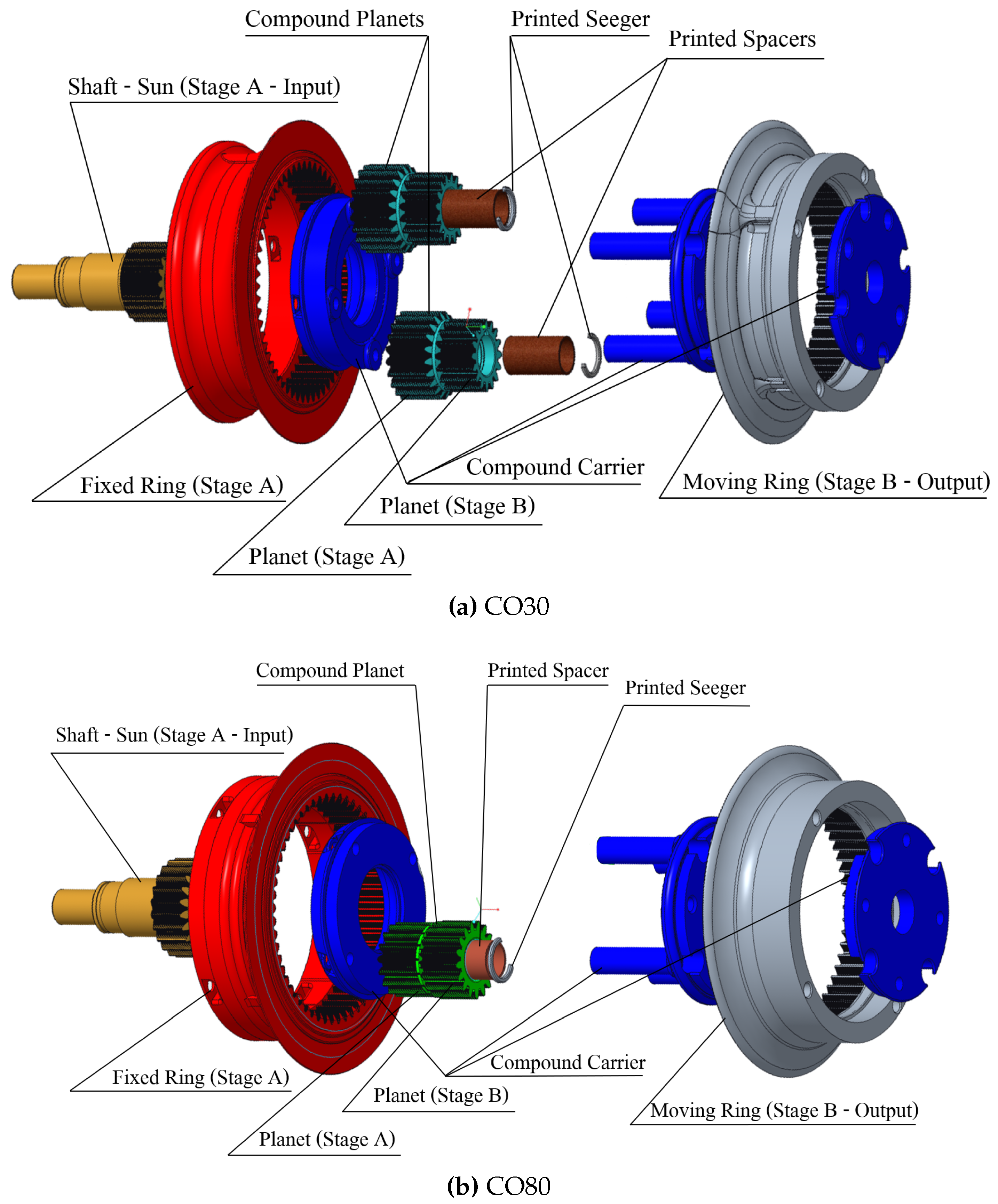
34]. This reducer is a combination of two stages (addressed as A and B) of planetary reducers. Differently from the classic planetary architecture, two ring gears compose the compound transmission: the first one (Stage A) is fixed to the stator of the motor whereas the second ring gear (Stage B) is the output of the reducer. The input shaft moves the sun of Stage A. The sun of the Stage B is not included. The compound planets are composed of two different base planets rigidly connected to form a single component. The reduction ratio of this reducer can be computed according to the equation
where
denotes the number of teeth of a general gear and the subscripts are composed of
(where these numbers stand for sun, planet, and ring respectively) and
(where these letters stand for the first and second planetary stages, respectively).
3. Materials and Methods
3.1. Design Assumptions and Constraints
The first design constraint is the transmission ratio, whose selected values are 1:30 and 1:80. These values have been selected because lower ratios would demand high-torque expensive motors, which is in contrast with the goal of cost-effective and wearable actuators. Instead, higher ratios may produce excessive reflected inertia and higher back-drive torques [
13], which is undesirable in pHRI. For setting encumbrances’ constraints, we considered as references the 3D-printed reducers from valuable works such as [
26,
28,
29] (with maximum reduction of ratio 1:15). The diameter and height constraints for designing the target reducers were selected decreasing lightly the measures that the authors report for the reducers from the mentioned studies. The goal was to maintain reasonable dimensions while aiming for higher reduction ratios, therefore the maximum diameter and height have been set respectively to 100 mm and 55 mm.
3.2. Proposed Reducers
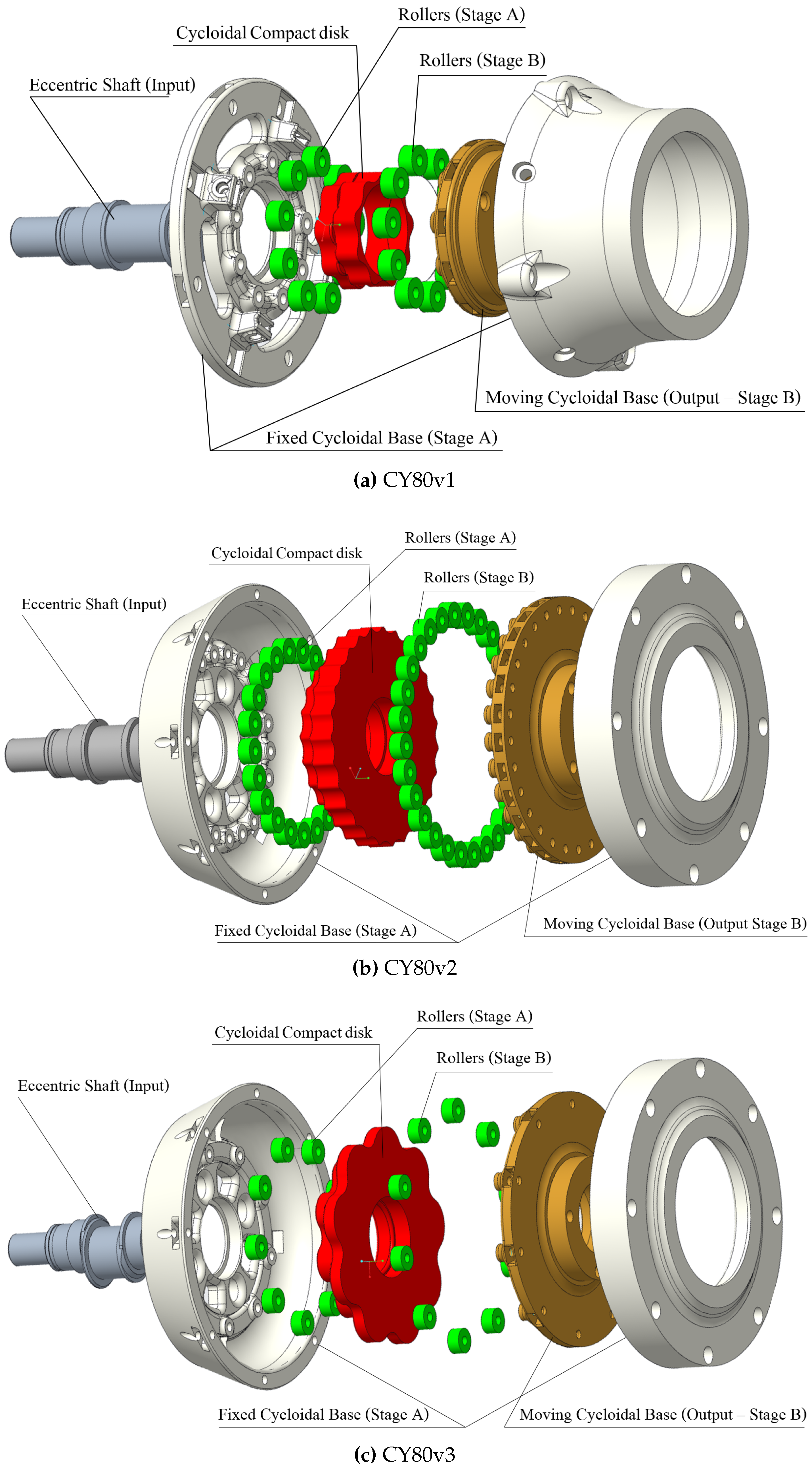
This section presents the structures of the proposed reducers. In the following, the proposed reducers will be addressed with acronyms that refer to the gearbox designs: CY stands for cycloidal, CO symbolizes the compound planetary design, and CP stands for cycloidal-planetary series. For example, CY30 refers to the cycloidal reducer with a ratio of 1:30, while CO80 stands for the compound planetary gearbox with a reduction ratio equal to 1:80. Regarding the CY80 reducers, since three versions have been explored for assessing the characteristics of this design, each of these reducers will be referred to using CY80vx, where .
3.2.1. CY30
For the design of this reducer and of the other reducers including cycloidal stages, the choice of the rollers has been fundamental, since it affects the other dimensions once the reduction ratio has been set. A low roller’s radius allows for reduced encumbrances, but it may reduce the torque transmission capability of the reducer.
On the other hand, large rollers may lead to better torque performances. However, given the target ratio (1:30) and the constraint on the maximum diameter (100mm), an excessively high roller’s diameter would not fit the design goal. Moreover, larger rollers (bearings) would cause an excessive increase in the cost and weight of the reducer. The chosen roller radius of 4 mm represents a valid compromise: it entails acceptable reducer dimensions, weight, and costs. Moreover, its internal diameter of 3mm allows fixing the rollers to the cycloidal base through M3 screws, which is important for guaranteeing a stable and resistant connection between the base and the rollers.
Once the rollers’ dimensions had been set, the minimum possible cycloidal base radius was computed so that the rollers would not interfere with each other’s motion. The choice of the cycloidal base radius is correlated also with the eccentricity. Indeed, an excessively small base radius would limit the eccentricity. Indeed, given a certain roller dimension and cycloidal base radius, a rise of the eccentricity value would cause the cycloidal disk to have an increasingly discontinuous lateral surface, therefore causing a severely irregular output motion. The same reasoning about the parameters’ values has been used for the design of the other cycloidal stages presented in the following and will not be repeated
Table 1 displays the chosen values for the design parameters of the
CY30 reducer.
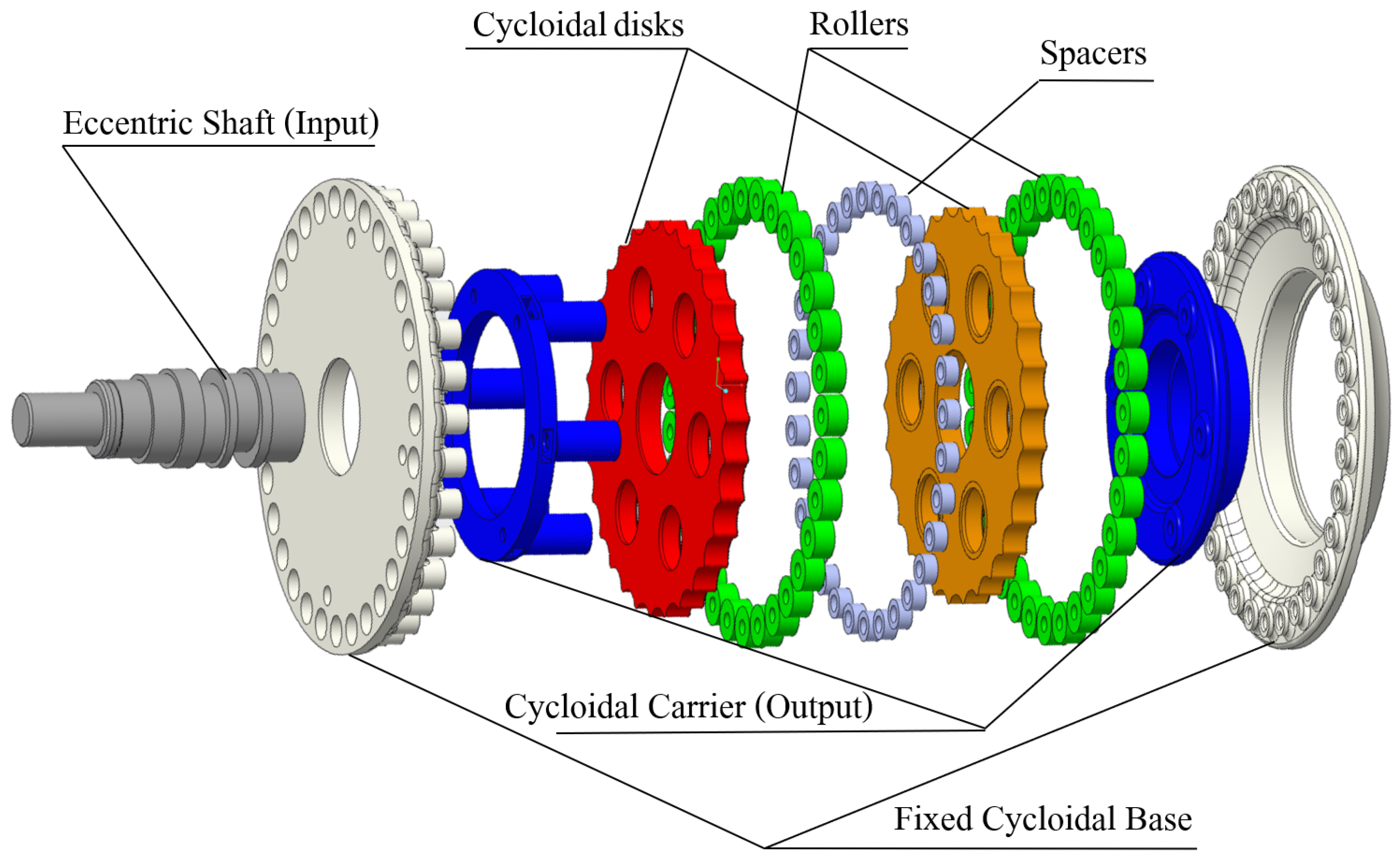
Figure 5 represents a cad model of the exploded view of the
CY30 reducer, without including bearings (exception made for the rollers) and screws. The input shaft has two opposing eccentric sections, that are coupled through bearings to the disks, one out of phase of 180° with respect to the other. These disks engage with two sets of rollers, separated by a row of printed spacers. Both the spacers and the rollers are connected to the cycloidal base (the lower and upper white parts) through screws and nuts. Also, screws of different lengths are used to reinforce the pins that compose the cycloidal carrier.
3.2.2. CY80
According to the reduction ratio Formula (
3), the chosen
CY80 architecture allows for multiple combinations regarding the number of rollers of the fixed and moving cycloidal bases. Besides the number of rollers, eccentricity is the other parameter that influences directly the dimensions of the reducer.
Since this reduction mechanism is not widespread (to the authors’ knowledge, it was never implemented in a 3D-printed version), we decided to design and test different alternatives for the number of rollers and eccentricity. This contributes to this work’s goal of exploring different architectures for 3D-printed reducers. The design parameters reported in the
Table 2 describe the three presented design arrangements:
- -
CY80v1 implements the solution with the minimum dimensions. Both the numbers of rollers at the fixed and moving cycloidal bases are the minimum allowed for reaching the 1:80 ratio. Also, the value of the eccentricity is limited to 1 mm.
- -
CY80v2 implements the version with the maximum number of rollers that allows respecting the maximum diameter constraint (considering the rollers with a 4 mm radius), combined with an eccentricity that is set to 0.8mm.
- -
CY80v3 implements the reducer version with the minimum number of rollers (the same as the first version). However, the dimension has been pushed almost to the maximum limit. Indeed, as can be noted by comparing the values from
Table 2, the diameters of the cycloidal bases are the same, thus the employment of the same number of rollers of
CY80v1 allows for a pronounced eccentricity (2.5 mm).
Variants with both a high number of rollers and high eccentricity have been avoided in order not to exceed the encumbrance constraints.
The cad models from
Figure 6 represent the exploded views of the three CY80 reducers. The input shafts present a single eccentric section which is connected to the double-stage compact disk through two ball bearings that are not shown in the reported pictures. The separate stages of rollers are connected to the respective base (fixed or moving). The upper part of the Fixed Cycloidal Base encloses the entire reducer and works as a support also for the Moving Base, which is connected to it through another bearing.
3.2.3. CP30 and CP80
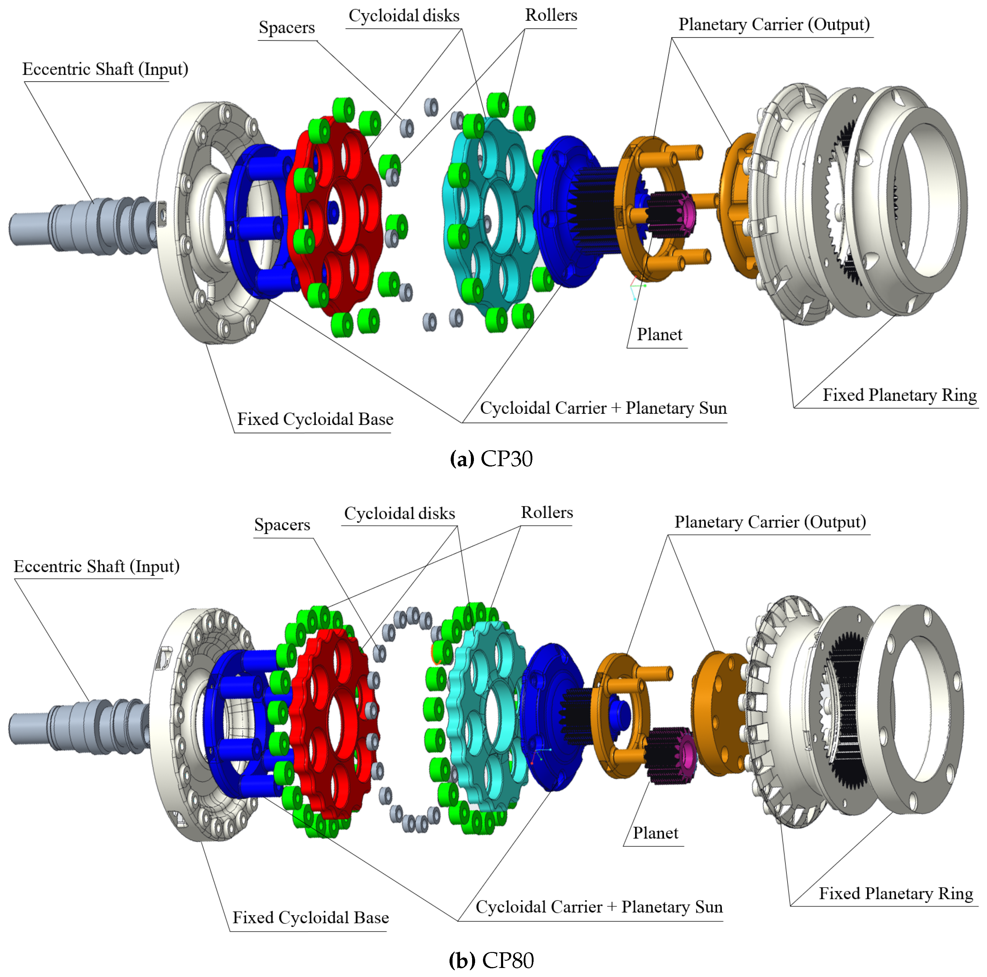
For the design of the Cycloidal-Planetary reducers, the series of these architectures has led to joint considerations about the dimensional compatibility for a correct combination. First of all, the respective reduction ratios to be combined have been chosen to exploit the two combined architectures at their most fit reduction rates.
Since classical single-stage planetary reducers are employed to implement low transmission ratios [
35], we decided to realize 1:3 and 1:4 ratios, respectively for the 1:30 and the 1:80 total target. This leads to the selection of 1:10 and 1:20 transmission ratios for the respective cycloidal stages. Since these values are lower than the 1:30 that is presented above, through this design radial encumbrances are reduced in both the
CP reducers with respect to the
CY30.
However, it is clear from the basic structure of a cycloidal reducer that the presence of the carrier sets an inferior limit to the reducer’s diameter. A valid compromise was found to be the cycloidal stage with a 35 mm fixed cycloidal base radius and a 21 mm Carrier radius. As can be noted from
Table 3, these values have been utilized for both the
CP reducers, as well as other design parameters.
Once the dimensions of the cycloidal stage have been set, we designed the planetary stages to keep their encumbrance smaller than the cycloidal one. The number of teeth of the external ring (together with the teeth module) determines the maximum diameter of the planetary stage. We decided to employ gears with a module of 1 mm, a valuable compromise between excessively small teeth, with resulting modest resistance and more difficulties for a correct print of the gear profile, and higher modules that produce unacceptable encumbrance. The equations below report the relations between teeth module, radial encumbrance, and teeth height.
where
represents the height of the teeth (function of the module
m) and
is the primitive circumference of the gear, which gives an approximate idea of the gear’s encumbrance, and which is computed as the product of the module and the number of teeth
. Once the correct ring’s teeth number has been set, the rest of the parameters can be deduced from the Equation (
7).
Table 3 reports the whole set of parameters for the CP30 and CP80 reducers.
3.2.4. CO30 and CO80
From Equation (
9), a target reduction ratio can be obtained with multiple combinations of teeth numbers. At the same time, compound reducers do not have the encumbrance constraints due to the cycloidal stage that limited our target dimensions in the CP reducers. Therefore, we could increase the module to 1.2 mm, where it was 1 mm in CP reducers. Teeth module increase still leaves room for teeth number selection, and we decided to set the minimum number of teeth for the gears (both sun and planets) of the two stages to 16, to have the possibility for the carrier’s pins to be designed with a sufficiently large diameter. This must be large enough to allow each planet to contain two bearings for a proper assembly on the carrier pin. Given this premise, we managed to implement the minimum teeth choices that met the mentioned constraints for both the
CO30 and
CO80. As can be noticed from the
Table 4, the two presented designs have equal carrier radius and essentially almost identical dimensions.
The cad models reported in
Figure 8 represent the exploded views of the CO reducers. The sun of the first stage (i.e., the input) engages with the Stage A Planet inside the Stage A Fixed Ring. Given that the compound planets consist of two different gears rigidly connected, the sun’s motion induces the common carrier to rotate, and thus the Stage B planets engage with the Stage B Ring, which is the output of the reducer.
3.3. Materials, Printers, and Off-the-Shelf Components
For the development of the presented reducers, PLA has been employed since it combines reasonably low costs and valuable mechanical properties [
21]. The employed printers are the Ultimaker S7 Pro Bundle and the Ultimaker S3-Extended, using Ultimaker Cura as a slicer. The parts that were not produced through 3D printing are exclusively the bearings, screws, and nuts. Indeed, besides the mentioned components, spacers and Seeger rings have been produced through printing procedures.
The lists of the necessary non-printed components for each reducer are reported in the tables from
Appendix A. Besides the bearings, which are clearly essentials in the reducers’ structures, off-the-shelf components (especially the screws) have been fundamental for strengthening some highly loaded structural components such as the carrier pins in all the exploited designs, and linking the rollers to the cycloidal bases.
3.4. Evaluation Metrics
To evaluate the features of the proposed reducers and to compare different reduction ratios implemented through multiple designs, the following metrics have been taken into consideration for designing the experimental protocols described in the next section:
-
Speed Regularity
-
: the parameter that describes the oscillating deviation between the actual output speed of a reducer (given a certain motor’s speed) and its expected value, computed as the product of the motor’s speed and the reduction ratio, according to the following formula:
where
R is the regularity (expressed as a percentage value),
is the reducer’s speed,
i is the transmission ratio, and
is the motor’s velocity.
It is important to evaluate the regularity of a reducer to be able to assess how precise and stable the actuator’s capacity to maintain a certain velocity can be.
-
Friction
: the amount of torque that the motor has to deliver to cope with the static (Coulomb) and dynamic (viscous) forces that oppose the reducer’s motion. The knowledge of the actuator’s internal friction is fundamental for implementing friction compensation, which is fundamental to enhancing the transparency in pHRI.
-
Gear Play
: the range of motion of the reducer’s output (in the locked-input condition) that can be observed without sensing resisting torques from the actuator. Lower gear play corresponds to a more precise motion of the actuator.
-
Gear Stiffness
: the relation between the torque applied to the output of the reducer (in the locked-input condition) and the consequent motion monitored at the output itself. This parameter has preferred values depending on the application of the actuator itself. For example, a stiffer actuator increases precision in trajectory following control, while a more compliant system can be preferred for a smoother pHRI.
-
Backdrive Torque
: the static torque that has to be applied to the output link of the reducer to initiate the motor’s motion. This feature is essential in wearable devices that should function without obstructing the user’s voluntary motions.
-
Size, Weight, and Cost
: Ultimaker PLA (Polylactic acid) has been used for the development of the reducers’ components, so that the transmissions’ masses, encumbrances, and prices are mainly affected by the employed bearings and screws, depending on the quantities. Wearable devices should be as lightweight and compact as possible to enhance acceptance and usability for the users. Moreover, guaranteeing cost-effective actuators (maintaining valuable performances) is an important goal to spread the utilization of assistive wearable devices both in work-related environments and everyday-life applications.
4. Experimental Assessment
This section first describes two configurations of the experimental setup employed to identify the investigated features. Then, the experimental procedures for each test are presented.
4.1. Experimental Setup
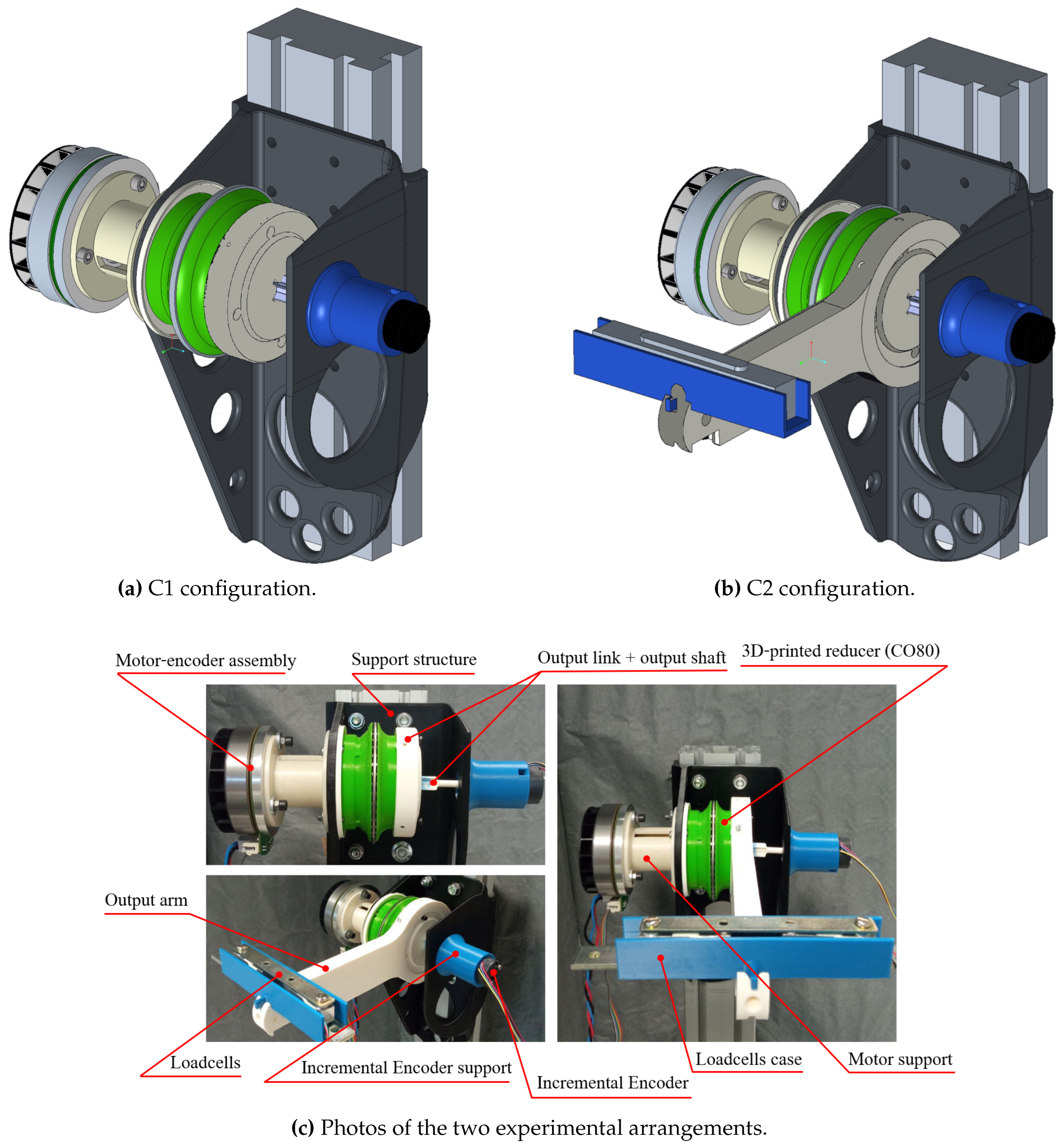
Figure 9 presents the setup with photos and CAD models of the two possible experimental arrangements, addressed as
C1 and
C2, reported respectively in
Figure 9a and
Figure 9b.
Figure 9c highlights the main hardware components.
The experimental setup is composed of the brushless motor (EC 90 flat, 360 W, 90 mm, Maxon) with an integrated 2-channel encoder (MILE 512–6400 CPT, Maxon) coupled to the reducer’s input through the motor support. The reducer’s output is coupled to the incremental magnetic encoder (H2 Series, Phoenix America) through the encoder support, the output link, and the output shaft. These components are fixed to a vertical beam with a 3D-printed support structure.
The motor-encoder assembly is controlled by the three-phase brushless DC motor driver (STEVAL-SPIN3201, STMicroelectronics). Instead, the magnetic encoder and the two loadcells (CZL635, Phidgets Inc.), placed in a case on the output arm, are connected to the STM32 Nucleo-144 development board (NUCLEO-F767ZI, STMicroelectronics). Both the boards are connected to the central unit (Intel NUC 11 Pro, i7-1165G7) running Windows 11 and Simulink (MATLAB, Mathworks Inc.), where a PID (Discrete PID Controller Simulink block) implements a speed control and a Kalman Filter estimates the motor speed.
4.2. Experimental Protocols and Metrics Examination
The experimental apparatus allows testing the reducers and thus comparing their characteristics through the evaluation of their performances employing multiple procedures. Before testing the reducers’ performances, we identified the motor’s torque constant as well as the motor’s static and viscous internal friction. To identify the torque constant, we made the motor reach a constant velocity regimen while exerting constant torques for moving known loads. We determined the motor’s internal friction by driving the motor to follow multiple low-frequency speed sine references. The registered current data have been used for implementing the motor’s friction compensation.
4.2.1. Speed Regularity
This test required the use of the
C1 experimental setup. To evaluate the speed regularity, the PID speed control has been used for controlling the motor velocity, setting a sequence of step references from 20
to 120
, with 20
increments. The same test have been repeated three times for each reducer with positive speed references, and three times with negative velocities. For each speed step, the mean oscillation of the reducers’ output velocity around the regiment value is monitored and divided by the actual target speed, according to the Equation (
12).
4.2.2. Friction
This test required the
C1 experimental setup. Transmission friction was estimated by imposing motor speed sinusoidal references in the range ± 100
with frequency of 0.005
. The
Sine Wave Simulink block has been used for generating the reference signal. For this procedure, we took as references [
28,
36]. Each reference signal has been followed by the motor for at least three different periods, i.e. more than 6 minutes. The same experiment was repeated three times for each reducer, Velocity and current were registered during this procedure. Subsequently, the following friction model has been fit for each reducer:
where
is the friction torque,
is the static Coulomb friction component,
is the dynamic viscous factor, and
is the motor velocity. The current information has been reported to torque data by multiplying them by the motor’s current constant.
4.2.3. Gear Play
This test required the C2 experimental setup. Gearing play was estimated by measuring the maximum possible output motion (variation of the output magnetic encoder data) without motion of the motor axis, which was detected from the motor-integrated encoder data. This experiment was carried out by manually moving the output arm in different positions over a full output turn without applying significant torques to the output arm. This latter condition is necessary to avoid the joint stiffness contributing to the resulting output shaft motion, thus leading to an incorrect gear play estimation. For each reducer, these tests were carried out during three different experimental sessions.
4.2.4. Gear Stiffness
This test required the C2 experimental setup. Transmission stiffness was estimated by manually applying a series of loads to the loadcells assembly, mounted on the arm (with a 0.2 m lever) while monitoring the current loadcells force signal. This was repeated six times for each reducer, around different output positions with 60° increments, to account for position dependence. We sampled the applied torque values by multiples of 5, then we evaluated a possible linear fit that produces a valuable estimated reducer’s stiffness, i.e., the torque-displacement ratio.
4.2.5. Backdrive Torque
This test required the C2 experimental setup. To get information about the back-drivability of the full actuator, i.e. the motor connected with each of the reducers, we exploited the combination of arm and loadcells. The motor was initially set to a position such that the output arm was horizontal, to have a reference for adjusting the torque term due to the weight of the arm and the loadcells depending on the analyzed angular position. Gradually increasing forces were applied manually to the load cells until the motor started moving. This procedure is repeated at least 5 times during each of the three different experimental sessions.
The value of the backdrive torque is then estimated detecting the motor movement and evaluating the corresponding applied torque. To sample the torque value corresponding to the necessary moment to start the back-drive motion we selected 0.175°, which is twice the encoder resolution, as the angular displacement threshold to detect the motor motion onset. The respective torque value was identified for each experiment.
As mentioned before, the considered torque is the sum of the effects of the forces manually applied on the loadcells and the weight of the 3D-printed arm and the loadcells themselves, adjusting the subsequent torque based on the output angle with respect to the horizontal position.
4.2.6. Encumbrance, Weight and Cost
Regarding the size of the reducers, their maximum height and diameter have been obtained from the model and verified by measurements. To evaluate the cost, the sum of the prices of the non-printed components (bearings, screws, and nuts) has been added to the cost of the printed parts. The value of the PLA elements has been estimated based on their weights by considering the price of the employed material as the sum of the material cost, the amortization of the printer estimated on the printer’s whole life, and the energy supply cost.
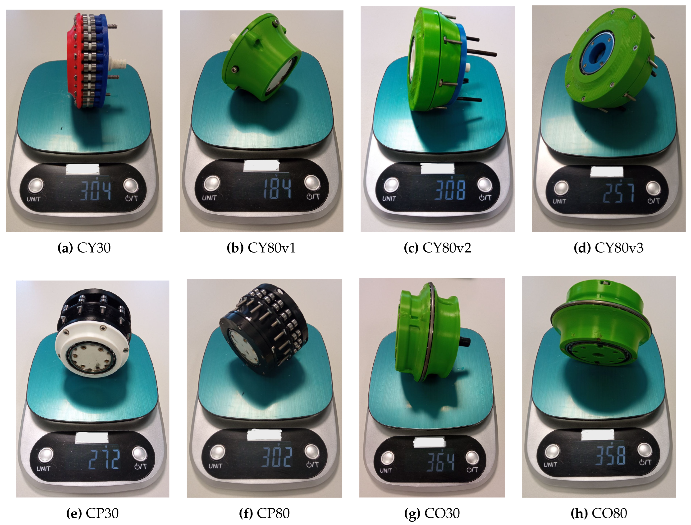
The prices of the non-printed components (reported from the web page of the same dealer) have been considered based on the quantities that are necessary for each reducer: indeed, for example, when buying a certain quantity of the same bearing the cost per unit decreases. Therefore, the cost of each reducer depends on the number of units of the same components that constitute it. The weights of the reducers have been simply measured through a scale.
5. Results and Discussion
The experimental data gathered through the previously mentioned procedures allowed for a fair comparison of the reducers’ performances and characteristics in relation to the described metrics.
5.1. Speed Regularity
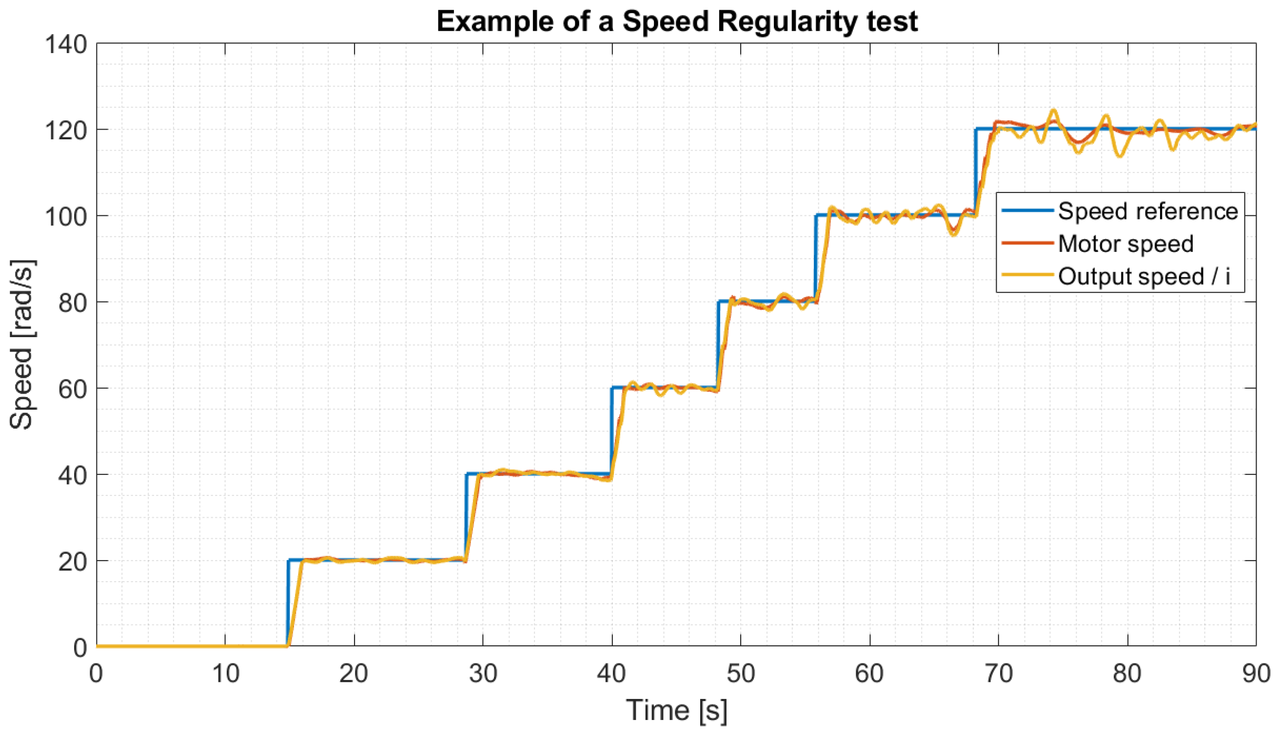
In
Figure 10 one of the sequences of speed steps performed by the motor-reducers system is represented by reporting the reference signal and both the motor and the output velocities.
The latter has been multiplied for the specific ratio to clarify the comparison with the motor velocity. It has to be noted that, for the regularity evaluations, the data from the velocity transient phases have been ignored. The
Table 5 reports the reducers’ regularity values for all the evaluated velocities. The best values for each velocity step are presented in bold characters. The mean and standard deviation values for each reducer are reported in the first column of
Table 6.
By comparing the regularity values for the different monitored motor velocities, we showed that the regularity does not degrade with the evaluated speed. Thus the reducers’ performance does not worsen for high speeds, which is a good feature for transmission.
It is clear from
Table 5 that for most of the considered motor speed values the best regularity has been achieved by the
CO30 reducer. Valuable performances have also been verified for the
CY30 reducer. Regarding the other presented gearboxes, from
Table 7 it can be noted that the worst results were registered for the
CY80v1 and
CY80v3, which showed remarkably higher oscillations during the speed regularity tests. Concerning the contribution of the cycloidal profiles’ parameters, the measured regularities suggest that an increment in the eccentricity leads to an increment of the speed fluctuations’ amplitude. Indeed, the
CY80v3 (which implements the higher eccentricity among the cycloidal stages reported in this work) presents the highest oscillations for all the tested velocities. The regularity difference between the
CY80v1 and
CY80v2 can be attributed to the disparity of the number of lobes. A higher number of rollers in both the cycloidal stages guarantees a more continuous movement of the cycloidal disk, which during the rotation maintains contact with more rollers. For a similar reason (however, considering the standard cycloidal gearbox implemented in
CY30) we can justify the high regularity of the 1:30 cycloidal reducer. Lastly, the
CP reducers exhibit reasonable regularities, considering both the 1:30 and 1:80 reducers. Indeed, these reducers have been designed with a quite low eccentricity, that, combined with the planetary stage, produce acceptably regular reducers.
To sum up, the proposed CY80 architecture presents the higher velocity deviations, while the CP80 can be considered the most regular among the 1:80 reducers.
It should be noted that features such as regularity are strongly influenced by the lack of reproducibility and tolerance limitations linked to the process of fused filament fabrication. These characteristics depend on multiple settings and factors, such as the printer, the slicer, and the printing environment.
5.2. Friction
During the experimental session carried out to estimate speed regularity, we recorded motor current, which was used to estimate the torque needed to move the actuator through the motor torque constant.
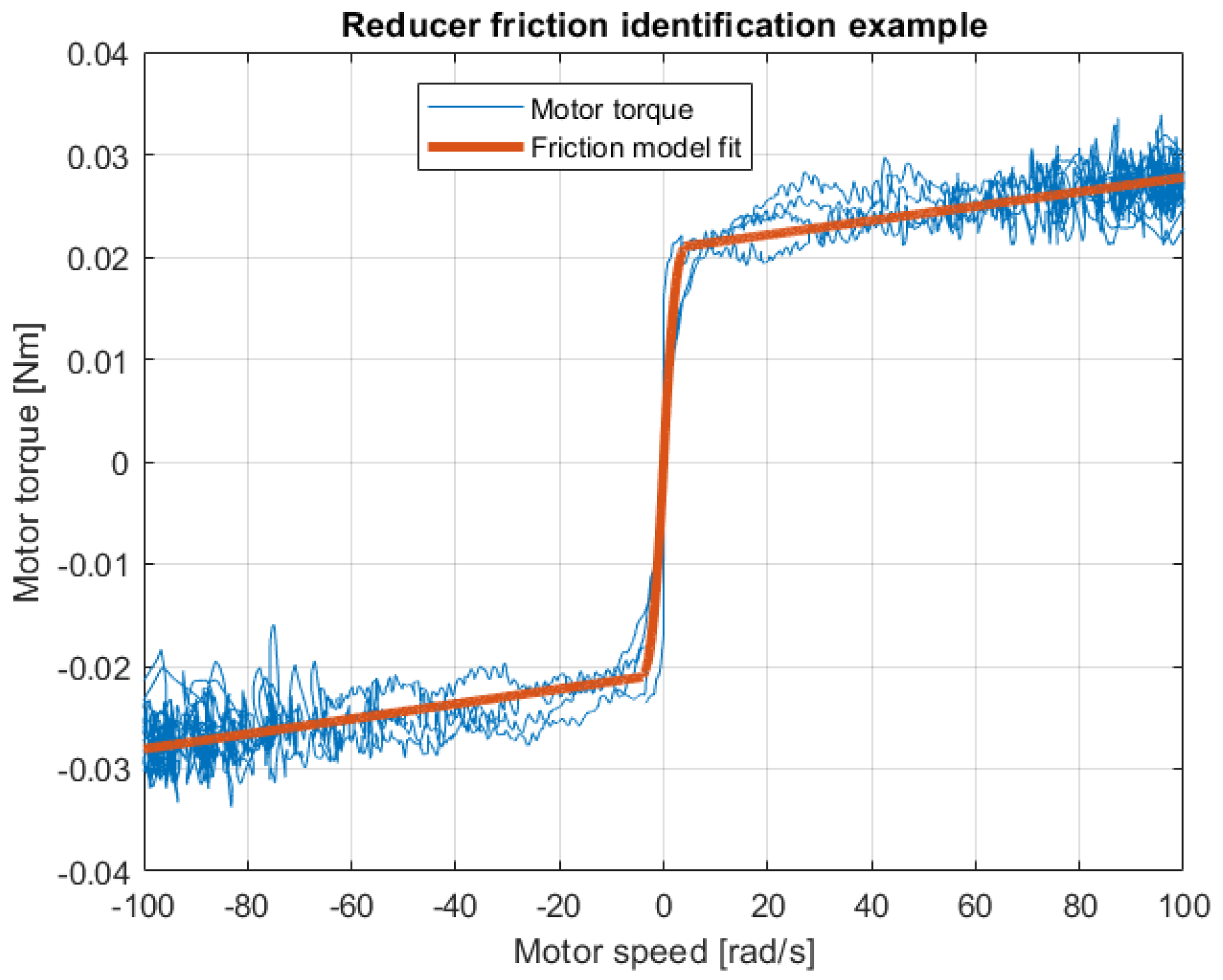
The sampled motor torque and speed were used for the identification of the adopted friction model by computing the static and viscous friction parameters of Equation (
13). An example of this process is reported in
Figure 11. In
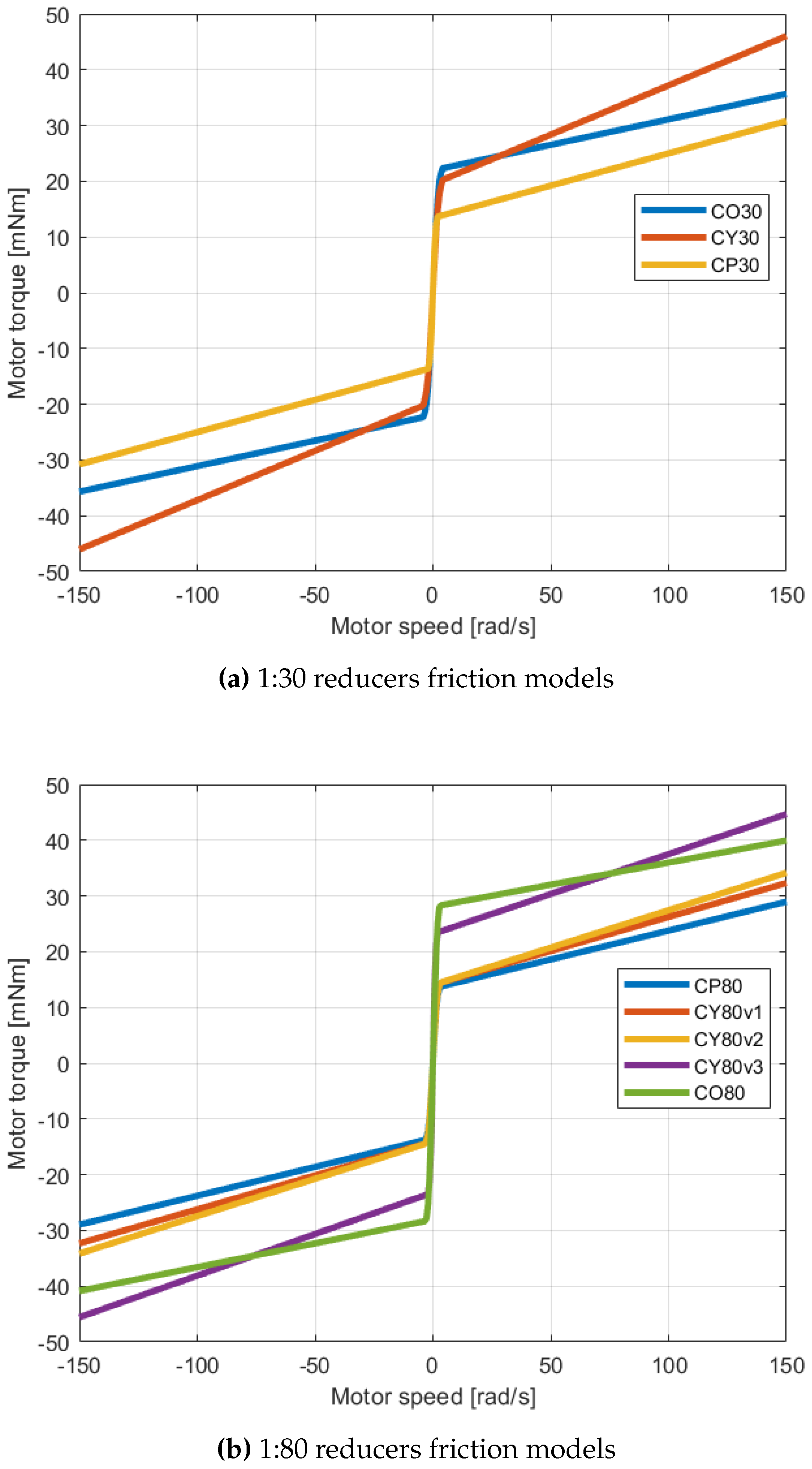
Figure 12 the resulting friction models for all the reducers are reported. We presented separately the results regarding the two different ratios (1:30 in
Figure 12a and 1:80 in
Figure 12b) to avoid ambiguous superimposition of the functions.
The mean and standard deviation values for both the static and viscous friction factors of the reducers are reported in
Table 6. The best values are marked in bold text.
Based on the plots in
Figure 12 and the values reported in
Table 6 it can be noted that the architectures that incorporate a cycloidal stage (
CP and
CY reducers) display lower static frictions, unfortunately exhibiting higher viscous components at the same time. The opposite statements describe the
CO models. The highest and lowest registered static friction torques are respectively the ones reported for the
CO80 and
CP30 reducers. Concerning the viscous component, the lowest (and thus the best) results were achieved by the
CO80 reducers, while the highest value is the one monitored for the
CY30, confirming that the cycloidal reducers show higher dynamic frictions that become more prevailing with the increment of employed rollers. Nonetheless, we can state that all the presented reducers demonstrated valuable performances regarding their internal friction factors.
Considering possible applications of the proposed reducers in wearable exoskeletons, different requirements can be identified depending on the device’s purposes. For example, in a device whose joints require frequent speed inversions a low static friction is needed. On the other hand, some applications may require high velocities at the joint, thus demanding transmissions with low viscous frictions. According to the devices’ requirements, the employed friction model can be used to check the torque required by the motor to compensate for resisting forces.
5.3. Gear Play
Gear play was estimated according to the procedure reported in
Section 4.2.3. The mean and standard deviation of measured play are reported in the
Table 7, marking the best value in bold text. As it can be stated by evaluating the gear play results reported in
Table 7, the
CY reducers display the highest range of angular motion. Concerning the
CY30 reducer, both the carrier’s pins’ dimensions and the disks’ surfaces affect the gear play. Regarding the
CY80 reducers, the dimensions of the disk with respect to the cycloidal bases’ rollers influence the gear play along with the contact combination between the two parts that compose the double compact disk.
The impact of the 3D-printing procedure’s constraint on the dimensional tolerances, together with the repeatability issues, stands out notably for the cycloidal architectures, indeed the best gear play results are those presented for the CO reducers. Despite underperforming CO reducers, the CP models display valuable gear plays when compared with off-the-shelf planetary gearboxes with comparable transmission ratios.
5.4. Gear Stiffness
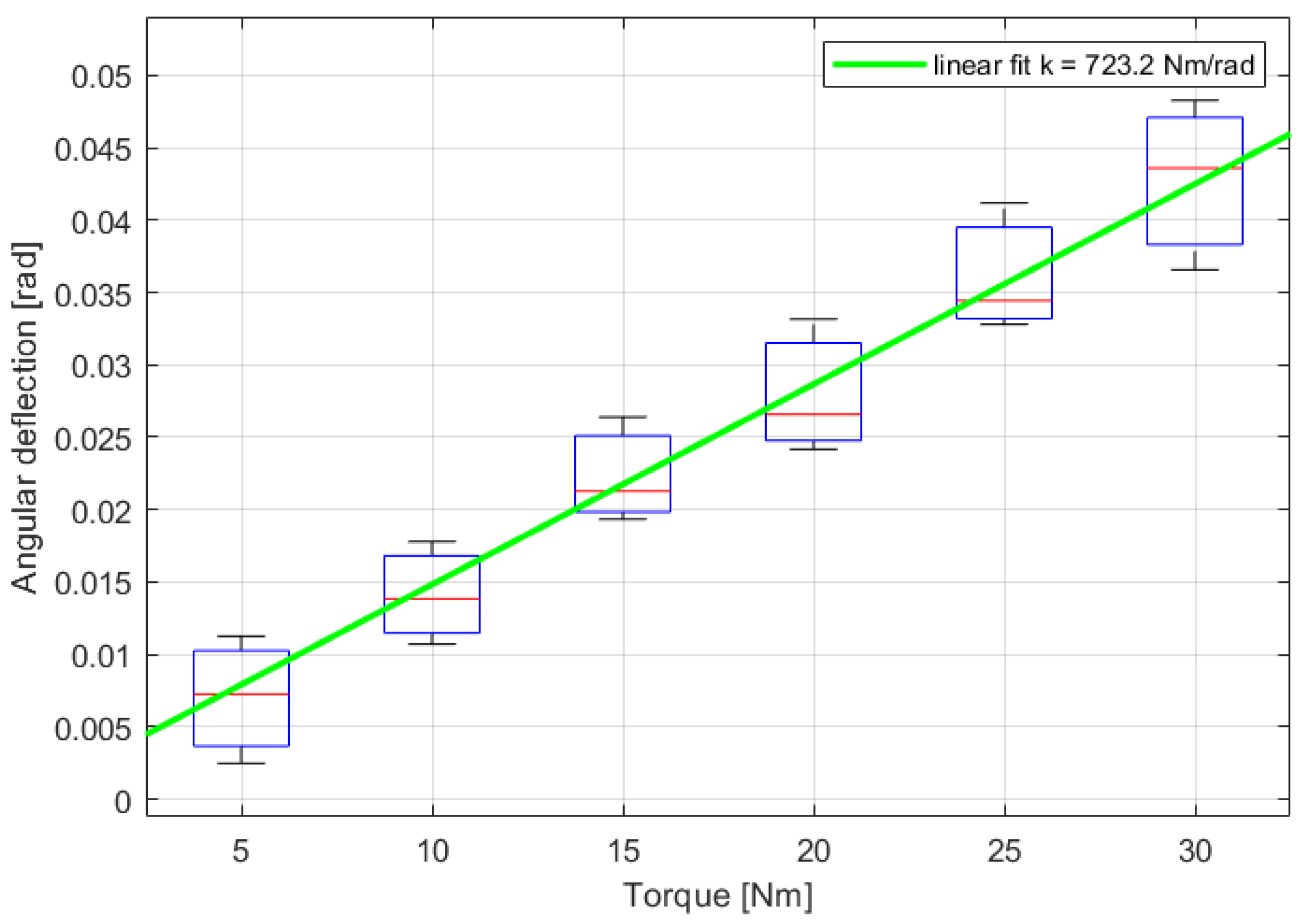
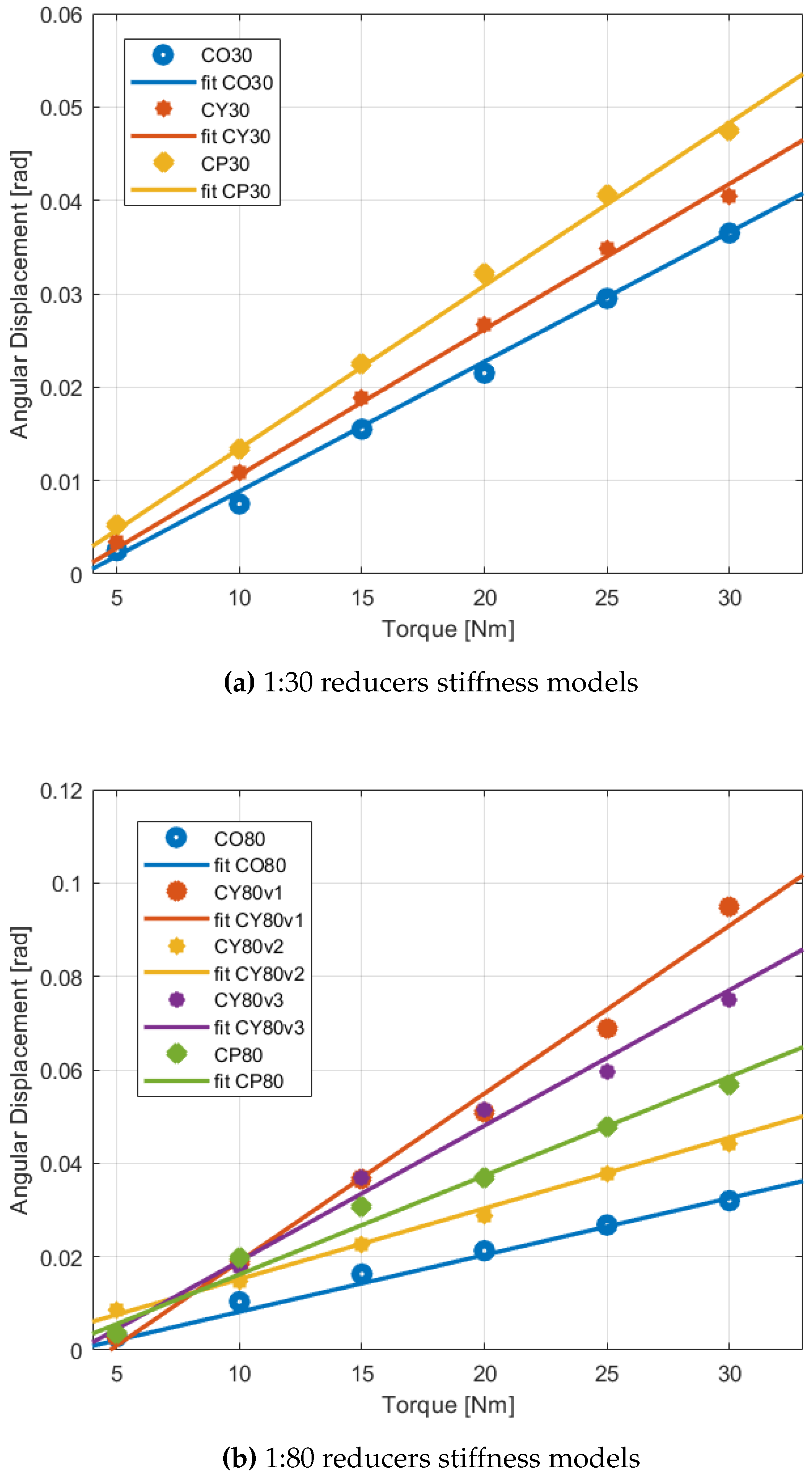
The linear fitting of the motor torque-angular displacement profiles allowed the estimation of each gear stiffness. An example (the case of the
CO30 reducer) of the linear fit of experimental stiffness data is presented in
Figure 13. The overall plot of the torque-displacement mean values for each sampled torque and linear fits for the reducers are reported in
Figure 14.
The stiffness mean values and standard variations are computed for each reducer by employing the resulting stiffness for each of the analyzed starting positions. Considering the values reported in the summary
Table 7, the highest stiffness estimations are those related to the
CO reducers. As mentioned before (during the evaluation of gear play, friction, and regularity) the presence of the cycloidal stage influences also the reducers’ stiffness, given the nature of the contact between the rollers and the 3D-printed disks. Moreover, with respect to the
CP models, the
CO reducers present teeth with a module equal to 1.2 mm, which appears to confer greater stiffness. The estimated stiffnesses are 4-10 times smaller than commercial off-the-shelf planetary gearboxes. However, these values are still neglectable in the control of wearable exoskeletons.
Anyhow, besides the CO and CP models, the CY30 and CY80v2 cycloidal reducers emerge for their significant stiffness. Regarding the two remaining models, that is to say, the CY80v1 and CY80v3, given their reduced number of rollers, the disk-roller contact is restricted to a low number of points, thus a restricted area. This feature easily induces the printed disks to buckle when exposed to high torques, however not necessarily compromising the reducers’ performances.
5.5. Backdrive Torque
The mean values and standard deviation of the computed back-drive torques (measured at the reducers’ output) are reported in the
Table 7. The best value, that is to say, the one regarding the
CP30 reducers, is marked in bold text. As can be stated by the presented results, all the 1:30 reducers present extremely valuable back-drive torques, such that these transmissions could be certainly used in wearable devices for assistance or augmentation.
On the contrary, the CO80, CY80v1, and CY80v2 are non-back-driveable. Thus their use is restricted to cases where the user’s motions should not deviate from the robot trajectory, such as in several rehabilitative devices, or in complex designs that include force sensors at the human-robot interfaces. The CY80v3 is the only CY80 model that can be back-driven. Even if its necessary torque is quite high, this result was achieved by combining the minimum number of rollers solution with a high eccentricity. The rollers’ combination implemented in CY80v2 would have resulted in backdriveable if associated with a high eccentricity, but - as discussed previously - this solution would have led to an unacceptable increase of the reducer’s width.
The CP architecture demonstrated the lowest back drive torque, both for the 1:30 and 1:80 reducers. The CP80 reducer draws attention to being the only 1:80 model to be reasonably backdriveable. Moreover, it exhibits a back drive torque so low that it results comparable with the ones obtained from the other 1:30 transmissions.
5.6. Encumbrance, Weight, and Cost
Table 8 reports the empirical data regarding encumbrances (in the form of maximum heights and widths), weights, and costs for all the presented reducers. The best values are marked in bold text. Regarding the maximum width, the best reducers are the
CP30 and
CP80. It should be noted that also the
CO reducers could have had a decreased width, but their radial encumbrance is constrained by the axial bearing (as can be noted by the photos from
Figure 15 and the cad models
Figure 8).
Considering the reducers’ heights, notwithstanding the presence of the double stage, the CO and CP reducers respect the design constraints, but the CY transmissions accomplish the best results. In particular, the CY30 shows the lowest axial encumbrance. The selected compact disk cycloidal architecture for the CY80 guarantees optimal values since it excludes the carrier, thus reducing the reducers’ height. The carriers’ absence heavily influences the CY80 reducers’ weights and costs as well, since without the carrier the presence of multiple bearings, screws, and 3D-printed pins can be avoided.
The CY30 reducer displays relatively high weight and cost mainly because of the rollers’ presence. A similar consideration can be expressed regarding the CP reducers. However, the heaviest reducers are the CO30 and CO80, which at the same time exhibit particularly low prices, given the limited number of non-printed components.
Beyond the previous statements, reported for presenting a clear comparison between the reducers developed for this work regarding weights and costs, it is important to state how some of these transmission mechanisms present lower (or similar) costs and weights of other 3D-printed reducers described in previous works from the literature (e.g., [
27,
28,
29,
37]), which nevertheless implement lower reduction ratios.
5.7. Overall Comparative Examination
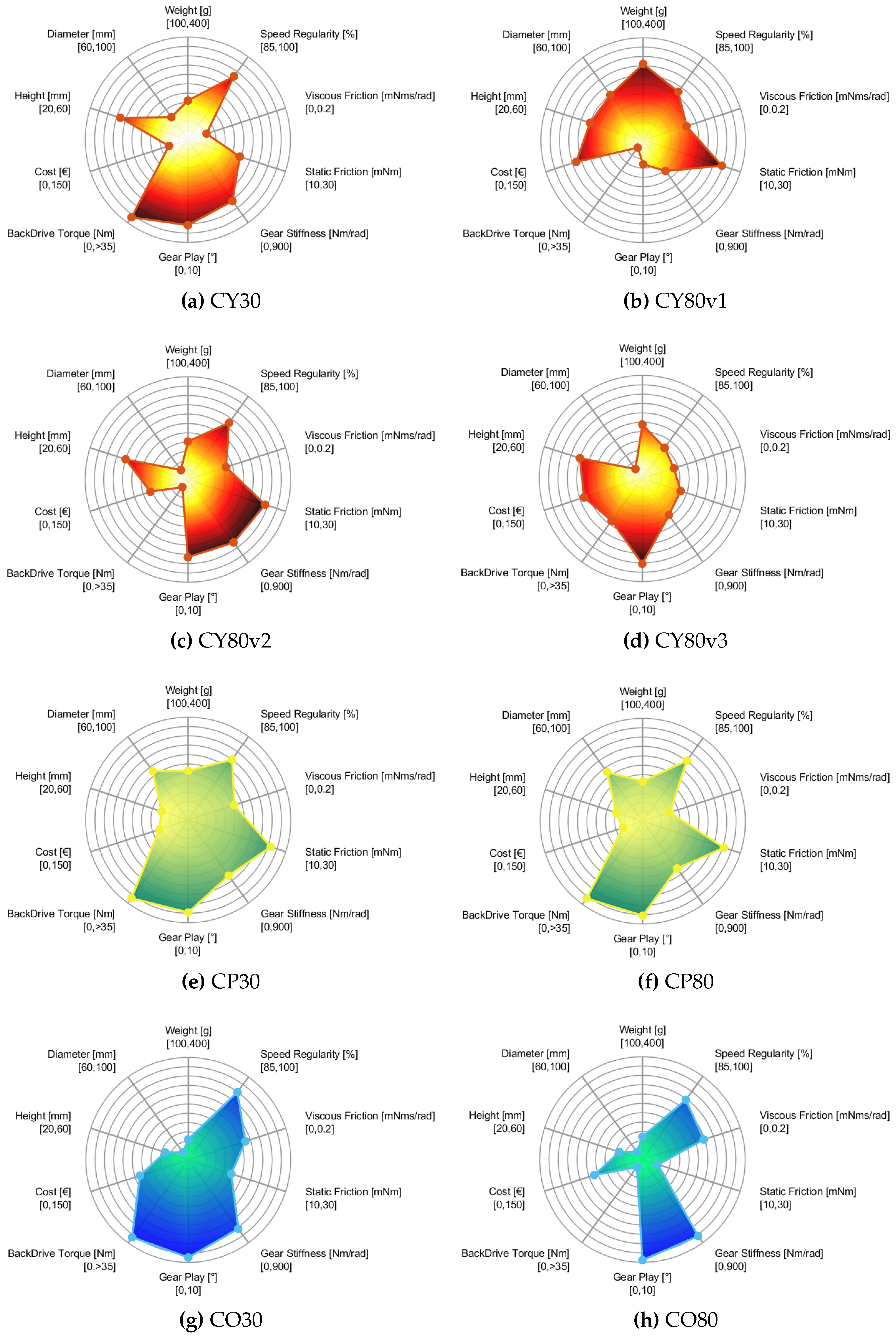
In
Figure 16 the spider plots of the examined features for each reducer are reported to allow a simple and comprehensive assessment of the examined mechanisms. We employed different colormaps for each of the three main architectures presented in this work (
CY,
CP,
CO). Each characteristic is presented on a scale whose maximum and minimum values are specified under the metrics’ names. These ranges of values were selected for an effective visual interpretation and comparison of the reducers. The best value in the considered range for each feature - i.e., small back drive torque, low cost, and low friction - is placed on the outer circumference. Thus, the bigger the area inside the spider plot, the better the related reducer.
Nonetheless, it should be noted that since the ranges were chosen appositely for comparison among these reducers, a minor area does not necessarily match a poor model, but a reducer with performances that result as inferior compared to the best one obtained in this work. Indeed, the experimental results showed that each designed reducer has some benefits and drawbacks. For example, concerning the cycloidal reducers, evident differences can be found both among the CY30 and the CY80 - due to the distinct architectures employed for the 1:30 and 1:80 gearboxes - and among the different implementations of the compact-double-disk design, that, as we expected, result strongly conditioned by features such as the number of rollers, the eccentricity, and the target dimensions.
From
Figure 16 it is clear that the
CP architecture maintains similar attributes despite the considerable difference between the transmission ratios. Indeed, the spider plots
Figure 16e,f show analogous shapes. The main differences regard the viscous friction and the cost as a consequence of the different number of rollers between the two reducers.
A similar consideration can be repeated for the compound reducers. In that case, however, a significant difference can be found in the back drive torque and static friction values (the CO80 reducer resulted non-backdriveable from our experiments).
Considering the implemented reduction ratios, the obtained weights, encumbrances, and prices turn out to be highly valuable for all the developed mechanisms. Even if some of the presented models have proven themselves not back-driveable, the other reducers showed significant performances regarding this feature. Concerning the identified friction components, it is clear that all proposed models exhibit considerable properties.
6. Conclusions and Future Works
In this study, we designed, developed, and compared multiple 3D-printed reducers conceived for wearable assistive devices.
To present a comprehensive evaluation of multiple features, we analyzed various transmission architectures providing light-weight and low-cost implementations of single and double-stage cycloidal reducers, planetary compound transmissions, and the series combination of cycloidal and planetary gearboxes in a double-stage reducer.
The general goal of our work was to investigate the prospect of using 3D-printed reducers in wearable exoskeletons, an approach that would lead to cost-effective and lightweight solutions. We examined different reducers’ properties (i.e., back drive torque, static and viscous friction, speed regularity, gear play, gear stiffness, encumbrance, weight, and cost) to inspect the different characteristics of each design and implementation and to inspect the relevance of the employment of these reducers for wearable devices. Indeed, the BOMs and the .stl files for reproducing the presented transmissions are available on request from the corresponding author.
The evaluation we carried out and the subsequent considerations are meant to clarify the strengths and limitations of each reducer’s 3D-printed implementation, to target the right architecture depending on the selected task requirements. To summarize, multiple reducers showed highly valuable performances across all the selected metrics, while others, notwithstanding their merits with respect to some of the analyzed features, require some improvements.
Comparing the numerical results, it is shown how the proposed series composition of cycloidal and planetary architectures proves to be valuable from multiple points of view. Thus, future works will aim to perfect this design, by improving its regularity and decreasing at the same time its cost and height. The planetary compound reducers need enhancements mainly regarding their encumbrance and weight. Concerning the 1:30 cycloidal reducer, a smaller diameter implementation could be tested (aiming to reduce also costs and viscous friction). Further exploration will be carried out for modeling a CY80 reducer that hopefully could combine the best features of the three implementations presented in this study.
A noteworthy limitation in our work is related to the use of the same material (PLA) for all the reducers’ printed components. Clearly, different designs (such as the teeth for gears or the lobes of the cycloidal disks) could benefit from the use of different materials available for FFF. Thus, future efforts will aim to investigate the influence of different materials on the metrics considered in this work, for enhancing the composition of each element in relation to its structural function. Once optimal materials are selected, we aim to optimize the design parameters to minimize encumbrance, weight, and cost of the presented reducers and improve their performances, to exploit them for a proper wearable exoskeleton.
Author Contributions
Conceptualization, R.B., A.F.; methodology, R.B., C.A.A., and A.F.; software, R.B., G.B., C.A.A., and A.F.; validation, R.B., G.B., and A.F.; formal analysis,R.B., A.F.; investigation,R.B.; resources, R.B., G.B., C.A.A., and A.F.; data curation, R.B.; writing—original draft preparation, R.B., G.B., and A.F.; writing—review and editing, R.B., G.B., C.A.A., and A.F.; visualization, R.B., A.F.; supervision, R.B., G.B.,and A.F.; project administration, A.F.; funding acquisition, R.B., C.A.A., and A.F.. All authors have read and agreed to the published version of the manuscript.
Funding
This research was funded by the Department of Excellence in Robotics and AI, Scuola Superiore Sant’Anna, 56127 Pisa, Italy.
Data Availability Statement
The data presented in this study (BOM and .stl files of the reducers’ components) are available on request from the corresponding author due to privacy.
Conflicts of Interest
The authors declare no conflicts of interest.
Appendix A. Non-Printed Components
In this appendix, the non-3D-printed components used for each of the developed reducers are reported in the following tables.
Table A1.
CY30 non-3D-printed components.
Table A1.
CY30 non-3D-printed components.
| Bearings |
Number of units |
Screws and nuts |
Number of units |
| 693 |
62 |
M3X30 |
2 |
| 61700 |
12 |
M3X25 |
31 |
| 6802 |
2 |
M3X16 |
6 |
| 6803 |
3 |
M3 nuts |
37 |
| 6808 |
1 |
|
|
Table A2.
CY80v1 non-3D-printed components.
Table A2.
CY80v1 non-3D-printed components.
| Bearings |
Number of units |
Screws and nuts |
Number of units |
| 693 |
19 |
M3X25 |
2 |
| 6802 |
3 |
M3X12 |
19 |
| 6803 |
1 |
M3X8 |
4 |
| 6808 |
1 |
M3 nuts |
23 |
Table A3.
CY80v2 non-3D-printed components.
Table A3.
CY80v2 non-3D-printed components.
| Bearings |
Number of units |
Screws and nuts |
Number of units |
| 693 |
49 |
M3X25 |
2 |
| 6803 |
4 |
M3X12 |
49 |
| 6808 |
1 |
M3X16 |
8 |
| |
|
M3 nuts |
57 |
Table A4.
CY80v3 non-3D-printed components.
Table A4.
CY80v3 non-3D-printed components.
| Bearings |
Number of units |
Screws and nuts |
Number of units |
| 693 |
19 |
M3X25 |
2 |
| 6803 |
4 |
M3X12 |
19 |
| 6808 |
1 |
M3X16 |
8 |
| |
|
M3 nuts |
27 |
Table A5.
CP30 non-3D-printed components.
Table A5.
CP30 non-3D-printed components.
| Bearings |
Number of units |
Screws and nuts |
Number of units |
| 693 |
22 |
M3X25 |
2 |
| MR95 |
12 |
M3X20 |
17 |
| 61700 |
13 |
M3X16 |
6 |
| 6802 |
3 |
M3 nuts |
23 |
| 6808 |
1 |
|
|
Table A6.
CP80 non-3D-printed components.
Table A6.
CP80 non-3D-printed components.
| Bearings |
Number of units |
Screws and nuts |
Number of units |
| 693 |
42 |
M3X25 |
2 |
| MR95 |
8 |
M3X20 |
27 |
| 61700 |
13 |
M3X16 |
4 |
| 6802 |
3 |
M3 nuts |
31 |
| 6808 |
1 |
|
|
Table A7.
CO30 non-3D-printed components.
Table A7.
CO30 non-3D-printed components.
| Bearings |
Number of units |
Screws and nuts |
Number of units |
| MR128 |
8 |
M3X30 |
1 |
| 61700 |
1 |
M4X40 |
4 |
| 6803 |
1 |
M4 nuts |
4 |
| 6810 |
2 |
|
|
| AX 75100 |
1 |
|
|
Table A8.
CO80 non-3D-printed components.
Table A8.
CO80 non-3D-printed components.
| Bearings |
Number of units |
Screws and nuts |
Number of units |
| MR128 |
8 |
M3X30 |
1 |
| 61700 |
1 |
M4X40 |
4 |
| 6803 |
1 |
M4 nuts |
4 |
| 6810 |
2 |
|
|
| AX 75100 |
1 |
|
|
References
- Shore, L.; Power, V.; De Eyto, A.; O’Sullivan, L. Technology acceptance and user-centred design of assistive exoskeletons for older adults: A commentary. Robotics 2018, 7, 3. [Google Scholar] [CrossRef]
- Zhao, C.; Liu, Z.; Zhu, L.; Wang, Y. Design and Research of Series Actuator Structure and Control System Based on Lower Limb Exoskeleton Rehabilitation Robot. Actuators 2024, 13, 20. [Google Scholar] [CrossRef]
- Mauri, A.; Lettori, J.; Fusi, G.; Fausti, D.; Mor, M.; Braghin, F.; Legnani, G.; Roveda, L. Mechanical and control design of an industrial exoskeleton for advanced human empowering in heavy parts manipulation tasks. Robotics 2019, 8, 65. [Google Scholar] [CrossRef]
- Stroppa, F.; Soylemez, A.; Yuksel, H.; Akbas, B.; Sarac, M. Optimizing Exoskeleton Design with Evolutionary Computation: An Intensive Survey. Robotics 2023, 12. [Google Scholar] [CrossRef]
- Baud, R.; Manzoori, A.; Ijspeert, A.; Bouri, M. Review of control strategies for lower-limb exoskeletons to assist gait. Journal Of NeuroEngineering And Rehabilitation 2021, 18, 1–34. [Google Scholar] [CrossRef] [PubMed]
- Calanca, A.; Toxiri, S.; Costanzi, D.; Sartori, E.; Vicario, R.; Poliero, T.; Di Natali, C.; Caldwell, D.; Fiorini, P.; Ortiz, J. Actuation selection for assistive exoskeletons: matching capabilities to task requirements. IEEE Transactions On Neural Systems And Rehabilitation Engineering 2020, 28, 2053–2062. [Google Scholar] [CrossRef] [PubMed]
- Barjuei, E.; Ardakani, M.; Caldwell, D.; Sanguineti, M.; Ortiz, J. Optimal selection of motors and transmissions in back-support exoskeleton applications. IEEE Transactions On Medical Robotics And Bionics 2020, 2, 320–330. [Google Scholar] [CrossRef]
- Yu, S.; Huang, T.; Yang, X.; Jiao, C.; Yang, J.; Chen, Y.; Yi, J.; Su, H. Quasi-direct drive actuation for a lightweight hip exoskeleton with high backdrivability and high bandwidth. IEEE/ASME Transactions On Mechatronics 2020, 25, 1794–1802. [Google Scholar] [CrossRef]
- Tiboni, M.; Borboni, A.; Vérité, F.; Bregoli, C.; Amici, C. Sensors and Actuation Technologies in Exoskeletons: A Review. Sensors 2022, 22. [Google Scholar] [CrossRef] [PubMed]
- Ko, H.; Lee, S.; Koo, D.; Lee, I.; Hyun, D. Waist-assistive exoskeleton powered by a singular actuation mechanism for prevention of back-injury. Robotics And Autonomous Systems 2018, 107, 1–9. [Google Scholar] [CrossRef]
- Li, Y.; Guan, X.; Han, X.; Tang, Z.; Meng, K.; Shi, Z.; Penzlin, B.; Yang, Y.; Ren, J.; Yang, Z. Others Design and preliminary validation of a lower limb exoskeleton with compact and modular actuation. IEEE Access 2020, 8, 66338–66352. [Google Scholar] [CrossRef]
- Mori, K.; Fujimoto, Y. Implementation of Motion Intention Prediction to Highly Back-Drivable Exoskeleton. IECON 2023-49th Annual Conference Of The IEEE Industrial Electronics Society 2023, 1–6. [Google Scholar]
- Zhu, H.; Nesler, C.; Divekar, N.; Peddinti, V.; Gregg, R. Design principles for compact, backdrivable actuation in partial-assist powered knee orthoses. IEEE/ASME Transactions On Mechatronics 2021, 26, 3104–3115. [Google Scholar] [CrossRef] [PubMed]
- Mian, S.; Abouel Nasr, E.; Moiduddin, K.; Saleh, M.; Alkhalefah, H. An Insight into the Characteristics of 3D Printed Polymer Materials for Orthoses Applications: Experimental Study. Polymers 2024, 16, 403. [Google Scholar] [CrossRef] [PubMed]
- Roveda, L.; Pesenti, M.; Rossi, M.; Rodriguez, M.; Pedrocchi, A.; Braghin, F.; Gandolla, M. User-centered back-support exoskeleton: design and prototyping. Procedia CIRP 2022, 107, 522–527. [Google Scholar] [CrossRef]
- Iizuka, K.; Takesue, N. Comparison of Characteristics of Internal Planetary Gear Reducer with Epitrochoid Curve using Metal and 3D Printed Parts. 2023 IEEE/SICE International Symposium On System Integration (SII) 2023, 1–6. [Google Scholar]
- Tunalioglu, M.; Agca, B. Wear and service life of 3-D printed polymeric gears. Polymers 2022, 14, 2064. [Google Scholar] [CrossRef] [PubMed]
- Zhang, Y.; Mao, K.; Leigh, S.; Shah, A.; Chao, Z.; Ma, G. A parametric study of 3D printed polymer gears. The International Journal Of Advanced Manufacturing Technology 2020, 107, 4481–4492. [Google Scholar] [CrossRef]
- Muminović, A.; Braut, S.; Božić, Ž.; Pervan, N.; Skoblar, A. Experimental failure analysis of polylactic acid gears made by additive manufacturing. Procedia Structural Integrity 2023, 46, 125–130. [Google Scholar] [CrossRef]
- Ciobanu, R.; Rizescu, C.; Rizescu, D.; Gramescu, B. Surface Durability of 3D-Printed Polymer Gears. Applied Sciences 2024, 14, 2531. [Google Scholar] [CrossRef]
- Buj-Corral, I.; Zayas-Figueras, E. Comparative study about dimensional accuracy and form errors of FFF printed spur gears using PLA and Nylon. Polymer Testing 2023, 117, 107862. [Google Scholar] [CrossRef]
- Jiang, S.; Hu, K.; Zhan, Y.; Zhao, C.; Li, X. Theoretical and experimental investigation on the 3D surface roughness of material extrusion additive manufacturing products. Polymers 2022, 14, 293. [Google Scholar] [CrossRef] [PubMed]
- Barsomian, C.; Eswaran, N.; Pesenti, M.; Gandolla, M.; Braghin, F.; Carpanzano, E.; Roveda, L. Dynamic characterization and control of a back-support exoskeleton 3D-printed cycloidal actuator. CIRP Annals, 2024. [Google Scholar]
- Sanchez, A.; Rossos, T.; Mihailidis, A.; Laschowski, B. Preliminary Development of a Robotic Hip-Knee Exoskeleton With 3D-Printed Backdrivable Actuators. International Design Engineering Technical Conferences And Computers And Information In Engineering Conference 2023, 87363, V008T08A072. [Google Scholar]
- Liu, Y.; Zhang, L.; Wang, R.; Smith, C.; Gutierrez-Farewik, E. Weight distribution of a knee exoskeleton influences muscle activities during movements. IEEE Access 2021, 9, 91614–91614. [Google Scholar] [CrossRef]
- Urs, K.; Adu, C.; Rouse, E.; Moore, T. Design and characterization of 3d printed, open-source actuators for legged locomotion. 2022 IEEE/RSJ International Conference On Intelligent Robots And Systems (IROS) 2022, 1957–1964. [Google Scholar]
- Yoshida, T.; Endo, G.; Okubo, A.; Nabae, H. Experimental Evaluation of a Quasi-direct-drive Actuator with a 3D-printed Planetary Gear Reducer. 2023 IEEE/SICE International Symposium On System Integration (SII) 2023, 1–6. [Google Scholar]
- Roozing, W.; Roozing, G. 3D-printable low-reduction cycloidal gearing for robotics. 2022 IEEE/RSJ International Conference On Intelligent Robots And Systems (IROS) 2022, 1929–1935. [Google Scholar]
- Roozing, W.; Roozing, G. Experimental comparison of pinwheel and non-pinwheel designs of 3D-printed cycloidal gearing for robotics. 2024 IEEE International Conference On Robotics And Automation (ICRA) 2024, 7091–7098. [Google Scholar]
- Chen, B.; Fang, T.; Li, C.; Wang, S. Gear geometry of cycloid drives. Science In China Series E: Technological Sciences 2008, 51, 598–610. [Google Scholar] [CrossRef]
- Blagojevic, M.; Marjanovic, N.; Djordjevic, Z.; Stojanovic, B.; Disic, A. A new design of a two-stage cycloidal speed reducer. 2011. [Google Scholar]
- Lin, T.; Schabacker, M.; Ho, Y.; Kuo, T.; Tsay, D. Geometric Design and Dynamic Analysis of a Compact Cam Reducer. Machines 2022, 10, 955. [Google Scholar] [CrossRef]
- Lin, W.; Shih, Y.; Lee, J. Design of a two-stage cycloidal gear reducer with tooth modifications. Mechanism And Machine Theory 2014, 79, 184–197. [Google Scholar] [CrossRef]
- Kapelevich, A.; AKGears, L. High gear ratio epicyclic drives analysis. Ratio 2013, 3. [Google Scholar]
- Matsuki, H.; Nagano, K.; Fujimoto, Y. Bilateral drive gear—a highly backdrivable reduction gearbox for robotic actuators. IEEE/ASME Transactions On Mechatronics 2019, 24, 2661–2673. [Google Scholar] [CrossRef]
- Huang, X.; Rui, Y.; Wang, C.; Huang, H.; Zhang, Z.; Fan, C.; Yang, Y. Gravity Compensation Based Control for Lower-Limb Load-Bearing Exoskeleton. 2021 6th International Conference On Control, Robotics And Cybernetics (CRC) 2021, 230–234. [Google Scholar]
- Satake, H.; Takesue, N. Comparison of Characteristics of Cycloidal Gear Reducer Using Metal, Plastic and 3D Printed Parts. 2024 IEEE/SICE International Symposium On System Integration (SII) 2024, 1531–1536. [Google Scholar]
Figure 1.
Schematic illustrations of the structure of the single-stage cycloidal reducer. Both the lateral (a) and frontal (b) view are reported for clarity. The acronyms are abbreviations for the part of the same color. IN is the input shaft (in black) with eccentric sections. FCB is the Fixed Cycloidal Base (in yellow), which the rollers (R, still in yellow) are connected to. D1 and D2 are the two cycloidal Disks, in green. CC is the Cycloidal Carrier (in blue), which is composed of a certain number of pins (P) that takes motion from the interaction with the cycloidal disk holes (H). The carrier represents the output of this reducer.
Figure 2.
Schematic illustrations of the structure of the double-stage cycloidal reducer. On the left the dual-stage double-disk architecture is represented (a), while on the right side, a scheme of the compact-disk double-stage cycloidal reducer (b) is reported. The acronyms are abbreviations for the part of the same color. IN is the input shaft (in black) with eccentric sections. FCB is the Fixed Cycloidal Base (in yellow), to which the rollers (R, still in yellow) are connected. D1 and D2 are the two different cycloidal Disks, that are connected to the same shaft and carrier but are in contact with two different groups of rollers. CC is the Cycloidal Carrier (in blue). CD is the Compact Disk, a part that includes two joint cycloidal disks moved by the same shaft but engaged with different sets of rollers. MCB is the Moving Cycloidal Base, another part connected to a set of rollers (in purple), that gets its motion from the interaction with the second disk D2 and corresponds to the output of this reducer.

Figure 3.
Schematic illustration of the structure of the cycloidal-planetary series (CP) reducer. The acronyms reported are abbreviations for the part of the same color. IN is the input shaft (in black) with a single eccentric section. FCB is the Fixed Cycloidal Base (in yellow), to which the rollers (R, still in yellow) are connected. CD is the Cycloidal Disk. CC is the Cycloidal Carrier (in light blue), which is composed of another consequent section (that is to say the Planetary Sun S joined to the first one. P stands for Planet (in red), while FPR is the Fixed Planetary Ring, that is rigidly connected to the cycloidal base. PC is the Planetary Carrier that corresponds to the output of this reducer.
Figure 4.
Schematic illustration of the structure of the planetary compound (CO) reducer. The acronyms reported are abbreviations for the part of the same color. IN is the input shaft (in black), that corresponds to the planetary Sun SA of the Stage A of the compound reducer. FRA is the planetary Fixed Ring of the Stage A (in yellow). CP is the compound Planet (in red), composed of two joint planets (PA and PB, respectively Planet of Stage A and Planet of Stage B). CC is the Compound Carrier (in blue) to which the compound planets are connected. MRB is the planetary Moving Ring of Stage B, that corresponds to the output of this reducer.
Figure 5.
Exploded view of the cad model of the cycloidal (CY30) reducer. Bearings, nuts, and screws have been hidden for a better comprehensibility of the Figure. The distinct elements illustrated with the same color (the upper and lower part of the Fixed Cycloidal Base, as well as the two parts of the Cycloidal Carrier) are rigidly connected through screws in the final assembly.
Figure 6.
Exploded views of the cad models of the three cycloidal double-stage compact-disk reducers (CY80v1, CY80v2, and CY80v3). Bearings, nuts, and screws are not shown for a better comprehensibility of Figure. The distinct elements illustrated with the same color (the upper and lower part of the Fixed Cycloidal Base) are rigidly connected through screws in the final assembly.
Figure 7.
Exploded views of the cad models of both the cycloidal-planetary reducers (CP30 and CP80). Bearings, nuts, and screws are not shown for a better comprehensibility of Figure. For the same reason, not all the planets are represented. The distinct elements illustrated with the same color (the Fixed Cycloidal Base with the Fixed Planetary Ring, the two parts of the Cycloidal Carrier, and the two parts of the Planetary Carrier) are rigidly connected through screws in the final assembly.
Figure 8.
Exploded view of the cad model of both the planetary compound reducers (CO30 and CO80). Bearings, nuts, and screws have been hidden for better comprehensibility of the figure. For the same reason, not all four planets are represented. The distinct elements illustrated with the same color (the three parts of the Compound Carrier) are rigidly connected through screws in the final assembly.
Figure 9.
Experimental apparatus for testing the reducers. In Figures (a) and (b) the cad models of the C1 and C2 arrangements of the experimental setup are reported for a clearer view. (c) Photos and notes to clarify the composition of the experimental setup (the reducer is the CO80) both in the configuration with and without the output arm and the loadcells.
Figure 10.
Representation of the data from one of the performed speed regularity tests. The reference signal (in blue) consists of a series of speed steps (from 0 rad/s to 120 rad/s, with steps of 20 rad/s). The other signals represent the motor and the reducer’s output velocities (the latter has been corrected through the reduction ratio, i.e., i, to plot it together with the motor’s speed).
Figure 11.
Example of the friction model identification of a reducer. The motor torque signal (in blue) was derived by multiplying the registered motor current by the motor’s torque constant. Then, the resulting torque values were employed to find the friction model’s parameters and plot the fitting function (in red).
Figure 12.
The identified friction torques for the presented reducers. (a) present the results regarding the 1:30 reducers and (b) reports the models regarding the 1:80 reducers.
Figure 12.
The identified friction torques for the presented reducers. (a) present the results regarding the 1:30 reducers and (b) reports the models regarding the 1:80 reducers.
Figure 13.
Instance from an experimental stiffness identification procedure. The reducer’s output angular displacements are reported based on the respective torque value. Each box plot represents the distribution of the displacement data for each of the torque samples. The linear function describes the stiffness approximation for the CO30 reducer.
Figure 14.
Comprehensive illustration of the linear fitted functions that approximate the reducers’ stiffness based on the experimental displacement-torque data. The two reported plots present the torque-displacement mean values for each of the examined torques (displayed through different shapes based on the reducers’ architecture) and the linear fit functions. Figure (a) presents the results regarding the 1:30 reducers and figure (b) reports the plot concerning the 1:80 reducers.
Figure 15.
Photos of the designed reducers on the balance employed for verifying their weights.
Figure 15.
Photos of the designed reducers on the balance employed for verifying their weights.
Figure 16.
Spider-plots that summarize the reducers’ performances regarding the considered metrics. For each feature, the unit of measurement is specified together with the minimum and maximum values that can be reached in the plot. The best value for each metric is set on the outer circumference, which means that the larger the area inside the plot, the better the reducer.
Table 1.
CY30 reducer design parameters.
Table 1.
CY30 reducer design parameters.
| Parameter |
Value |
| Fixed cycloidal base radius (rollers location) |
41 mm |
| Number of rollers |
31 |
| Rollers radius |
4 mm |
| Eccentricity |
1 mm |
| Number of the carrier output pins |
6 |
| Output pin radius |
4 mm |
| Carrier radius |
24 mm |
Table 2.
Design parameters of the three versions of the CY80 reducer.
Table 2.
Design parameters of the three versions of the CY80 reducer.
| Parameter |
CY80v1 |
Cy80v2 |
CY80v3 |
| Fixed cycloidal base radius A (rollers location) |
18.1 mm |
28.5mm |
28.5mm |
| Number of rollers A |
9 |
21 |
9 |
| Moving cycloidal base radius B (rollers location) |
18.1 mm |
37 mm |
37mm |
| Number of rollers B |
10 |
28 |
10 |
| Rollers radius |
4 mm |
4mm |
4mm |
| Eccentricity |
1 mm |
0.8 mm |
2.5 mm |
Table 3.
Design parameters of the CP30 and CP80 reducers.
Table 3.
Design parameters of the CP30 and CP80 reducers.
| Parameter |
CP30 |
CP80 |
| Fixed Cycloidal base radius (rollers location) |
35 mm |
35 mm |
| Number of rollers |
11 |
21 |
| Rollers radius |
4 mm |
4 mm |
| Eccentricity |
1.2 mm |
1.2 mm |
| Number of cycloidal carrier output pins |
6 |
6 |
| Output pin radius |
3.8 mm |
3.8 mm |
| Cycloidal Carrier radius |
21 mm |
21 mm |
| Number of teeth Ring |
52 |
51 |
| Number of teeth Planets |
13 |
17 |
| Number of teeth Sun |
26 |
17 |
| Number of planets |
6 |
4 |
| Teeth Module |
1 mm |
1mm |
| Teeth Pressure angle |
25° |
25° |
| Planetary Carrier Radius |
19.5 mm |
17 mm |
Table 4.
Design parameters of the CO30 and CO80 reducers.
Table 4.
Design parameters of the CO30 and CO80 reducers.
| Parameter |
CO30 |
CO80 |
| Number of teeth Ring A |
58 |
54 |
| Number of teeth Planets A |
20 |
16 |
| Rotation angle Planets A |
81° |
123.75° |
| Number of teeth Sun A |
18 |
22 |
| Number of teeth Ring B |
54 |
55 |
| Number of teeth Planets B |
16 |
17 |
| Rotation angle Planets B |
123.75° |
111.176° |
| Number of planets |
4 |
4 |
| Teeth Module |
1.2 mm |
1.2 mm |
| Teeth Pressure angle |
25° |
25° |
| Carrier Radius |
22.8 mm |
22.8 mm |
Table 5.
Regularity of the reducers at the investigated motor velocities.
Table 5.
Regularity of the reducers at the investigated motor velocities.
| Motor Speed [rad/s] |
20 |
40 |
60 |
80 |
100 |
120 |
| CY30 Regularity [%] |
96.05 |
95.29 |
95.65 |
97.37 |
96.4 |
95.9 |
| CO30 Regularity [%] |
97.86 |
96.55 |
95.88 |
96.75 |
97.09 |
96.41 |
| CP30 Regularity [%] |
95.5 |
94.8 |
95.77 |
95.85 |
94.87 |
96.25 |
| CP80 Regularity [%] |
95.9 |
96.88 |
94.9 |
94.35 |
95.51 |
95.68 |
| CO80 Regularity [%] |
94.4 |
94.89 |
95.33 |
96.51 |
95.07 |
95.84 |
| CY80v1 Regularity [%] |
91.29 |
92.3 |
92.73 |
92.12 |
93.87 |
93.43 |
| CY80v2 Regularity [%] |
93.85 |
93.1 |
95.69 |
95.97 |
94.55 |
95.28 |
| CY80v3 Regularity [%] |
88.58 |
89.41 |
90.82 |
89.32 |
88.87 |
90.36 |
Table 6.
Table of the results from the tests carried out with the C1 experimental setup.
Table 6.
Table of the results from the tests carried out with the C1 experimental setup.
| ID |
Regularity [%] |
Static Friction [mNm] |
Viscous Friction [mNms/rad] |
| CY30 |
96.11 ± 0.72 |
|
|
| CY80v1 |
93.12 ± 1.70 |
|
|
| CY80v2 |
94.76 ± 1.1 |
|
|
| CY80v3 |
89.56 ± 0.86 |
|
|
| CO30 |
96.96 ± 0.59 |
|
|
| CO80 |
95.34 ± 0.75 |
|
0.82
|
| CP30 |
95.51 ± 0.57 |
13.4
|
|
| CP80 |
95.54 ± 0.87 |
|
|
Table 7.
Table of the results from the tests carried out with the C2 experimental setup.
Table 7.
Table of the results from the tests carried out with the C2 experimental setup.
| ID |
Backdrive Torque [Nm] |
Gear Play [°] |
Gear Stiffness [Nm/rad] |
| CY30 |
0.66 ± 0.032 |
1.85 ± 0.39 |
641.4 ± 72.73 |
| CY80v1 |
> 35 |
8.41 ± 0.58 |
278.1 ± 33.62 |
| CY80v2 |
> 35 |
2.69 ± 0.34 |
659.5 ± 52.54 |
| CY80v3 |
4.89 ± 0.385 |
1.89 ± 0.41 |
344.7 ± 36.54 |
| CO30 |
0.67 ± 0.040 |
0.53 ± 0.21 |
723.2 ± 71.05 |
| CO80 |
> 35 |
0.23 ± 0.11 |
821.7 ± 57.72 |
| CP30 |
0.59 ± 0.030 |
1.1 ± 0.14 |
573.6 ± 59.52 |
| CP80 |
0.70 ± 0.044 |
0.89 ± 0.23 |
472.5 ± 43.15 |
Table 8.
Table of the encumbrance, weight and cost of the presented reducers.
Table 8.
Table of the encumbrance, weight and cost of the presented reducers.
| ID |
Diameter [mm] |
Height [mm] |
Weight [g] |
Cost ] |
| CY30 |
92 |
33.5 |
304 |
133.05 |
| CY80v1 |
80 |
40 |
184 |
51.34 |
| CY80v2 |
99 |
36.5 |
308 |
101.71 |
| CY80v3 |
99 |
36.5 |
257 |
66.95 |
| CO30 |
100 |
53.6 |
364 |
83.17 |
| CO80 |
100 |
53.6 |
358 |
83.71 |
| CP30 |
78 |
52 |
272 |
116.26 |
| CP80 |
78 |
52 |
302 |
131.42 |
|
Disclaimer/Publisher’s Note: The statements, opinions and data contained in all publications are solely those of the individual author(s) and contributor(s) and not of MDPI and/or the editor(s). MDPI and/or the editor(s) disclaim responsibility for any injury to people or property resulting from any ideas, methods, instructions or products referred to in the content. |
© 2024 by the authors. Licensee MDPI, Basel, Switzerland. This article is an open access article distributed under the terms and conditions of the Creative Commons Attribution (CC BY) license (http://creativecommons.org/licenses/by/4.0/).
