Preprint
Article

Joint Design of Altitude and Channel Statistics Based Energy Beamforming for UAV-Enabled Wireless Energy Transfer

Altmetrics

Downloads

58

Views

66

Comments

0

A peer-reviewed article of this preprint also exists.

This version is not peer-reviewed

Submitted:

26 October 2024

Posted:

28 October 2024

You are already at the latest version

Alerts
Abstract
In recent years, UAV-enabled wireless energy transfer (WET) has attracted significant attention for its ability to provide efficient and stable power for ground devices by flexibly navigating 3-dimensional (3-D) space and utilizing the favorable line-of-sight (LoS) channels. Meanwhile, energy beamforming utilizing multiple antennas has been touted as a key technology to substantially enhance the radio frequency (RF)-based WET efficiency by focusing energy beams towards devices in desirable directions. However, energy beamforming design for UAV-enabled WET systems has not been studied, despite its tremendous utility. In this paper, we propose a joint design of the UAV’s altitude and channel statistics based energy beamforming to minimize the overall charging time required for all energy havesting devices (EHDs) to meet their energy demands, while alleviating the additional resources and cost for channel estimation. Unlike previous works that considered only the LoS dominant channel without small-scale fading, we adopt a more general air-to-ground (A2G) Rician fading channel, where the LoS probability as well as the Rician factor depends on the UAV’s altitude. To tackle the highly non-convex and non-linear problem, we first examine a single EHD scenario in order to draw insights by deriving an optimal energy beamformihng in a closed-form, and then devise the efficient methods to jointly design the altitude and energy beamforming for a multiple EHDs scenario. Our numerical results exhibit that the proposed joint design considerably reduce the overall charging time, while benefiting from significantly lowering the computational complexity compared the conventional methods.
Keywords: 
Subject: Engineering  -   Electrical and Electronic Engineering

1. Introduction

Radio frequency (RF)-based wireless energy transfer (WET) is a key enabling technology for developing intelligent and self-sustaining Internet of Everything (IoE) networks in the 6G era [1,2,3,4,5,6,7]. It enables the continuous supply of power to wireless devices over the air, such as wearable electronic devices, extended reality devices, and robotics, without the need for frequent battery replacements or wired power lines. Moreover, compared to traditional power systems, RF-based WET can significantly enhance the quality of service for powering devices by adapting to different physical conditions and service requirements while also improving throughput and robustness [1,2,3].
In recent years, unmanned aerial vehicles (UAVs) have gained significant attention in various scenarios due to their deployment flexibility, mobility, and cost-effectiveness, leading to widespread adoption across various applications, including military operations, cargo delivery, disaster management, and communication platforms [8,9,10,11,12,13,14,15]. They provide greater flexibility in system design and operation within wireless networks by allowing adjustments to the deployment position and path of UAVs, yielding significant advantages such as coverage enhancements [8,9,10,11,12,13,14,15].
Thanks to its potential advantages, UAV-enabled wireless energy transfer (WET) has received great attention for providing ground devices with more efficient and stable power compared to conventional WET systems, which use fixed-location energy transmitters [15,16,17,18,19,20,21,22,23,24]. In particular, UAVs are able to move flexibly in three-dimensional (3D) space, utilizing favorable line-of-sight (LoS) channels with ground devices. As such, UAVs can serve as a new type of aerial energy transmitter, reducing the transmission distances for powering devices while avoiding obstacles and shadow fading, even in remote areas where conventional fixed-location energy transmitters are not available. Accordingly, UAV-enabled WET is able to overcome energy bottlenecks as well as meet urgent energy demands, thereby extending the operational lifespan of energy-constrained devices, especially in dynamic or hard-to-reach environments such as smart cities, wireless sensor networks, and maritime networks, among others [15,16,17,18]. However, effective UAV trajectory design is required to reap potential gains from UAV-enabled WET.
In practical UAV-enabled WET scenarios, a UAV may move closer to a device in order to reduce the transmission distance for improved power efficiency. This may result in the UAV moving farther away from another device, thereby decreasing the overall energy transfer efficiency. To address this challenge, UAV trajectory design has been extensively studied to improve the energy transfer performance for multiple devices [15,16,17,18,19,20,21]. Specifically, in a single UAV-enabled WET system, an optimal one-dimensional (1D) trajectory design at a fixed altitude was proposed to maximize the minimum received energy among all devices during a given charging period [16]. For a more general context, the design of a two-dimensional (2D) UAV trajectory at a fixed altitude was studied to optimize the energy transferred to all devices during a given charging period [17], with further investigations in a more practical scenario [18]. Moreover, the design of a 3D UAV trajectory within a specified altitude range was explored to maximize the total received energy across all devices for a given charging period [19]. The joint design of 2D UAV trajectory and orientation of 1D directional antenna array at the UAV with a fixed altitude was also studied [20] and further extended to a structure that includes a 3D directional antenna array at the UAV [21]. Moreover, a multi-UAV-enabled WET system capable of covering a large area was proposed, and effective trajectory designs for multiple UAVs were studied to enhance energy transfer performance across various scenarios [15,22,23,24].
Meanwhile, energy beamforming has been recognized as a promising technology for significantly increasing the energy transfer efficiency of RF-based WET systems, particularly compared to single-antenna omni-directional transmission [2,3,4]. An energy transmitter with multiple antennas can simultaneously focus energy beams toward devices in the desired directions, thereby overcoming high propagation path loss without increasing transmit power or bandwidth. In this regard, various energy beamforming techniques have been proposed for use in terrestrial wireless networks with perfect channel state information (CSI) as well as with imperfect CSI [3,4,5,6,7]. Moreover, due to the advantage of having LoS channels, beamforming techniques combined with resource allocation and optimization have been widely considered to enhance power transfer performance in various UAV-enabled systems [25]. Beamforming combined with optimization of placement and resource allocation has been studied to maximize energy efficiency in wireless-powered UAV communication systems with non-orthogonal multiple access (NOMA) [26]. Additionally, hybrid beamforming with resource allocation has been explored in UAV-enabled wireless-powered mobile edge computing networks [27]. Furthermore, the joint optimization of beamforming, transmit power, power-splitting ratio, and UAV trajectory was proposed to enhance communication performance in UAV-enabled relay networks with wireless power transfer [28]. For UAV-enabled wireless-powered communication networks (WPCNs), beamforming techniques have also been explored using a backscattering scheme [29] and reconfigurable intelligent surfaces (RIS) [30], by jointly optimizing time allocation. Various beamforming techniques for UAV-enabled systems have been proposed in conjunction with resource allocation and optimization. However, existing studies have primarily focused on wireless-powered communication systems (WPCNs) or simultaneous wireless information and power transfer (SWIPT) systems, with an emphasis on optimizing communication performance. To the best of our knowledge, despite its significant utility, an energy beamforming technique that focuses solely on increasing energy transfer efficiency to simultaneously charge multiple devices, rather than on communication performance, has not been fully studied to realize its potential gains in UAV-enabled WET systems.
Motivated by the aforementioned observations, we focus on energy beamforming design to optimize energy transfer efficiency for UAV-enabled WET systems. In practical WET networks, multiple devices have different energy requirements, and their charging times vary based on the amount of energy needed. Therefore, UAV altitude and energy beamforming must be optimized accordingly. To this end, this paper investigates a joint design of UAV altitude and energy beamforming to minimize the overall charging time required for all energy-harvesting devices (EHDs) to meet their energy requirements. Thus, a large number of EHDs are efficiently served simultaneously while avoiding unnecessary energy transfer from the UAV. Our main contributions are summarized as follows:
  • We propose the joint design of UAV altitude- and channel statistics-based energy beamforming, where the EHDs’ energy demands are considered in efficiently and simultaneously serving the EHDs while reducing the additional resources and costs associated with obtaining perfect channel state information. In contrast to existing works on UAV-enabled WET, which consider only the LoS dominant channel without small-scale fading, we adopt the more general air-to-ground (A2G) Rician fading channel while also taking into account the characteristic nature of the aerial channel in practical UAV scenarios, where the channel statistics depend on the altitude of the UAV.
  • Due to the highly non-convex and non-linear nature of our design problem, we first jointly optimize UAV altitude and energy beamforming in a single-EHD scenario to draw insights. We derive a solution for optimal energy beamforming in closed form, thereby developing an efficient algorithm with low complexity in obtaining the optimal solution.
  • We devise an efficient algorithm to jointly optimize the UAV altitude and energy beamforming in a scenario with multiple EHDs by investigating the optimal conditions as well as the dual problem. Motivated by insights from the design for a single-EHD scenario, we also develop an efficient low-complexity method for determining near-optimal altitude and energy beamforming. Moreover, we explore a sub-optimal design by leveraging weighted-sum energy beamforming in closed form with considerably reduced computational complexity.
  • The numerical results demonstrate that compared to conventional methods, the proposed methods can significantly reduce the overall charging time while also decreasing the computational complexity.
The rest of this paper is organized as follows. In Section 2, we introduce the system model and formulate our design problem. In Section 3, we jointly optimize UAV altitude and energy beamforming for a single-EHD scenario. In Section 4, we propose the methods for jointly optimizing UAV altitude and energy beamforming in a multiple-EHD scenario. We evaluate our proposed methods in Section 5 and conclude our paper in Section 6.

2. System Model and Problem Formulation

2.1. System Model

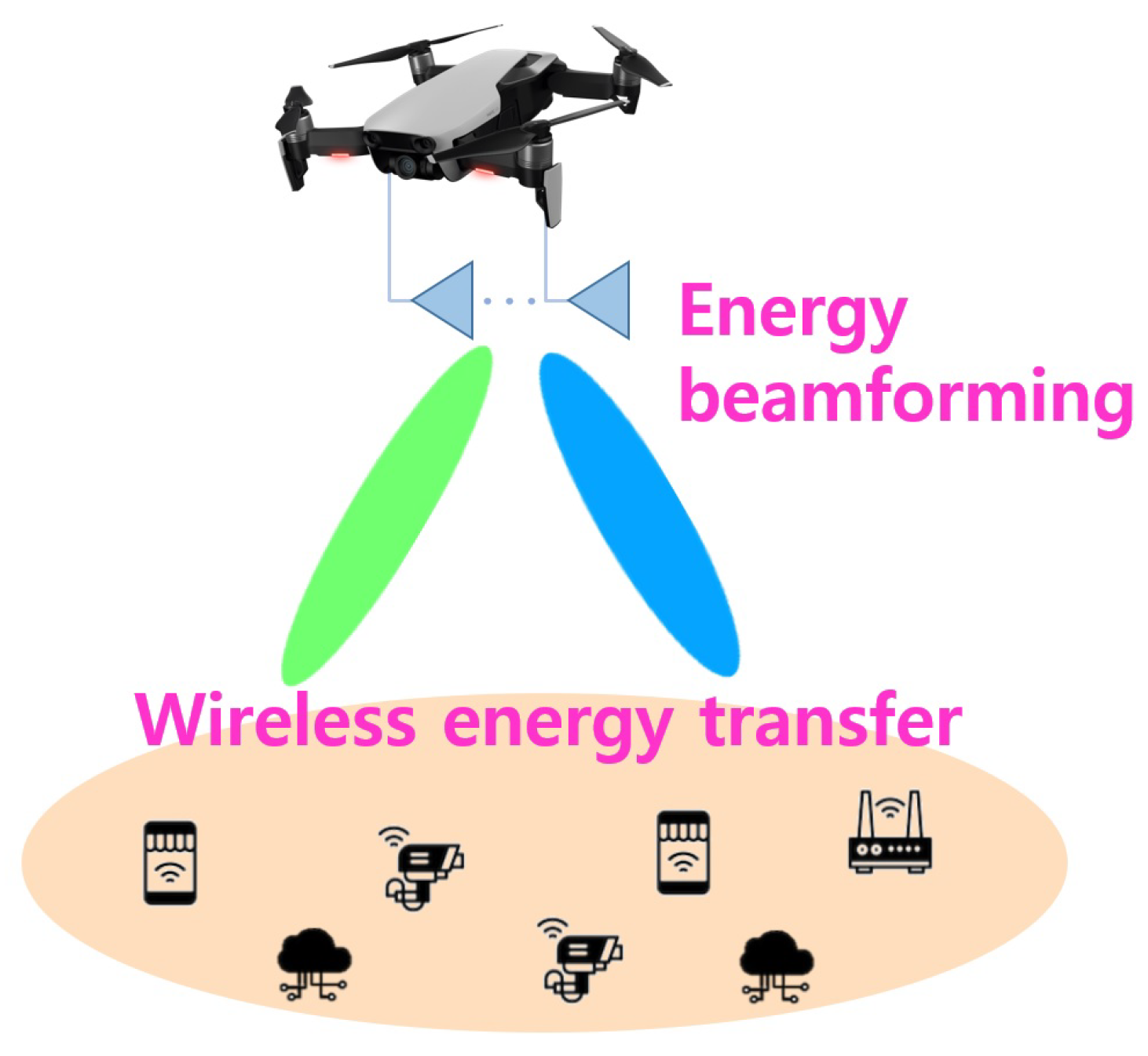
As depicted in Figure 1, we consider a UAV-enabled RF-based wireless energy transfer (WET) system where one UAV simultaneously transfers power to U energy-harvesting devices (EHDs) on the ground, such as IoT devices and sensors. The UAV is equipped with N transmitting antennas, and the EHDs are equipped with a single antenna. The UAV hovers over the central EHDs with an altitude h [ H min , H max ] in order to conserve power for flight, where H min and H max denote the minimum and maximum altitude of the UAV, respectively. In addition, the maximum WPT coverage of the UAV on the ground is denoted as r max . The horizontal distance between the UAV and u-th EHD, where u U { 1 , . . . , U } , is denoted by r u r max .
Let w b C N be the b-th energy beamforming vector transmitted from the UAV to the EHDs where b B { 1 , . . . , B } and B ( N ) is the number of energy beams to be determined. Then, the transmitted signal vector at the UAV for the power transfer, denoted by x C N , is given as
x = b = 1 B w b s b
where s b is the energy-bearing signal with zero mean and unit variance, i.e., E [ | s b | 2 ] = 1 , which can have an arbitrary distribution, since s b does not carry any information [1,2,3]. In this case, the transmit covariance matrix at the UAV, denoted by X H N , becomes
X = b = 1 B w b w b H 0
where H N represents the set of N-by-N Hermitian matrices. It is assumed that the UAV has a transmit sum power constraint of P; then, the transmit covariance matrix of (2) must satisfy Tr ( X ) P .

2.2. Aerial Channel Model

In this paper, we adopt an air-to-ground (A2G) Rician fading channel by considering the characteristic nature of the aerial channel in practical scenarios, where the channel statistics depend on the UAV altitude [11,12,13,14,31]. A Rician fading channel consists of a deterministic line-of-sight (LoS) component as well as a random multipath component, i.e., Rayleigh-distributed non-LoS (NLoS). Thus, the A2G Rician fading channel model characterizes the aerial channel by taking into account the dominant LoS channel and the multiplicative effect of both large- and small-scale fading. The channel vector between the UAV and u-th EHD, denoted by u C N × 1 , is modeled by [14,31].
u = β 0 d u α u K u K u + 1 a u + 1 K u + 1 h u NLoS
where β 0 is the path loss at the reference distance; d u and α u denote the distance and path loss exponent between the UAV and u-th EHD, respectively. a u C N × 1 is the deterministic LoS component; h u NLoS C N × 1 is the NLoS component distributed with h u NLoS C N ( 0 , I N ) ; K u denotes the Rician factor which reflects the power ratio of the LoS component and NLoS component. Assuming there is a uniform linear array (ULA) at the UAV, the LoS component is represented by
a u = 1 , e j 2 π d a λ c sin ( ϕ u ) , , e j 2 π ( N 1 ) d a λ c sin ( ϕ u ) T
where λ c is the carrier wavelength, d a is the space between adjacent antennas, and ϕ u is the angle of departure (AoD) [14,31].
Since the propagation characteristics of the A2G channel, such as obstacle density and link quality, are affected by the altitude of the UAV [8,9,10,11,12,13,14], we model not only the probability of a link having a LoS component but also the values of the path loss exponent and Rician factor as a function of UAV altitude, as follows. First, the distance and elevation angle (in radians) between the UAV and u-th EHD are respectively given by
d u = r u 2 + h 2 ,
θ u = arctan h r u .
Then, the LoS probability can be modeled as a function of the elevation angle: [11,12,13,14]
P LoS ( θ u ) = 1 1 + a 1 exp b 1 180 π θ u a 1
where a 1 and b 1 are positive parameters that are determined by environmental characteristics, i.e., Suburban, Urban, Dense Urban, and Highrise Urban [8,9,10]. The value of the path loss exponent is typically proportional to the LoS probability, so α u can be modeled as [11,12,13,14]
α u = a 2 P LoS ( θ u ) + b 2 .
In (8), the coefficients of a 2 and b 2 are given by
a 2 = α π 2 α 0 1 + a 1 exp ( a 1 b 1 ) a 1 exp ( a 1 b 1 )
b 2 = α 0 a 2 1 + a 1 exp ( a 1 b 1 )
where α 0 and α π 2 are the path loss exponents of ground and aerial links, which are determined through measurement [10,11,12]. Here, a 2 < 0 and b 2 > 0 , and a 2 α π 2 α 0 and b 2 α 0 , where the approximations come from P LoS ( 0 ) 0 and P LoS π 2 1 . In addition, with respect to θ u , α u is a monotonic function decreasing from α 0 to α π 2 .
In addition, the Rician factor depends on the LoS probability and is thus characterized by the elevation angle of the UAV. In this regard, K u can be modeled in dB units using an exponential function of θ u [11,13,32], as follows:
K u dB = a 3 exp b 3 θ u
where a 3 and b 3 are environment- and frequency-dependent constant parameters that are given by [11,13,32]
a 3 = K 0 dB , b 3 = 2 π ln K π 2 dB K 0 dB .
In (12), K 0 dB and K π 2 dB are the Rician factors in dB units when the elevation angles are 0 rad and π 2 rad, respectively, which are obtained from measurements [32]. In addition, with respect to θ u , K u dB is monotonic function increasing from K 0 dB to K π 2 dB .

2.3. Formulation of the Energy Harvesting Optimization Problem

By denoting τ u as the charging time of the u-th EHD, the energy harvested at the u-th EHD is given by [1,2,3,4,5]
Q u = ζ u τ u Tr h u h u H X , u U
where ζ k ( ( 0 , 1 ] ) is the energy-harvesting efficiency, which is determined by the circuit. Without loss of generality, we set ζ 1 = = ζ U = 1 for simplicity. However, any constant efficiency values can be integrated into our energy-harvesting optimization problem.
When the energy requirement from the u-th EHD is represented by Q u Req > 0 , the required charging time at the u-th EHD to meet the energy requirements is given by τ u = Q u Req Tr ( h u h u H X ) . On the other hand, obtaining perfect channel state information (CSI) at the UAV for energy beamforming design requires additional resources and cost for channel estimation, which is not expected to be feasible in practice due to the high energy consumption and computational complexity [2,4,5,15]. Therefore, we explore only channel statistics in the joint design of UAV altitude and energy beamforming. In the context of optimization for energy harvesting, we focus on the long-term channel statistics, i.e., E h u h u H , rather than the perfect CSI of h u h u H [4,5,7]. To this end, we consider the expected required charging time at the u-th EHD, which is represented as
τ u = Q u Req Tr ( E [ h u h u H ] X ) , u U .
In consideration of the different energy requirements across all EHDs, i.e., [ Q u Req ] u = 1 U , the overall charging time required for all EHDs to meet their energy demands becomes max ( τ 1 , . . . , τ U ) [3,6,7]. Our design objective is to jointly optimize UAV altitude and energy beamforming to minimize the overall charging time required to meet the energy demands of all EHDs by leveraging only on channel statistics. Consequently, our design problem is formulated as
P 1 : min h , X max ( τ 1 , . . . , τ U )
s . t . τ u = Q u Req Tr E [ h u h u H ] X , u U ,
Tr ( X ) P ,
X 0 ,
H min h H max .
In the problem P 1 , the constraints (16) and (17) follow from the transmit sum power constraint and (2), respectively, and the constraint (18) indicates the UAV altitude range with h [ H min , H max ] . In practical UAV operations, altitude adjustments should consider regulatory constraints such as maximum allowable altitude, no-fly zones, and airspace restrictions, as well as practical factors like energy consumption and safety management [33,34,35].
Additionally, from (3), E [ h u h u H ] in (15) is expressed as
E [ h u h u H ] = β 0 d u α u K u K u + 1 a u a u H LoS + 1 K u + 1 I N NLoS G u ( h ) ,
where d u , α u , and K u are optimization functions for the variable h as well as the horizontal distance between the UAV and u-th EHD, i.e., r u . In (19), K u K u + 1 a u a u H and 1 K u + 1 I N indicate the LoS and NLoS components in the long-term channel statistics, respectively.
By introducing an auxiliary variable as t max ( τ 1 , . . . , τ U ) , the problem P 1 is equivalently reformulated into the problem P 2 , as follows:
P 2 : min h , X , t t
s . t . Tr G u ( h ) X Q u Req t , u U ,
Tr ( X ) P ,
X 0 ,
H min h H max .
P 2 is a non-convex optimization problem, since the constraints of (20) are non-convex with respect to the UAV’s altitude h. More specifically, in constraint (20), G u ( h ) is non-linear as well as very complex with respect to h for all u U , because d u , α u , and K u in G u ( h ) are non-linear and complex functions of h. Therefore, obtaining an optimal solution is, generally, extremely difficult. In order to tackle the problem P 2 , we first solve the problem in a single-EHD scenario, to draw insights, and then establish efficient methods for obtaining an optimal solution in a multiple-EHD scenario.

3. Joint Optimization of Altitude and Energy Beamforming for A Single EHD

In this section, we first solve the problem P 2 in a single-EHD scenario by deriving energy beamforming in closed form. We then devise a method to jointly optimize altitude and energy beamforming. Next, we develop an efficient low-complexity algorithm that yields the near-optimal altitude of the UAV.

3.1. Optimal Design with a Closed-form Energy Beamforming Solution

For a single-EHD scenario, i.e., U = 1 , we have t = τ U = Q U Req Tr ( G U ( h ) X ) in the problem P 2 , so it can be reformulated into the problem P 3 :
P 3 : min h , X Q U Req Tr G U ( h ) X s . t . Tr ( X ) P , X 0 , H min h H max .
Since Tr G U ( h ) X > 0 must be satisfied at an optimal value, the objective function of the problem P 3 can be recast as
min h , X Q U Req Tr G U ( h ) X = max h , X Tr G U ( h ) X .
From (24), the problem P 3 is equivalent to the problem P 3 :
P 3 : max h , X Tr G U ( h ) X s . t . Tr ( X ) P , X 0 , H min h H max .
It is also difficult to obtain an optimal solution for h and X by directly solving the problem P 3 , because G U ( h ) is a non-convex and complex non-linear function of h. However, an optimal covariance matrix for X in relation to the problem P 3 is obtained in closed-form solution via the following lemma.
Lemma 1. 
Optimal energy beamforming in the case of a single EHD is
X = P a ˜ U a ˜ U H
where a ˜ U = a U a U . In addition, with a fixed h [ H min , H max ] , the optimal value of the problem P 3 is given by
Tr G U ( h ) X = P β 0 d U α U K U a U 2 + 1 K U + 1
where d U , α U , and K U depend on h. In (26), K U a U 2 K U + 1 and 1 K U + 1 indicate the impact of the LoS and NLoS components, respectively.
Proof of Lemma 1.
Refer to Appendix A.    □
From Lemma 1, it is verified that optimal energy beamforming for a single-EHD case, i.e., X , depends only on the LoS component, i.e., a U , of the EHD and is not affected by the UAV altitude h. Consequently, by inserting (25) and (26) in Lemma 1 into the problem P 3 , the optimal UAV altitude for a single EHD can be obtained by solving the following problem:
P 3 h : max h P β 0 d U α U K U a U 2 + 1 K U + 1 s . t . H min h H max .
To tackle the problem P 3 h , we omit P β 0 , which is a constant term with respect to h, and we define the objective function in the problem P 3 h as
f U ( h ) = d U α U K U a U 2 + 1 K U + 1 = ( r U 2 + h 2 ) 1 2 ( a 2 P LoS ( θ U ) + b 2 ) K U a U 2 + 1 K U + 1
where (27) is obtained by substituting (5) and (8) into d U and α U , respectively. In this case, θ U is the function of the variable h as well as the EHD’s distance r U , while P LoS ( θ U ) and K U are complex functions with respect to θ U . Therefore, for simplicity of notation, we define the functions Ψ U ( h ) and Ω U ( h ) such that P LoS ( θ U ) 1 1 + Ψ U ( h ) and K U = 10 0.1 K U dB Ω U ( h ) , as follows:
Ψ U ( h ) = a 1 exp ( a 1 b 1 ) exp 180 π b 1 arctan h r U
Ω U ( h ) = 10 a ´ 3 exp b 3 arctan h r U
where a ´ 3 = a 3 / 10 . Then, by inserting (28) and (29) into (27), we have
f U ( h ) = r U 2 + h 2 1 2 a 2 Ψ U ( h ) + 1 + b 2 a U 2 Ω U ( h ) + 1 Ω U ( h ) + 1 .
As represented in (30), the objective function of the problem P 3 h is non-convex, complex, and non-linear with respect to h, making it generally challenging to obtain a closed-form solution. Fortunately, the objective function of f U ( h ) only has one variable h with the range of h [ H min , H max ] , so we adopt a 1D exhaustive line search method to obtain the optimal h, i.e., h . The detailed procedure to obtain the optimal altitude of h in the case of a single EHD is described in Algorithm 1. In this case, the expected required charging time becomes t = Q U Req Tr ( G U ( h ) X ) .
Algorithm 1 Algorithm to find an optimal solution for the problem P 3 h
1:
Input: Parameters of the channel statistics ( a 1 , b 1 , a 2 , b 2 , a 3 , c 3 ), the minimum and
            maximum altitude of H min and H max , the sample grid accuracy Δ ,
            an EHD’s horizontal distance and LoS component, i.e., r U and a U
2:
Set H min h H max with the sample grid Δ , the iteration number I t e r = 1
3:
for   h = H min , H min + Δ , . . . , H max do
4:
    Obtain f U ( h ) from (30)
5:
     I t e r I t e r + 1
6:
end for
7:
Total number of iterations: I t e r t o t I t e r
8:
Obtain h = arg max H min h H max f U ( h )
9:
Output: The optimal altitude of h

3.2. Efficient Near-Optimal Altitude Design with Low complexity

In this subsection, we further explore the problem P 3 h to obtain a near-optimal solution with low complexity. The first-order derivative of f U ( h ) is obtained via
f U ( h ) h = r U 2 + h 2 a 2 2 ( Ψ U ( h ) + 1 ) b 2 2 1 Ω U ( h ) + 1 g U ( h )
where g U ( h ) is given by
g U ( h ) ( a U 2 1 ) ln ( 10 ) a ´ 3 b 3 r U exp b 3 arctan h r U Ω U ( h ) Ω U ( h ) + 1 a 2 2 180 π b 1 r U ln ( r U 2 + h 2 ) a U 2 Ω U ( h ) + 1 Ψ U ( h ) Ψ U ( h ) + 1 2 a 2 Ψ U ( h ) + 1 + b 2 a U 2 Ω U ( h ) + 1 h .
As shown in (31), f U ( h ) h is also a very complex non-linear function with respect to h [ H min , H max ] to be optimally solved with a closed-form solution. Nevertheless, we can obtain the necessary conditions for optimal solution of the problem P 3 h as follows. The critical point of the problem P 3 h must satisfy f U ( h ) h = 0 . Additionally, f U ( h ) h = 0 is equivalent to g U ( h ) = 0 , because it is readily verified that the first term in (31) always satisfies r U 2 + h 2 a 2 2 ( Ψ U ( h ) + 1 ) b 2 2 1 Ω U ( h ) + 1 > 0 , h [ H min , H max ] . Moreover, the feasible set of the problem P 3 h is given as a closed range of H min h H max . As a result, the optimal solution to the problem P 3 h must satisfy either
( i ) g U ( h ) = 0 , or
( i i ) h = H min , or
( i i i ) h = H max .
From ( i ) ( i i i ) in (33)–(35), we adopt the golden-section (GS)-based line search method to determine the near-optimal solution of h , which is known to have less computational complexity than the 1D exhaustive line search method. The detailed procedure of the proposed method to obtain a near-optimal solution for the problem P 3 h with low complexity is described in Algorithm 2 in the next page. Our proposed method is verified in the numerical results, i.e., Section 5.
Algorithm 2 Proposed method to obtain a near-optimal solution for the problem P 3 h
  1:
Input: Parameters of the channel statistics ( a 1 , b 1 , a 2 , b 2 , a 3 , c 3 ), the minimum and
            maximum altitude of H min and H max , the error tolerance ϵ GS , δ = ( 5 1 ) 2 ,
            an EHD’s horizontal distance and LoS component, i.e., r U and a U
  2:
Set: h a = H min and h b = H max ,   h s , a = h a + ( 1 δ ) ( h b h a ) and
h s , b = h b ( 1 δ ) ( h b h a ) , the iteration number I t e r = 1
  3:
Obtain g s , a = g U ( h s , a ) and g s , b = g U ( h s , b ) from (32), respectively
  4:
while  | h b h a | < ϵ GS do
  5:
    if  g s , a > g s , b ,  then
  6:
         h b h s , b , h s , b h s , a , and g s , b g s , a
  7:
         h s , a h a + ( 1 δ ) ( h b h a )
  8:
         g s , a g U ( h s , a ) from (32)
  9:
    else
10:
         h a h s , a , h s , a h s , b , and g s , a g s , b
11:
         h s , a h b ( 1 δ ) ( h b h a )
12:
         g s , b g U ( h s , b ) from (32)
13:
    end if
14:
     I t e r I t e r + 1
15:
end while
16:
Total number of iterations: I t e r t o t I t e r
17:
Obtain h Prop = ( h a + h b ) / 2
18:
Output: The proposed near-optimal altitude of h Prop

4. Joint Optimization of Altitude and Energy Beamforming for Multiple EHDs

In this section, we devise an efficient algorithm in the joint design of UAV altitude and energy beamforming by solving the problem P 2 in a multiple-EHD scenario (i.e., U 2 ) based on the dual problem. Next, we propose an efficient low-complexity algorithm that yields near-optimal altitude and energy beamforming at the UAV. Finally, we further explore a sub-optimal design by developing weighted-sum energy beamforming in closed form, where the computational complexity is considerably reduced by not using an SDP solver.

4.1. Optimal Design with an Efficient Algorithm

As mentioned in Section 2, it is generally very difficult to determine the joint optimal solution by directly solving the original problem P 2 . However, the problem P 2 with a given h [ H min , H max ] is a convex optimization problem, so an optimal covariance matrix of X can be obtained by solving the following problem:
P 2 X : min X , t t
s . t . Tr G u ( h ) X Q u Req t , u U ,
Tr ( X ) P , X 0 .
The problem P 2 X is a semidefinite programming (SDP) problem and can therefore be solved using well-known SDP solvers such as CVX [3,36,37]. Therefore, in order to obtain the optimal energy beamforming of X as well as the optimal UAV altitude h of the problem P 2 , we can adopt a 1D exhaustive line search method for h [ H min , H max ] and iteratively solve the problem P 2 X using a fixed h.
On the other hand, the SDP problem is commonly solved based on the interior-point method, so the computational complexity mainly depends on the number and size of variables as well as the number of constraints [36,37]. By defining the prescribed accuracy of an SDP solver as ϵ SDP > 0 , the computational complexity to solve P 2 X becomes [37]
O ln ( 1 / ϵ SDP ) N + U + 1 N 2 N 4 + N 2 U + U .
In obtaining X for a given h, the computational complexity increases exponentially, following an order of approximately 6 1 2 as the number of antennas N increases, which results in a burden on the UAV. To resolve this challenge, we devise a low-complexity method to obtain X by solving the dual problem instead of the primal problem P 2 X , as follows.
P 2 X is a convex optimization problem that satisfies Slater’s condition [3,36]. Hence, we consider the Lagrangian function of P 2 X . By denoting ν u 0 ( u U ) and ν P 0 as the dual variables associated with the constraints of (36) and (37), respectively, the Lagrangian function is then obtained as [3]
L { ν u } u = 1 U , ν P = inf X 0 , t t + u = 1 U ν u Q u Req t Tr G u ( h ) X + ν P Tr ( X ) P
= inf X 0 Tr ν P I u = 1 U ν u G u ( h ) X + inf t t + u = 1 U ν u Q u Req t ν P P
= 2 u = 1 U ν u Q u Req ν P P
where (40) follows from the fact that Tr ν P I u = 1 U ν u G u ( h ) X = 0 as well as ν P I u = 1 U ν u G u ( h ) 0 must be satisfied in (39) to ensure that X 0 is bounded below, and L { ν u } u = 1 U , ν P / t = 0 gives t = u = 1 U ν u Q u Req in (39). We omit the details, since the derivations are well described in [3].
Consequently, the dual problem associated with P 2 X is formulated as
D . P 2 X : maximize { ν u } u = 1 U , ν P 2 u = 1 U ν u Q u Req ν P P s . t . ν P I u = 1 U ν u G u ( h ) 0 , ν u 0 , u U , ν P 0 .
The dual problem D . P 2 X can also be solved using well-known SDP solvers. By denoting { ν u } u = 1 U and ν P as the optimal dual variables attained from the dual problem D . P 2 X , the optimal solution t of the primal problem P 2 X becomes
t = u = 1 U ν u Q u Req .
Here, we note that the computational complexity to solve the dual problem D . P 2 X approximates to
O ln ( 1 / ϵ SDP ) N + U + 1 U N 3 + N 2 U + U 2 .
To compare (38) and (43) in terms of their computational complexity, we define the ratio between them as
r O = ln ( 1 / ϵ SDP ) N + U + 1 U N 3 + N 2 U + U 2 ln ( 1 / ϵ SDP ) N + U + 1 N 2 N 4 + N 2 U + U = U N 3 + N 2 U + U 2 N 2 N 4 + N 2 U + U .
Substituting U = N ( N 1 ) into (44) with some manipulations, we obtain
r O | U = N ( N 1 ) = ( N 1 ) ( 2 N 2 2 N + 1 ) N 3 + ( N 1 ) ( N 2 + 1 ) ( N 1 ) ( 2 N 2 2 N + 1 ) N 3 1 + ( N 1 ) ( N 2 + 1 ) = 2 N 2 2 N + 1 2 N 2 + N + 2 < 1 .
From (44) and (45), it is verified that the computational complexity to solve the dual problem D . P 2 X becomes much lower than that of the primal problem P 2 X when U N ( N 1 ) , where the number of EHDs, i.e., U, is much smaller than N ( N 1 ) when considering a practical scenario for UAV-enabled WET [15,16,17,18,19,20,21,22,23,24]. Moreover, the gap in performance increases as U decreases from N ( N 1 ) . For example, when U = N , we obtain r O | U = N < 2 N 2 from (44). Hence, the optimal altitude h is determined using the proposed method, in which the dual problem D . P 2 X is solved based on applying the 1D exhaustive line search method within the range of h [ H min , H max ] .
Algorithm 3 Proposed method to obtain an optimal solution for the problem P 2
  1:
Input: Parameters of the channel statistics ( a 1 , b 1 , a 2 , b 2 , a 3 , c 3 ), the minimum and
            maximum altitude of H min and H max , the sample grid accuracy Δ ,
           the sum power constraint P, all EHDs’ horizontal distance, LoS component, and
            energy requirements, i.e., r u , a u , Q u Req u = 1 U
  2:
Set: H min h H max with the sample grid Δ , the iteration number I t e r = 1
  3:
for  h = H min , H min + Δ , . . . , H max do
  4:
    Compute [ G u ( h ) ] u = 1 U from (A5)
  5:
    Obtain t ( h ) from (42) by solving the dual problem D . P 2 X
  6:
     I t e r I t e r + 1
  7:
end for
  8:
Total number of iterations: I t e r t o t I t e r
  9:
Obtain h = arg min H min h H max t ( h )
10:
Obtain X and t by solving the primal problem P 2 X with [ G u ( h ) ] u = 1 U
11:
Output: The optimal altitude h and energy beamforming X
On the other hand, when we solve the dual problem D . P 2 X with a fixed h, rather than the primal problem P 2 X , we cannot obtain an exact solution for X and only the optimal condition for X [3], i.e., Tr ν P I u = 1 U ν u G u ( h ) X = 0 , which is further equivalent to ν P I u = 1 U ν u G u ( h ) X = 0 . Although this optimal condition provides the structure for an optimal covariance matrix X with its rank profile, obtaining a closed-form solution for X is generally not available and known to be NP-hard [3,38]. Therefore, as we determine the optimal value of h from the dual problem D . P 2 X , the optimal covariance matrix X is then obtained by solving the primal problem P 2 X using the given optimal h value. The detailed procedure of the proposed method to obtain the optimal altitude h and optimal energy beamforming X is described in Algorithm 3.

4.2. Efficient Near-Optimal Altitude and Energy Beamforming Design with Low Complexity

In this subsection, we propose a low-complexity method for obtaining a near-optimal solution by avoiding the 1D exhaustive line search method, which results in high complexity when using an SDP solver. Motivated by insights from the method to obtain the near-optimal solution for a single-EHD case in Section 3, we devise the golden-section (GS) line search method with search space reduction, which determines the solution much faster. The details are as follows.
At the u-th EHD, from Lemma 1, the optimal energy beamforming to minimize the expected required charging time, denoted by X u , is given by
X u = P a ˜ u a ˜ u H , u U .
Moreover, the near-optimal UAV altitude to minimize the required charging time, denoted by h Prop , u , is obtained from Algorithm 1.
When the UAV adopts its altitude and energy beamforming as the optimal altitude and energy beamforming, respectively, for the u-th EHD, i.e., h = h Prop , u and X = X u at the UAV, the expected required charging time at the k-th EHD ( k U ), denoted by τ k , u ( h Prop , u , X u ) , then becomes
τ k , u ( h Prop , u , X u ) = Q k Req Tr G k h Prop , u X u , k U .
In this case, the overall charging time required to meet the energy demands of all EHDs (i.e., k U ), denoted by t , u max , is expressed as
t , u max = max τ 1 , u ( h Prop , u , X u ) , . . . , τ U , u ( h Prop , u , X u ) , u U ,
which signifies the overall charging time corresponding to the pair ( h Prop , u , X u ) at the UAV.
Among all overall charging times obtained from (48), i.e., t , 1 max , t , 2 max ,..., and t , U max , we can identify the lowest time among those achieved by all pairs, i.e., ( h Prop , 1 , X 1 ) , ( h Prop , 2 , X 2 ) ,..., and ( h Prop , U , X U ) , as follows:
u min , 1 = arg min u U t , 1 max , . . . , t , u max , . . . , t , U max ,
with its corresponding pair ( h Prop , u min , 1 , X u min , 1 ) . From (49), we infer that the overall charging time is most effectively reduced for h Prop , u min , 1 compared with the other pairs [ h Prop , k ] k u min , 1 U . Moreover, the second lowest time is also obtained using
u min , 2 = arg min u U u min , 1 t , 1 max , . . . , t , u max , . . . , t , U max ,
with its corresponding pair ( h Prop , u min , 2 , X u min , 2 ) . From (49) and (50), we determine the effective altitude range between h Prop , u min , 1 and h Prop , u min , 2 , which is represented by
min h Prop , u min , 1 , h Prop , u min , 2 , max h Prop , u min , 1 , h Prop , u min , 2 .
The overall charging time cannot be effectively reduced for altitudes outside this range, which is taken into account in our proposed method, where the search space [ H min , H max ] is reduced.
Next, in determining the optimal altitude, we adopt the GS line search method within min h Prop , u min , 1 , h Prop , u min , 2 , max h Prop , u min , 1 , h Prop , u min , 2 , rather than the 1D exhaustive line search method, in order to reduce the computational complexity. Similarly to the procedures for Algorithm 3 and Section 4.1, we determine the optimal altitude h Prop by solving the dual problem D . P 2 X . The detailed procedure for the proposed method to determine near-optimal altitude h Prop and energy beamforming X Prop is described in Algorithm 4.
Algorithm 4 Proposed method to obtain a near-optimal solution for the problem P 2
  1:
Input: Parameters of the channel statistics ( a 1 , b 1 , a 2 , b 2 , a 3 , c 3 ), the minimum and
            maximum altitude of H min and H max , the error tolerance ϵ GS , δ = ( 5 1 ) 2 ,
           the sum power constraint P, all EHDs’ horizontal distance, LoS component, and
            energy requirements, i.e., r u , a u , Q u Req u = 1 U
  2:
for  u = 1 : U do
  3:
    Obtain h Prop , u from the Algorithm 2
  4:
    Compute X u = P a ˜ u a ˜ u H from (46)
  5:
    Compute t , u max = max τ 1 , u ( h Prop , u , X u ) , . . . , τ U , u ( h Prop , u , X u ) from (48)
  6:
end for
  7:
Obtain: u min , 1 = arg min u U t , u max   and then   u min , 2 = arg min u U u min , 1 t , u max , respectively
  8:
Set: h a = min h Prop , u min , 1 , h Prop , u min , 2 and h b = max h Prop , u min , 1 , h Prop , u min , 2 ,
h s , a = h a + ( 1 δ ) ( h b h a ) and h s , b = h b ( 1 δ ) ( h b h a ) , I t e r = 1
  9:
Obtain: t s , a = t ( h s , a ) and t s , b = t ( h s , b ) , respectively, from (42), by solving
            the dual problem D . P 2 X with [ G u ( h s , a ) ] u = 1 U and [ G u ( h s , b ) ] u = 1 U , respectively
10:
while  | h b h a | < ϵ GS do
11:
    if  t s , a < t s , b ,  then
12:
         h b h s , b , h s , b h s , a , and g s , b g s , a
13:
         h s , a h a + ( 1 δ ) ( h b h a )
14:
         t s , a t ( h s , a ) from (42) by solving the D . P 2 X with [ G u ( h s , a ) ] u = 1 U
15:
    else
16:
         h a h s , a , h s , a h s , b , and g s , a g s , b
17:
         h s , a h b ( 1 δ ) ( h b h a )
18:
         t s , b t ( h s , b ) from (42) by solving the D . P 2 X with [ G u ( h s , b ) ] u = 1 U
19:
    end if
20:
     I t e r I t e r + 1
21:
end while
22:
Total number of iterations: I t e r t o t I t e r
23:
Obtain h Prop = ( h a + h b ) / 2
24:
Obtain X Prop and t Prop by solving the primal problem P 2 X with [ G u ( h Prop ) ] u = 1 U
25:
Output: The proposed near-optimal altitude h Prop and energy beamforming X Prop

4.3. Sub-Optimal Design with Weighted-Sum Energy Beamforming in A Closed-form Solution

In this subsection, motivated by the insights from Lemma 1, we further devise a solution for weighted-sum energy beamforming that is obtained in closed form, thereby avoiding the computational complexity introduced by the SDP solver in Algorithm 4.
Since an optimal energy beam for a single EHD to minimize its required charging time is given in (46) from Lemma 1, we consider energy beamforming that consists of the weighted-sum of the optimal beam for each EHD, which has the structure X WS = u = 1 U w u a ˜ u a ˜ u H , where w u 0 ( u U ) denotes the energy weight for the u-th EHD. In this case, it is desirable to guarantee a certain fairness between all EHDs to reduce the overall charging time. Hence, we aim to assign a higher energy weight to EHDs for which longer charging times are anticipated such that all charging times are the same, i.e., τ 1 = = τ U . For a fixed h [ H min , H max ] , by ignoring the amount of energy harvested from other beams, the expected required charging time of the u-th EHD obtained from X WS becomes τ u = Q u Req w u Tr G u ( h ) a ˜ u a ˜ u H = Q u Req w u β 0 f u ( h ) . Accordingly, by omitting the common constant term β 0 , we set the energy weight for u-th EHD as
w u = Q u Req f u ( h ) , u U .
As a result, for a given UAV altitude h, our proposed expression for weighted-sum energy beamforming that satisfies a transmit sum power constraint, i.e., Tr ( X Prop WS ) = P , is
X Prop WS , = P u = 1 U w u a ˜ u a ˜ u H Tr u = 1 U w u a ˜ u a ˜ u H
where X Prop WS 0 is always ensured considering that w u > 0 . In addition, we determine the optimal UAV altitude for weighted-sum energy beamforming using the golden-section (GS) line search method together with search space reduction, similarly as for Algorithm 4 in Section 4.2. The detailed procedure is described in Algorithm 5.
Algorithm 5 Algorithm to find a sub-optimal solution
  1:
Lines 1–8 in Algorithm 4
  2:
Obtain: t s , a = max τ u ( h s , a , X Prop WS ) u = 1 U and t s , b = max τ u ( h s , b , X Prop WS ) u = 1 U ,
            respectively, from (52) and (53)
  3:
while  | h b h a | < ϵ GS do
  4:
    if  t s , a < t s , b ,  then
  5:
        Same as Lines 12–13 in Algorithm 4
  6:
         t s , a max τ u ( h s , a , X Prop WS ) u = 1 U from (52) and (53)
  7:
    else
  8:
        Same as Lines 16–17 in Algorithm 4
  9:
         t s , b max τ u ( h s , b , X Prop WS ) u = 1 U from (52) and (53)
10:
    end if
11:
     I t e r I t e r + 1
12:
end while
13:
Total number of iterations: I t e r t o t I t e r
14:
Obtain h Prop WS , = ( h a + h b ) / 2 , and then X Prop WS , from (52) and (53)
15:
Output: The proposed altitude h Prop WS , and weighted-sum energy beamforming X Prop WS ,

5. Numerical Results

In this section, we evaluate the joint design of UAV altitude and energy beamforming along with our proposed methods. The simulation settings are similar to those in [8,9,10,11,12,13,14], and the detailed parameters used for the numerical results are listed in Table 1. Presented in Section 5.1 and Section 5.2 is the performance evaluation for single- and multiple-EHD scenarios, respectively.

5.1. Performance Evaluation for a Single-EHD Scenario

In this subsection, we evaluate our proposed method for a single-EHD scenario. For the Rician fading channel, the EHD’s deterministic LoS component a U is obtained from (4) with d a λ c = 0.5 and an AoD of ϕ U = π 3 .
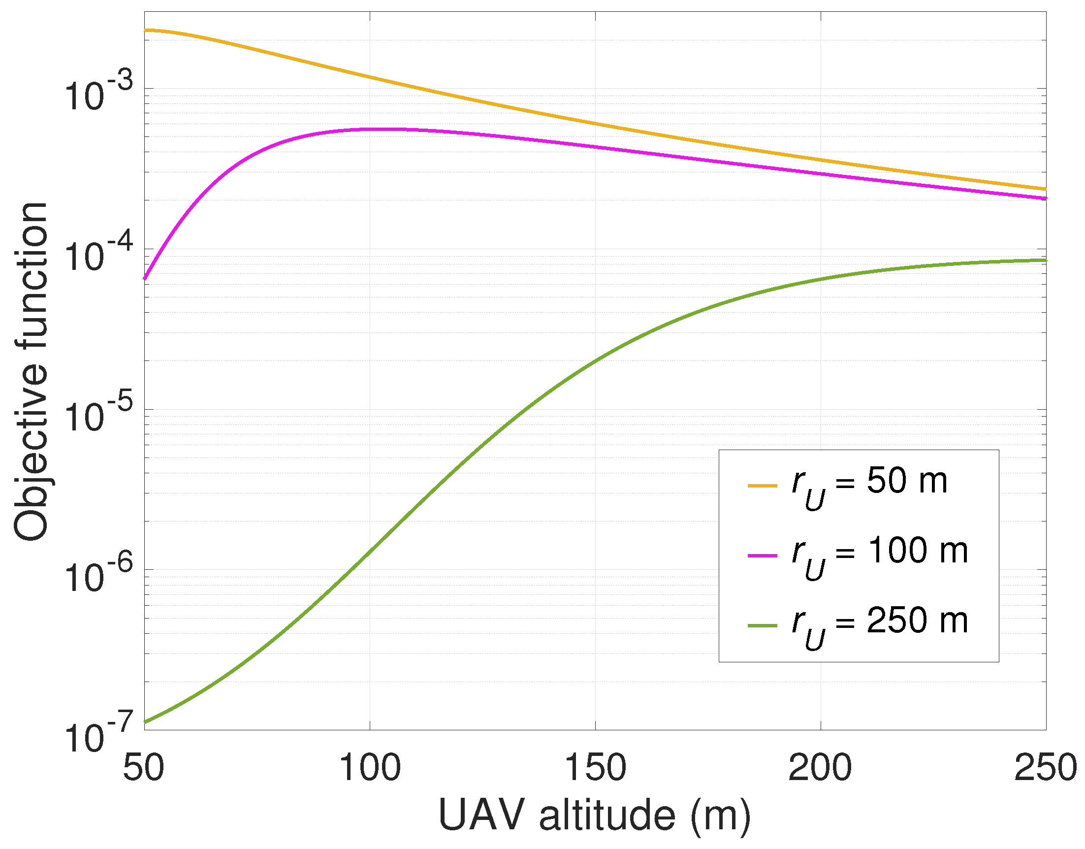
Figure 2 compares the value of the objective function in the problem P 3 h with respect to the UAV altitude (i.e., a variable h) for different horizontal distances of an EHD, i.e., r U = { 50 , 100 , 250 } m. As shown in Figure 2, the objective fucntion depends on the UAV altitude as well as the horizontal distance of an EHD. In specific, when r U = 50 m and r U = 250 m, the objective function is monotonically decreasing and increasing, respectively, as the UAV altitude increases. On the other hand, it is increasing and then decreasing when r U = 100 m.
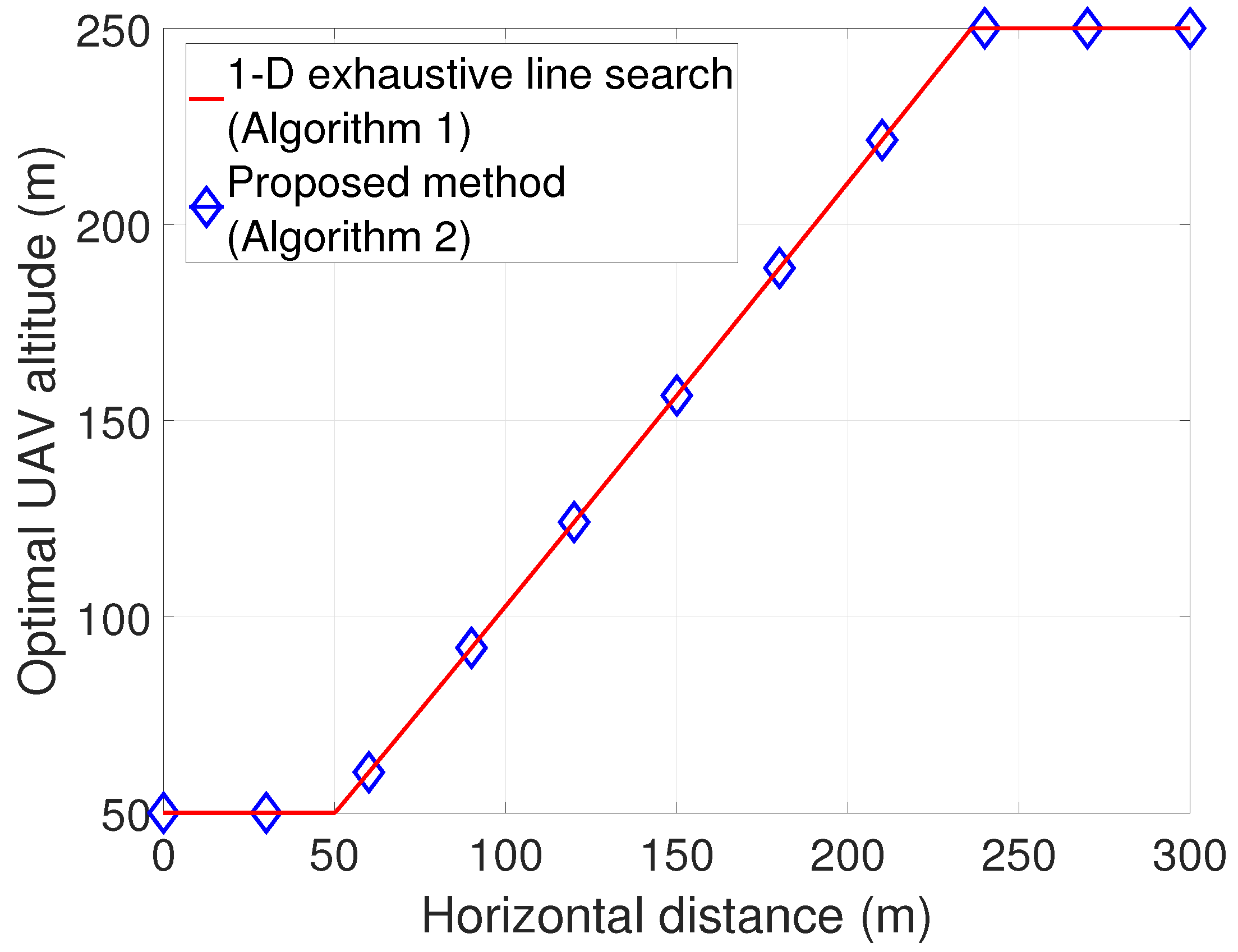
Figure 3 shows the optimal UAV altitude according to the horizontal distance of the EHD, obtained from the 1D exhaustive line search method (Algorithm 1) and proposed method with low complexity (Algorithm 2), respectively. Moreover, Table 2 presents the corresponding average execution time to obtain an optimal value, where we set the same value for the sample grid accuracy Δ and the error tolerance ϵ GS , respectively, i.e., Δ = ϵ GS = 10 5 , in Algorithms 1 and 2 for performance comparison. As expected, the proposed method yields almost identical results to the 1D exhaustive line search method with considerably reduced execution time. Specifically, it is verified that the optimal UAV altitude is the minimum altitude for horizontal distances of up to 50 m, and then it increases from 50 m to 250 m for horizontal distances up to 235 m. Beyond than range, it becomes the maximum altitude. This is because the minimum and maximum altitudes of the UAV are 50 m to 250 m, respectively.

5.2. Performance Evaluation for a Multiple-EHD Scenario

In this subsection, we evaluate our proposed methods in a multiple-EHD scenario. For the Rician fading channel, the u-th EHD’s deterministic LoS component a u is obtained from (4) with d a λ c = 0.5 . To evaluate the average overall charging time, we take the average of 100 independent realizations, varying the energy requirements [ Q u Req ] u = 1 U , horizontal distances [ r u ] u = 1 U , and AoD [ ϕ u ] u = 1 U for each realization. For this purpose, the parameters [ Q u Req ] u = 1 U , [ r u ] u = 1 U , and [ ϕ u ] u = 1 U are uniformly sampled within specified ranges to capture variability. Specifically,the energy requirements [ Q u Req ] u = 1 U are chosen from [ 1 , 10 ] mJ, the horizontal distances [ r u ] u = 1 U are chosen from [ 0 , r max ] u = 1 U where r max [ 100 , 150 ] m, and the angles of departure (AoD) [ ϕ u ] u = 1 U are chosen from [ π / 2 , π / 2 ] radians. Moreover, our proposed methods are evaluated according to the number of EHDs. For performance comparison, we consider the following six methods:
  • A weighted sum-power maximization energy beamforming (W-sum EB) with optimal altitude H Opt .
  • Optimal energy beamforming (EB) for the UAV altitude of H min .
  • Optimal EB for the UAV altitude of H max .
  • Proposed method # 1 —Efficient near-optimal altitude and EB design with low complexity, i.e., Algorithm 4.
  • Proposed method # 2 —Sub-optimal design with weighted-sum EB in a closed-form solution, i.e., Algorithm 5.
  • Optimal design: Optimal EB with optimal altitude, i.e., Algorithm 31.
  • Notably, we consider the widely adopted W-sum EB for a comparative analysis with other methods in terms of energy beamforming performance. The W-sum EB was proposed to maximize the weighted sum-power transferred to the EHDs by an energy beam directed toward the dominant eigenvector of the composite weighted channel gain matrix of the EHDs [1,2]. The optimal altitude for the W-sum EB is obtained using a 1D exhaustive line search method.
To examine the robustness of our proposed methods across various practical scenarios, we consider both Urban and Dense Urban environments for the A2G Rician fading channel model. In this case, the environment-dependent LoS probability parameters are given by ( a 1 , b 1 ) = ( 9.61 , 0.16 ) for the Urban environment and ( a 1 , b 1 ) = ( 12.08 , 0.11 ) for the Dense Urban environment, respectively [8,9]. First, we evaluate the proposed methods in an Urban environment, and then consider a Dense Urban environment.

5.2.1. Performance Evaluation in an Urban Environment

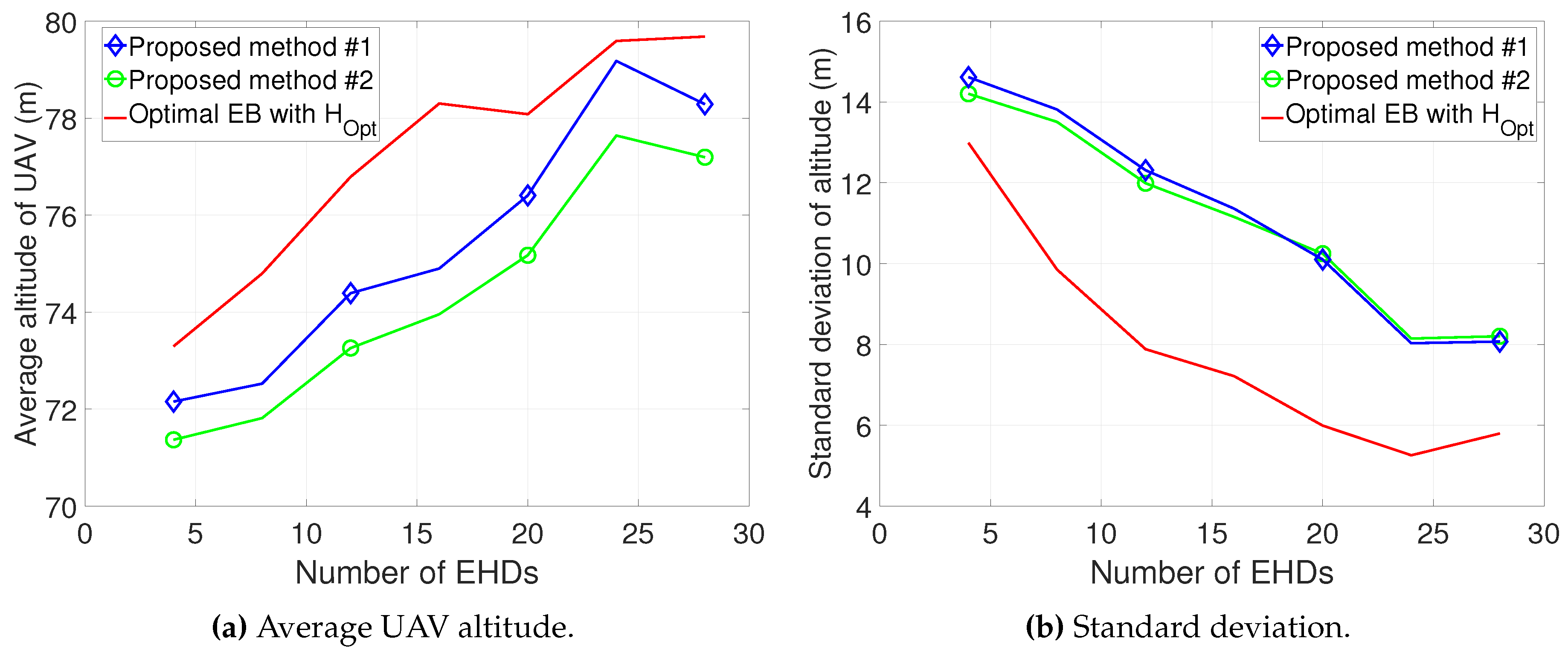
First, we evaluate the various methods when the horizontal distance is 100 m, i.e., r max = 100 m. Figure 4a,b show the average UAV altitude and its standard deviation obtained from proposed method # 1 , proposed method # 2 , and the optimal design. Using proposed method # 1 , the near-optimal altitude of the design is obtained considering the entire range. The performance gap between proposed method # 1 and the optimal design is less than 4 m. The performance gap of proposed method # 2 is larger than that of proposed method # 1 . In addition, the UAV altitude is within [ 70 , 80 ] m, and it increases as the number of EHDs increases. Moreover, Figure 4b demonstrates that the standard deviation is within [ 4 , 15 ] m, and it increases as the number of EHDs increases.
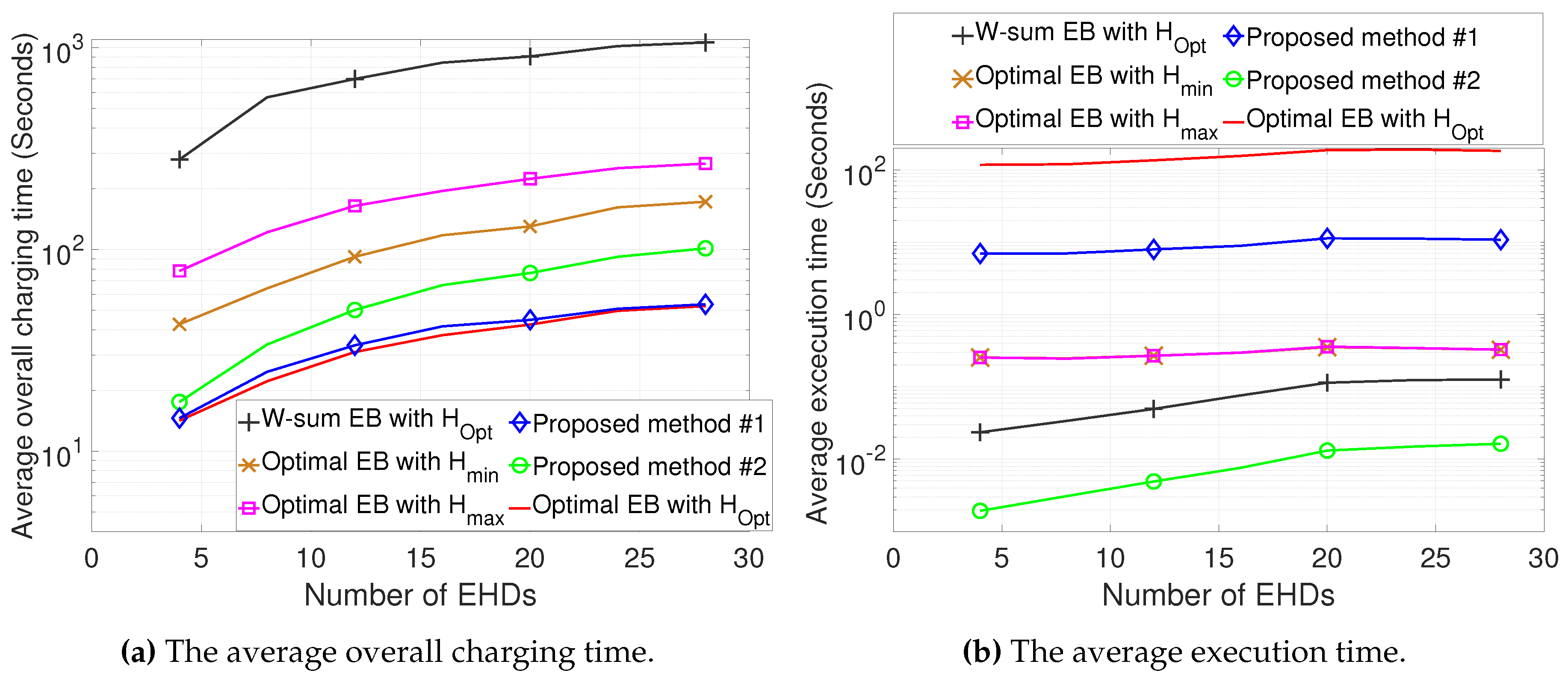
In Figure 5a,b, the average overall charging times and the average execution times of various methods are compared with respect to the number of EHDs. In Figure 5a, the charging time performance for each method is presented, with values of [ 279 , 1062 ] seconds for W-sum EB with H Opt , [ 43 , 173 ] seconds for optimal EB with H min , [ 79 , 267 ] seconds for optimal EB with H max , [ 14.6 , 53.5 ] seconds for proposed method # 1 , [ 17.6 , 101.3 ] seconds for proposed method # 2 , and [ 14.2 , 52.4 ] seconds for the optimal design. As expected, proposed method # 1 outperforms the other methods and achieves a near-optimal charging time over the entire range. The performance gap increases as the number of EHDs increases. Specifically, W-sum EB with H Opt significantly extends the charging time, as the energy beam is not optimized for minimizing charging time. On the other hand, the optimal design yields a large execution time, increasing from 120 seconds to 180 seconds as the number of EHDs increases. By contrast, the execution times range from 7 seconds to 11 seconds for proposed method # 1 , a considerable reduction compared to the optimal design. Meanwhile, proposed method # 2 , which leverages the weighted-sum EB solution in closed form, yields the shortest execution time of below 0.02 seconds while yielding lower charging times than the other methods with H min and H max .
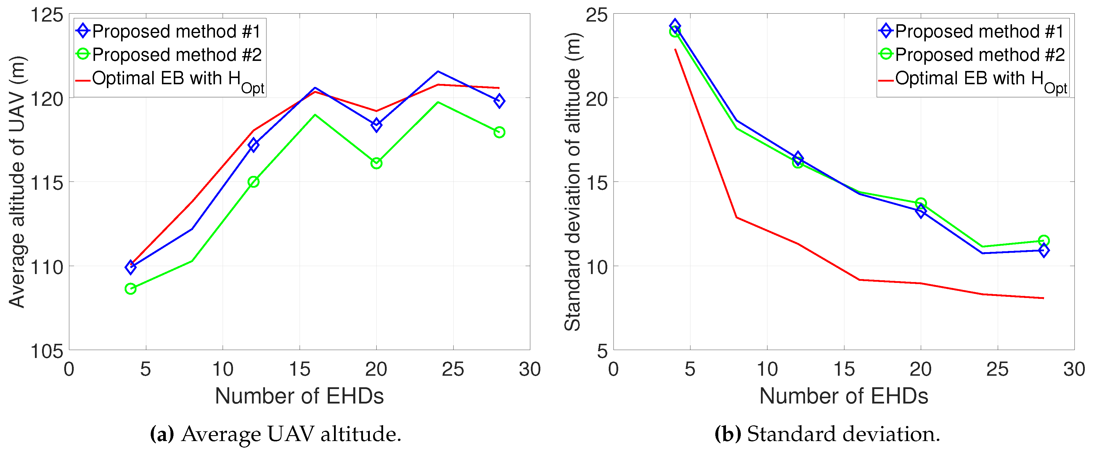
Next, we also evaluate the various methods when the horizontal distance is 150 m, i.e., r max = 150 m. Figure 6a,b show the average UAV altitude and its standard deviation obtained from proposed method # 1 , proposed method # 2 , and the optimal design. Proposed method # 1 achieves near-optimal performance, with the performance gap within 1.5 m. In addition, proposed method # 1 performs comparably to proposed method # 2 , with the performance gap within 2.5 m. As expected, the UAV altitude increases as the number of EHDs increases. The UAV altitude is within [ 108 , 122 ] m, which is higher than the average altitude when r max = 100 m, such as in Figure 4a. In addition, Figure 6b exhibits that the standard deviation is within [ 8 , 25 ] m, which is larger than the standard deviation when r max = 100 m, such as in Figure 4b.
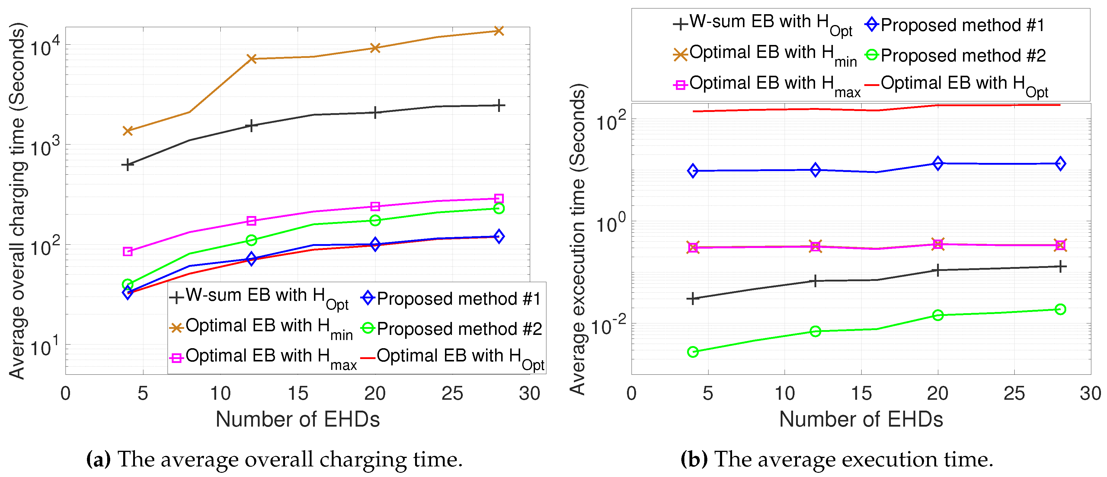
Figure 7a,b show a comparison of the average overall charging time and the average execution time of various methods with respect to the number of EHDs. In Figure 7a, the charging time performance for each method is presented, such as with values of [ 627 , 2461 ] seconds for W-sum EB with H Opt , [ 1370 , 13710 ] seconds for optimal EB with H min , [ 85 , 288 ] seconds for optimal EB with H max , [ 33.1 , 120 ] seconds for proposed method # 1 , [ 39.8 , 229 ] seconds for proposed method # 2 , and [ 32.3 , 119 ] seconds for the optimal design. Proposed method # 1 achieves significantly reduced charging time and near-optimal performance, with a considerable gap compared with other methods as the number of EHDs increases. In particular, there is a substantial increase in the charging time with H min , which is much lower than the optimal altitude, as seen in Figure 6. Compared to the charging time performance when r max = 100 , as seen in Figure 5a, the overall charging time increases when r max = 150 . For example, the charging time for the optimal design increases from [ 14.2 , 52.4 ] to [ 32.3 , 119 ] . Also, it is shown that the conventional EB, i.e., W-sum EB, yields substantial performance degradation compared to the proposed EB. On the other hand, the performance in terms of execution time is similar for r max = 150 (Figure 7b) and r max = 100 (Figure 5b). As expected, proposed method # 1 yields a much shorter execution time compared to the optimal design, and the shortest execution time for all methods is achieved using proposed method # 2 .

5.2.2. Performance Evaluation in a Dense Urban Environment

Next, we evaluate our proposed methods in a Dense Urban environment with r max = 100 m and r max = 150 m, respectively.
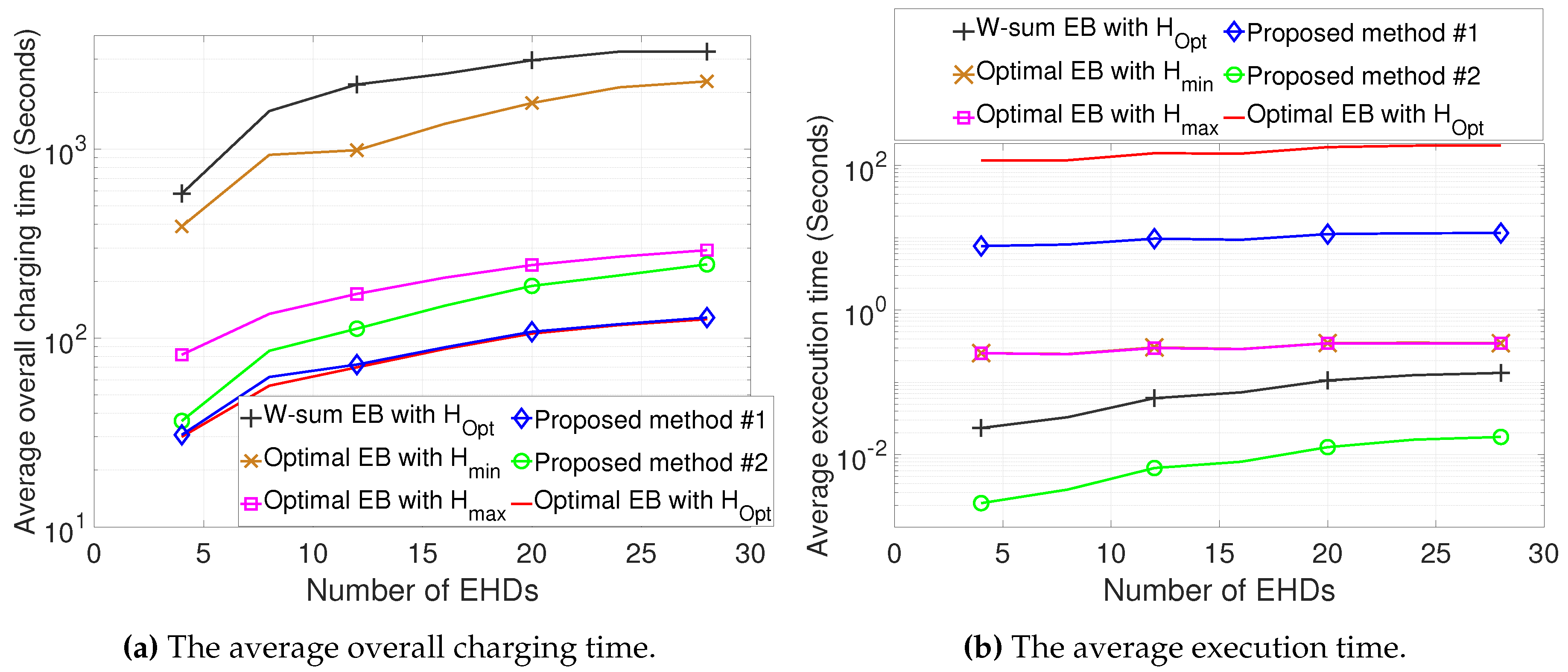
Figure 8a,b exhibit a comparison of the average overall charging time and the average execution time of various methods when r max = 100 m. It is shown that proposed method # 1 achieves a near-optimal charging time over the entire range, while significantly reducing the execution time compared to the optimal design. Moreover, proposed method # 2 achieves the shortest execution time among all methods, while outperforming the conventional methods in terms of overall charging time. However, it results in a longer charging time than proposed method # 1 . In comparison to the charging time performance when r max = 100 in the Urban environment, as shown in Figure 5a, the overall charging time increases in the Dense Urban environment. The reason is that the LoS probability decreases in the Dense Urban environment compared to the Urban environment. On the other hand, Figure 8b shows that the average execution time in the Dense Urban environment demonstrates similar performance to that in the Urban environment, as depicted in Figure 5b. This result confirms that the proposed methods reduce computational complexity compared to other methods, even in the Dense Urban environment.
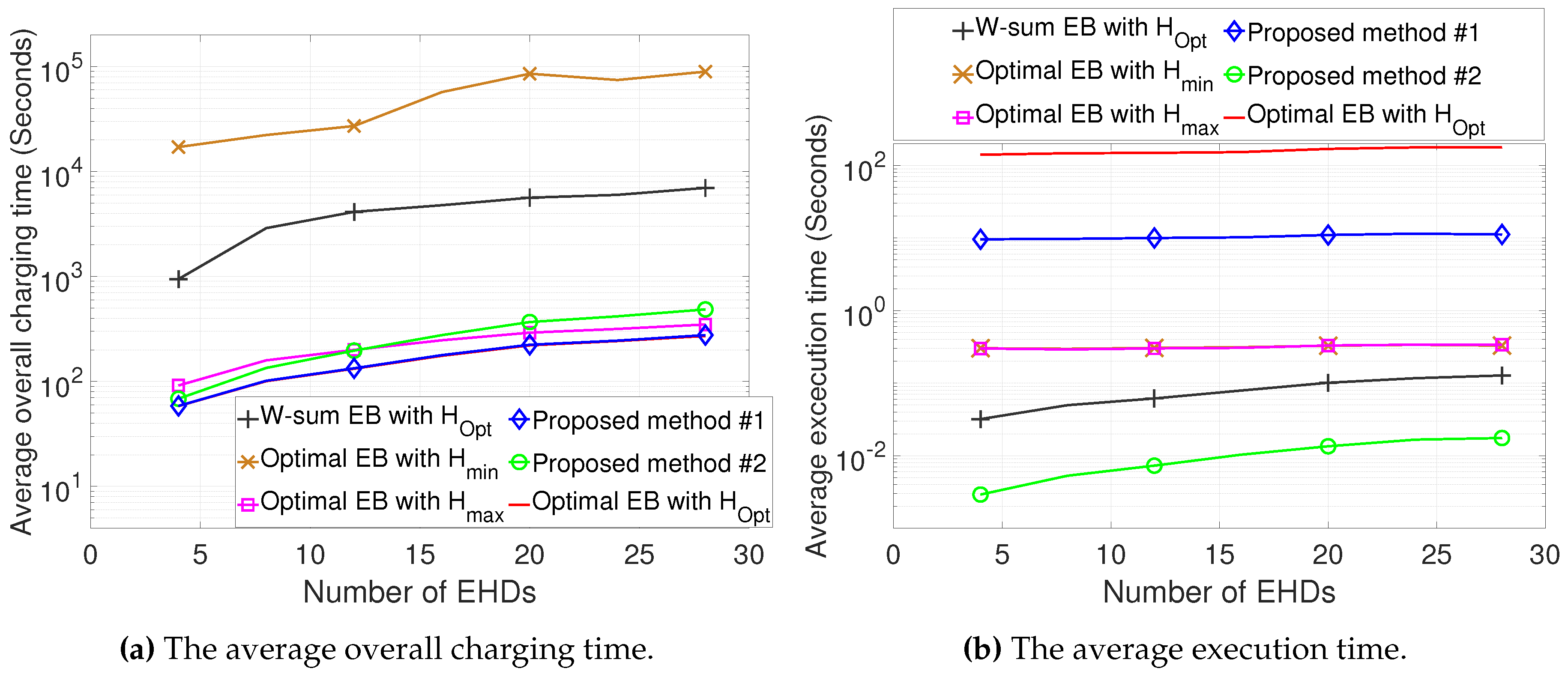
We also evaluate the various methods when r max = 150 m. Proposed method # 1 achieves significantly reduced charging time and yields a much shorter execution time compared to the optimal design. Also, the shortest execution time for all methods is achieved using proposed method # 2 . However, proposed method # 2 is outperformed by the optimal EB with H max in terms of overall charging time when the number of EHDs exceeds 12. Figure 9a also shows that the overall charging time increases in the Dense Urban environment compared to the charging time performance when r max = 150 in the Urban environment, as depicted in Figure 7a. Notably, Figure 9b shows that the average execution time in the Dense Urban environment demonstrates similar performance to that in the Urban environment, that verifies the robustness of the proposed methods in terms of complexity reduction.
These results verify that our proposed methods significantly outperforms conventional methods in terms of overall charging time, while achieving near-optimal performance and substantially reducing execution time across various practical scenarios.

6. Conclusion

In this paper, we propose the joint design of UAV altitude- and channel statistics-based energy beamforming in order to minimize the overall charging time required for all EHDs by considering the A2G Rician fading channel. To solve the formulated problem, which is highly non-convex and non-linear, we first optimized our design for a single EHD by deriving optimal energy beamforming in closed form, thereby developing the low-complexity algorithm to obtain the optimal altitude. Then, considering multiple EHDs, we developed efficient algorithms for the joint design of altitude and energy beamforming based on the dual problem. We further explored two efficient methods with low complexity, yielding a near-optimal solution driven by insights from the design for a single-EHD scenario, as well as a sub-optimal solution by leveraging closed-form weighted-sum energy beamforming. The numerical results demonstrate that compared to conventional methods, the proposed joint design can be used to substantially reduce both the overall charging time as well as the computational complexity. While the overall charging time increases in the Dense Urban environment compared to the Urban environment due to a lower LoS probability, the average execution time remains similar, highlighting the robustness of the proposed methods in terms of complexity reduction.
Although the proposed methods are based on long-term channel statistics, they can be extended to scenarios with perfect CSI by replacing the long-term channel statistics with instantaneous CSI. In addition, the proposed method can be adapted to different channel models, such as Nakagami fading, by redefining statistical expectations and modifying the algorithm with necessary mathematical derivations to incorporate new fading characteristics. Extending the proposed methods to provide a comprehensive analysis of scalability, especially when dealing with large numbers of EHDs in diverse environmental conditions, remains one of our ongoing research topics. Additionally, the joint design of altitude and energy beamforming, taking into account practical factors such as the UAV’s energy consumption, is also part of our ongoing work for future research. Moreover, future work will focus on enhancing the proposed model to adapt to dynamic environmental changes that may impact the UAV’s ability to maintain optimal altitude, ensuring robustness in real-world scenarios
Funding

This work was supported in part by the National Research Foundation of Korea (NRF) grant funded by the Korean Government (MSIT) (RS-2023-00214142) and in part by the MSIT (Ministry of Science and ICT), Korea, under the ICAN (ICT Challenge and Advanced Network of HRD) program (IITP-2024-RS-2022-00156409) supervised by the IITP (Institute of Information

Data Availability Statement

Data are contained within the article.

Conflicts of Interest

The author declares no conflicts of interest.

Appendix A. Proof of Lemma 1

For a fixed h [ H min , H max ] , we obtain an optimal solution for X by solving the following SDP problem:
P 3 X : max X Tr G U ( h ) X s . t . Tr ( X ) P , X 0 .
The problem P 3 X is the well-known maximum eigenvalue problem. Thus, the optimal value and optimal solution for X are obtained in closed form as follows [1,2]:
Tr G U ( h ) X = P Λ max G U ( h )
X = P v max G U ( h ) v max H G U ( h )
where Λ max G U ( h ) and v max G U ( h ) denote the maximum eigenvalue of G u ( h ) and its corresponding eigenvector, respectively.
From (19), G U ( h ) can be rewritten by
G U ( h ) = β 0 d U α U K U K U + 1 a U a U H LoS + 1 K U + 1 I N NLoS
= β 0 d U α U K U + 1 K U a U 2 a ˜ U a ˜ U H LoS + [ a ˜ U , A U ] [ a ˜ U , A U ] H NLoS
= β 0 d U α U K U + 1 K U a U 2 LoS + 1 NLoS a ˜ U a ˜ U H + j = 1 U 1 a ˜ U , j ( a ˜ U , j ) H NLoS ,
where a ˜ U = a U / a U and A U C N × ( N 1 ) are the orthonormal basis of the null space of a ˜ U ; (A4) follows from the fact that I N can be decomposed into I N = [ a ˜ U , A U ] [ a ˜ U , A U ] H . By denoting A U = [ a ˜ U , j ] j = 1 U 1 , (A5) is obtained from ( A U ) H A U = I N 1 .
Since [ a ˜ U , A U ] C N × N is the orthonormal basis of the N-dimensional complex hypersphere, such as for [ a ˜ U , A U ] [ a ˜ U , A U ] H = [ a ˜ U , A U ] H [ a ˜ U , A U ] = I N and K U a U 2 > 0 in (A5), the maximum eigenvalue of G U ( h ) and its corresponding eigenvector are obtained as
Λ max G U ( h ) = β 0 d U α U K U a U 2 + 1 K U + 1 ,
v max G U ( h ) = a ˜ U .
Inserting (A6) and (A7) into (A2) and (A3), respectively, we obtain the optimal solution for the problem P 3 X as follows:
Tr G U ( h ) X = P β 0 d U α U K U a U 2 + 1 K U + 1 ,
X = P a ˜ U a ˜ U H .
As shown in (A9), the optimal covariance matrix of X does not depend on the UAV’s altitude h. Thus, (A9) is the optimal solution for the problem P 3 , regardless of the value of h. This completes the proof.

References

  1. Zhang. R; Ho. C. K. MIMO broadcasting for simultaneous wireless information and power transfer. IEEE Trans. Wireless Commun. 2013, 12, 1989–2001. [Google Scholar] [CrossRef]
  2. Xu. J;Zhang. R. Energy beamforming with one-bit feedback. IEEE Trans. on Signal Process., 2014, 62, 5370–5381. [Google Scholar] [CrossRef]
  3. Kang. J; Choi. J; Choi. W. Multi-User Energy Beamforming for Different Energy Requests. IEEE Wireless Commun. Lett. 2021, 10, 1687–1691. [Google Scholar] [CrossRef]
  4. Monteiro. F. A; López. O. L. A; Alves. H. Massive Wireless Energy Transfer With Statistical CSI Beamforming,” IEEE Journal of Selected Topics in Signal Processing. 2021, 15, 1169–1184.
  5. López. O. L. A; Monteiro. F. A; Alves. H; Zhang. R; Latva-Aho. M. A low-complexity beamforming design for multiuser wireless energy transfer. IEEE Wireless Commun. Lett. 2021, 10, 58–62. [Google Scholar] [CrossRef]
  6. Kang. J. Multi-User Energy Beamforming with Low-Complexity to Reduce Charging Time. The Journal of Korean Institute of Communications and Information Sciences. 2023, 48, 1585–1588. [Google Scholar] [CrossRef]
  7. Kang. J. Channel Statistics based Wireless Energy Transfer with Energy Demand in Rician Fading Channel. The Journal of Korean Institute of Communications and Information Sciences. 2023, 48, 1075–1078. [Google Scholar] [CrossRef]
  8. Al-Hourani. A; Kandeepan. S; Lardner. S. Optimal LAP Altitude for Maximum Coverage. IEEE Wireless Commun. Lett. 2014, 3, 569–572. [Google Scholar] [CrossRef]
  9. Khuwaja. A. A; Chen. Y; Zhao. N; Alouini. M. -S; Dobbins. P. A Survey of Channel Modeling for UAV Communications. IEEE Commun. Surveys & Tutorials. 2018, 20, 2804–2821. [Google Scholar]
  10. Al-Hourani A; Gomez. K. Modeling cellular-to-UAV path-loss for suburban environments,” IEEE Wireless Commun. Lett. 2018, 7, 82–85.
  11. Azari. M. M; Rosas.F; Chen. K. -C; Pollin. S. Ultra Reliable UAV Communication Using Altitude and Cooperation Diversity. IEEE Trans. on Commun. 2018, 66, 330–344. [Google Scholar] [CrossRef]
  12. Shafique. T; Tabassum. H; Hossain. E; End-to-end energy efficiency and reliability of UAV-assisted wireless data ferrying. IEEE Trans. on Commun. 2020, 68, 1822–1837. [Google Scholar] [CrossRef]
  13. Liu. Y; Xiong. K; Lu. Y; Ni. Q; Fan. P; Letaief. K. B. UAV-Aided Wireless Power Transfer and Data Collection in Rician Fading. IEEE J. on Sel. Areas in Commun. 2011, 39, 3097–3113. [Google Scholar]
  14. Lin. S; Zou.Y; Ng. D. W. K. Ergodic Throughput Maximization for RIS-Equipped-UAV-Enabled Wireless Powered Communications With Outdated CSI. IEEE Trans. on Commun. 2024, 72, 3634–3650. [Google Scholar] [CrossRef]
  15. Xie. L; Cao.X; Xu.J; Zhang. R. UAV-Enabled Wireless Power Transfer: A Tutorial Overview. IEEE Trans. on Green Commun. and Net. 2021, 62, 2042–2064. [Google Scholar]
  16. Xu. J; Zeng.Y; Zhang. R. UAV-Enabled Wireless Power Transfer: Trajectory Design and Energy Optimization. IEEE Trans. Wireless Commun. 2018, 17, 5092–5106. [Google Scholar] [CrossRef]
  17. Hu. Y; Yuan. X; Xu.J; Schmeink. A. Optimal 1D Trajectory Design for UAV-Enabled Multiuser Wireless Power Transfer,” IEEE Trans. on Commun. 2019, 67, 5674–5688.
  18. Yuan. X; Yang.T; Hu.Y; Xu.J; Schmeink. A. Trajectory Design for UAV-Enabled Multiuser Wireless Power Transfer With Nonlinear Energy Harvesting. IEEE Trans. Wireless Commun. 2021, 20, 1105–1121. [Google Scholar] [CrossRef]
  19. Gou. X; Sun. Z; Huang. L. UAV-Aided Dual-User Wireless Power Transfer: 3D Trajectory Design and Energy Optimization. Sensors. 2023, 23, 2994. [Google Scholar] [CrossRef]
  20. Yuan. X; Hu.Y; Schmeink. A. Joint Design of UAV Trajectory and Directional Antenna Orientation in UAV-Enabled Wireless Power Transfer Networks. IEEE J. on Sel. Areas in Commun. 2021, 39, 3081–3096. [Google Scholar] [CrossRef]
  21. Yuan. X; Jiang. H; Hu.Y; Schmeink. A. Joint Analog Beamforming and Trajectory Planning for Energy-Efficient UAV-Enabled Nonlinear Wireless Power Transfer. IEEE J. on Sel. Areas in Commun. 2022, 40, 2914–2929. [Google Scholar] [CrossRef]
  22. Mu. J; Sun. Z. Trajectory Design for Multi-UAV-Aided Wireless Power Transfer toward Future Wireless Systems. Sensors, 2022, 22, 6859. [Google Scholar] [CrossRef] [PubMed]
  23. Wang. X; Wu. P; Hu. Y; Cai. X; Song. Q; Chen. H. Joint Trajectories and Resource Allocation Design for Multi-UAV-Assisted Wireless Power Transfer with Nonlinear Energy Harvesting. Drones, 2023, 7, 354. [Google Scholar] [CrossRef]
  24. Che. Y; Zhao. Z; Luo .S; Wu. K; Duan. L; Leung. V. C. M. UAV-Aided Wireless Energy Transfer for Sustaining Internet of Everything in 6G,” Drones, 2023, 7, 328.
  25. Zhang, Y.; Zhao, R.; Mishra, D.; Ng, D.W.K. A Comprehensive Review of Energy-Efficient Techniques for UAV-Assisted Industrial Wireless Networks. Energies, 2024, 17, 4737. [Google Scholar] [CrossRef]
  26. Wang, Z.; Lv, T.; Zeng, J.; Ni, W. Placement and Resource Allocation of Wireless-Powered Multiantenna UAV for Energy-Efficient Multiuser NOMA. IEEE Trans. Wireless Commun. 2022, 21, 8757–8771. [Google Scholar] [CrossRef]
  27. Feng. W.; Tang. J.; Zhao. X.; Zhang. X.; Wang. X.; Wong. K. -K. Hybrid beamforming design and resource allocation for UAV-aided wireless-powered mobile edge computing networks with NOMA. IEEE J. on Sel. Areas in Commun. 2021, 39, 3271–3286. [Google Scholar] [CrossRef]
  28. Yu. H.; Ju. M.; Yang. H. -C. Aggregate Throughput Maximization for UAV-Enabled Relay Networks With Wireless Power Transfer: Joint Trajectory and Power Optimization. IEEE Trans. Veh. Tech. 2024, 73, 8253–8265. [Google Scholar] [CrossRef]
  29. Z. Mao Z.; Hu. F.; Wu. W.; Wu. H.; Shen. X. Joint Distributed Beamforming and Backscattering for UAV-Assisted WPSNs. IEEE Trans. Wireless Commun. 2023, 22, 1510–1522. [Google Scholar] [CrossRef]
  30. S. Lin. S; Zou. Y; Ng. D. W. K. Ergodic Throughput Maximization for RIS-Equipped-UAV-Enabled Wireless Powered Communications With Outdated CSI. IEEE Trans. Commun. 2024, 72, 3634–3650. [Google Scholar] [CrossRef]
  31. Kang. J; Choi. W. Novel Codebook Design for Channel State Information Quantization in MIMO Rician Fading Channels With Limited Feedback. IEEE Trans. on Signal Process., 2021, 69, 2858–2872. [Google Scholar] [CrossRef]
  32. Hagenauer. J; Dolainsky. F; Lutz. E; Papke. W; Schweikert. R. The maritime satellite communication channel–channel model, performanceof modulation and coding. IEEE J. on Sel. Areas in Commun., 1987, 5, 701–713. [Google Scholar] [CrossRef]
  33. Mohsan, S.A.H.; Khan, M.A.; Noor, F.; Ullah, I.; Alsharif, M.H. Towards the Unmanned Aerial Vehicles (UAVs): A Comprehensive Review. Drones. 2022, 6, 147. [Google Scholar] [CrossRef]
  34. Du, S.; Zhong, G.; Wang, F.; Pang, B.; Zhang, H.; Jiao, Q. Safety Risk Modelling and Assessment of Civil Unmanned Aircraft System Operations: A Comprehensive Review. Drones. 2024, 8, 354. [Google Scholar] [CrossRef]
  35. Gao, J.; Pan, W. Research, Analysis, and Improvement of Unmanned Aerial Vehicle Path Planning Algorithms in Urban Ultra-Low Altitude Airspace. Aerospace. 2024, 11, 704. [Google Scholar] [CrossRef]
  36. Boyd. S; Vandenberghe. L. Convex Optimization. Cambridge, U.K.: Cambridge Univ. Press, 2004. [Google Scholar]
  37. Wang. K. -Y; So. A. M. -C; Chang. T. -H; Ma. W. -K; Chi. C. -Y. Outage Constrained Robust Transmit Optimization for Multiuser MISO Downlinks: Tractable Approximations by Conic Optimization IEEE Trans. on Signal Process., 2014, 62, 5690–5705.
  38. Lemon. A; So. A. M. -C; Ye. Y. Low-rank semidefinite programming: Theory and applications. Found. Trends Optim., 2016, 2, 1–156. [Google Scholar] [CrossRef]
1
We set the sample grid accuracy Δ = 0.5 m for the 1D exhaustive line search by considering a practical scenario while avoiding high execution times that make it impossible to use.
Figure 1. Illustration of our system model.
Preprints 137578 g001
Figure 2. Comparison of the objective function for different horizontal distances of the EHD.
Preprints 137578 g002
Figure 3. Comparison of the optimal UAV altitude determined from the 1D exhaustive line search method (Algorithm 1) and the proposed method (Algorithm 2).
Preprints 137578 g003
Figure 4. Average UAV altitude and its standard deviation of various methods when r max = 100 m in an Urban environment.
Preprints 137578 g004
Figure 5. Performance comparison of various methods when r max = 100 m in an Urban environment: (a) the average overall charging time; (b) the average execution time.
Preprints 137578 g005
Figure 6. Average UAV altitude and its standard deviation of various methods when r max = 100 m in an Urban environment.
Preprints 137578 g006
Figure 7. Performance comparison of various methods when r max = 150 m in an Urban environment: (a) the average overall charging time; (b) the average execution time.
Preprints 137578 g007
Figure 8. Performance comparison of various methods when r max = 100 m in a Dense Urban environment: (a) the average overall charging time; (b) the average execution time.
Preprints 137578 g008
Figure 9. Performance comparison of various methods when r max = 150 m in a Dense Urban environment: (a) the average overall charging time; (b) the average execution time.
Preprints 137578 g009
Table 1. Environment for evaluation.
Description Symbol Value
The transmit sum power P 1 W
The path loss at the reference distance β 0 1
The path loss exponents of ground links α 0 3.5
The path loss exponents of aerial links α π 2 2
The Rician factor-related parameters K 0 dB 5 dB
K π 2 dB 15 dB
The minimum altitude of a UAV H min 50 m
The maximum altitude of a UAV H max 250 m
The number of antennas at a UAV N 16
Table 2. Comparison of the average execution time (seconds).
Average execution time (seconds)
1D exhaustive line searching (Algorithm 1) 1
Proposed method (Algorithm 2) 7 × 10 5
Disclaimer/Publisher’s Note: The statements, opinions and data contained in all publications are solely those of the individual author(s) and contributor(s) and not of MDPI and/or the editor(s). MDPI and/or the editor(s) disclaim responsibility for any injury to people or property resulting from any ideas, methods, instructions or products referred to in the content.
Copyright: This open access article is published under a Creative Commons CC BY 4.0 license, which permit the free download, distribution, and reuse, provided that the author and preprint are cited in any reuse.
Prerpints.org logo

Preprints.org is a free preprint server supported by MDPI in Basel, Switzerland.

Subscribe

© 2024 MDPI (Basel, Switzerland) unless otherwise stated