2.2. Rectangular Plate Supported at All Corner Points with the Edges Supported or Free
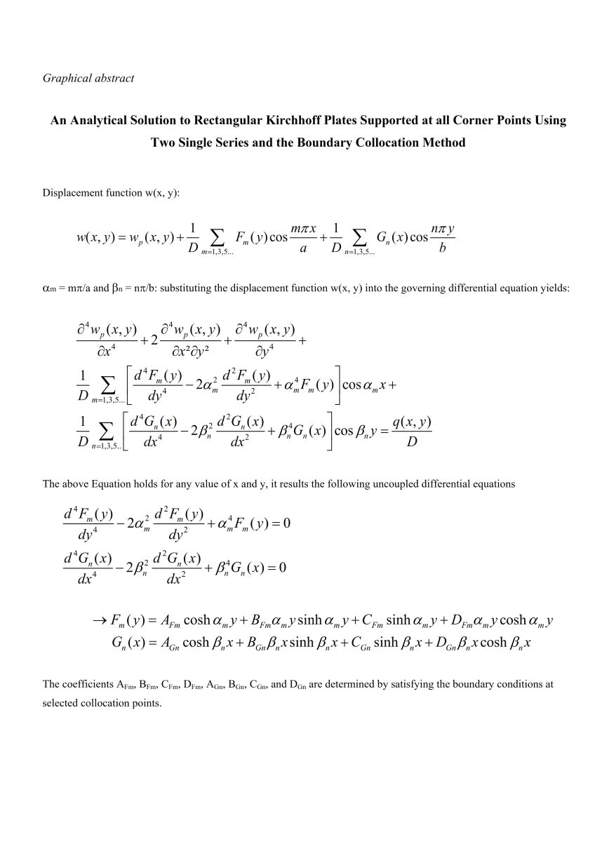
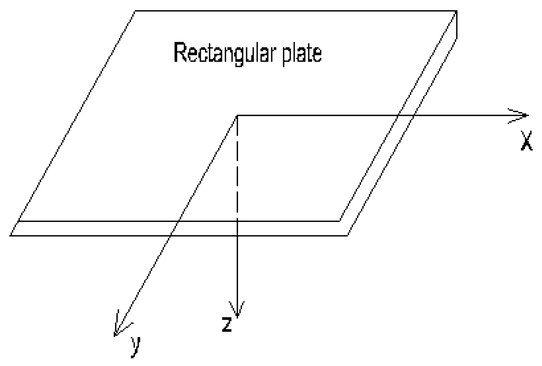
The plate dimensions in x- and y-direction were denoted by a and b, respectively. The rectangular plate was assumed supported at the four corner points whereby the edges had arbitrary support conditions (simply supported, clamped or free). The displacement function was approximated with the sum of a particular solution wp(x,y) to the governing differential Equation (1) and two single series. The choice of two single series is on the one hand due to the possibility to satisfy the boundary conditions along the four edges, inspired from the Lévy solution that involves one single series and the satisfaction of the boundary conditions along two opposite edges (the other edges are simply supported). On the other hand two single series are “geometrically isotropic,” in that the independent variables x and y are treated in the same fair way in terms of accuracy.
Requiring that the particular solution w
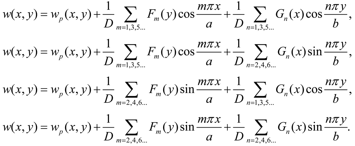
p(x,y) and the single series are zero at the corner points and recalling that the origin of the axes is at the plate center, four possible formulations of the displacement function are as follows
 |
(5a-b) |
Furthermore the term wp(x,y) can be taken as the deflection of a plate strip parallel to the x-axis (or the y-axis), supported at both ends and subjected to the load q(x,y).
Each of the formulation of Equations (5a-d) can generally be considered. In the following the formulation of Equation (5a) is considered. The term w
p(x,y) is a particular solution to Equation (1) and consequently
 |
(6) |
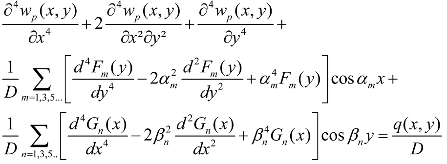
Setting αm = mπ/a and βn = nπ/b and substituting Equation (5a) into (1) yield
 |
(7) |
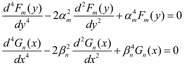
Observing Equation (6) and given that (7) holds for any value of
x and
y, it results the following differential equations
 |
(8a,b) |
Equations (8a, b) further applied in case of Equations (5b-d) for the displacement function. The solutions are given by
 |
(9a,b) |
where the coefficients AFm, BFm, CFm, DFm, AGn, BGn, CGn, and DGn are determined by satisfying the boundary conditions at selected collocation points. The collocation points should be suitably distributed along the edges, and particularly so as to avoid singular matrices. Furthermore, the external running moments and running loads should also be suitably distributed at these points.
It is noted that the collocation points at the edges x = ± a/2 are associated with the series having the function Gn(x) while those at y = ± b/2 are associated with the series having the function Fm(y). Let us consider an approximate solution where the first and second series have M and N terms, respectively. It results in 4M + 4N unknown coefficients. Therefore M collocation points should be considered at each of the edges y = ± b/2 and N collocation points at each of the edges x = ± a/2. Since two boundary conditions are set at each collocation point it results in 4M + 4N equations. So there are as many unknowns as equations.
However in case of symmetry of the structure about an axis and symmetry/anti-symmetry of the loading an appropriate choice can simplify the analysis: here are some useful examples
Symmetrical system about x and y axis and loading symmetrical about x and y axis: Equation (5a) is considered for the displacement whereby only the even parts of Fm(y) and Gn(x) are considered, leading to CFm = Dfm = CGn = DGn = 0. The boundary conditions are then applied at only one fourth of the structure.
Symmetrical system about x and y axis and loading symmetrical about the x axis, i.e., q(x, y) = q(x, -y), and anti-symmetrical about the y axis, i.e., q(x, y) = -q(-x, y): Equation (5c) is considered for the displacement whereby only the odd parts of Gn(x) and the even parts of Fm(y) are considered, leading to AGn = BGn = CFm = Dfm = 0. The boundary conditions are applied at only one fourth of the structure.
Symmetrical system about the x axis and loading symmetrical about the x axis, i.e., q(x, y) = q(x, -y): Equations (5a) or (5c) are considered for the displacement and only the even parts of Fm(y) are considered, leading to CFm = DFm = 0. The boundary conditions are applied at one half of the structure.
Symmetrical system about the y-axis and loading anti-symmetrical about y-axis, i.e., q(x, y) = -q(-x, y): Equations (5c) or (5d) are considered for the displacement and only the odd parts of Gn(x are considered, leading to AGn = BGn = 0. The boundary conditions are applied at one half of the structure.
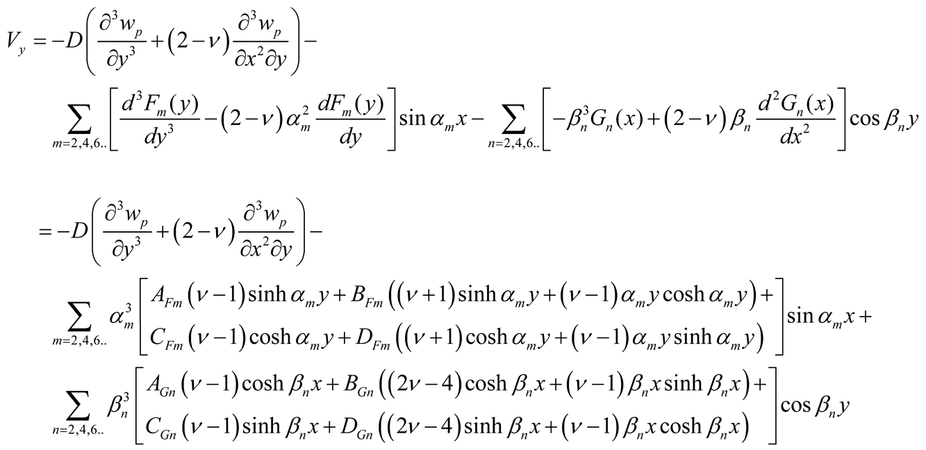
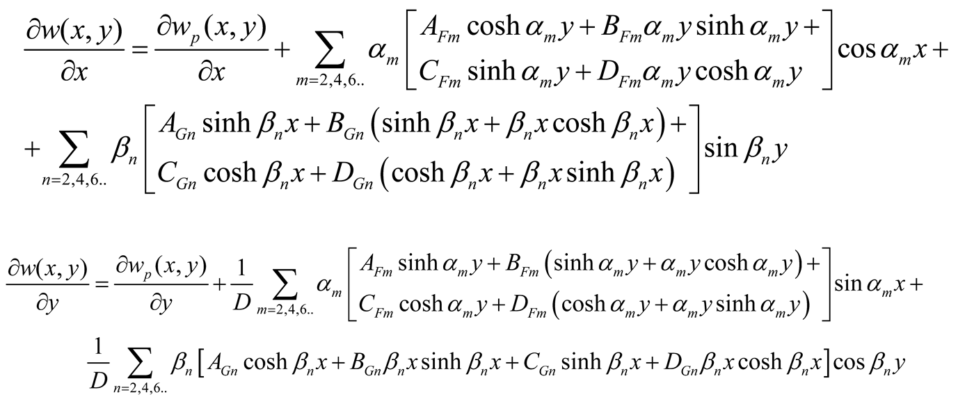
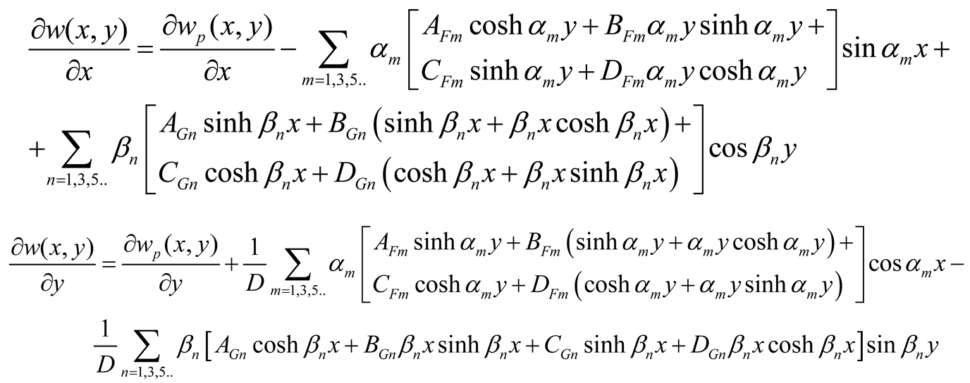
The slopes ∂w/∂x and ∂w/∂y used as boundary conditions are given by
 |
(11c-d) |
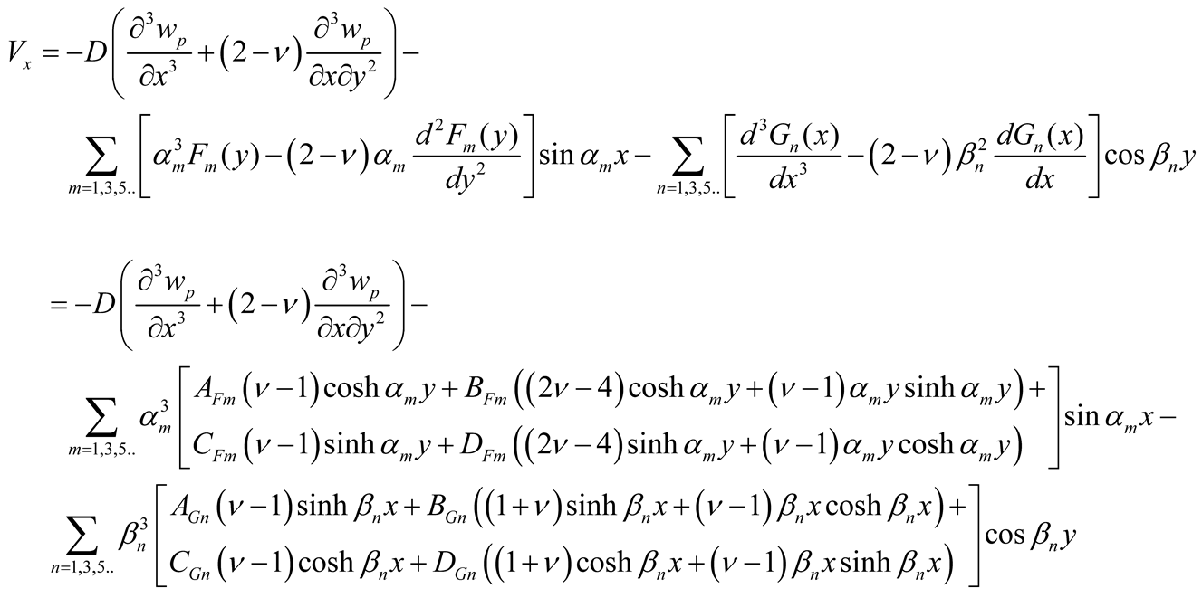
The shear force Q
y used by continuity equations and in case of symmetry are expressed using Equations (3b), (5), and (9a, b), as follows
 |
(11e) |
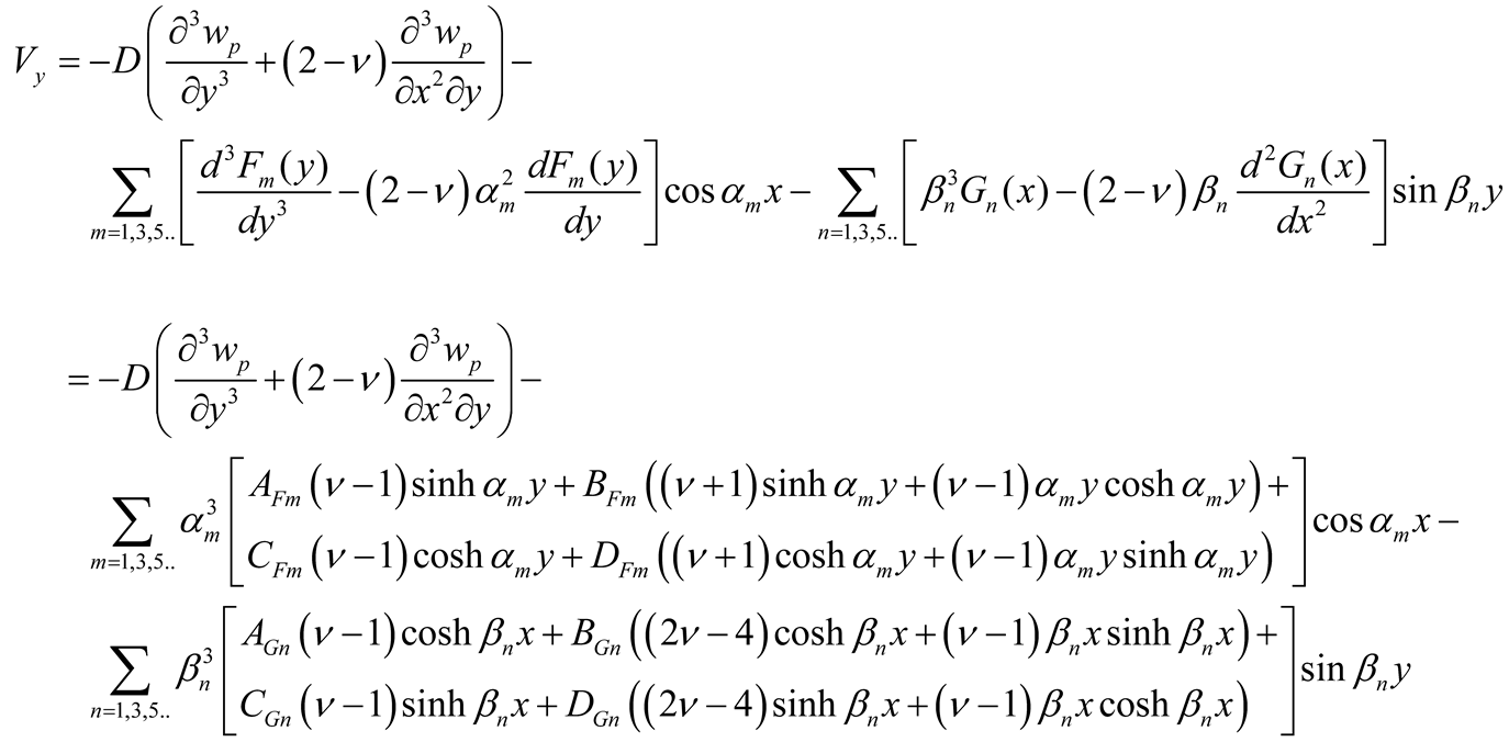
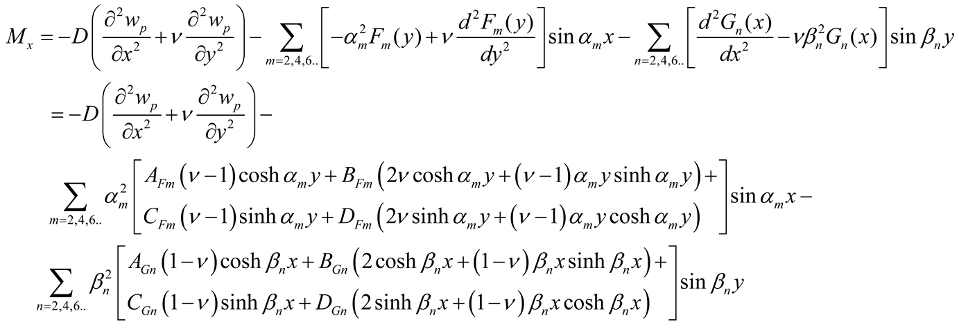
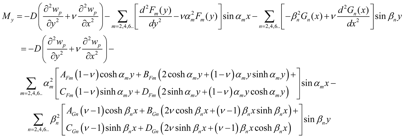
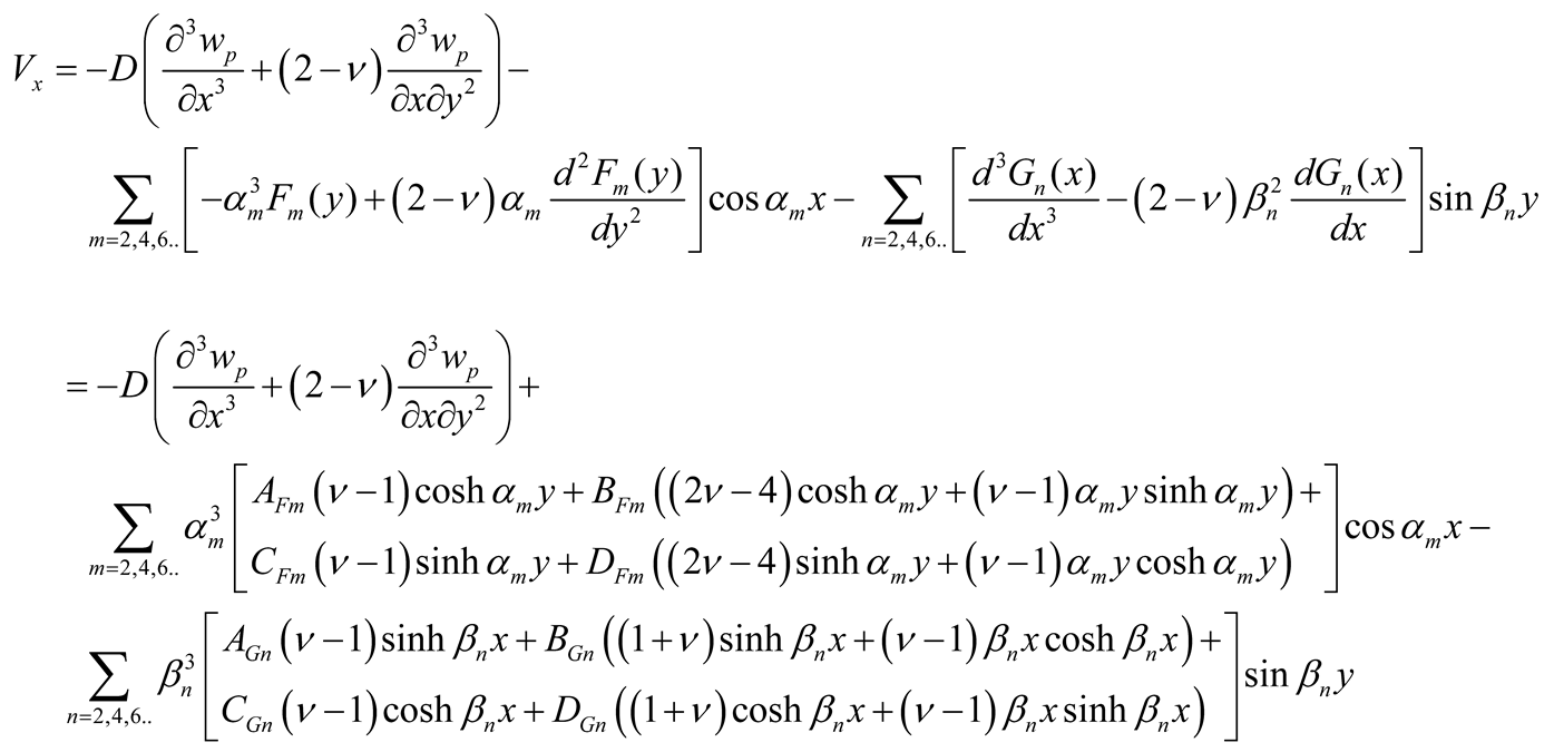
The efforts and deformations above for other formulations of the deflection surface (Equations (5b-d)) are expressed in
Appendix A.
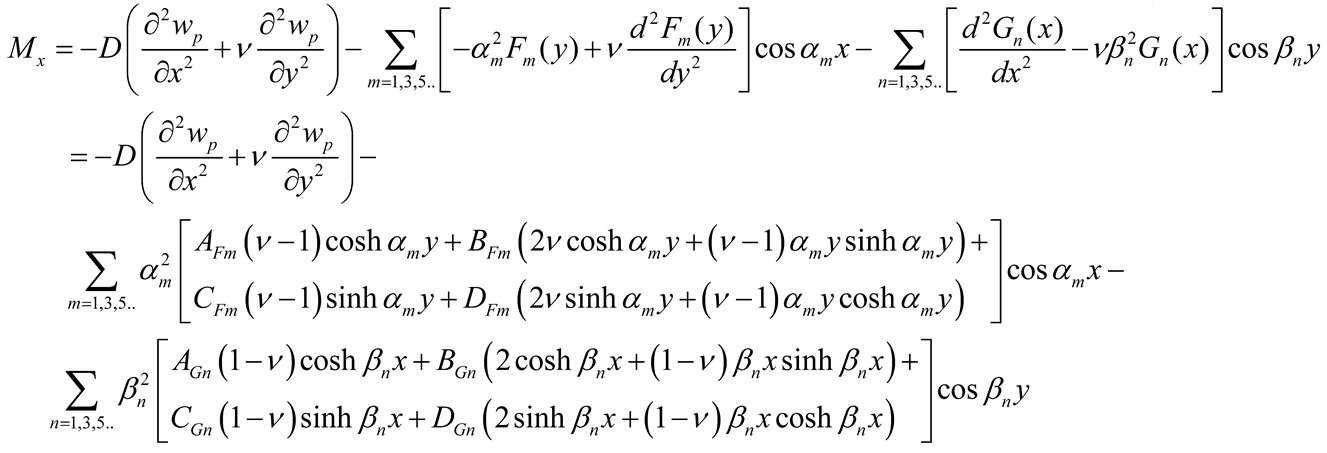
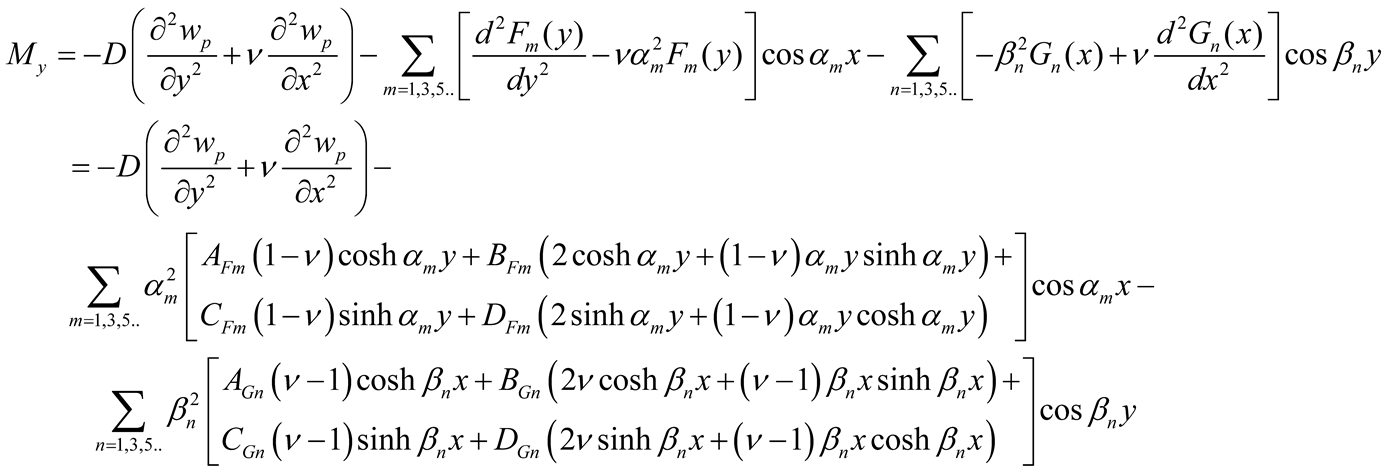
With the determination of the coefficients AFm, BFm, CFm, DFm, AGn, BGn, CGn, and DGn the deflections are calculated using Equations (5) and (9a, b) and the efforts (bending moments Mx, My, and twisting moments Mxy , and effective shear forces Vx and Vy) using Equations (10a-c) and (11a-b).
Analysis of special cases
-
a)
Concentrated force and moment applied at the interior of the plate
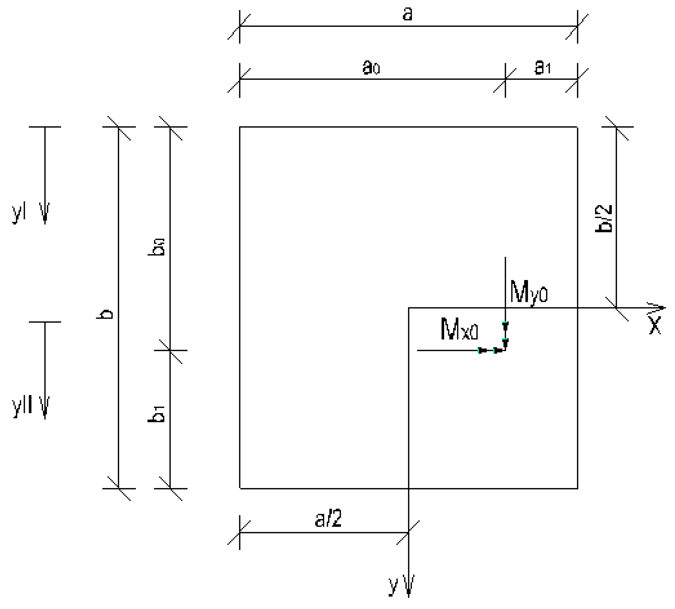
Let an external force P and external concentrated moments Mx0 and My0 be applied at the position (x
0, y
0) as shown in
Figure 2.
Referring to
Figure 2, the deflections defined as before (Equations (5)) are represented with the subscripts I and II for the plate zones –
b/2 ≤
y ≤ –
b/2 +
b0 and –
b/2 +
b0 ≤
y ≤
b/2, respectively, as follows
 |
(12a-b) |
Let the first series of wI and wII have each M terms, and the second series have NI and NII terms, respectively. Therefore, the lines y = –b/2, y = –b/2 + b0, and y = b/2 should be discretized with M nodes, and each of the edges x = ± a/2 of the plate zone I and II should be discretized with NI and NII nodes, respectively. It results in 4M + 4NI unknowns in plate zone I and 4M + 4NII unknowns in plate zone II. The external force P and the moments are distributed to the nodes as follows
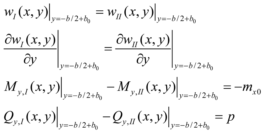
The continuity equations along the line
y = -
b/2 +
b0 express the continuity of the deflection
w and slope ∂w/∂y and the equilibrium of bending moment myy and shear force Qy: these equations are given by
 |
(13a-d) |
Equations (13a-d) are set at each of the M nodes along the line y = -b/2 + b0.
Following number of equations are set for boundary conditions an continuity equations
Plate zone I: 2NI equations at x = -a/2, 2NI equations at x = a/2, and 2M equations at y = -b/2
Plate zone II: 2NII equations at x = -a/2, 2NII equations at x = a/2, and 2M equations at y = b/2
4M continuity equations at y = -b/2 + b0.
So there are as many unknowns as equations.
In case of an external moment My0, the continuity equations are applied along the line x = x0.
It is noted that discrete supports can also be modeled. In this case a node is placed at the position of the support and the continuity equation involving the shear force is replaced with a zero deflection equation.
-
b)
Continuous rectangular plates
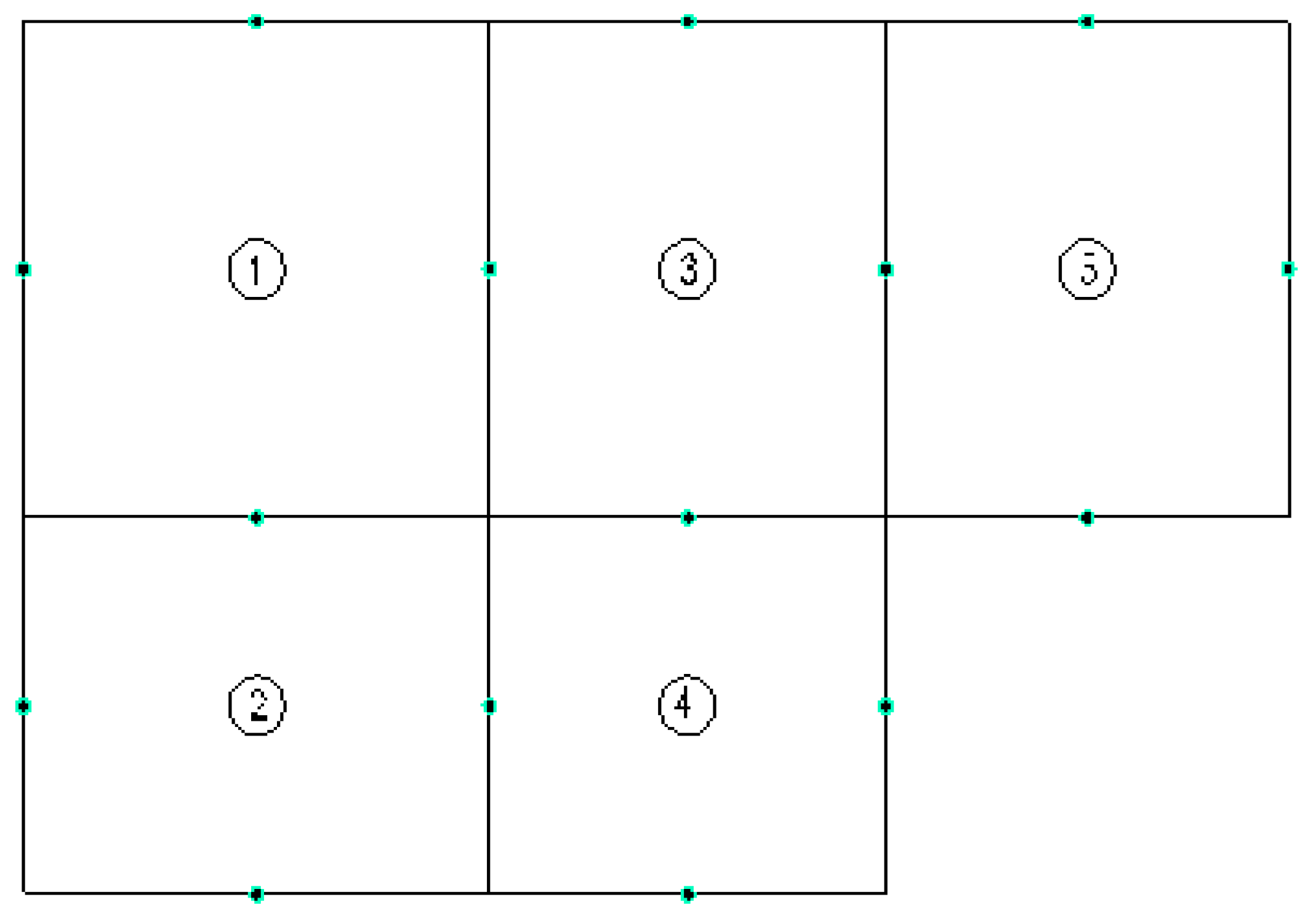
Let us consider the continuous plate represented in
Figure 3. The same deflection approximation is taken in each panel of the plate. For simplification purpose in the current example, only one term of each series is considered and consequently only one collocation point along the sides of each panel. This leads to eight unknowns for each panel, hence to forty unknowns for the five panels of our example.
On the one hand two boundary conditions are applied at each collocation point along the boundary of the plate, leading to twenty equations. On the other hand four continuity equations are applied at the collocation points between two panels, leading to twenty equations. So there are as many unknowns as equations.
Generally the panels aligned in x-direction should have the same number of collocation points in the edges parallel to y-axis, and vice versa.
-
c)
Plate having a free edge clamped at its ends
A plate having a free edge that is clamped at one or at both ends was considered. Recalling that the corner points do not deflect due to the single series (the trigonometric functions are so chosen), the free edge clamped moments due to the series are automatically zero. To fix this, the odd an even numbering of the series was inverted: this led to deflections at the corner points of the plate due to the series and the boundary conditions had to be satisfied accordingly. An example was calculated in Results 3.5, but the results were not satisfactorily. Further research is needed to analyze this case.
