Submitted:
29 October 2024
Posted:
29 October 2024
You are already at the latest version
Abstract
Low-density parity-check (LDPC) codes form part of the IRIG-106 standard and have been successfully deployed for the Telemetry Group version of shaped-offset quadrature phase shift keying (SOQPSK-TG) modulation. Recently, LDPC code solutions have been proposed and optimized for continuous phase modulations (CPMs), including pulse code modulation/frequency modulation (PCM/FM) and the multi-h CPM developed by the Advanced Range TeleMetry program (ARTM CPM). These codes were shown to perform around one dB from the respective channel capacities of these modulations. In this paper, we consider the effect of random puncturing and shortening of these LDPC codes to further improve spectrum efficiency. We perform asymptotic analyses of the ARTM0 code ensembles and present numerical simulation results that affirm the robust decoding performance promised by LDPC codes designed for ARTM CPM.
Keywords:
FEC
; LDPC codes
; telemetry
; avionics
; IRIG
; spectral efficiency
; puncturing
; shortening
; iterative decoding
1. Introduction and Motivation
Low density parity check (LDPC) codes [1] are a family of forward error correction (FEC) block codes that achieve capacity-approaching performance under low-complexity iterative decoding schemes [2,3]. Efficient LDPC encoder designs have given rise to implementations [4,5] that meet the stringent requirements of low-power transmitters and LDPC decoding algorithms are well suited to highly-parallelized decoder structures that facilitate high-throughput FEC [6,7]. LDPC codes have been successfully deployed for aeronautical telemetry systems that employ continuous phase modulations (CPM), specifically SOQPSK-TG [8]. Recent work outlining techniques for the construction of LDPC codes for the remaining two CPM modulation schemes, PCM/FM and ARTM CPM, have demonstrated performance within one dB of channel capacity in numerical simulations [9,10]. While keeping encoding complexity low, these codes represent the current best FEC performance published for ARTM CPM and further optimizing these codes for deployment in aeronautical telemetry systems under bandwidth constraints is an open problem.
One remaining challenge is to develop spectrally efficient LDPC coding schemes for CPM that can adapt to the changing conditions of time-varying channels. Coding schemes that can adaptively respond to changing channel conditions without need for alterations to either their encoder or decoder hardware configurations are known as rate-compatible codes [11]. An efficient means for accomplishing this is to omit sending a portion of the encoded information stream, a process known as puncturing [11,12]. This technique relies on the strength of the code and effect of the puncturing pattern on the decoding algorithm to provide sufficient, though diminished, error correction performance without requiring changes to the decoder [13,14,15]. No a priori information on punctured bits is shared with the decoder prior to transmission, and thus the code rate is increased at the expense of a handicapped decoder. A complementary method, shortening [16], follows much the same logic, but certain code symbols are fixed at the encoder and omitted from transmission where the decoder knows the positions of the shortened bits. This modification can be achieved at the decoder by providing known, perfect a priori information on shortened bits, improving the overall iterative decoding performance at the expense of a decrease in both the code rate and the dimension. Shortening has been shown to improve the performance of LDPC codes [17,18] and an analysis of random shortening was performed in [19].
1.1. Methods and Contributions
In this paper we use random puncturing and shortening to explore the trade-off between coding rate and error control performance for some of the LDPC coding schemes proposed in [9] and [10], enabling the development of spectrally-efficient, rate-compatible coding strategies which require minimal alterations to proven hardware implementations. We follow the notation established in [9] and [10] by using ARTM0, ARTM1, and ARTM2 to refer to PCM/FM, SOQPSK-TG, and ARTM CPM, respectively. We begin by performing asymptotic analyses of the ARTM0 code ensembles. First, we determine the iterative belief propagation (BP) decoding thresholds of randomly punctured ARTM0 LDPC code ensembles on the binary erasure channel (BEC). We then perform an asymptotic minimum distance analysis and show that both the mother code ensembles and the punctured code ensembles are asymptotically good. Moreover, we find that, even though the minimum distance growth rates decrease as the puncturing fraction increases, the gap to the Gilbert-Varshamov bound decreases with puncturing. Taken together, the asymptotic analyses indicate that the ARTM0 LDPC code ensembles are good candidates for random puncturing.
We then present numerical simulation results for various puncturing ratios to create effective coding rates in-between those previously demonstrated. To isolate the effect of modulation on the LDPC encoder-decoder pair, we present results both with and without CPM, highlighting the significant coding gain achieved through optimized design of the LDPC codes with respect to specific modulation schemes. We observe that modulation feedback is responsible for greater than 2 dB of coding gain over the same code without modulation, illustrating the impact of the optimization for that regime. Our results demonstrate that significant gains in spectral efficiency can be obtained for reasonable degradation in FEC performance. For example, with of the symbols omitted from transmission by puncturing, we are able to increase a code with rate to with less than a dB loss at a bit error rate of and with no alterations to the component code or decoder required.
We also provide numerical simulation results for shortened codes showing marked improvements in waterfall performance for codes of sufficient rate and whose blocksizes are of sufficient length. For example, for the ARTM0 mother code with and information length , a coding gain of more than dB can be obtained with random shortening under the CPM modulated scheme. Furthermore, interchanging hardware to allow for shortening and puncturing is not necessary, as both techniques utilize overlapping function blocks with few alterations and may be combined for further flexibility when designing rate-compatible codes.
1.2. Paper Structure
The paper is structured as follows. Section 2 provides the necessary background material, including protograph-based LDPC code construction as well as the code modification techniques we will use, namely puncturing and shortening. In Section 3, we perform asymptotic analyses of the randomly punctured protograph-based ARTM0 ensembles to determine their suitability for puncturing from the perspective of BP and minimum distance. Section 4 and Section 5 provide the system models and numerical simulation results obtained for random puncturing and shortening, respectively. Section 6 then provides a brief description of the hardware considerations before some concluding remarks are provided in Section 7.
2. Background
2.1. Protograph-Based LDPC Codes
An LDPC code, with length n and dimension k, is described as the null space of a parity-check matrix that has rank . We say that an LDPC code is -regular if it has precisely J ones in every column and K ones in every row, otherwise it is called irregular. A protograph [20], with design rate , is a small bipartite graph that connects a set of variable nodes to a set of check nodes by a set of edges. The protograph can be represented by a base biadjacency matrix , where is taken to be the number of edges connecting variable node to check node . The parity-check matrix of a protograph-based LDPC code can be created by replacing each non-zero entry in by a sum of non-overlapping permutation matrices of size and each zero entry by the all-zero matrix.
2.2. Puncturing Linear Codes
A linear code is punctured by removing a set of p columns from its generator matrix, which has the effect of reducing the codeword length from n to . After puncturing a linear code with puncturing fraction , the resulting transmission rate is
where is the rate of the mother (unpunctured) code. The dimension of the code is preserved, and therefore the target rate is achieved, provided no two distinct codewords differ within the p punctured symbols only. This can be achieved, for example, by restricting punctured symbols to the parity-check symbols of a code in systematic form. A code can be punctured randomly or according to a particular pattern. It is assumed that the receiver knows the positions of the punctured symbols, and the decoder estimates both the punctured and transmitted symbols during decoding.
2.3. Shortening Linear Codes
A linear code is shortened by keeping only the codewords from the mother code that have zeros at the postions of the s shortened bits. This is equivalent to removing the corresponding set of s columns from its parity-check matrix. In this paper, we restrict shortening to the k information symbols. Shortening will reduce both the dimension and length of the code. After shortening a linear code with shortening fraction , the resulting transmission rate is
where is the rate of the mother (unshortened) code.
The shortening positions must satisfy the constraint that the shortened parity-check matrix has rank . This can be achieved, for example, by restricting shortened symbols to the k information symbols of a code in systematic form. A code can be shortened randomly or according to a particular pattern. In order to be rate-compatible, we assume that the receiver knows the positions of the shortened symbols and maintains perfect information about those bits in order to estimate the transmitted symbols during decoding.
3. Asymptotic Random Puncturing Analyses of ARTM0 Protographs
In this section, we examine the suitability of the ARTM0 protographs for random puncturing. We remark that specific, finite-length graph liftings were optimized in [9] in order to achieve excellent performance with CPM and a two-stage iterative decoder; however, in this section, we assume asymptotic random liftings for the purpose of analysis of the code ensembles.
3.1. Thresholds of Randomly Punctured ARTM0 Code Ensembles on the BEC
Consider puncturing a length n codeword for transmission over a BEC with erasure probability . We assume that a fixed fraction of the code symbols are punctured, such that the transmitted codeword has length . After transmission, the received vector will contain, on average, erased symbols and correct symbols. The receiver knows the positions of the punctured and erased symbols and proceeds to decode the overall code of length n. From [14], we recall that the BP threshold of a randomly punctured LDPC code ensemble on the BEC with puncturing fraction is given by
where and R are the BP threshold and design rate of the (unpunctured) mother code ensemble, respectively, and is the target rate after puncturing.
Figure 1 shows numerically calculated BP thresholds of the randomly punctured ARTM0 LDPC code ensembles for a variety of puncturing fractions . The mother LDPC code ensemble thresholds are shown by the markers (circle, cross, square, and diamond), with the corresponding punctured thresholds , for various values of and corresponding rate , shown by the lines from a given marker. We observe relatively robust performance under puncturing, particularly for the and ensembles, for which begins closer to capacity. For each ensemble, the threshold values decrease with increasing as increases. Since none of the curves cross, this indicates that random puncturing beyond the rates of the next mother code ensemble are unlikely to provide any advantage in terms of performance. We also note that the rate for which the lines reach a 0 value of threshold is indicative of the maximum rate achievable for random puncturing of the given ARTM0 LDPC code ensemble.
3.2. Minimum Distance Growth Rates of Randomly Punctured ARTM0 Code Ensembles
For , -regular LDPC codes are known to be asymptotically good [21], in the sense that the minimum distance typical of most members of the ensemble is at least as large as , where is called the minimum distance growth rate of the ensemble. The asymptotic spectral shape of a code ensemble, defined as
can be used to test if an ensemble is asymptotically good, where is the normalized Hamming distance, is the block length, and is the ensemble weight enumerator. A technique to calculate for protograph-based LDPC code ensembles was presented in [22]. As a result of the variable node degree optimization of the ARTM0 protographs, we find that the ensembles are asymptotically good, with computed minimum distance growth rates shown in Table 1.
Given the asymptotic spectral shape of an asymptotically good code ensemble, the expected asymptotic spectral shape of the randomly punctured code ensemble can be obtained as [23]
where is the fraction of punctured bits, , and is the binary entropy function. The average weight enumerators used in the formulation of (9) are obtained over all possible p-bit puncturing patterns; therefore, we require to guarantee no rate loss.1
In Figure 2, we present numerical results for the ARTM0 and (b) ensembles obtained using (9) for a variety of puncturing fractions . We note that, in most cases, and, as a consequence, there can be some rate loss, where the true rate is bounded above by . We note, however, that in practice the bits to be punctured would be selected to avoid rate loss by preserving the dimension of the code (semi-randomly or otherwise), and therefore the numerical results obtained in this section are useful indicators of actual punctured code performance.
We observe that, like the mother code ensembles, the punctured ARTM0 LDPC code ensembles are also asymptotically good. Although the minimum distance growth rates must decrease with , the ARTM0 growth rates show robust behavior as the code rate increases, where we observe that the gap to the Gilbert-Varshamov bound decreases with . In particular, the punctured ensemble with has a similar growth rate as the -regular LDPC code ensemble. Taken along with the iterative threshold analysis results from Section 3.1, it appears that the ARTM0 LDPC code ensembles are indeed good candidates for random puncturing.
4. Random Puncturing of ARTM0 LDPC Codes
4.1. System Model
The transmitter model utilized in our system in shown in Figure 3, with function blocks representing the LDPC encoder, interleaver (), puncturing (), CPM modulator, and a module that allows for the insertion of a known symbol sequence referred to as an attached sync marker (ASM) which helps to identify the beginning of each codeword at the receiver. LDPC encoding is performed by multiplying source information sequence of length k with the (systematic, in the case of the ARTM0 codes) code generator matrix of size to form codeword . The resulting codeword is interleaved to form the sequence , on which puncturing is performed. The resulting punctured codeword, , is concatenated with the ASM to form a frame which is modulated by the CPM and sent over the communication channel as the sequence of -ary frames where q is the modulation order. Puncturing () must be performed at the encoder prior to the concatenation of the interleaved codeword and ASM in order to avoid desynchronization during decoding. For random puncturing, if the puncturing pattern and interleaver are sufficiently random, puncturing may be performed before or after interleaving as the distribution of punctured symbols will remain uniformly distributed in either case, while nonrandom puncturing would be constrained to placement after interleaving.
Efficient LDPC encoding algorithms are suitable for many low-power, memory-constrained applications [7]. This is true for the ARTM LDPC codes we have used, which have a quasi-cyclic (QC) structure in which the code’s parity check matrix is an array of sparse repeating units called circulants [4]. The most commonly implemented decoder for LDPC codes is a special case of a more general BP algorithm used for inference on graphical models, known as the sum-product algorithm (SPA) [25]. In this paper, we have used SPA decoding because it provides good performance with soft-input soft-output (SISO) functionality. Efficient hardware implementations of such decoders are numerous and widely adopted [6], including reduced complexity variants such as the min-sum algorithm (MSA) [7].
The receiver model is shown in Figure 4. In this diagram, the values passed between blocks are all real-valued vectors, i.e., log-likelihood ratios (LLRs) [16], that corresponding to the discrete-valued sequence indicated at the input/output of the function blocks. The received sequence is input to the CPM demodulator corresponding to a CPM word along with with no initial a priori information (zero-valued LLRs) on , the binary interleaved and punctured codeword from the LDPC code. After demodulation of a codeword, it is decoded iteratively in a global loop by a pair of CPM and LDPC decoders, which exchange a priori information on through an interleaver and puncturing block , identical to those used for encoding, with corresponding blocks for the inverse deinterleaver and the depuncturer (explained below). For the first global iteration, the results of the CPM demodulator are permuted and used as soft-valued inputs (channel LLRs) for the local LDPC decoder loop by placing the switch in position A. For subsequent global iterations, the signal flow is altered by placing the switch position in B, with the soft output LLRs of the CPM SISO decoder’s update now serving as a priori inputs to the LDPC decoder.
LDPC SPA decoding is performed using the code’s parity-check matrix , a sparse matrix which satisfies the condition . Sparsity keeps the memory and computational requirements tractable for coding schemes with long block lengths that are needed to obtain capacity-approaching performance. The rows of represent the parity check conditions of the code while each column represents a codeword symbol. If a one is present in the k-th column of row j, code symbol k is found in parity check equation . The LDPC decoder performs iterative SPA decoding in the local loop, before passing the output LLRs on as a priori information on to the CPM SISO decoder to start the next global iteration, and so on. We note that in our implementation, the LDPC decoder retains soft values on the punctured symbols within the local loop, this is indicated in Figure 4 by the signal path . The process continues until some stopping criteria is reached (such a ceiling on the allowed number of iterations) and the resulting estimated codeword is passed out of the decoder. Upon completion, hard decisions on are made to complete decoding, where is directly accessible since the encoder is systematic.
Puncturing is performed in the global loop between the CPM SISO decoder and the LDPC decoder. The module removes codeword soft information symbols in accordance with the known puncturing pattern set by the transmitter, resulting in a truncated sequence , as shown in Figure 5. The module intercalates zeros into these same puncturing positions to expand the sequence to its original length before interleaving, in a process referred to as depuncturing. Since the messages passed in the SPA correspond to LLRs, the zero valued LLRs that are placed into the puncturing positions correspond to a bit being equally likely a one or a zero. Finally, we note that at the receiver (Figure 4) the puncturing, depuncturing, interleaving, and deinterleaving all operate on real-vauled vectors.
4.2. Random Puncturing Overhead
The code rate, is the ratio of the number of symbols in the source information sequence, k, to the number of symbols in the transmitted information sequence, n, including parity information. As described in Section 2.2, for a block code of length n, wherein p symbols are punctured, we express the amount of puncturing overhead as the fraction , or as the percentage, . Rate adjustments are made by altering the degree of puncturing overhead. Because puncturing operates on the factor in the denominator of the rate expression (5), the resulting reduction of this quantity increases the code rate. Increasing the code rate results in fewer parity symbols transmitted per unit time, thus increasing throughput or reducing spectrum utilization for any desired target throughput.
For the block code we are implementing, the code rate after puncturing, , is determined solely by the mother (unpunctured) code rate and puncturing overhead, as given in (5). Therefore, the amount of overhead required for any desired code rate is . The codes outlined in [9] are systematic LDPC codes, wherein the source information sequence appears unaltered in the encoded sequence, but in general this is not a requirement because no distinction is made between information and parity symbols in our scheme and puncturing is performed after interleaving. These codes exhibit sufficient regularity such that information symbols and parity symbols are equally protected and punctured symbols are therefore not limited to parity bits in our study.
4.3. Numerical Results
In this section we present the results of our numerical simulations which were performed on the additive white Gaussian noise (AWGN) channel with and without CPM modulation. For the CPM (full system) simulations, we followed [9] and set a maximum of 512 global iterations and a maximum of 1 LDPC decoder iteration with a syndrome-based stopping rule. For the LDPC code only simulations, we use binary phase-shift keying (BPSK) modulation and set a maximum of 100 LDPC decoder iterations and a syndrome-based stopping rule. To obtain an estimate of the average random puncturing performance, we use a different random puncturing pattern per transmitted codeword in our simulations.
4.3.1. Isolated Code, No CPM
In order to isolate the effect puncturing has on decoding performance of the LDPC code alone, we have removed CPM and associated support modules, resulting in the greatly simplified transceiver model shown in Figure 6. With this model, puncturing is performed immediately before encoded information is sent over the communications channel, and depunctured after being received only once. Due to the elimination of the global iterative loop used to exchange information between the CPM and LDPC decoders (c.f., Figure 4), the depunctured information (soft-valued channel LLRs) directly enters the SPA LDPC decoder, where it is iteratively decoded to produce codeword estimate . Simulated error correction performance on the AWGN channel for the ARTM0 code with blocklength and puncturing overhead values of is shown in Figure 7.2 The value is the percentage of puncturing necessary create a code from a mother code and thus represents the intersection between these two approaches.3
Without CPM, SPA decoding is strongly affected by random puncturing, with dB of coding gain lost at a bit error rate (BER) of when moving from to , which represents an effective rate increase from to . Although small values of puncturing are well tolerated, such as shown for , these do not provide a significant increase in code rate (e.g.,, increases to ). It is also observed that puncturing to the next available code rate of by setting results in poor performance, since the decoder cannot compensate for this large . Although it may happen that a code optimized for use with CPM is suboptimal for SPA decoding alone, it is worth nothing that a coding gain of over 7 dB was reported [10] with the modulation scheme in place, outperforming all existing codes which were not optimized for the same modulation schemes.
4.3.2. CPM Included
With CPM included, as shown in the systems presented in Figure 3 and Figure 4, a significant coding gain can be attributed to the global decoder-modulation loop alone. As shown in Figure 8, a coding gain in excess of 2 dB is observed between the systems with and without modulation even without considering puncturing (. This illustrates the chosen LDPC code’s optimization for ARTM modulation and the ability of the SPA decoder to take advantage of information provided by the CPM decoder, working in concert by exchanging successively more accurate a priori information in a doubly-iterative fashion.
For the full system, puncturing has a much more gradual influence on the knee or waterfall region of the resulting BER curve, with an error floor only developing for overheads in excess of . For example, with , corresponding to an increase of the code rate from to , we observed a loss of approximately dB at a BER of in the LDPC only case (Figure 7), whereas in the CPM case we see that this is reduced to approximately dB. At a bit error rate of , the loss remains less than dB. At , with , we see the punctured code still has reasonable performance (unlike no CPM). At this overhead, it performs similarly to the next highest available rate code of indicating that, at this point, it may be preferable to use the next code in the standard for higher rates rather than puncture the lower rate codes. is not achieved until , at which point the performance dramatically degrades (like the case with no CPM). This occurs as a result of the LDPC decoder failing to converge satisfactorily. However, we conjecture that optimized puncturing patterns [13] may be able to reduce this gap. This is the subject of ongoing research.
Our simulation results provide evidence for augmentation of existing codes optimized for specific modulations with rate-compatibility by puncturing. In particular, our study demonstrates that small to moderate can yield attractive trade-offs in rate vs. performance; however, it does not yet appear practical to achieve rates approaching or exceeding the next available ARTM LDPC code with random puncturing alone. From comparison with the non CPM results, the modulation feedback certainly appears to help. Furthermore, the less prominent error-floor features of the modulated version may indicate that more robust puncturing performance is possible for longer block lengths. In this regime, puncturing does not have as strong an impact, since most of the loss in performance due to puncturing comes from finite length effects of the SPA decoder and LDPC code (which itself improves with code length).
In order to better examine the region of interest around the target code, Figure 9 displays the relevant curves across the punctured codes along with the unpunctured modulated ARTM code in terms of normalized symbol energy . The gain between the punctured , code and unpunctured mother code is approximately dB at a BER of , approximately the same as the loss in gain when going from the mother code to punctured , code, highlighting that a window for further improvements is viable. We see, however, that the gap between the punctured code and the mother code has reduced to approximately dB at a BER of , and looks likely to cross at higher SNR since the punctured waterfall is not as steep as the higher rate mother code. Indeed, this error floor behavior continues for . See, for example, the code, which has a significant error floor and loss of over 1dB (and increasing) for BERs lower than when compared to the mother code.
Simulation results presented previously [10] confirm formation of an error floor below a BER of for the mother code, perhaps indicating an underlying weakness in that particular code that is exacerbated by puncturing with or without CPM decoding. At low values of overhead , no error floor is yet apparent at and thus error-floor effects seem to dominate only in high overhead regimes. This gives possible allowance for low overhead random puncturing to be realizable without any further considerations necessary. We also note that low-overhead puncturing where is well tolerated and performance is robust with only a gradual decrease in the slope of the BER curve within the waterfall region. Operation within the waterfall region is nevertheless practical and could serve as an adaptive mechanism when spectral bandwidth is limited and channel conditions are favorable.
5. Random Shortening of ARTM0 LDPC Codes
As described in Section 2.3, shortening is a complementary technique to puncturing wherein codes of shorter length and lower rate can be constructed from a higher-rate mother code. To accomplish this in our proposed rate-compatible architecture, infinite reliabilities are assigned for the selected (shortened) information bits whose positions are known to both the transmitter and receiver, removing those bits from the resulting codeword. This corresponds to the removal of the matching information columns from the LDPC code’s parity-check matrix, reducing the code rate as given in (6).
5.1. Model and Method
The system model for shortening is nearly identical to that provided in Section 4.1 for puncturing (i.e., Figure 3 and Figure 4), with the only alteration being to the function blocks and and the inclusion of a function block that is used to shorten the information sequence. In the shortening transmitter model (Figure 10), module forces s bits in the input sequence, , to zero, producing shortened sequence which serves as input to the LDPC encoder. Since the encoder is systematic, the corresponding code symbols will also be zero, as prescribed by our shortening model. Note also that this excludes any parity bits from being shortened (fixed to zero) and effectively removes the corresponding rows from the generator matrix utilized by the LDPC encoder.
In the shortening transmitter and receiver models, operates in a similar way to puncturing, but now only removes the known (shortened) information bits of the code (after interleaving). With puncturing, operates to insert zero-valued LLRs, corresponding to an equal probability of a bit being a zero or one since this information is not shared between the transmitter and receiver prior to transmission (but must still be estimated). However, in the shortening receiver model (see Figure 11), module operates by inserting infinite valued LLRs (practically, a very large positive value) in the exact positions corresponding to the shortening pattern selected by the transmitter. This ensures the shortened symbols are fixed to zero, removing them from the parity check equations performed by the LDPC decoder. Similar to puncturing, we will consider various values of shortening overhead , as defined in Section 2.3, or as a percentage .
5.2. Numerical Results
Simulation results were obtained with the same experimental setup used for random puncturing, as described in Section 4.3, with the exception that a different random shortening pattern is selected per transmitted codeword. Both the rate and block length of the mother code play an important role in the performance of ARTM0 codes under random shortening. If we first consider the performance of the shortened , and codes in terms of symbol energy (Figure 12), we observe an improvement in performance with increasing (and lowering rate ) as expected. However, when we adjust for rate and consider the same examples in terms of information bit energy (Figure 13), no gain is observed by shortening the mother code with , and an observed loss as we further increase to . However, with the higher rate mother code, the larger gains observed in from Figure 12 do translate to improvements in terms of . We observe that each step increases in shortening from to produces an approximate gain of about dB per step at a BER of . We remark that the with (not shown), the shortened code rate is , but the performance falls short of the mother mother code. Similar results to those of the code are obtained for the shortened codes, where gains are observed in terms of , but not when correcting for rate with . These results indicate the short () ARTM0 block codes of low rate are less amenable to shortening, making rate-matching difficult for lower-rate mother codes, but possible with the higher rate mother codes. As with the random puncturing, it is possible that specific shortening patterns could yield gains over random shortening.
If larger block sizes are considered, shortening produces better results in terms of overall BER performance, especially for higher-rate codes. As shown in Figure 14, a coding gain of dB is observed in the waterfall region of the code with information block size and whereas a gain of approximately dB was observed in the code with of the same rate and the same amount ofshortening. This implies that longer length block codes may be more amenable to random shortening, making rate-matching easier to accomplish with acceptable losses in performance.
For both block sizes considered, the code with mother rate shortened by produces a code of rate , providing a convenient rate-compatible option for framing and hardware implementation. For the mother code, moving to a larger block size of does produce a slight gain at within a narrow portion of the waterfall region, which was not observed for random shortening of the corresponding code. Even with the longer blocklengths, random shortening may have a negative impact on performance when adjusting for rate.
5.3. Puncturing vs. Shortening
Finally, we briefly discuss the trade-offs observed by puncturing a lower rate ARTM0 code verus shortening a higher rate ARTM0 code. Figure 15 shows the results obtained for random puncturing of the , , code with and (solid lines) alongside those obtained for random shortening of the , , code with and (dot-dash lines) with a goal of hitting target rates of approximately (blue) and (red). We observe that for rates close to the lower rate ARTM0 code, puncturing offers the best performance whereas for the higher rates between the mother codes, it may be preferable to shorten the higher rate code. For example, to obtain we find that it is a better strategy to puncture the mother code; whereas for a target rate of we find that it is better to shorten the mother code.
6. Hardware Considerations
Random puncturing and shortening may be implemented by the insertion of a switch in the registers that serve as buffers to the inputs of each module in the signal chain. At random intervals chosen by the overhead parameters, block length, and system bus speed, the switch is placed in the high impedance position for one clock cycle. Depuncturing/deshortening is accomplished by insertion of a random delay, at which point a zero-value (puncturing) or infinite value (shortening) is inserted into the buffer. Although this introduces additional latency, because all modules operate blockwise, it is possible to perform both puncturing and depuncturing in parallel.
Thus when operating in a low-overhead regime as our results suggest, random puncturing and shortening offer robust rate-compatible performance with no changes to the submodules of Figure 3 and Figure 4. Since no substantive hardware alterations are required, this allows for new operational modes at little expense in terms of latency and memory. However, it is worth noting that because the LDPC SPA decoder still operates on the full depunctured/deshortened sequence, SPA decoding computational complexity will remain largely unchanged.
7. Conclusions
In this paper we have laid the groundwork for the construction of rate-compatible LDPC codes for IRIG-106 waveforms by the use of random puncturing and shortening. Our initial results show robust performance with codes designed for deployment with ARTM CPM modulation and open promising avenues for further improvement. Such systems would allow for the adaptive allocation of bandwidth in response to changing demand or channel conditions without requiring significant changes to the underlying encoding and decoding hardware and thus represent a low-complexity, low-cost implementation option. Furthermore, because puncturing is a type of erasure channel, it is easily modeled and those results are readily extended to other channel models, reducing design iteration schedules.
By isolating the LDPC encoder and decoder, we were able to show the considerable coding gain afforded by the CPM-LDPC decoder loop, reinforcing that codes designed specifically for these modulations are better optimized than codes that do not consider modulation during design. Though in neither case did we observe that random puncturing alone achieves the same performance as a code designed for that specific target rate, the gap is much more tractable with modulation, having a span of dB, whereas without modulation the required overhead elicits an impractical error floor. Shortening codes with modulation is a viable method for producing rates in-between the mother code rates, but the technique works best for shortening the highest rate code with diminishing returns for lower-rate mother codes.
In future work, other codes, including those of different rates and lengths, will be considered in order to better understand the interplay between the strength of the code and its resilience to puncturing and shortening under CPM. Modulation appears to be no impediment to the implementation of puncturing, with perturbations in the codeword’s structure most strongly felt within the inner LDPC decoding loop of Figure 4. Because the code we are using in our model is designed specifically to take advantage of information from the CPM decoder, further work should examine the selection of puncturing patterns which least disturb this feedback mechanism in order to preserve its portion of the total coding gain, which was observed to be in excess of 2 dB. Furthermore, analytical results from density evolution on the BEC indicate not only that preferential puncturing patterns exist, but that catastrophic patterns exist which yield extremely low decoding thresholds and should be avoided [14]. This knowledge will help inform the selection of nonrandom or quasi-random puncturing patterns which may bridge the gap between the punctured and mother codes seen in our present analysis. It will also better describe the limits of the code design procedure and may offer new avenues for optimization.
Author Contributions
Investigation of techniques and system simulation, original draft preparation, A.D.C.; Asymptotic analyses, writing and editing, D.G.M.M.; Construction of ARTM codes and development of the iterative CPM decoding framework, E.P. All authors have read and agreed to the published version of this manuscript.
Funding
This material is based upon work supported by the National Science Foundation under Grant Nos. CNS-2148358 and HRD-1914635.
Acknowledgments
This article is a revised and expanded version of a paper entitled “Spectrally Efficient LDPC Codes for IRIG-106 Waveforms via Random Puncturing,” which was presented at the 2024 International Conference on Telemetry, Glendale, AZ, Oct. 2024.
Conflicts of Interest
The authors declare no conflicts of interest.
Abbreviations
The following abbreviations are used in this manuscript:
| ARTM | Advanced Range TeleMetry |
| ASM | Attached Sync Marker |
| AWGN | Additive White Gaussian Noise |
| BEC | Binary Erasure Channel |
| BER | Bit Error Rate |
| BP | Belief Propagation |
| BPSK | Binary Phase-shift Keying |
| CPM | Continuous Phase Modulation |
| FEC | Forward Error Correction |
| FM | Frequency Modulation |
| LDPC | Low-Density Parity-Check |
| LLR | Log-likelihood Ratio |
| MSA | Min-sum Algorithm |
| PCM | Pulse Code Modulation |
| QC | Quasi-cyclic |
| SISO | Soft-in, Soft-out |
| SOQPSK-TG | Telemetry Group version of Shaped-Offset Quadrature Phase Shift Keying |
| SPA | Sum-product Algorithm |
References
- Gallager, R. Low-density parity-check codes. IRE Trans. on Info. Theory 1962, 8. [Google Scholar] [CrossRef]
- MacKay, D. J. C. Near Shannon Limit Performance of Low Density Parity Check Codes. Elect. Letters 1997, 33. [Google Scholar] [CrossRef]
- T. J. Richardson and R. L., Urbanke. The Capacity of Low-Density Parity-Check Codes Under Message-Passing Decoding. IEEE Trans. on Info. Theory 2001, 47. [Google Scholar]
- Z. Li, et al., Efficient encoding of quasi-cyclic low-density parity-check codes. IEEE Trans. on Comms. 2006; 54.
- T. Richardson and H. Jin, “LDPC encoding methods and apparatus,” U.S. Patent No. 7,346,832 (Assigned to Qualcomm Inc.), 2008.
- X-Y Hu, et al., “Efficient implementations of the sum-product algorithm for decoding LDPC codes,” Proc. IEEE Global Telecomms. Conf., vol. 2, cat. no. 01CH37270, 2001.
- C-C. Cheng. A fully parallel LDPC decoder architecture using probabilistic min-sum algorithm for high-throughput applications. IEEE Trans. on Circ. and Sys. I: Reg. Papers 2014, 61. [CrossRef]
- Range Commanders Council Telemetry Group, Range Commanders Council, “IRIG Standard 106-23,” Telemetry Standards, White Sands Missile Range, New Mexico, 2024 (irig106.org).
- E. Perrins, “LDPC codes for IRIG-106 waveforms: Part I–Code Design,” Proc. Int. Telemetering Conf., (Las Vegas, NV), Oct. 2023.
- E. Perrins, “LDPC codes for IRIG-106 waveforms: Part II–Receiver Design,” Proc. Int. Telemetering Conf., (Las Vegas, NV), Oct. 2023.
- J. Hagenauer, “Rate-compatible punctured convolutional codes (RCPC codes) and their applications,” IEEE Trans. on Comms., vol. 36 no. 4, 1988.
- J. Ha, J. Kim, and S. W. McLaughlin. Rate-compatible puncturing of low-density parity-check codes. IEEE Trans. on Info. Theory 2004, 50. [Google Scholar]
- H. Zhou, D. G. M. Mitchell, N. Goertz. Robust Rate-Compatible Punctured LDPC Convolutional Codes. IEEE Trans. on Comms. 2013, 61. [Google Scholar] [CrossRef]
- D. G. M. Mitchell, M. Lentmaier, A. Pusane, and D. J. Costello Jr., “Randomly Punctured LDPC Codes,” IEEE Journ. on Selected Areas in Comms., vol. 34 no. 2, Feb. 2016.
- A. D. Cummins, D. G. M. Mitchell, and E. Perrins, “Spectrally Efficient LDPC Codes for IRIG-106 Waveforms via Random Puncturing,” Proc. Int. Telemetering Conf., (Glendale, AZ), Oct. 2024.
- S. Lin and D. J. Costello, Jr., “Error Control Coding: Fundamentals and Applications,” Prentice Hall, 2004.
- T. Tian and C. R. Jones, “Construction of rate-compatible LDPC codes utilizing information shortening and parity puncturing,” EURASIP J. Wirel. Commun. Netw., vol. 2005, no. 5, pp. 789-795, Oct. 2005.
- S. -R. Kim and D. -J. Shin, “Lowering Error Floors of Systematic LDPC Codes Using Data Shortening,” IEEE Communications Letters, vol. 17, no. 12, pp. 2348-2351, Dec. 2013.
- A. Suls, Y. Lefevre, J. Van Hecke, M. Guenach and M. Moeneclaey, “Error Performance Prediction of Randomly Shortened and Punctured LDPC Codes,” IEEE Communications Letters, vol. 23, no. 4, pp. 560-563, April 2019.
- J. Thorpe, “Low-density parity-check (LDPC) codes constructed from protographs,” Jet Propulsion Laboratory, Pasadena, CA, INP Progress Report 42-154, Aug. 2003.
- R. G. Gallager, “Low-density parity-check codes,” Ph.D. dissertation, Massachusetts Institute of Technology, Cambridge, MA, 1963.
- D. Divsalar, S. Dolinar, C. Jones, and K. Andrews, “Capacity-approaching protograph codes,” IEEE J. Sel. Areas Commun., vol. 27, no. 6, pp. 876–888, Aug. 2009.
- E. C. Boyle and R. J. McEliece, “Asymptotic weight enumerators of randomly punctured, expurgated and shortened code ensembles,” in Proc. Forty-Sixth Annual Allerton Conference, Monticello, IL, Sept. 2008.
- C.-H. Hsu and A. Anastasopoulos, “Capacity achieving LDPC codes through puncturing,” IEEE Trans. Inf. Theory, vol. 54, no. 10, pp. 4698–4706, Oct. 2008.
- F. Kschischang, B. J. Frey, and H. A. Loeliger. Factor graphs and the sum-product algorithm. IEEE Trans. on Info. Theory 2001, 47. [Google Scholar] [CrossRef]
| 1 | For the rate of the ensemble can be written as , where . Bounds on and conditions such that were given for -regular LDPC code ensembles in [24]. |
| 2 | The , , ARTM0 code is constructed from the lifted base matrix [9]. |
| 3 | In this paper, rates are rounded to three decimal places. |
Figure 1.
BEC BP thresholds of randomly punctured ARTM0 LDPC code ensembles for a variety of puncturing fractions .
Figure 1.
BEC BP thresholds of randomly punctured ARTM0 LDPC code ensembles for a variety of puncturing fractions .
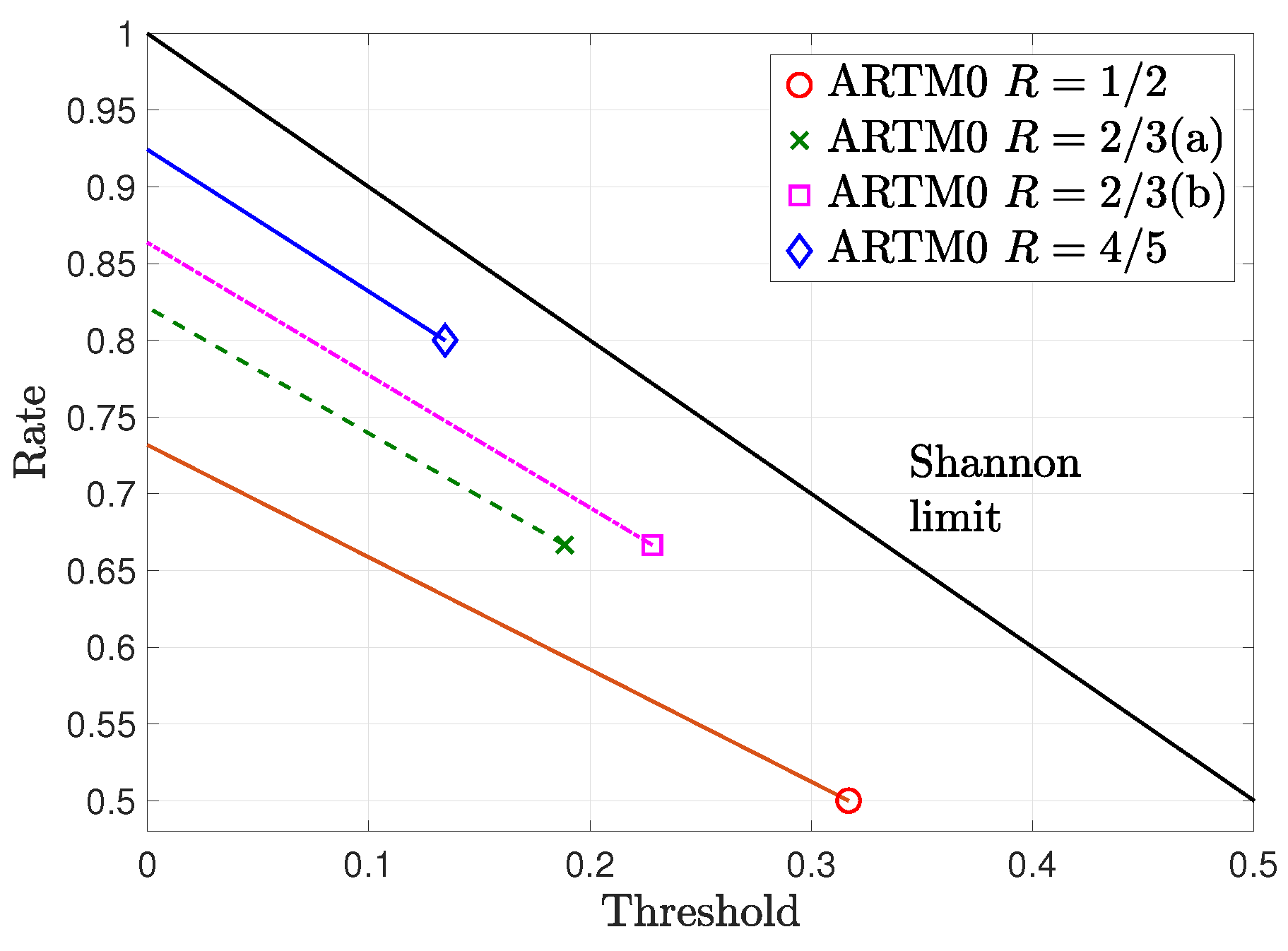
Figure 2.
Minimum distance growth rates for the punctured ARTM0 LDPC code ensembles.
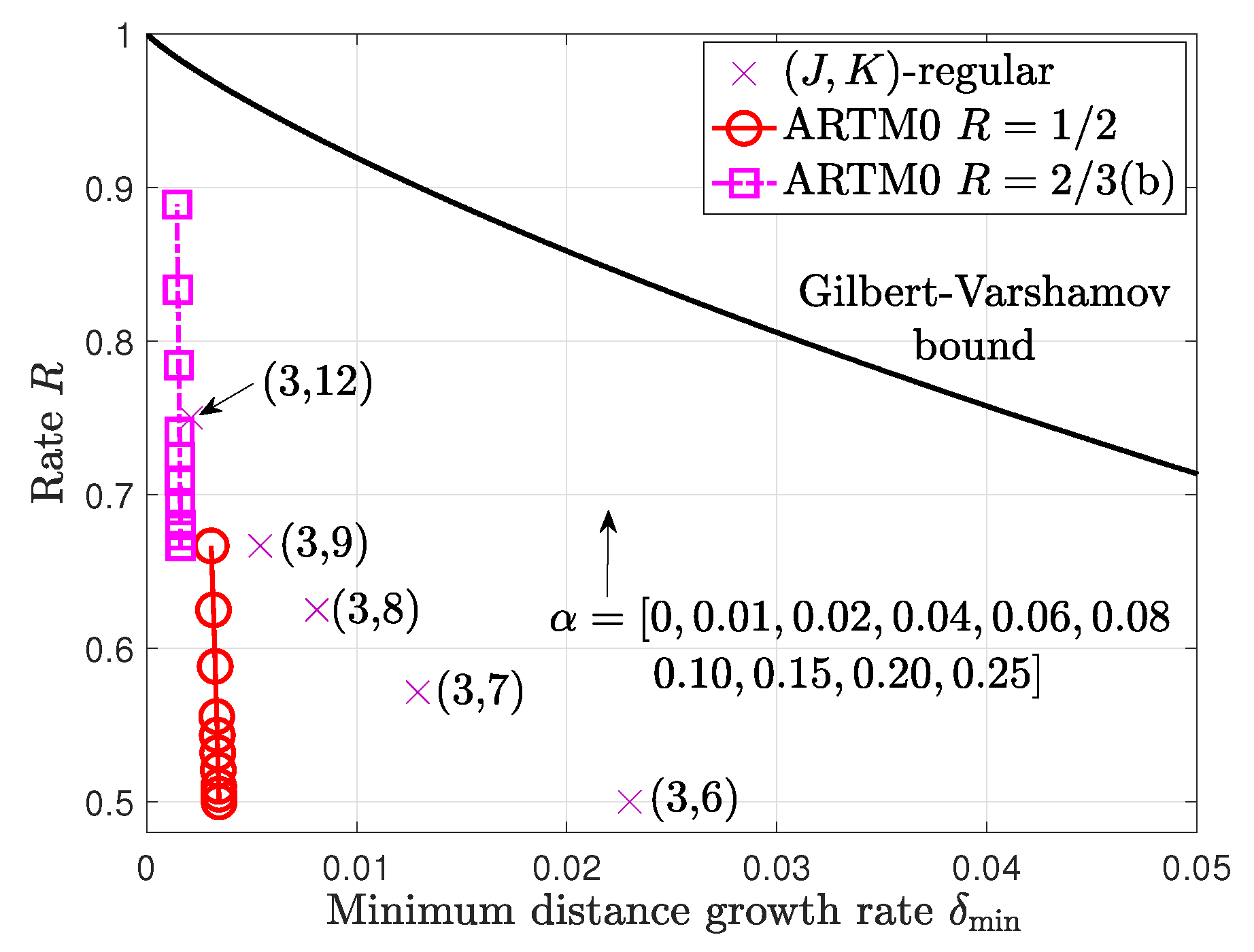
Figure 3.
Model transmitter for punctured LDPC code with CPM modulation.
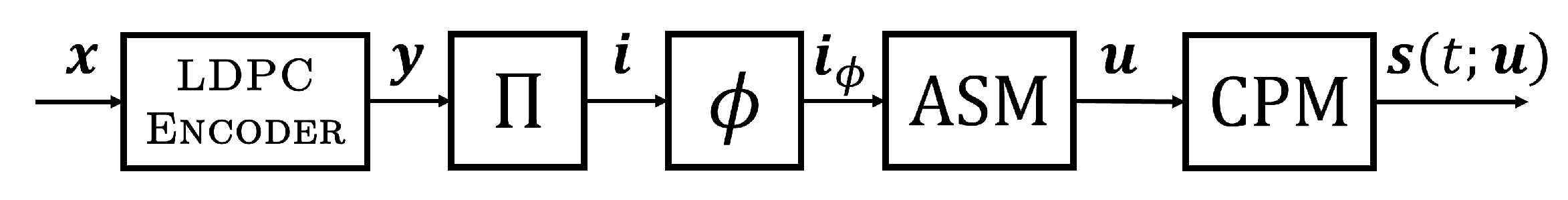
Figure 4.
Model receiver for punctured LDPC code with CPM modulation and iterative decoding.
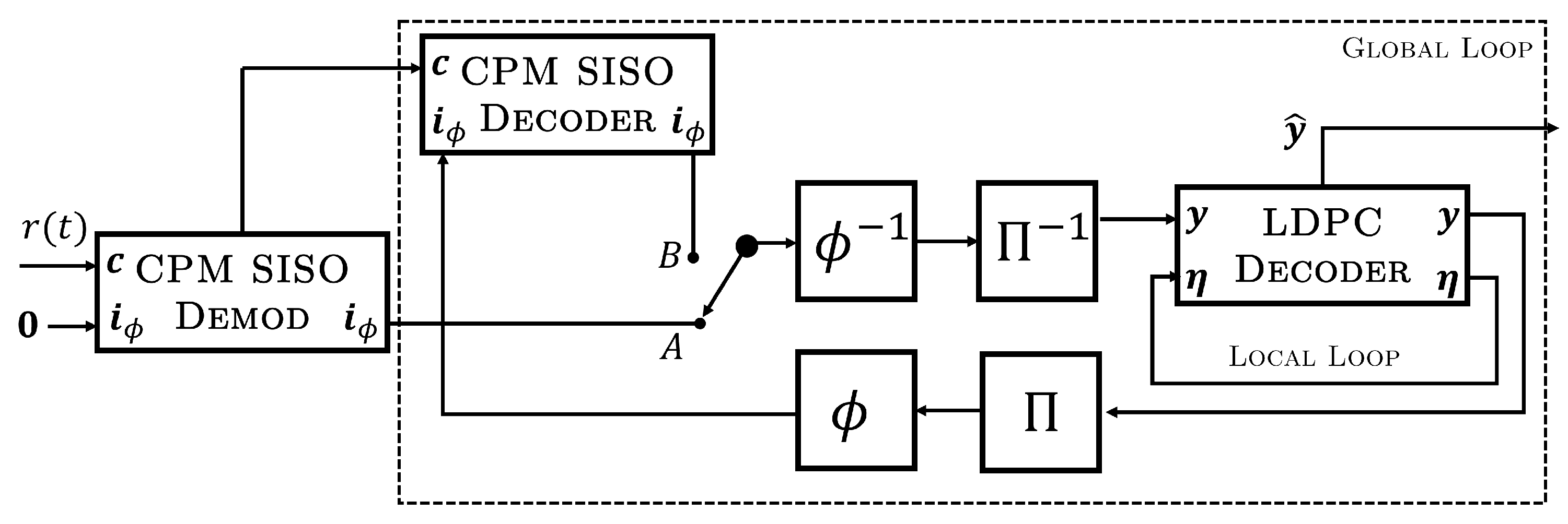
Figure 5.
Puncturing by truncation and depuncturing by zero-padding within the global decoding loop of the receiver.
Figure 5.
Puncturing by truncation and depuncturing by zero-padding within the global decoding loop of the receiver.
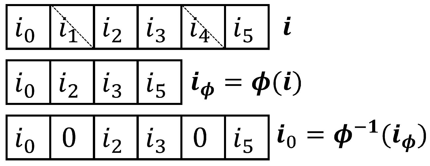
Figure 6.
Simplified transceiver model without CPM.
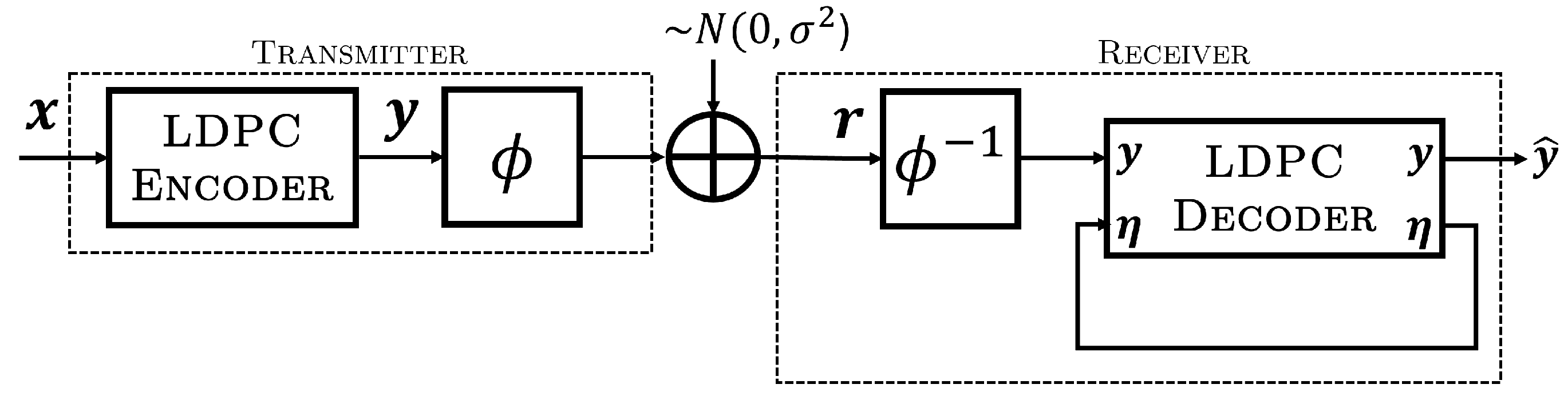
Figure 7.
BER performance without CPM for the , ARTM LDPC code with (dashed) and without (solid) random puncturing.
Figure 7.
BER performance without CPM for the , ARTM LDPC code with (dashed) and without (solid) random puncturing.
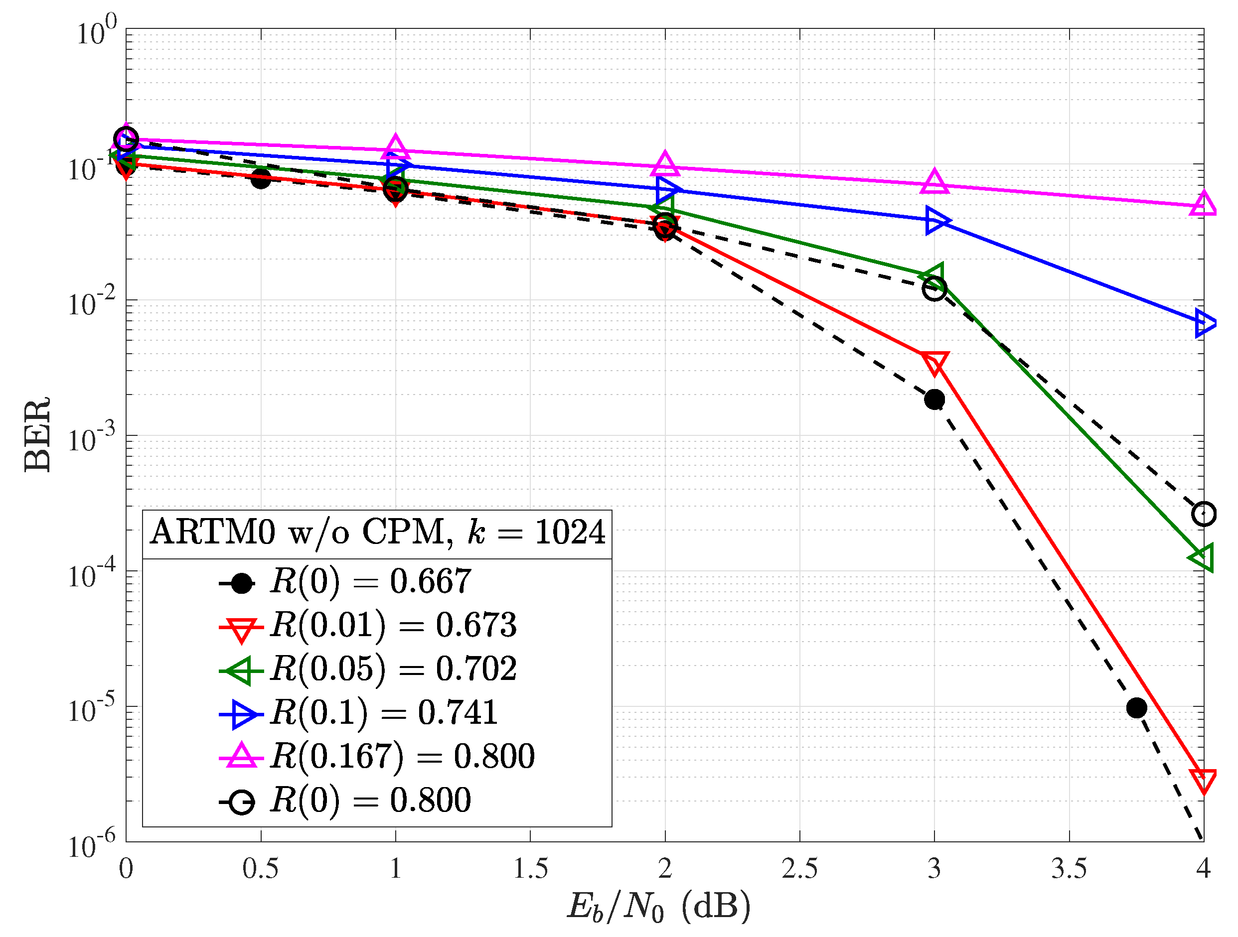
Figure 8.
BER performance with CPM for the , ARTM LDPC code with (dashed) and without (solid) random puncturing.
Figure 8.
BER performance with CPM for the , ARTM LDPC code with (dashed) and without (solid) random puncturing.

Figure 9.
BER performance in terms of with CPM for the , ARTM LDPC code with (dashed) and without (solid) random puncturing.
Figure 9.
BER performance in terms of with CPM for the , ARTM LDPC code with (dashed) and without (solid) random puncturing.
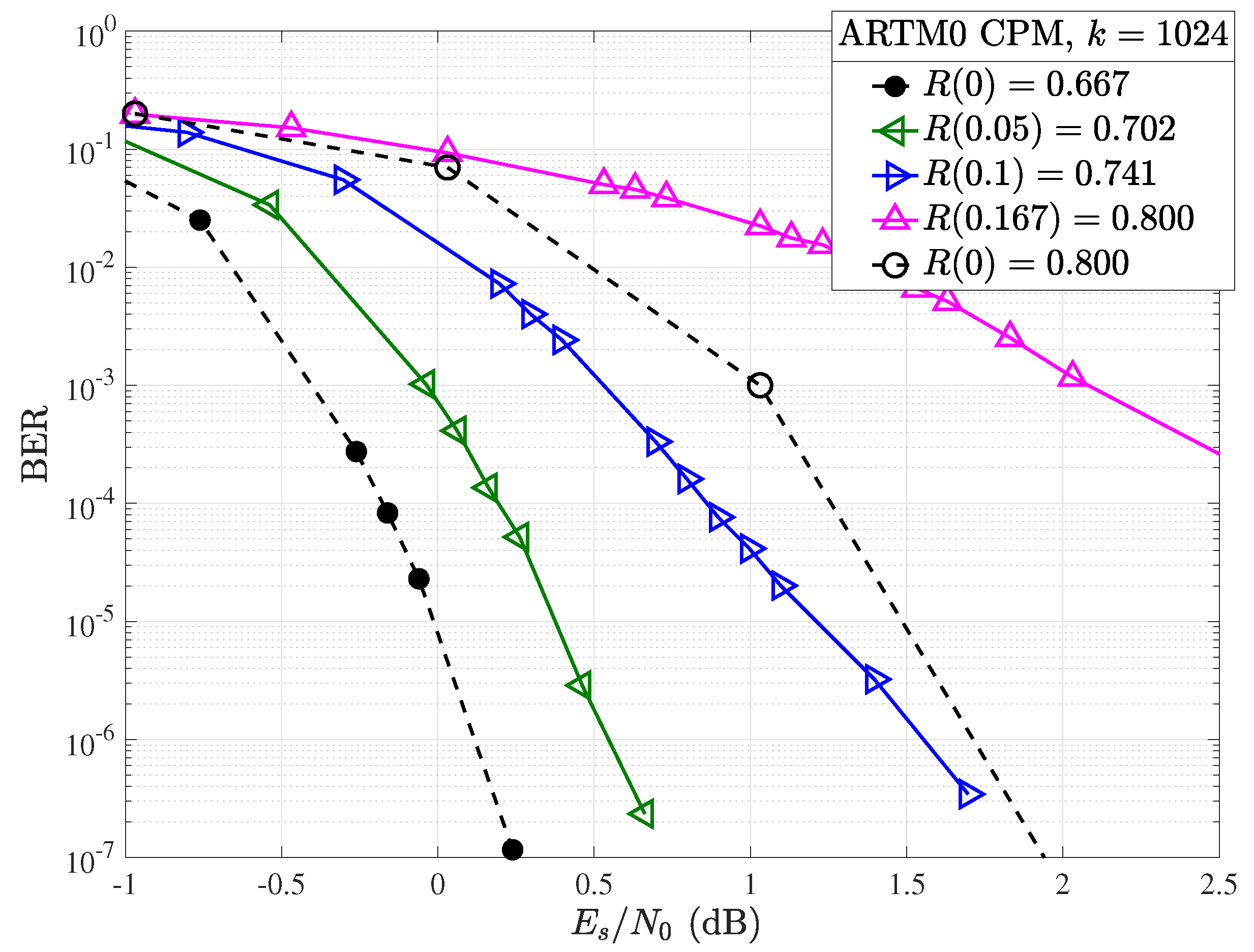
Figure 10.
Modification to transmitter circuit includes module S to shorten the information bit sequence.
Figure 10.
Modification to transmitter circuit includes module S to shorten the information bit sequence.
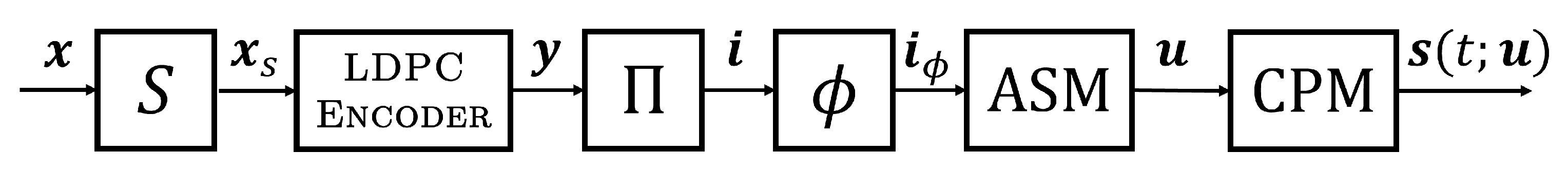
Figure 11.
Simplified input stage of the shortening decoder showing an example of the module producing infinite LLR outputs.
Figure 11.
Simplified input stage of the shortening decoder showing an example of the module producing infinite LLR outputs.
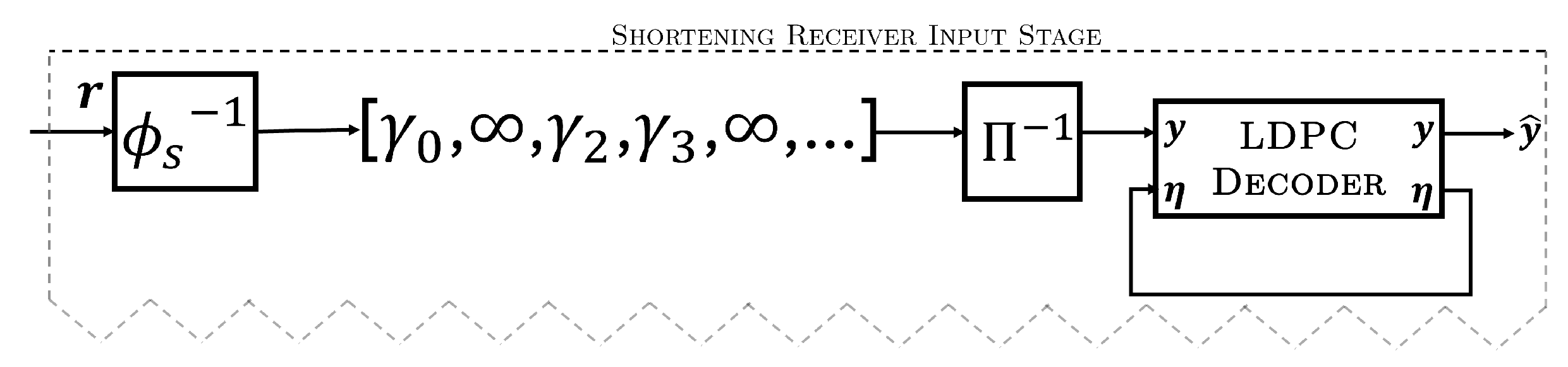
Figure 12.
Random shortening applied to the ARTM0 and codes in terms of symbol energy .
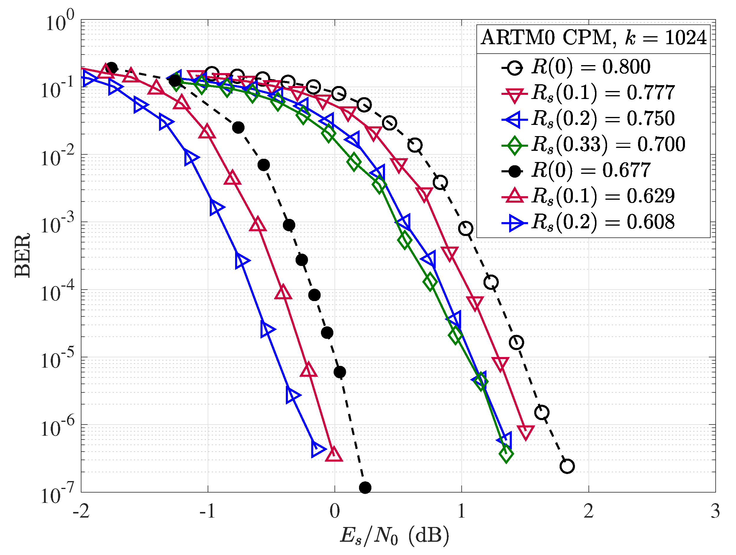
Figure 13.
Random shortening applied to the ARTM0 and codes in terms of information symbol energy .
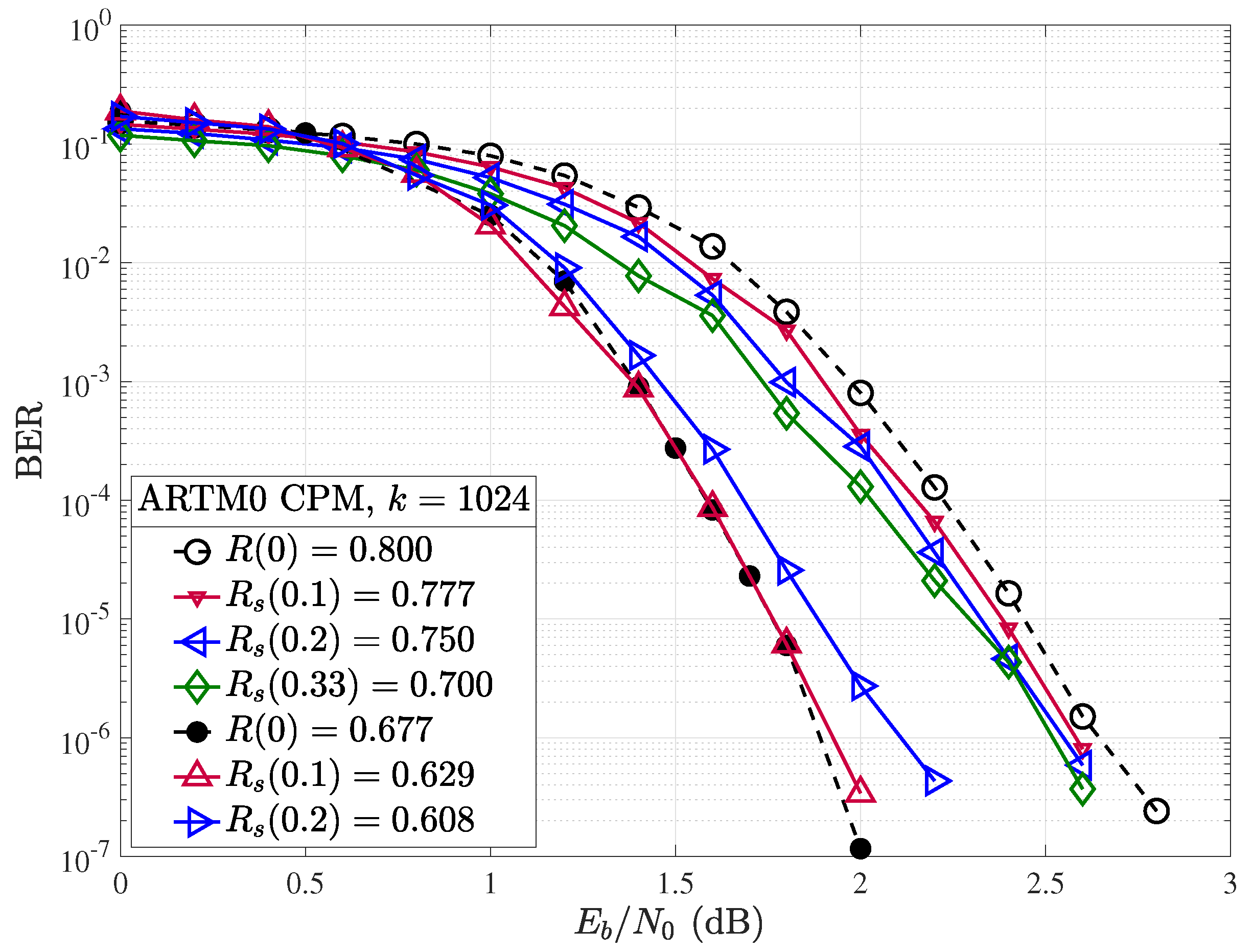
Figure 14.
Random shortening applied to the ARTM0 and codes with .
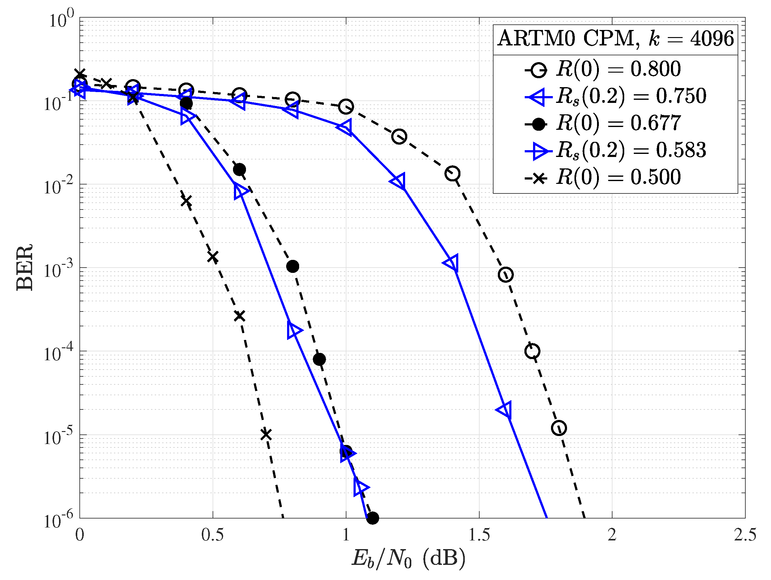
Figure 15.
BER performance for the , ARTM LDPC code with random puncturing (solid) alongside the , ARTM LDPC code with random shortening (dot-dash).
Figure 15.
BER performance for the , ARTM LDPC code with random puncturing (solid) alongside the , ARTM LDPC code with random shortening (dot-dash).
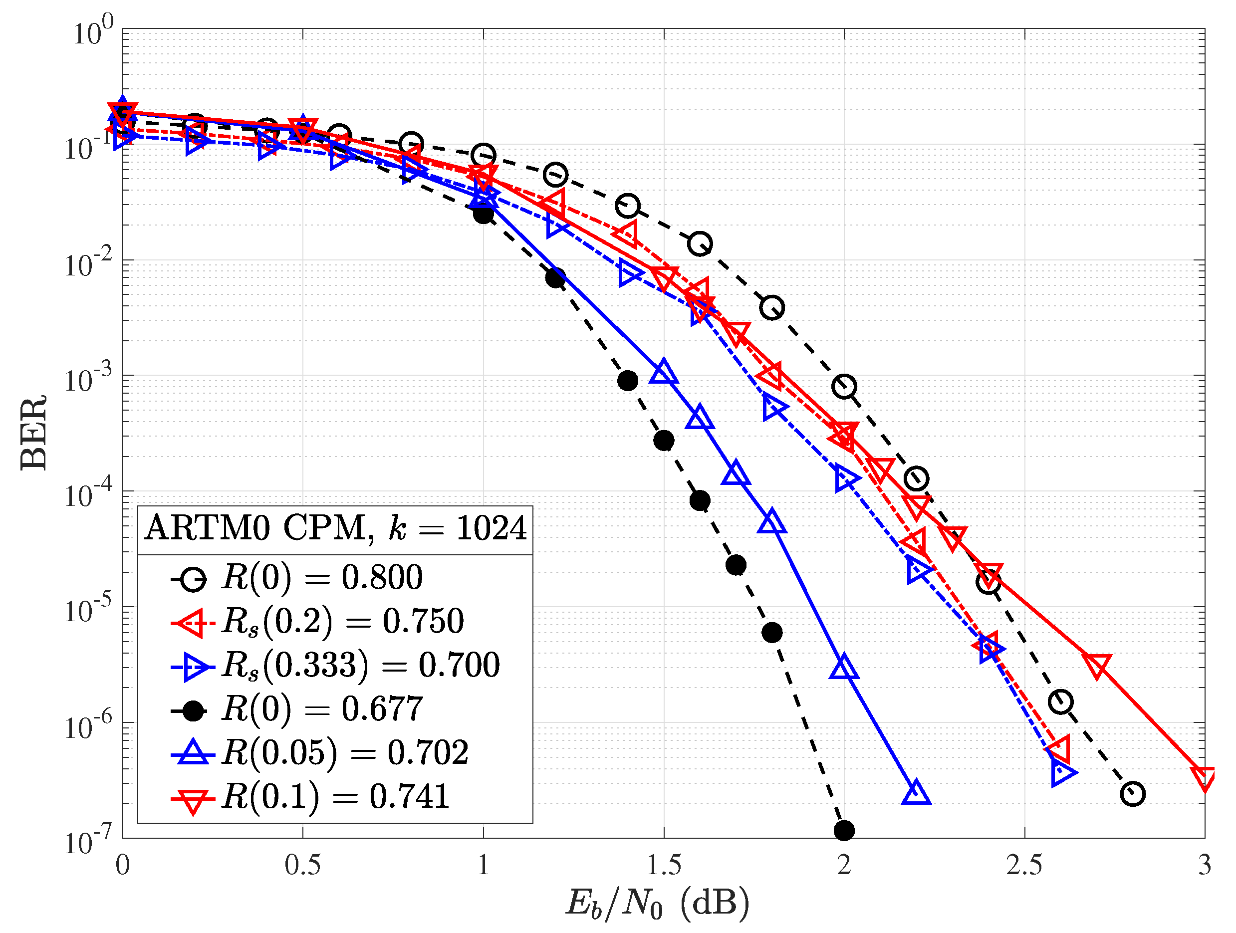

Table 1.
Minimum distance growth rates for the ARTM0 LDPC code ensembles.
| ARTM0 | ||||
|---|---|---|---|---|
Disclaimer/Publisher’s Note: The statements, opinions and data contained in all publications are solely those of the individual author(s) and contributor(s) and not of MDPI and/or the editor(s). MDPI and/or the editor(s) disclaim responsibility for any injury to people or property resulting from any ideas, methods, instructions or products referred to in the content. |
© 2024 by the authors. Licensee MDPI, Basel, Switzerland. This article is an open access article distributed under the terms and conditions of the Creative Commons Attribution (CC BY) license (http://creativecommons.org/licenses/by/4.0/).
Copyright: This open access article is published under a Creative Commons CC BY 4.0 license, which permit the free download, distribution, and reuse, provided that the author and preprint are cited in any reuse.


