Preprint
Article

Development and Engineering Application of the Mechanized Grooving Device for Slope Protection Grid Beams

Altmetrics

Downloads

64

Views

25

Comments

0

Submitted:

28 October 2024

Posted:

29 October 2024

You are already at the latest version

Alerts
Abstract
In slope engineering, the foundation grooves of slope protection gird beams are mostly excavated manually. However, manual excavation presents problems, such as low construction efficiency, uneven groove bottoms, inconsistent cross-section groove widths, and curved groove axis, which reduces the quality of cast-in-place grid beams or complicates the installation of prefabricated grid beams. To address these issues, a mechanized grooving device for slope protection grid beams has been developed and successfully applied in the project. The grooving device is composed of interlocking dual spiral cutter heads, a mechanism for the groove width and depth adjustment, a cutter head working platform, a platform azimuth adjuster, a cutter head sliding mechanism, a hydraulic motor, a hydraulic power system and a platform anchoring mechanism. It can be used to groove on soil and strongly weathered rock slopes at different slope angles, and the foundation grooves of slope protection gird beams of different depths and widths can be carved according to the design requirements. Moreover, the grooved trenches feature flat bottoms, consistent widths, and straight axis, making it easy to install prefabricated grid beams and greatly improving the quality of cast-in-place grid beams. According to the construction statistics of a slope project in Guangdong, the grooving speeds of the grooving device on the slope of soil and strongly weathered rock are about 1.5m/min and 0.5m/min respectively, which greatly improves the construction efficiency and quality.
Keywords: 
Subject: Engineering  -   Civil Engineering

0. Introduction

Slope protection engineering has long been a critical issue in infrastructure projects, such as transportation and water conservancy. Currently, the slope protection grid beam structure of the anchor rod and cable is widely used in slope protection engineering [1], which has quite mature construction technique, and relatively low project cost [2]. Nowadays, most foundation grooves of slope protection grid beams are excavated manually. However, this method presents problems, such as low construction efficiency, uneven groove bottoms, inconsistent cross-section groove widths, and curved trench axis, which lowers the quality of cast-in-place grid beams or complicates the installation of prefabricated grid beams. Additionally, the cast-in-place construction of grid beam not only consumes a significant amount of labor but also prolongs the construction period. After slope excavation and unloading, the long exposure of the slope surface increases the chances of rainwater infiltration and erosion, thus heightening the instability of the slope surface and slope body. Therefore, the prefabricated construction concept has been applied to slope protection engineering [3,4,5,6,7]. Compared to traditional cast-in-place structures, the prefabricated modular structure offers numerous advantages, including shorter construction period, higher production efficiency, less material consumption, superior finished product quality, and being more low-carbon and environmentally-friendly[8,9,10]. Furthermore, in slope projects, it is easier to repair and reinforce slopes in blocks, which is conducive to realizing the concept of simultaneous slope excavation and reinforcement. However, prefabricated components are often heavy, and the installation site is typically confined, meaning that the construction of prefabricated structures requires advanced equipment. Currently, the lack of mechanized construction equipment restricts the development and widespread application of prefabricated slope protection structures. Since the 1980s, China has gradually shifted from importing mechanized construction equipment to independently innovating and developing its own [11,12,13,14,15,16,17]. To overcome the challenges of manual excavation in grid beam foundation groove, this paper introduces a mechanized grooving device for slope protection grid beams, which has been successfully applied in engineering projects. This grooving device is composed of interlocking dual spiral cutter heads, a mechanism for the groove width and depth adjustment, a cutter head working platform, a platform azimuth adjuster, a cutter head sliding mechanism, a hydraulic motor, a hydraulic power system, and a platform anchoring mechanism. It can be used to groove on soil and strongly weathered rock slopes at different slope angles, and the foundation grooves of slope protection gird beams of different depths and widths can be carved according to the design requirements. Moreover, the grooved trenches feature flat bottoms, consistent widths, and straight axis, making it easy to install prefabricated grid beams and greatly improving the quality of cast-in-place grid beams.

1. Composition and Working Principle of the Grooving Device

1.1. Subsection

The grooving device consists of interlocking dual spiral cutter heads, a mechanism for the groove width and depth adjustment, a cutter head working platform, a platform azimuth adjuster, a cutter head sliding mechanism, a hydraulic motor, a hydraulic power system, and a platform anchoring mechanism. The components of the device are shown in Figure 1.

1.2. Overall Design of Slope Grooving System

In order to adapt to complex and variable topography, the slope grooving system should have flexible and mobile capabilities. Therefore, this paper develops a grooving system based on an existing long-arm excavator, which replaces the grab bucket of the excavator with a grooving platform, and utilizes the flexible maneuvering characteristics and hydraulic power system of the long-arm excavator to realize flexible, mobile positioning and grooving. The main structural components of the grooving platform include the positioning system, groove depth and width adjustment system, excavation cutter disk system, self-stabilization system, and control system.

1.3. Design of the Spatial Positioning System

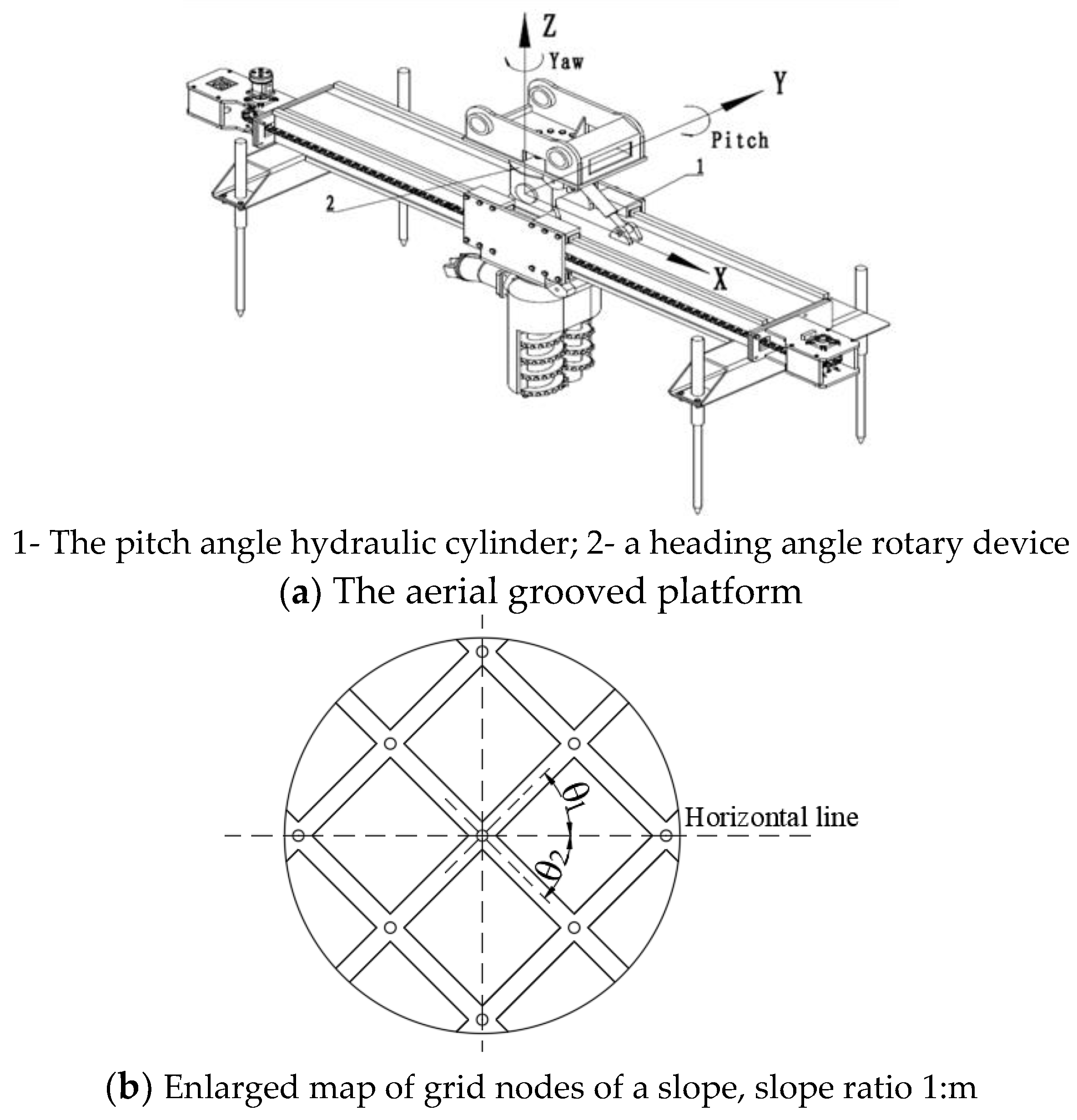
The spatial positioning system consists of the positioning system of the long-arm excavator, a pitch angle hydraulic cylinder on the grooving platform, a heading angle rotary device, and a 3D spatial attitude sensor. The MCU controls the pitch angle hydraulic cylinder and the heading angle rotary device to manipulate the attitude of the aerial grooved platform, as shown in Figure 2.
The process of positioning groove with the grooving machine is as follows: The first step is to adjust the center point of the grooving platform to the intersection point of the intended "cross-shaped" groove. Next, the slope ratio is input to the MCU, which calculates the pitch of the spatial platform according to the slope ratio. Then, the angles θ 1 and θ 2 between the two grooves of the spatial grooving platform and the horizontal line as shown in Figure 2b are taken as the two heading angles (yaw) of the platform. Finally, the MCU is manipulated, and the grooving spiral cutter is placed at the midpoint of the main beam of the air platform, following the previously determined pitch angle and heading angles to sequentially groove the two grooves shown in Figure 2b.

1.4. Groove Width and Depth Adjustment Mechanism

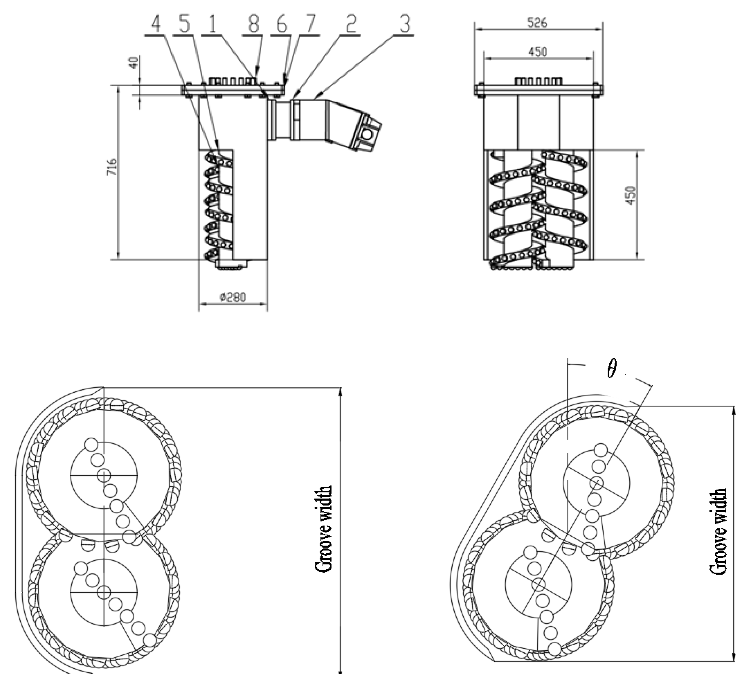
The groove width adjustment mechanism comprises a motor, a reducer connected to the motor, and a rotating bracket connected to the reducer. The rotating bracket is connected to the milling groove drilling bit and is powered by the motor. As shown in Figure 3, the rotation of the bracket controls the angle between the long axis direction of the pair of spiral cutters and the cross-section of the groove, thereby adjusting the milling groove width. When the angle is 0°, the maximum groove width can reach B ; when the angle is α , the groove width x = B c o s ,   and when the angle is 90°, the minimum groove width is 1 2 B . Therefore, the groove width can be selected between 1 2 B   and   B   to accommodate the installation requirements of slope protection grid beams with different cross-section sizes, allowing for arbitrary groove widths within a certain range. The groove depth is determined by the excavator operator drilling at the intersection point of the cross-shaped groove. A depth sensor is installed on the spatial platform, which can display real-time data on the control panel, allowing for the drilling to continue until the design groove depth is reached.

1.5. Excavation Cutter Disk System

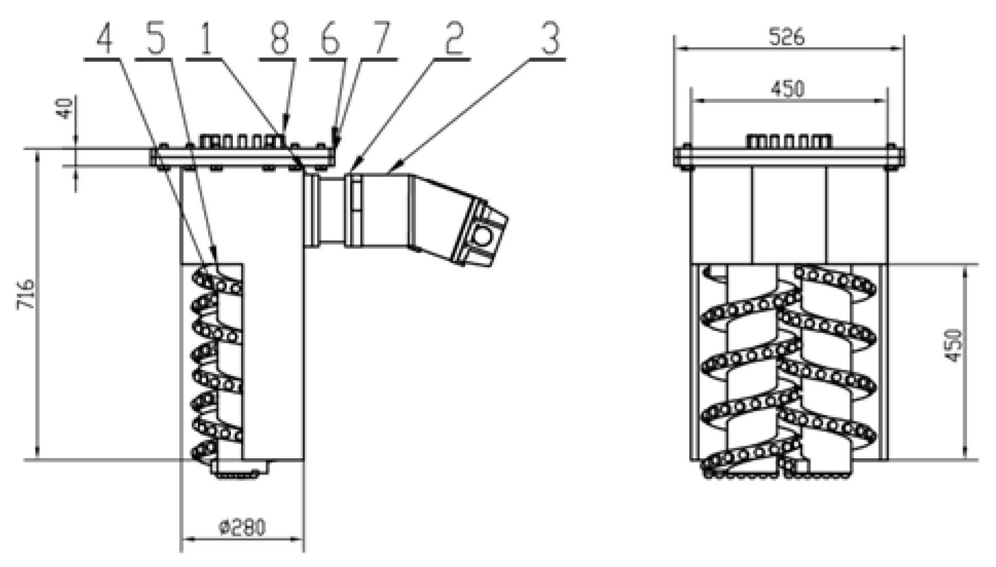
This grooving device introduces an interlocking dual spiral cutter head structure, as shown in Figure 4. The grooving depth of the cutter disk is not affected by the support frame of cutter disk, allowing for a smaller disk diameter. Additionally, the dual spiral structure generates relatively low counterforce and can automatically pull downward, effectively enhancing the stability of the grooving frame. At the same time, the dual spiral cutter disk not only improves excavation efficiency but also enhances the smoothness and flatness of the groove.

1.6. Self-Stabilization System and Control System

Once the grooving machine is positioned and begins grooving, it is crucial to ensure that the grooving system remains stable during the process of mechanical grooving so that it can groove along the set path and depth. This paper designs an automatic drilling system of fixed anchor claw in conjunction with a pressurization system integrated with the excavator arm. These systems ensure that the grooving frame stays stable and remains tightly affixed to the slope surface during grooving.
The control system primarily manages the operation of the grooving machine. It consists of a hydraulic control unit, with basic functions implemented through the hydraulic actuation system. These functions include operating the grooving machine's spatial positioning, controlling the three-axis directional angles, locking positions, and managing grooving actions and power control. The control system can be placed inside the excavator's operator cabin, allowing the operator to control the grooving equipment via buttons or joysticks, making the system simple and flexible to operate.

2. Main Parameters of the Grooving Technology and Device

2.1. Principle and Technology of the Grooving Machine

According to the slope grid design diagram, the grooving lines and nodes are marked on the brushed slope, and then the grooving operation begins.
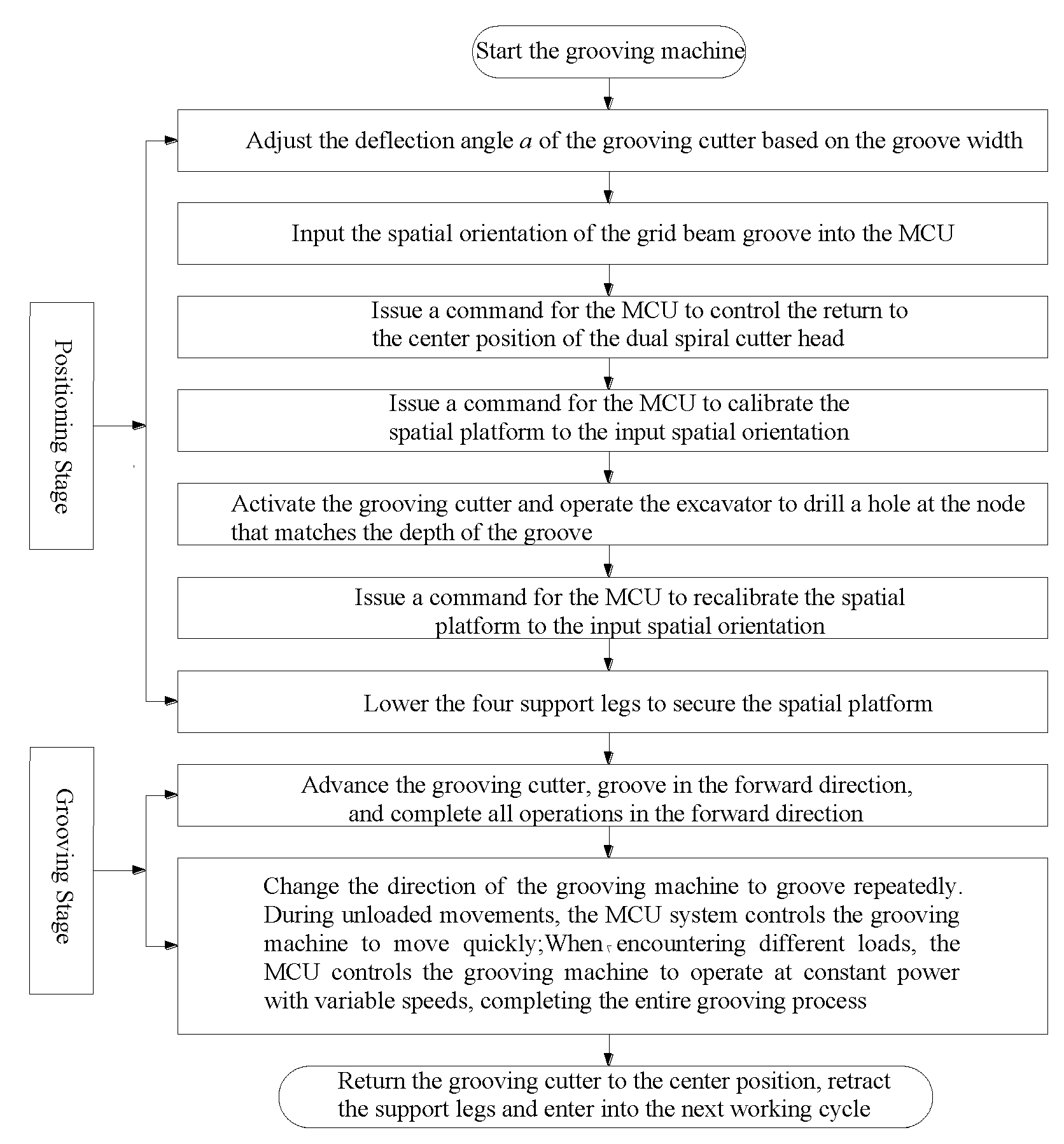
The grooving operation consists of two stages: the positioning stage and the grooving stage. Positioning Stage: First, the grooving machine is placed on the slope to be grooved using the hydraulic cylinder of the excavator's rotary platform. The direction of the pair of spirals on the milling groove drilling bit is rotated and adjusted according to the required groove width as specified in the design drawings. The grooving machine is then adjusted to the correct spatial orientation to match the grid beam groove, controlled by the MCU. The hydraulic cylinders of the excavator, as well as the swing cylinder, are used to control the tilt of the grooving machine along both the slope and vertical directions. By pressing down the excavator arm, the grooving machine's stability is maintained in the vertical direction to the slope. The four support legs are pressed down to fix the grooving machine in place, completing the positioning stage. Grooving Stage: The grooving cutters are activated, and the machine grooves in the forward direction. After completing one section of grooving, the worm gear rotary device and the sliding frame are adjusted to change the grooving machine's direction. The platform reciprocates grooving movement. During unloaded movements, the MCU system controls the rapid movement of the groove cutter to increase efficiency. When encountering different load conditions, the MCU system adjusts the grooving machine to operate at variable speeds with constant power, completing the entire "cross-shaped" groove. Afterward, the grooving cutter is returned to the center position, the support legs are retracted, and the two stages are repeated in the next section of the slope. The grooving process is shown in Figure 5.
The mechanized grooving device for slope grid beams is designed with a guide rail installed on the guide rail platform. The sliding block is connected to the guide rail in a sliding manner and is driven by a sprocket and chain mechanism to move left and right. The spiral system consists of a milling groove drilling bit, a groove depth feed mechanism, and a groove width adjustment mechanism. The milling groove drilling bit includes a pair of spirals rotating in opposite directions, left and right unearthed baffles, a hydraulic motor, and a gearbox. The spirals are rotated by a worm gear rotary device to carry out the grooving operation.
The milling groove drilling bit is mounted on the sliding block through the groove width adjustment mechanism and is driven by the hydraulic motor and the sprocket and chain to move left and right along the guide rail, completing the sectional grooving process. Position switches are installed at both ends of the guide rail platform to control the sectional range of the milling groove drilling bit's grooving and to prevent mechanical interference at the ends of the platform, ensuring the safety of the device. When the milling groove drilling bit slides to either end of the platform, the position switch controls the sliding block to move back and forth in the opposite direction. Simultaneously, the depth feed mechanism advances the milling groove drilling bit deeper into the groove, milling layer by layer until the predetermined groove depth is reached, completing the grooving process for that section.
The groove depth feed mechanism includes a hydraulic motor, a screw rod for the spiral feed drive, and a sliding block for the spiral feed. The hydraulic motor is connected to the screw rod for the spiral feed drive, and the screw rod is connected to the sliding block, which facilitates the up-and-down movement of the sliding block. The worm gear rotary device is connected to the dual-axis spiral, driving the dual-axis spiral to rotate. The sliding block for the spiral feed is connected to the worm gear rotary device, enabling the up-and-down feeding of the dual-axis spiral. The spiral system is equipped with a spiral feed depth sensor to detect the feed depth, allowing for arbitrary groove depths within a specified range. The sliding pair can be either a cylindrical sliding pair or a planar sliding pair. The spiral feeder is driven by the hydraulic motor, allowing for forward and reverse rotation, which causes the milling groove drill to slide up and down to achieve the layered grooving process. The spiral blades of the cutter are embedded with high-strength alloy teeth. The spiral feeder, again driven by the hydraulic motor, rotates in both directions to facilitate the vertical sliding of the milling groove drilling bit and achieve the layered grooving process.
The groove width adjustment mechanism consists of a motor, a reducer connected to the motor, and a rotating bracket connected to the reducer. The rotating bracket is connected to the milling groove drilling bit. The motor can drive the rotation of the rotating bracket, which controls the arrangement direction of the pair of spirals on the milling groove drill to adjust the groove width, so as to accommodate the installation requirements of grid beams with different cross-sections, and allow for arbitrary groove widths within a specified range.
This grooving device is mounted on a power connection device that enables spatial positioning with multiple degrees of freedom, allowing for arbitrary adjustments of the grooving device's position and orientation before starting the grooving operation. The excavator provides the power to groove on the slope. The groove depth and width are controlled by the groove depth feed mechanism and the groove width adjustment mechanism, respectively, allowing for the creation of grid grooves with different cross-sectional dimensions on the slope to meet the installation requirements of slope grid beams with varying sizes. Segmented grooving is achieved by gradually moving the guide rail platform, with each segment of the groove connecting to form a grid groove for installing the slope grid beams. The prefabricated grid beams are then placed into the grooved slots for connection.
A physical representation of this grooving device is shown in Figure 6.

2.2. Main Parameters of the Device

The main parameters of the device are shown in Table 1.

3. Technology of Construction Operation
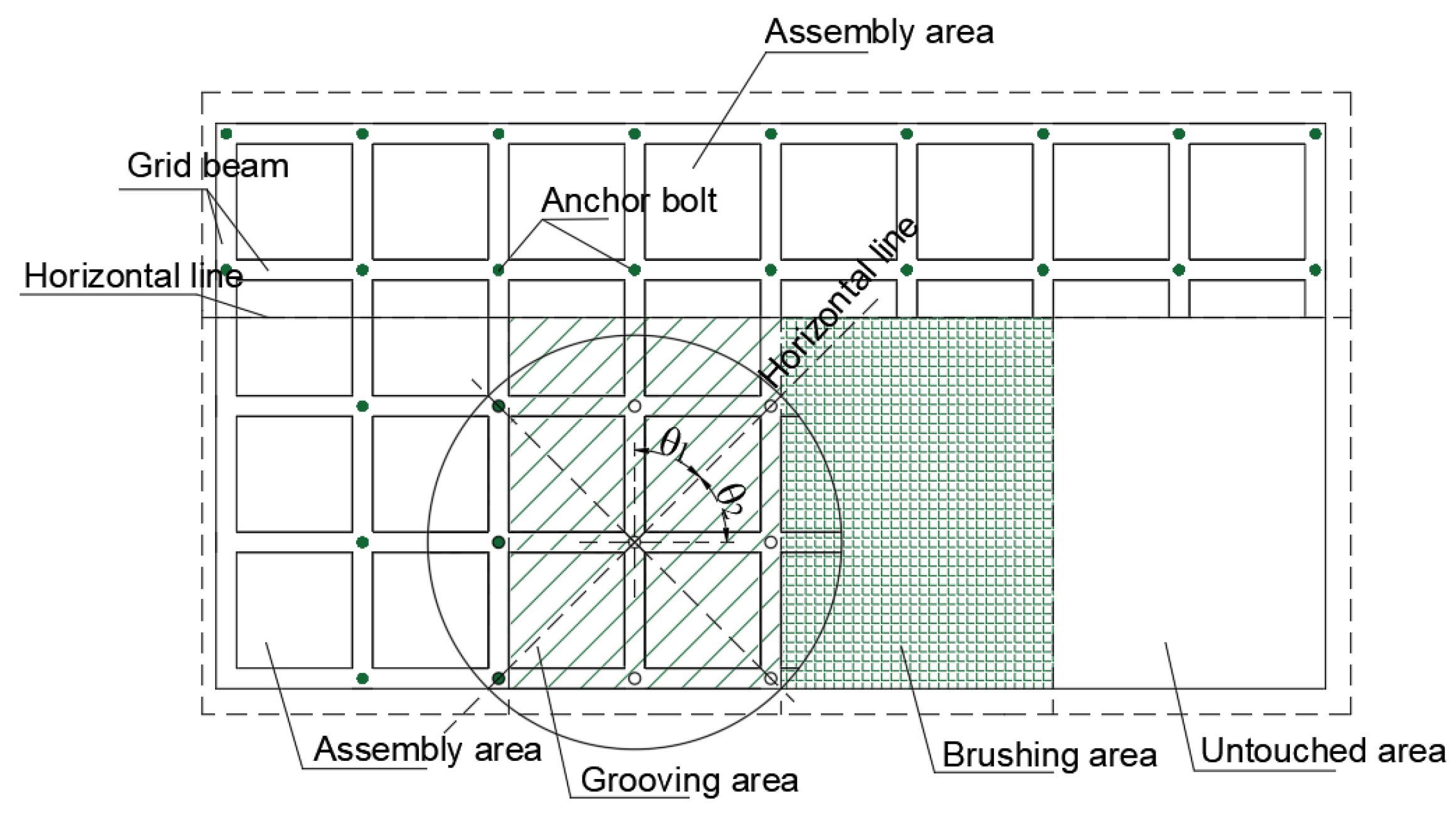
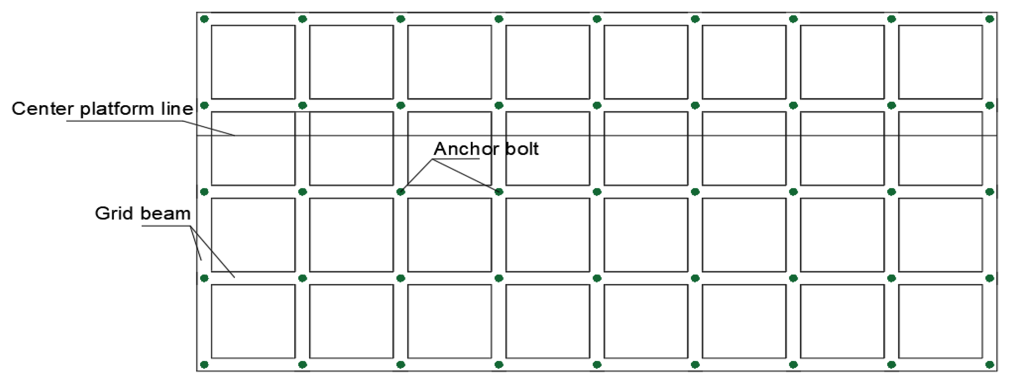
Figure 7 shows the slope elevation diagram after the grooving is completed and the anchor beam is installed in the existing slope construction. In the cast-in-place construction process, the slope is first brushed in stages. Once a certain level of the slope is fully brushed, the grooves are manually carved at the designated positions, anchor rods are installed, reinforcement cages are placed in the groove, and concrete is poured to ultimately complete the support operation for that level of the slope. This process has a longer construction period, and after the slope is brushed, it remains exposed for a long time, which can lead to instability during rainy conditions. Therefore, regulations require that we achieve simultaneous excavation and support.
By using the mechanized grooving method and prefabricated slope protection grid beams, the concept of simultaneous excavation and protection can be achieved. The construction process for simultaneous excavation and support is shown in Figure 7. The grooves of slope protection grid beam can be composed of "cross-shaped" grooves. The center point of the grooving machine, which is the intersection of the "cross-shaped" grooves, is used for positioning. After each positioning is completed, a groove is carved horizontally according to the design requirements. The grooving platform is then rotated 90° while keeping the center point stationary to carve a groove in the vertical direction, forming a "cross-shaped" groove. Subsequently, the grooving system is moved horizontally or vertically to carve out additional "cross-shaped" grooves that connect to the already carved grooves. This process is repeated, resulting in a grid pattern of grooves as shown in Figure 7. Finally, the entire grooving operation for the slope is completed, creating an interlaced grid of beams and grooves.
On a certain level of the slope, it can be divided into four areas: the first is the assembly area, where slope brushing and grooving have been completed, and grid beam installation is underway; the second is the grooving area, where slope brushing has been completed and the grooving device is currently working on the foundation groove; the third is the brushing area, where slope brushing operations are in progress; and the fourth is the untouched area, which retains the original appearance of the slope. This clearly illustrates that the combination of mechanized grooving and prefabricated slope protection structures can achieve the construction concept of simultaneous excavation and support.
Figure 8. Schematic diagram of the construction process.
Preprints 137711 g008

4. Application Examples

4.1. Field Test

The slope grid beam grooving device was tested on-site from May to August 2022 at a slope engineering site in Guangdong Province. The testing included assessing the grooving speed, foundation groove flatness, and other parameters.
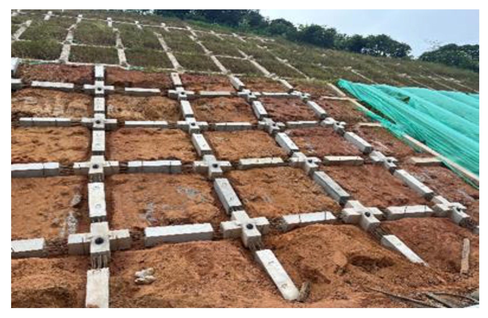
Before excavation, the machine was thoroughly calibrated to ensure that the entire construction process could proceed smoothly. To ensure that the excavation of the grid beam foundation groove met the design requirements for the slope, a zoned and layered approach was adopted. Prior to excavation, measuring and layout techniques were used to determine the scope of the foundation groove excavation. The slope construction utilized a stepped excavation method, with timely measurements taken after excavation to monitor conditions. Regular measurements of the foundation groove's depth, width, and slope were conducted, and close attention was paid to any signs of sliding or collapse within the groove. Appropriate measures were promptly taken if any issues were detected. The excavation process is illustrated in Figure 9a,b. The on-site assembly diagram is shown in Figure 10.

4.2. Test Results and Analysis

The testing process was conducted in accordance with relevant national standards. From the on-site operations, it can be observed that the grooving device operates smoothly and effectively achieves the set objectives. The operating speed is moderate. When grooving ordinary slopes, the speed can reach 1.5 m/min, while for weathered rock slopes, the speed can reach 0.5 m/min, indicating high working efficiency. Additionally, the excavated foundation grooves are flat and smooth, meeting the design requirements.

5. Conclusions

In response to the issues of low construction efficiency, uneven groove bottoms, varying cross-sectional widths, and curved groove axis associated with manual excavation methods in existing slope engineering, this paper has developed a mechanized grooving device for slope protection grid beams, which has been successfully applied in engineering projects. The main conclusions drawn are:
(1)
This paper presents a new technical approach that shifts the grooving of slope grid beams from manual construction to mechanized construction. The mechanized grooving device consists of interlocking double spiral cutting heads, groove width and depth adjustment mechanisms, a cutter working platform, a platform azimuth adjuster, a cutter sliding mechanism, a hydraulic motor, a hydraulic power system, and a platform anchoring mechanism. This device can perform grooving operations on slopes with different angles and varying degrees of weathered rock, accurately carving foundation grooves for slope protection grid beams to specified depths and widths, ensuring flat groove bottoms, consistent groove widths, straight axis, and facilitating the installation of prefabricated grid beams or significantly improving the quality of cast-in-place grid beams.
(2)
The mechanized grooving device developed in this paper achieves an excavation speed of approximately 9.6 m³/h per unit, which is significantly higher than the traditional manual excavation speed of 2 m³/d per person. This advancement can greatly save labor and accelerate construction speed.
(3)
Field tests have shown that the grooving speed of this device on soil and weathered rock slopes is approximately 1.5 m/min and 0.5 m/min, respectively. Compared to traditional manual construction methods, this significantly improves construction efficiency and quality, with satisfactory results that have important guiding significance for practical engineering.

References

  1. HanDongdong, Men Yuming, WangPeng. Model test on the influence of stiffness and spacing of lattice beam on the force of bolt lattice beam [J].
  2. Han Dongdong, Men Yuming, Hu Zhaojiang. Experimental study on anti-slip mechanism and force of lattice bolt of soil landslide[J]. Rock and Soil Mechanics, 2020,41(04):1189-1194+1202.
  3. Tu Ming. Development of automatic grooving machine for wooden sleepers for railway bridges[J]. Shanghai Railway Science and Technology, 2018(04):46-48.
  4. Liu Taiping. Research on the application of prestressed anchor cable technology in high slope protection[J]. China Residential Facilities, 2018(03):108-109.
  5. Li Rong, Huang Chunliang. Application of bolt lattice beam in high slope support engineering[J].Highway & Automobile Transport, 2017(03):102-104+161.
  6. Hou Xiaoqiang, Tian Shutao, Yao Zhengxue. Study on reinforcement mechanism and optimization design of high slope of frame prestressed bolt[J].Highway Engineering, 2015, 40(04):81-84+121.
  7. Han Dongdong, Men Yuming, Hu Zhaojiang. Experimental study on model of lattice prestressed bolt for landslide prevention and control[J]. Chinese Journal of Geotechnical Engineering, 2015, 37(08):1375-1380.
  8. Wang Juanjuan, Deng Juntao, Men Yuming. Model test of bolt lattice beam and calculation of internal force of lattice beam[J]. Hydrogeology & Engineering Geology, 2015, 42(02):64-68+76.
  9. Hao Jianbin, Li Jinhe, Cheng Tao, Men Yuming,Wang Banqiao. Study on vibration table model study of bolt lattice support slope[J]. Chinese Journal of Rock Mechanics and Engineering, 2015, 34(02):293-304.
  10. Zheng Ye, Fan Xiufeng, Shen Mengxing. Application of prestressed bolt lattice beam in the reinforcement of a highway slope[J]. Geotechnical Foundation,2014,28(01):1-1.
  11. Xiang Zuquan, Li Wanbai. Analysis and discussion on protection and reinforcement treatment technology of highway rock slope[J]. Urban Road, Bridge and Flood Control, 2012(05):50-52+57+7.
  12. Chen Daoyuan. Application of bolting lattice beam in soil slope support engineering[J]. Sichuan Building Materials, 2008(03):224-225+228.
  13. Lai Caidong. Application of bolting lattice technology in landslide prevention and control engineering[J]. Highway, 2008(03):37-38.
  14. CECS 22-2005, Technical regulations for geotechnical bolts (cables)[S].
  15. GB 50330-2002, Technical code for construction slope engineering[S].
  16. Li Jiaxin, Fang Hao, Cheng Yongliang, Lei Baodong, Guo Hong, Zheng Nan. Review of reinforcement mechanism and method of sandstone and soil[J]. Sichuan Architecture,2022,42(02):194-200.
  17. Cao Yican, Chen Peichong, Xu Guangbo. Research on slope protection structure design technology of prefabricated anchor sorghum beam[J]. China Survey & Design, 2020(05):94-97.
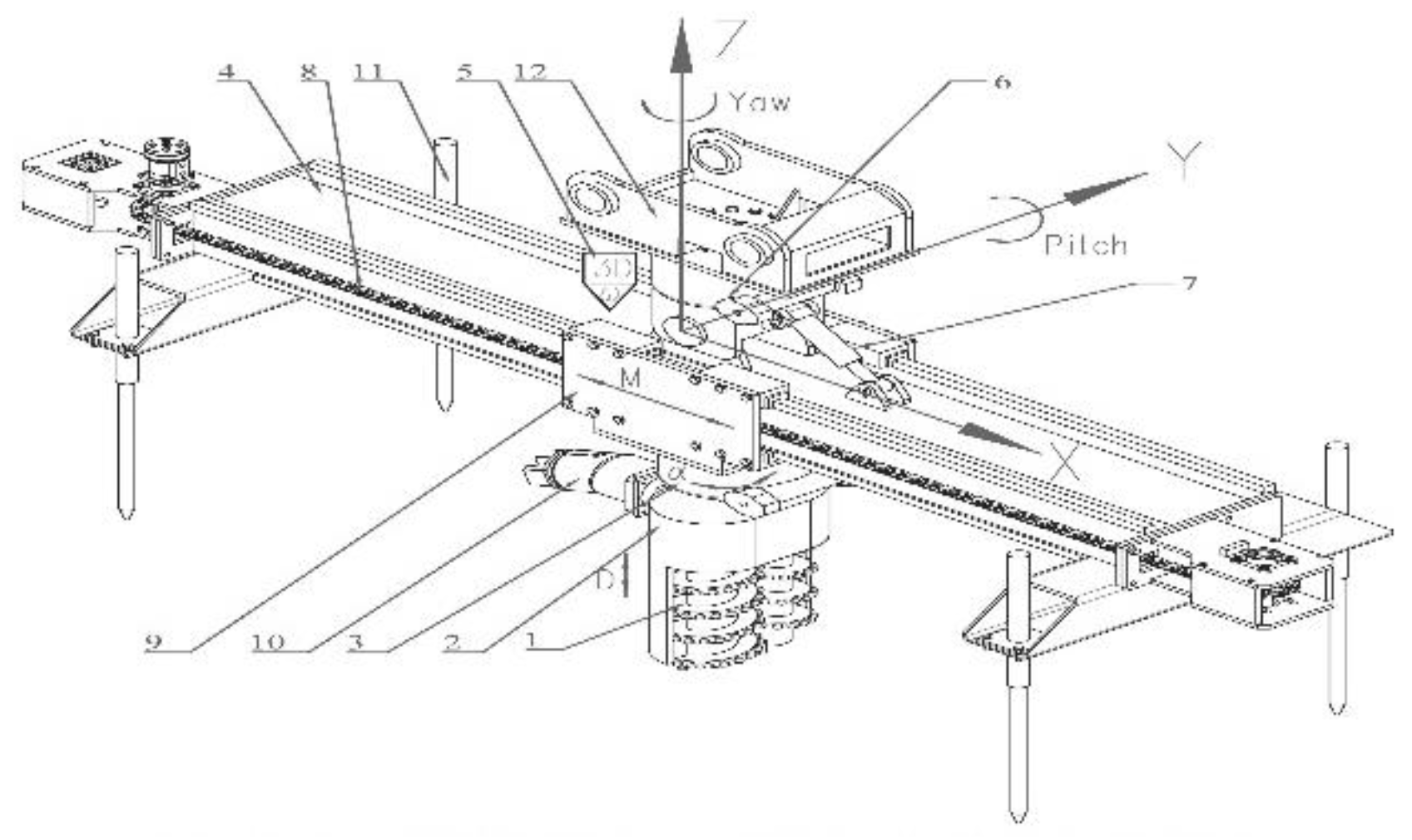
Figure 1. Device composition.Where, 1 represents the dual spiral cutter heads; 2 and 3 make up the mechanism for the groove width and depth adjustment; 4 is the cutter head working platform; 5, 6, and 7 form the platform azimuth adjuster; 8 and 9 constitute the cutter head sliding mechanism; 10 is the hydraulic motor; 11 is the platform anchoring mechanism; and 12 is the excavator arm connector. The hydraulic power system can be provided by an independent hydraulic system, such as that of an excavator.
Preprints 137711 g001
Figure 2. Schematic diagram of attitude control of aerial grooved platform.
Preprints 137711 g002
Figure 3. Schematic diagram of groove width adjustment.
Preprints 137711 g003
Figure 4. Dual spiral cutter head. 1. Milling cutter base 2. Reducer 3. Fixed displacement pump A2F 4. Left spiral cutter 5. Right spiral cutter 6. WEA9 support 1. 7.WEA9 support 2 8. Hex head full thread bolt (Class C 0).
Preprints 137711 g004
Figure 5. Flow chart of slope grooving.
Preprints 137711 g005
Figure 6. Actual diagram of the device. 1. Heading angle (yaw) rotary device of the aerial platform; 2. Pitch angle (pitch) driving cylinder of the aerial platform; 3. Main beam of the aerial platform; 4. Support leg hydraulic cylinder; 5. Grooving spiral cutter; 6. Spiral cutter rotary device; 7. Spiral cutter sliding pair; 8. Grooving power drive sprocket and chain; 9. Spatial 3D sensor and MCU controller.
Preprints 137711 g006
Figure 7. Elevation view of slope grid beams.
Preprints 137711 g007
Figure 9. Schematic diagram of the field work of the grooving machine
Preprints 137711 g009
Figure 10. On-site assembly diagram of prefabricated longitudinal and transverse beams with cross nodes.
Preprints 137711 g010
Table 1. Main parameters of the design.
Parameters Values
Overall dimension 3764mm×1150mm×2052mm
Power 50kW
Milling Width 27-40cm
Milling Depth 0-40cm
Single-Pass Grooving Length 0-2m
Disclaimer/Publisher’s Note: The statements, opinions and data contained in all publications are solely those of the individual author(s) and contributor(s) and not of MDPI and/or the editor(s). MDPI and/or the editor(s) disclaim responsibility for any injury to people or property resulting from any ideas, methods, instructions or products referred to in the content.
Copyright: This open access article is published under a Creative Commons CC BY 4.0 license, which permit the free download, distribution, and reuse, provided that the author and preprint are cited in any reuse.
Prerpints.org logo

Preprints.org is a free preprint server supported by MDPI in Basel, Switzerland.

Subscribe

© 2024 MDPI (Basel, Switzerland) unless otherwise stated