1. Introduction
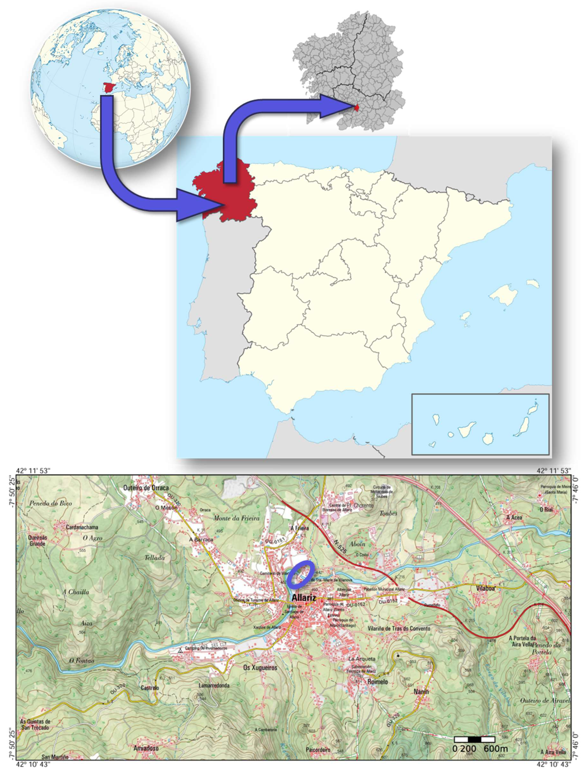
The Ponte de Vilanova (Vilanova Bridge) is located at the coordinates:
42º 11' 33.0" N.
7º 48' 10.0" W.
It is located in the town of Allariz, in the province of Orense, in Galicia, in the northwest of the Iberian Peninsula. (
Figure 1). Allariz is a town with an intense past and great economic and strategic importance [
1].
The Vilanova Bridge is a medieval bridge, built between the 13th and 14th centuries [
2,
3], which spans the Arnoia River, a tributary of the Miño River. It is possible that this bridge replaced another pre-existing bridge, built by the Romans in ancient times [
4,
5].
Several testimonies confirm that, throughout the 16th and 18th centuries, the Bridge suffered various damages and had to undergo various repairs [
1,
3] until it had the appearance it has today (
Figure 2 and
Figure 3).
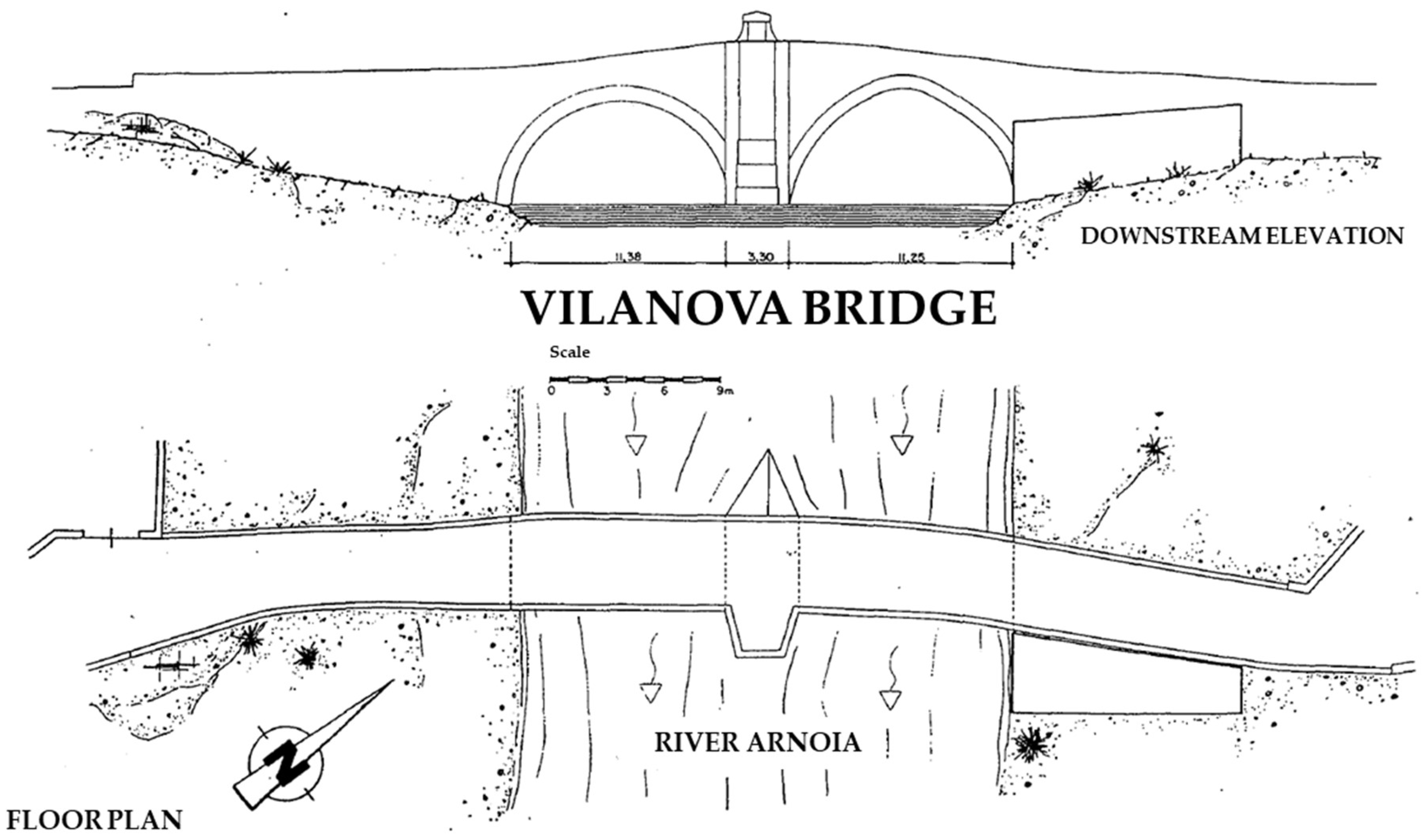
The bridge has two arches very close to the semicircular point. The spans of these arches are almost equal: 11.25 m and 11.38 m (
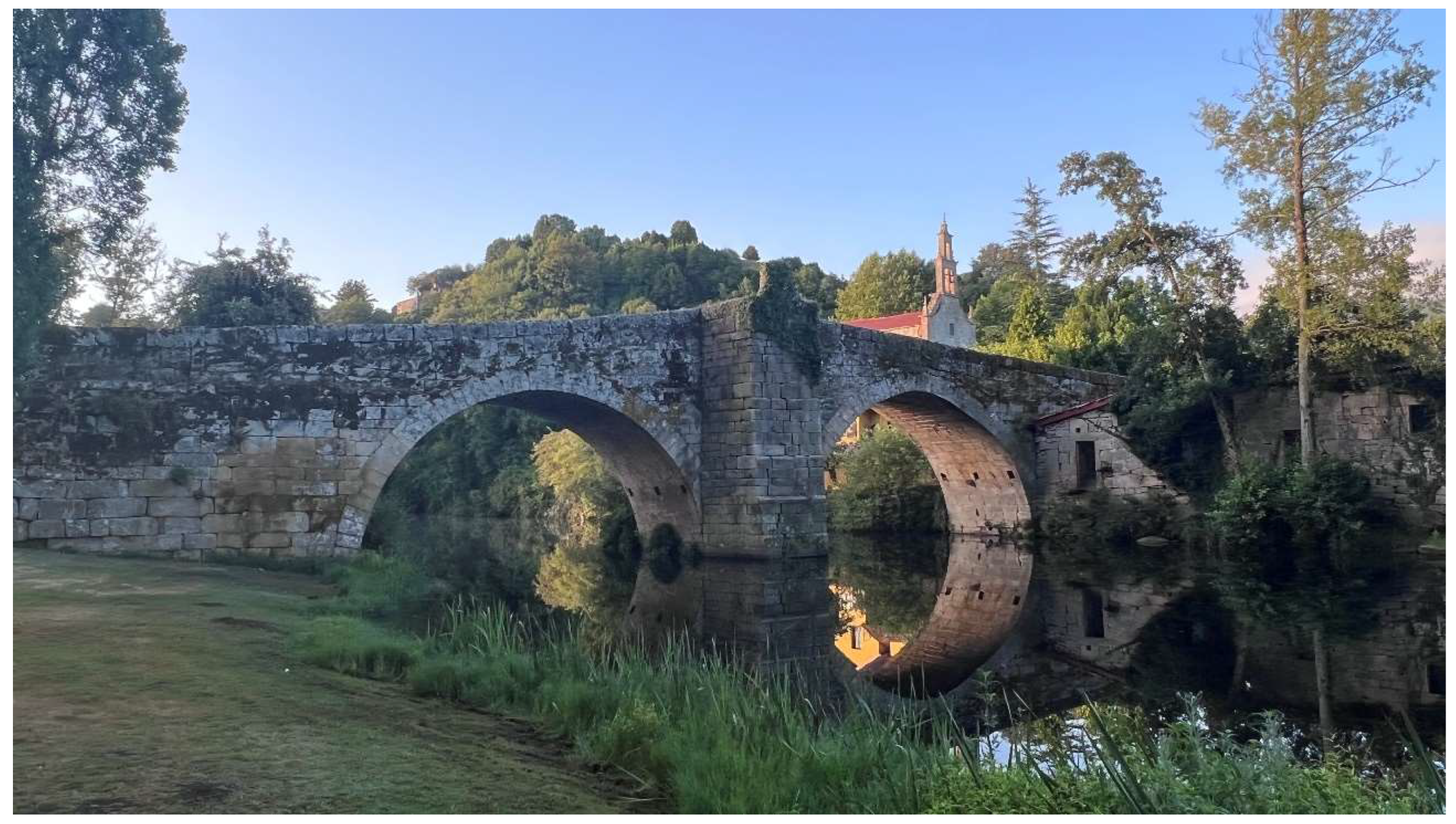
Figure 4). The intermediate pier, the only pier the bridge has, has a pointed starling and a cutwater. The starling is on the downstream side and does not reach the level of the roadway (
Figure 2). This starling is topped with a short pyramidal cap. Curiously, the cutwater does reach the level of the road (
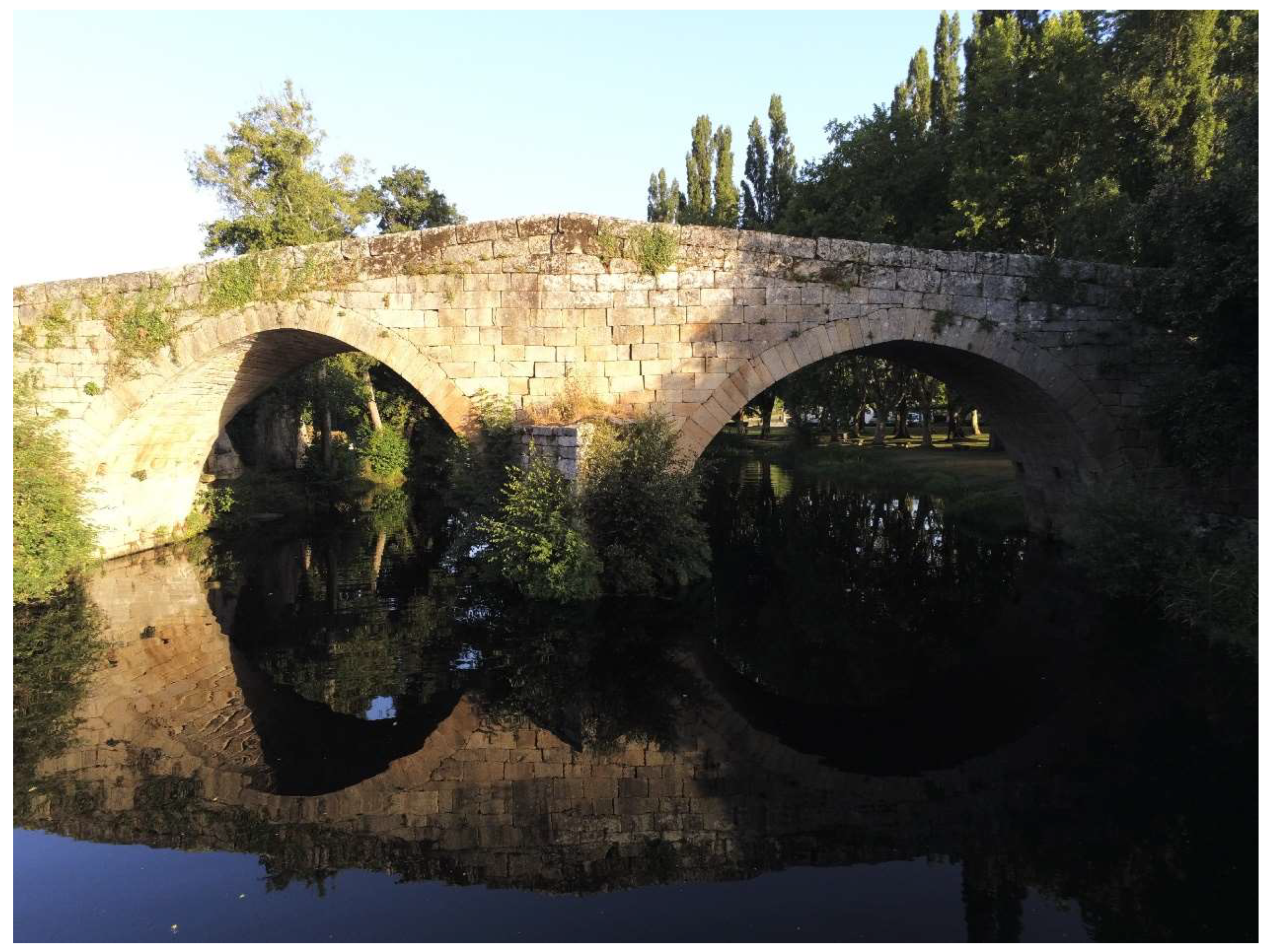
Figure 3), forming a siding. This siding over the breakwater has a trapezoidal shape when viewed in plan (
Figure 4) and shows a pediment with an inscription and the coat of arms of Allariz [
1,
2]. The starling and the cutwater are not locked: they are attached to the bridge. This indicates that they were probably built during one of the repairs carried out on the bridge [
1,
3].
Various stonemason marks can be seen on the vaults, all alphabetical [
1]. This detail confirms the medieval origin of the bridge [
4,
5].
The same goes for the profile of the bridge. It is a humpback bridge (or hump bridge): The deck follows the initial curve of each arch, rising from ramps on each side to the center of the bridge, forming a hump-like arrangement (
Figure 2,
Figure 3 and
Figure 4). It is therefore a humpback bridge with gentle slopes. Humpback bridges are characteristic of the Middle Ages.
The road has a useful width between parapets that varies between 3.80 and 4.40 meters (
Figure 4).
The masonry of the arches is ashlar, with very uniform voussoir openings. The spandrell walls are also made of ashlar. Their pieces are of uniform size and are arranged in horizontal courses. However, the masonry of the wing walls is of lower quality, as the ashlars are less uniform, and it is, in general, worse executed.
The parapets are made up of two rows of horizontal ashlars with rounded ends. Their height varies: between 0.50 and 1.05 metres.
The bridge is in good condition. However, a slight deformation can be seen in its arches. This deformation is particularly noticeable in the ashlars of the central area of the upstream wall (
Figure 3) and in the ashlars of the downstream cutwater.
In accordance with this, the investigation to which this article corresponds aimed to determine whether this recent deformation compromised the safety of the bridge. In order to minimize the effect on the medieval bridge, it was decided to carry out this verification through non-contact auscultation techniques, mainly using drones.
2. Materials and Methods
Structural inspection is an essential operation in the field of conservation of any civil construction. Inspection has been applied particularly, and from the very beginning, to the structural field. In essence, it is based on checking, characterizing and monitoring the construction as a whole; each of the different elements that make up the construction is also checked. It can be accompanied by tests that allow the diagnosis made through visual inspection to be complemented, depending on the type and scope of inspection undertaken.
On the other hand, a few years ago the concept of an aircraft without a pilot on board or an unmanned aerial vehicle emerged. These are aircraft that can be controlled remotely by the pilot or programmed and be completely autonomous. The incorporation of certain accessories to these devices, such as recording cameras or high-resolution image capture cameras, and the development of increasingly precise and affordable microtechnology [
6,
7] opened the door some time ago to the possibility of incorporating drones to carry out this type of inspection.
Thus, in recent years, many advances have been made and a significant number of inspections have been carried out using drones [
8]. The results have been very satisfactory, since in many cases a more economical, faster and safer job has been achieved [
9,
10]. Therefore, we are considering the possible application of this tool for the inspection of this bridge.
There are many and very diverse types of drones available today [
11]. Therefore, it is important to know in each case the most appropriate type of aircraft for each situation, and particularly for the action analyzed here. Of all the classification criteria, the most interesting for us is the way the equipment is supported in the air. In this way, a distinction is made between fixed-wing drones and rotary-wing drones [
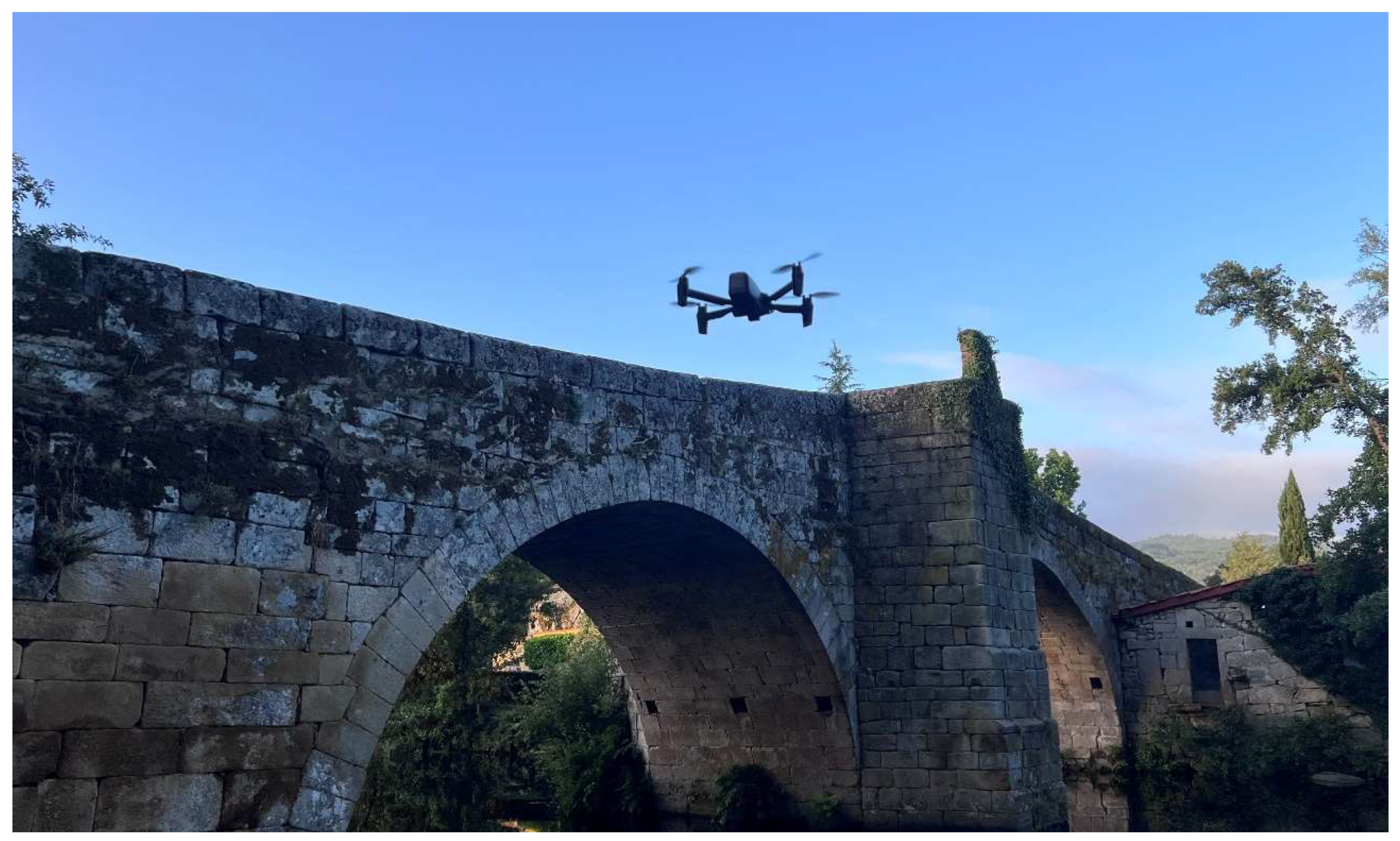
12]. There is no doubt that the fixed-wing drone has great advantages that make it suitable for a multitude of applications, but its inability to perform a vertical takeoff and maintain a stable position in the air makes it unsuitable for the inspection of an old building. Therefore, the type of drone used for the work contemplated here is usually a rotary-wing drone, and more specifically a multirotor (
Figure 5). Multi-rotor drones are drones with multiple propellers (always in pairs) that take off vertically and also have the ability to spin and remain suspended in the air. This makes them ideal for carrying out vertical work and maintaining a fixed, fixed position in suspension, thus allowing for precise analysis.
A purely visual inspection can often be insufficient, as it only analyses the visible elements that make up the buildings. This implies a significant limitation, as there may be damaging phenomena that are invisible to the human eye and therefore escape the recognition and scope of a visual inspection.
Here a relatively new technology emerges and gains importance: thermography. Thermography is a recognition technique based on the detection of radiation emitted by bodies, transforming the captured information into images that incorporate valuable data on the surface temperature of the photographed bodies. Such is its importance that it has not only become the subject of detailed study in the field of heritage and ancient buildings [
13], but has now come to be considered a fundamental instrumental auscultation technique in the field of monument conservation [
14,
15].
A normal camera, such as the one built into any mobile phone today, detects the visible light emitted by objects. This camera is able to capture this visible light on a sheet of paper, thus generating photographs that anyone can see. In other words, a camera detects the visible light emitted by objects and is able to capture it in a photograph. A thermal camera, on the other hand, detects infrared emissions: the frequency of infrared rays is lower than the frequency of visible light, which is why the human eye is unable to detect them. However, these infrared rays can be perceived organoleptically in the form of heat. The human eye is insensitive to the infrared radiation emitted by an object, but the skin is sensitive to this radiation. Therefore, a thermal camera is responsible for capturing the surface temperature of objects and recording it on a thermal image (or thermogram).
For this reason, and in order to have a more complete idea of the functional, resistant and aesthetic state of the Vilanova Bridge, it was decided to also carry out a thermographic analysis, complementary to the visual inspection. For this purpose, a thermographic camera attached to a mobile phone was used.
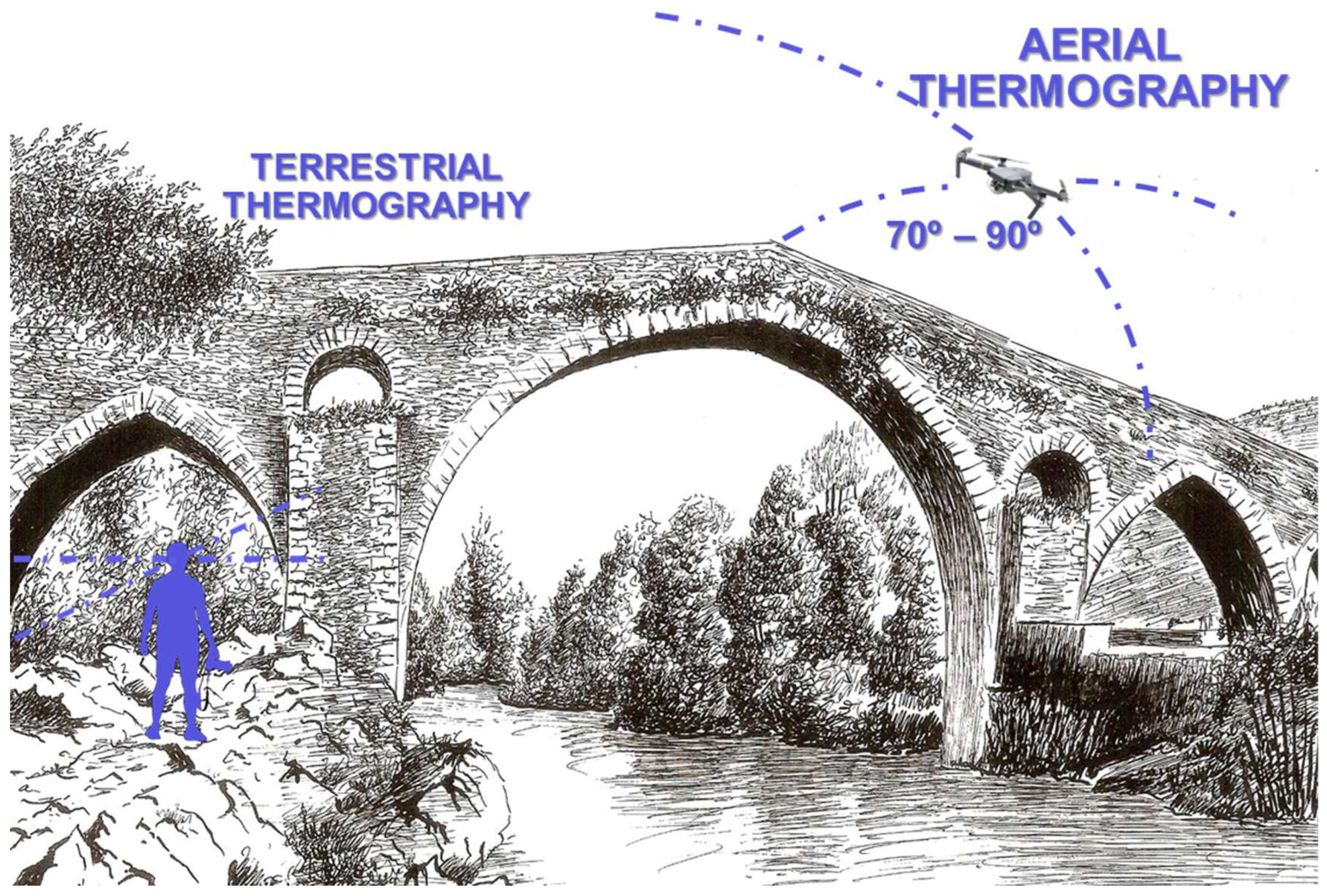
However, with a thermal imaging camera it is often not possible to adopt suitable positions to have the right point of view. For a proper analysis of any thermal anomaly it is recommended that the thermal imaging camera be placed at a viewing angle of between 70° and 90°, measured with respect to the surface being analysed [
16]. The inaccessibility of certain areas of the bridge and the height of the photographer (in our case, 1.85 m) are important limitations: the most delicate area of the bridge was the central area, which is over the river bed.
Due to the small size and low weight of current thermal imaging cameras, any multirotor drone is now capable of carrying a thermal camera. As we have seen with visual inspections, drones, thanks to their versatility of movement and positioning, can position a camera at difficult-to-access viewpoints.
This is how aerial thermography was born. The combination of thermography and aerial piloting of the drone allows us to obtain specific information from a thermal camera from viewpoints that are very difficult to obtain manually. Thus, for example, for an adequate analysis of any thermal anomaly, it is recommended that the thermal camera be positioned with a viewing angle of between 70° and 90°, measured with respect to the surface being analyzed. If a manual camera were used, it would be very difficult to meet this condition; however, a drone with a thermal camera is able to easily meet the condition of having the camera positioned with a viewing angle of between 70° and 90°, measured with respect to the surface being analyzed, overcoming the limitations of terrestrial thermography (
Figure 6).
In aerial thermography, position is no longer a limiting factor. The main limiting factor during the measurement of values is usually the hydrometeorological conditions, because they can significantly influence the accuracy of the measurement. It is advisable to carry out survey campaigns at dawn or dusk, since it is then that it is easier to see the presence of heterogeneous zones, which will dissipate heat in different ways. At this time, the cameras can locate possible construction defects on the materials that make up the monument. In fact, it is ideal that, during the measurement, there is an ambient temperature of 25°C, with a solar intensity of 1,000 Wm-2 and some clouds. In this case, the contrast will be high enough to reflect all the defects. Unfortunately, this is not always possible.
Thus, in aerial thermography, position is no longer a limiting factor. The primary limiting factor during measurement is often hydrometeorological conditions, as they can significantly impact measurement accuracy. Survey campaigns are recommended to be conducted at dawn or dusk, as this is when it is easier to detect heterogeneous areas that will dissipate heat differently. At that time, cameras can locate potential construction defects in the materials making up the monument. Ideally, measurements should be taken when the ambient temperature is around 25°C, with a solar intensity of 1,000 W/m² and some cloud cover. Under these conditions, the contrast will be high enough to reveal any defects. Unfortunately, this is not always possible.
The damage that prompted this investigation, if confirmed, clearly corresponds to an issue with the bridge pier. Specifically, it involves the pier’s foundation. With the tools presented thus far, part of the inspection cannot be conducted due to the presence of the river. This water flow prevents visibility and access to certain elements of the bridge. However, analyzing these elements can be crucial for a complete diagnosis, given the frequency of damage occurring in this type of structure that originates in the foundation [
17,
18].
Any inspection of a civil structure begins with an analysis of the foundation and the base of the construction [
19]. When these elements are visible, a visual inspection can adequately cover their assessment. However, in most cases, these elements are neither visible nor accessible. This limitation means that potential foundation failures can only be detected indirectly, through visible external signs in other parts of the bridge, such as excessive movement, deformation, cracking, etc. [
20,
21,
22]. The displacement observed between the ashlar stones in the upstream spandrel wall and in the downstream cutwater could indicate foundation issues in the pier.
Therefore, the geometric and pathological characteristics of the substructure and superstructure must be carefully monitored. To do this, we carry out visual and thermographic inspections. The first procedure that can (and should) be used to correctly detect problems related to a poor structural response of the foundations is the observation (and subsequent analysis) of the symptoms that may eventually appear in the superstructure as a consequence of the twists, absolute and differential settlements produced in the foundations. For this task, the drone has proven to be a key and very useful instrument.
However, there may be foundation elements that are in poor stability conditions and with reduced levels of safety, without these deficiencies being manifested by obvious external symptoms at the time of the inspection. This is made even worse if one takes into account that there may be a risk of reaching extreme situations or situations of unforeseen instability, as well as large-scale movements or even episodes of collapse, whether partial or even total. Therefore, we can say that it is not possible to carry out a complete inspection, which can provide guarantees of total certainty regarding the real state and stability of an ancient construction, when part of the monument is submerged under water.
The main drawback of localized damage to the foundations of buildings (not only bridges) is the difficulty of visual inspection. If the inspection is carried out during the summer period, the detection of possible problems of degradation of the structural element may be easier. Unfortunately, this is not always possible.
This detection can even be extended to problems that the deterioration of the soil-foundation complex may generate. In the particular case of bridges, the foundations usually start at a certain depth. In addition, the foundations are usually located under water or are invisible for inspection purposes, as they are hidden by sediments. In these circumstances, if what is being undertaken is a purely visual inspection, it is understandable that the inspection is an arduous task (if not overwhelming).
Damage directly suffered by bridge foundations can occur essentially for two reasons [
17,
18,
20,
23,
24]:
due to the degradation of the materials that make up the substructure of the building, and
due to the poor performance of the soil-foundation complex, in response to the different actions to which the complex itself is subjected.
Factors such as the action of water currents on submerged elements or the increase in the hydraulic speed of the current, due to a decrease in the section of the channel or a change in the longitudinal profile, can cause such deficiencies.
Therefore, a detailed visual inspection of the foundation is not enough. To the extent possible, it is important to estimate the type and dimensions of the foundation element, estimate the type of terrain, estimate the longitudinal profile of the river channel, estimate the cross section (upstream and downstream of the construction) and determine the degree of cleaning of the channel and the layout of the drag elements in it. In all these operations, the drone has great shortcomings and limitations.
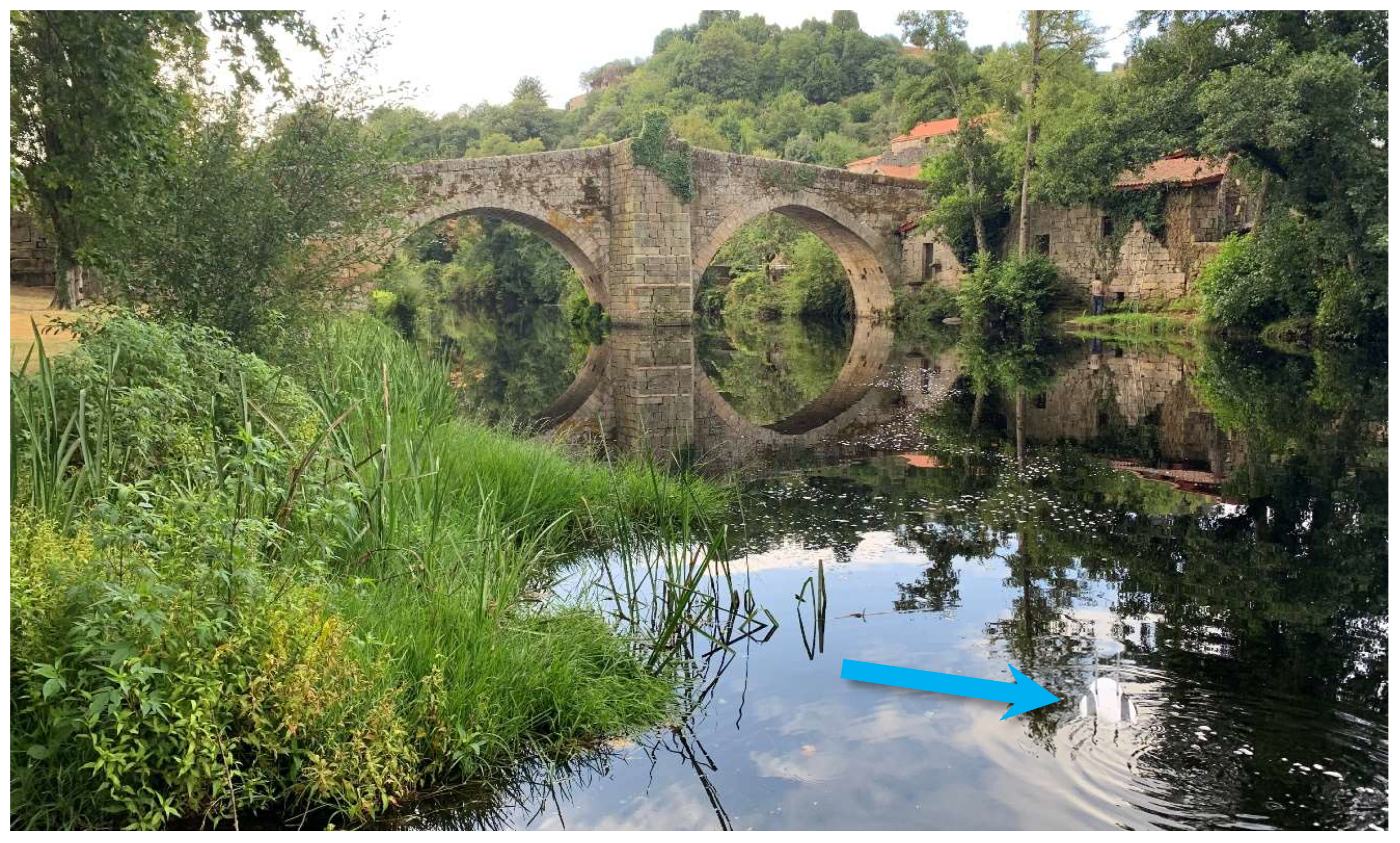
Thus, it is often necessary to resort to the use of special inspection techniques, which allow obtaining sufficient information to have a complete knowledge of the real state of the base of the construction and the detailed bathymetry of the channel beneath it and in its closest surroundings, upstream and downstream of the construction. In accordance with the above, just as the use of a drone was postulated some time ago for carrying out the visual inspection, an equivalent tool has been sought, which allows the recognition of the submerged part of the constructions under analysis: an aquatic drone (
Figure 7 and
Figure 8). A drone model that has already been used for this purpose on an experimental basis [
23,
24] with notable success.
With this underwater drone, it is possible to carry out the inspection of the submerged part of the Vilanova Bridge substructure, given the huge number of catastrophes and bridge collapses linked to failures in their foundations. As with thermography, underwater inspection serves as a complement to visual inspections for which the common drone has proven effective.
Thus, in accordance with the above, to carry out the planned complete inspection, the following microtechnological tools have been used:
- 1.
A simple Flir thermal imaging camera was used to capture photographs and thermograms. Terrestrial thermography operations were carried out with this tool. This camera was connected to an iPhone (iOS system). The characteristic parameters of this thermographic camera are the following:
Thermal Resolution: 80 x 60.
Object Temperature Range —20°C — 120°C.
-
Thermal sensitivity 0.150°C.
Accuracy ±3°C or ±5%, typical Percent of the difference between ambient and scene temperature. Applicable 60s after start-up when the unit is within 15 °C – 35 °C and the scene is within 5 °C – 120 °C.
HFOV 50° ± 1°.
- 2.
A drone Parrot Anafi model (
Figure 5), which incorporated a thermographic camera that could oscillate vertically on its own axis, allowing greater adjustment for the arrangement of the viewing angle between 70° and 90° with respect to the surface to be analysed. Visual inspection and aerial thermography operations were carried out with this tool. This drone has been manufactured in Massachusetts, United States. It weighs 320 g and is used in conjunction with a remote control linked to an iPad (iOS system) for better viewing. The technical characteristics of the thermal imaging camera attached to this drone are the following
Spectral range: Longwave infrared, 8 μm to 14 μm.
Thermal Resolution: 160 x 120.
Thermal sensitivity 0.050 °C.
Object Temperature Range —10°C — 140°C.
HFOV 57°.
- 3.
A PowerVision PowerDolphin PDW10 (4K) underwater drone was used to carry out these inspections (
Figure 7 and
Figure 8). This drone has been manufactured in Beijing, China. It weighs 2268 g and is used in conjunction with a remote control linked to an iPad (iOS system) for better viewing. This underwater drone has a 4K HD camera with multiple resolution settings and the ability to rotate up to 220° on its own axis, allowing it to see above and below the water’s surface. It also has a built-in GPS with bathymetric detection and “return home” functions. It has a two-hour battery life and can reach a maximum speed of 4.50 m/s (16.20 km/h). This drone model was chosen for its simplicity in use and handling, as well as its accessibility. In addition, its low cost made it ideal for this initial research.
5. Conclusions
This work was based on the premise that it is not possible to carry out a complete inspection that can guarantee complete security regarding the real state and stability of an ancient construction, when part of the monument is submerged under water. To do this, and to be able to have a complete diagnosis, an underwater drone has been used as a complement to the aircraft that can carry out visual inspections. This has allowed the recognition of the submerged part of the substructure of a bridge that had allegedly suffered a settlement in its central pier. It has also allowed the study of the bottom of the river basin in the vicinity of the bridge, in order to verify its state in view of the verification of the soil-foundation complex.
During the development of these operations it has been possible to verify that the state of conservation of the submerged elements was notable, with no significant deficiencies or damage related to the degradation of the immersed elements being observed in practically any of them: all the submerged constituent elements were in good condition. The underwater inspection carried out with the drone made it possible to verify that it was not easy to differentiate the structural element of the foundation and the pier of the bridge, something that is very common in old masonry bridges. In any case, the submersible drone made it possible to rule out deficiencies in the soil-foundation interaction and, therefore, any symptoms of settlement in its elements. If there was settlement, as evidenced by the ashlars of the breakwater and the spandrel wall, this settlement occurred some time ago, without having had the slightest subsequent effect on the pier that served as support and, therefore, neither on the rest of the bridge.
The results of the inspection carried out show that the use of appropriate micro-technology allows for a perfectly detailed and complete visual observation of all the submerged elements that make up a masonry bridge. This means that it is possible to avoid having to resort to underwater inspections with divers, which would have been necessary if this instrument had not been available. Therefore, in light of the experience collected here, the following can be concluded:
The underwater drone allows visual recognition of the state of conservation of the constituent material of the submerged elements.
The underwater drone allows the recognition of the material that forms the bed next to the substructure and that, due to the erosive action of the water, can be displaced or altered, causing the undermining of piers or abutments.
The underwater drone allows the verification of the undermining conditions in each pier and abutment, and the estimation of the maximum depth of undermining.
The underwater drone simplifies the planning work of a traditional underwater inspection.
The underwater drone simplifies the field work, in terms of the identification and assessment of deterioration of each of the constituent elements of the monument.
The drone reduces all kinds of risks to the safety of the workers who should collaborate in the underwater inspections, given the inherent danger of the same: with a drone, no worker has to, for example, expose themselves to the risk of drowning inherent to immersion.El drone subacuático permite reconocer el material que conforma el lecho junto a la subestructura y que, por la acción erosiva del agua, puede ser desplazado o alterado, produciendo la socavación de piers o abutments.
The six points above justify a considerable economic saving, which in no case implies a decrease in the quality of work.
Underwater inspection is a very laborious and costly inspection in terms of personnel, logistics and finances, and due to this cost, it is often resorted to when there is no other option. Inspection guides recommend carrying out underwater inspections every five years or even more frequently when the construction requires special monitoring, such as a construction where the foundations are particularly exposed to the action of water, where a rapid evolution of the hydraulic conditions of the river has been observed or when there has been some anthropogenic intervention that may have harmful effects in the area of influence. The appearance of this new aircraft concept, which makes underwater inspection much safer and more accessible, may be a stimulus for these inspections to be carried out more frequently, which will result in greater durability and better conservation of constructions with submerged elements. Aerial thermographic inspection is a complement that can help technicians in charge of heritage inspection and pathological diagnosis to obtain a new, highly relevant point of view, given the angle and distance at which the photographs and measurements are taken. Similarly, when it comes to an inspection of significant dimensions, the time spent on it can be reduced, which will undoubtedly result in economic benefits for all the agents involved.
For its part, thermography (and especially aerial thermography) is a tool that can be used to obtain information regarding the temperature of a heritage element, without the need for physical contact with it. Therefore, it can be said that it is a non-destructive technique that can complement other information (or be complemented by other information) obtained from other sources. This makes it possible to have real data on the state of the different constituent elements of a heritage construction and on the existence of possible damage to said elements. Thermography makes it possible to obtain information to predict future behaviour and thermal anomalies that may occur in some areas of the monument, in order to make an adequate pathological diagnosis or, in the best of cases, to verify the good condition of the ancient construction.
The bridge, despite the visible deformation, is perfectly safe. None of its elements show any significant damage. If the medieval bridge has survived so long, it is because it has been subjected to loads typical of the Middle Ages and, if these loads are not exceeded, it should have no problem surviving for many more years.
Figure 1.
Location of the town of Allariz and the location of the Vilanova Bridge, located there (diagram by the author).
Figure 1.
Location of the town of Allariz and the location of the Vilanova Bridge, located there (diagram by the author).
Figure 2.
General view of the downstream elevation of the Vilanova Bridge (photo by the author).
Figure 2.
General view of the downstream elevation of the Vilanova Bridge (photo by the author).
Figure 3.
General view of the upstream elevation of the Vilanova Bridge, in an image captured by a quadcopter drone (photo by the author).
Figure 3.
General view of the upstream elevation of the Vilanova Bridge, in an image captured by a quadcopter drone (photo by the author).
Figure 4.
Floor plans and elevation of the Vilanova Bridge (diagram by author drawn on a plan by Alvarado, Duran and Nárdiz [
3]).
Figure 4.
Floor plans and elevation of the Vilanova Bridge (diagram by author drawn on a plan by Alvarado, Duran and Nárdiz [
3]).
Figure 5.
General view of the quadcopter drone with a thermal imaging camera used during the inspection, approaching the Vilanova Bridge for reconnaissance (photograph by the author).
Figure 5.
General view of the quadcopter drone with a thermal imaging camera used during the inspection, approaching the Vilanova Bridge for reconnaissance (photograph by the author).
Figure 6.
Comparative analysis between the rigidity of terrestrial thermography and the flexibility of aerial thermography to inspect a medieval bridge (diagram by the author).
Figure 6.
Comparative analysis between the rigidity of terrestrial thermography and the flexibility of aerial thermography to inspect a medieval bridge (diagram by the author).
Figure 7.
General view of the underwater drone used to inspect the Vilanova Bridge. At the time of the photo, the device was being launched towards the submerged elements of the structure for reasons of accessibility (photo by the author).
Figure 7.
General view of the underwater drone used to inspect the Vilanova Bridge. At the time of the photo, the device was being launched towards the submerged elements of the structure for reasons of accessibility (photo by the author).
Figure 8.
Underwater drone surrounding the central pier of the Vilanova Bridge from downstream/the west, inspecting the river bottom around the cutwater (photo by the author).
Figure 8.
Underwater drone surrounding the central pier of the Vilanova Bridge from downstream/the west, inspecting the river bottom around the cutwater (photo by the author).
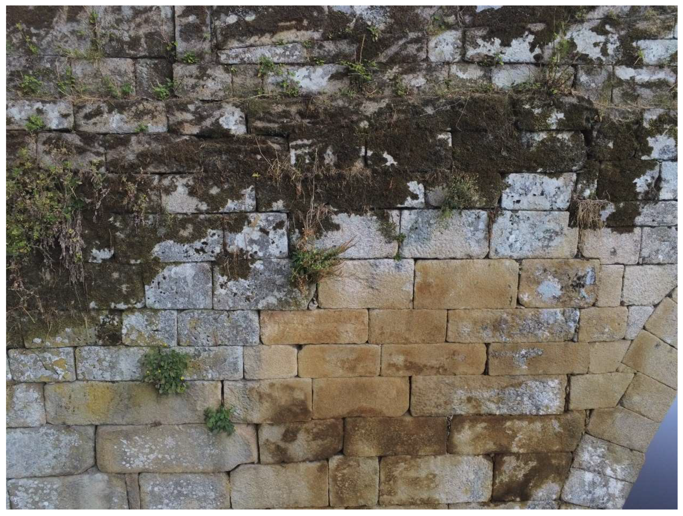
Figure 9.
View of the external spandrell wall, in a photographic image taken with the drone, where we can see the abundant presence of vegetation and degradation of the stone (photograph by the author).
Figure 9.
View of the external spandrell wall, in a photographic image taken with the drone, where we can see the abundant presence of vegetation and degradation of the stone (photograph by the author).
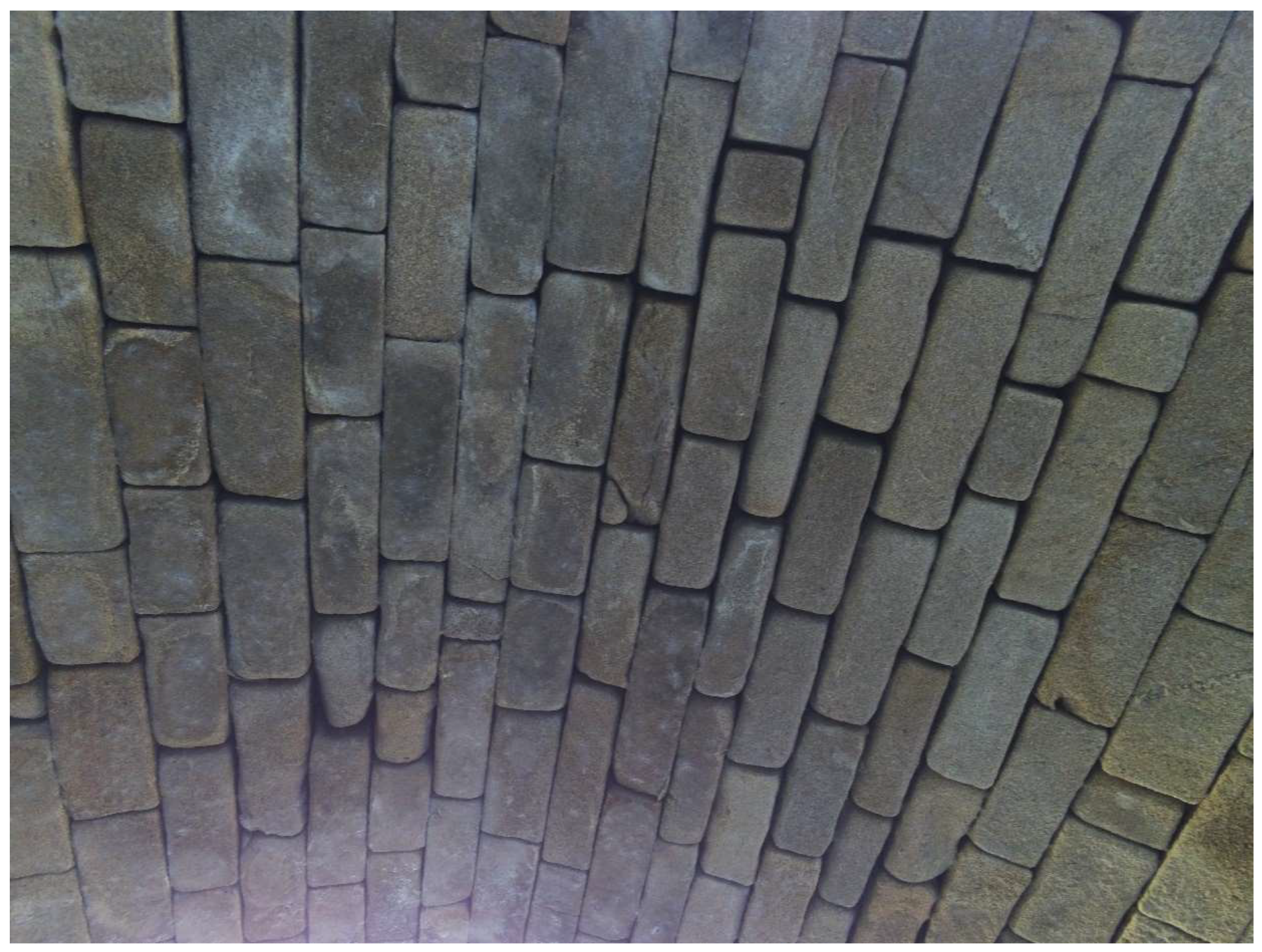
Figure 10.
View of the intrados of the first vault, in a photographic image taken with the drone (photograph by the author).
Figure 10.
View of the intrados of the first vault, in a photographic image taken with the drone (photograph by the author).
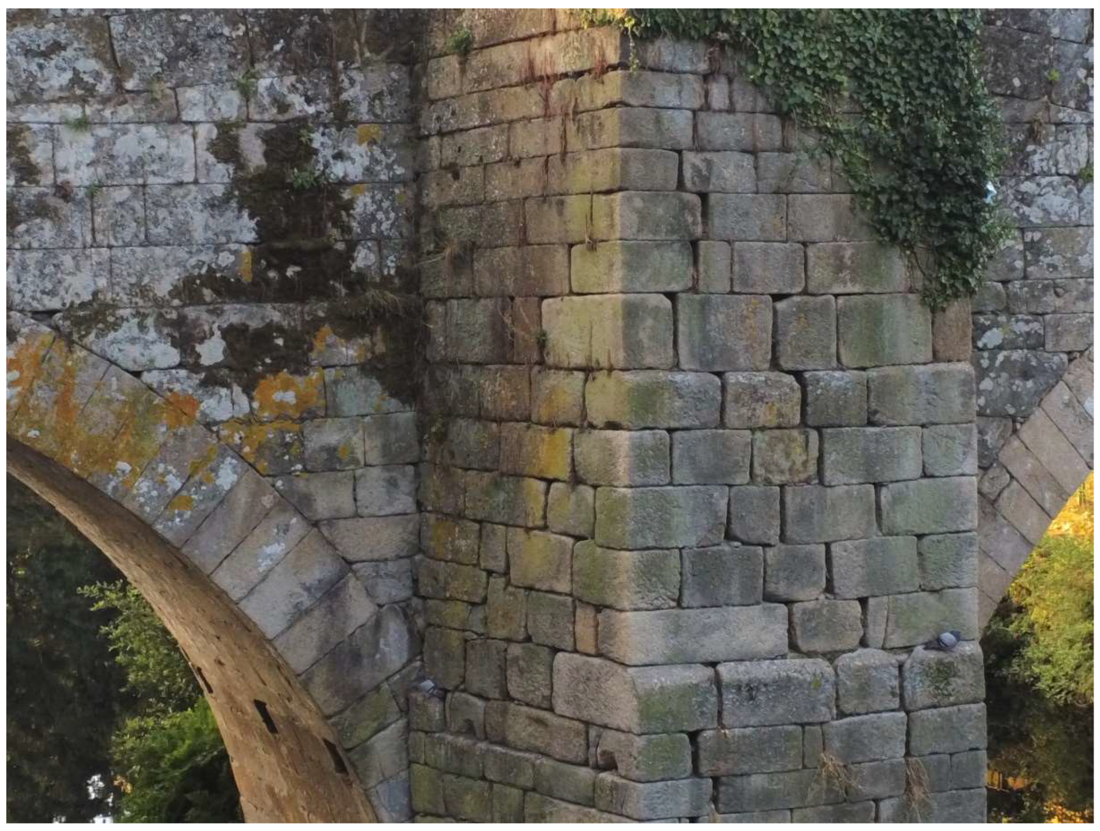
Figure 11.
Partial view of the cutwater that rises to the road, downstream of the bridge, where the separation between some ashlars can be seen in an image captured with the drone (photograph by the author).
Figure 11.
Partial view of the cutwater that rises to the road, downstream of the bridge, where the separation between some ashlars can be seen in an image captured with the drone (photograph by the author).
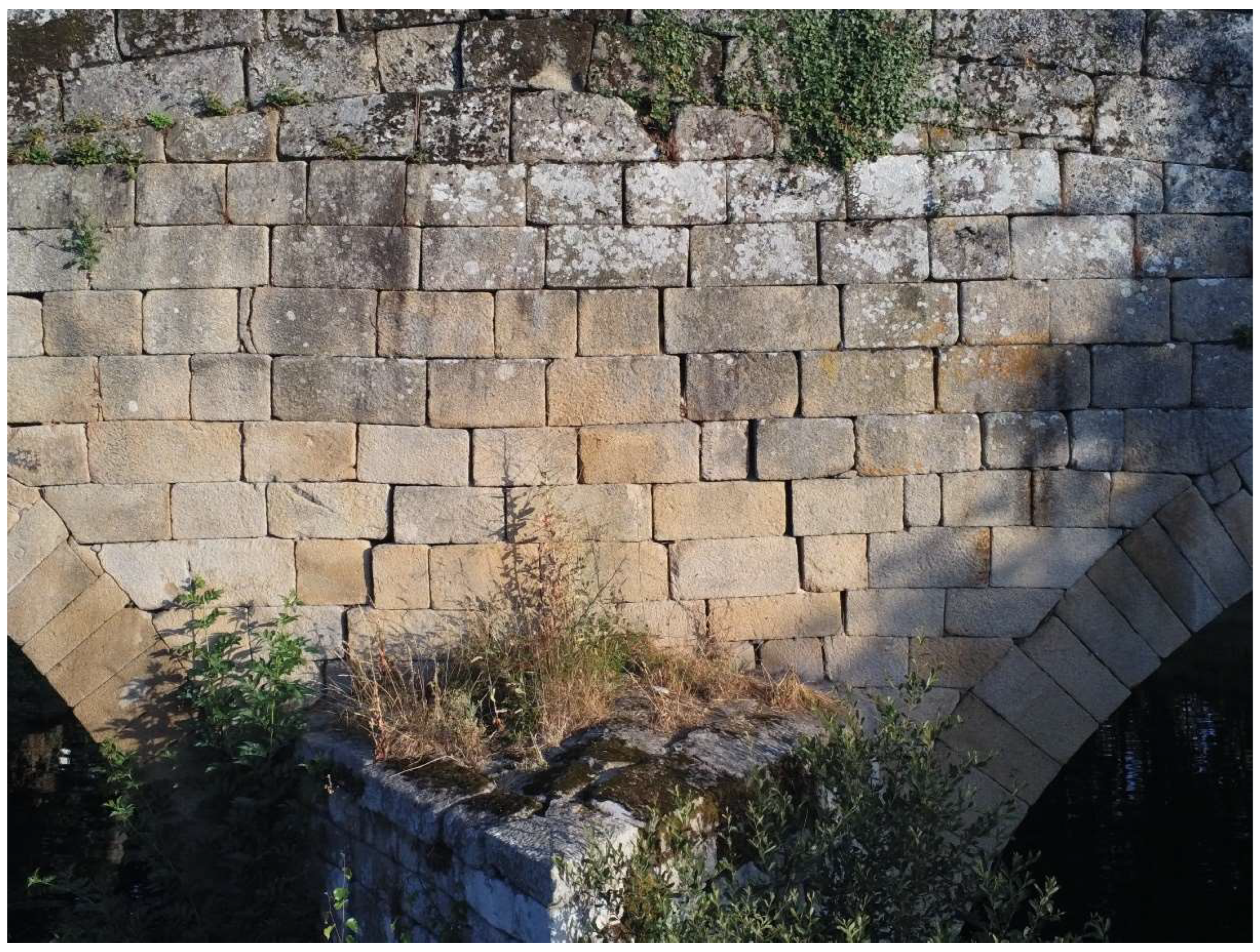
Figure 12.
View of the central area of the spandrel wall, upstream of the bridge just above the starling, where the separation between some ashlars can be seen, in an image captured with the drone (photograph by the author).
Figure 12.
View of the central area of the spandrel wall, upstream of the bridge just above the starling, where the separation between some ashlars can be seen, in an image captured with the drone (photograph by the author).
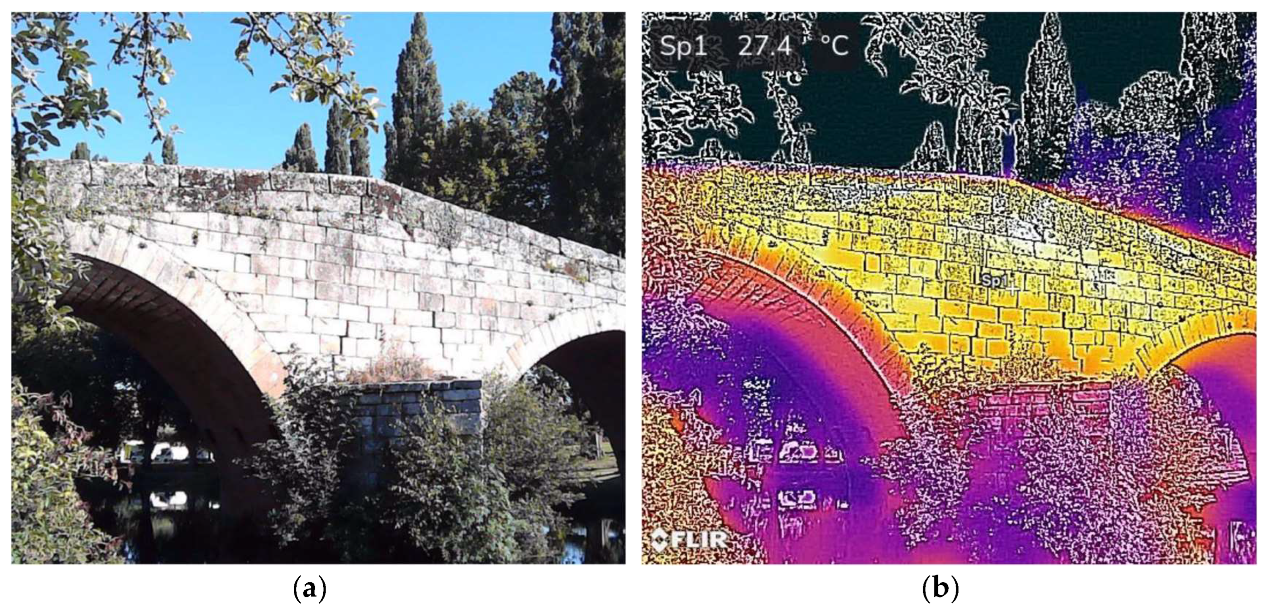
Figure 13.
General view of the upstream elevation of the Vilanova Bridge: (a) image captured by a camera; (b) thermogram on the loft photograph (photographs by the author).
Figure 13.
General view of the upstream elevation of the Vilanova Bridge: (a) image captured by a camera; (b) thermogram on the loft photograph (photographs by the author).
Figure 14.
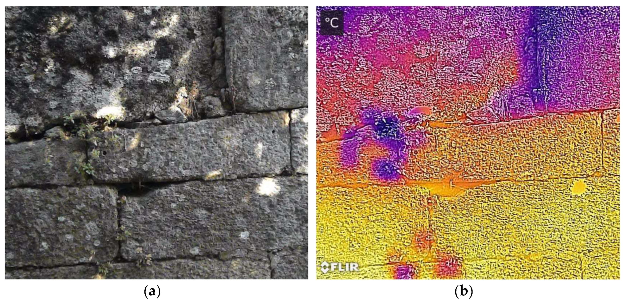
Detail of the southeast abutment wall of the Bridge: (a) image captured by a camera, where different ashlars can be seen; (b) thermogram on the same photograph (photographs by the author).
Figure 14.
Detail of the southeast abutment wall of the Bridge: (a) image captured by a camera, where different ashlars can be seen; (b) thermogram on the same photograph (photographs by the author).
Figure 15.
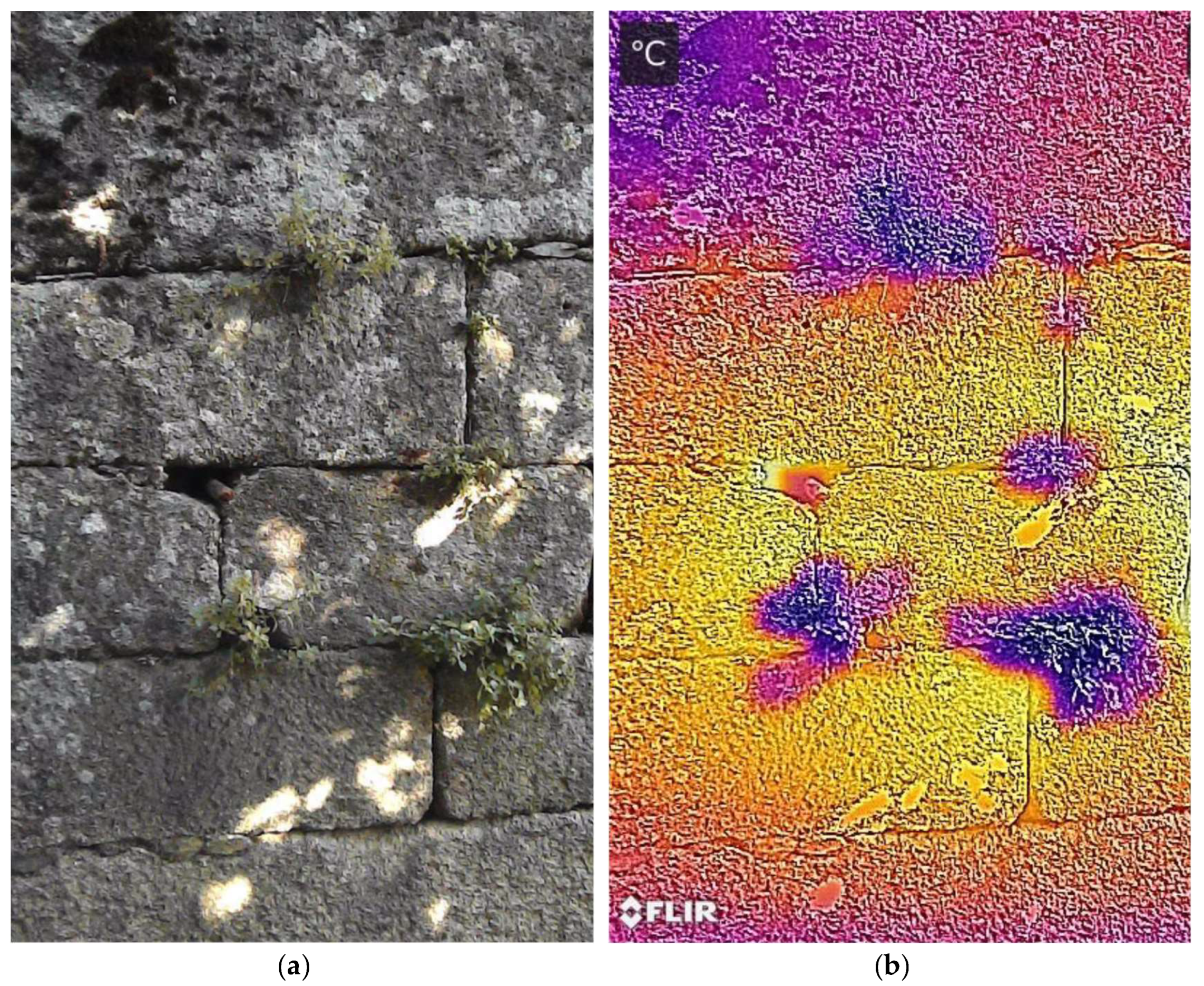
Detail of the southwest abutment wall of the Bridge: (a) image captured by a camera, where different ashlars can be seen; (b) thermogram on the same photograph (photographs by the author).
Figure 15.
Detail of the southwest abutment wall of the Bridge: (a) image captured by a camera, where different ashlars can be seen; (b) thermogram on the same photograph (photographs by the author).
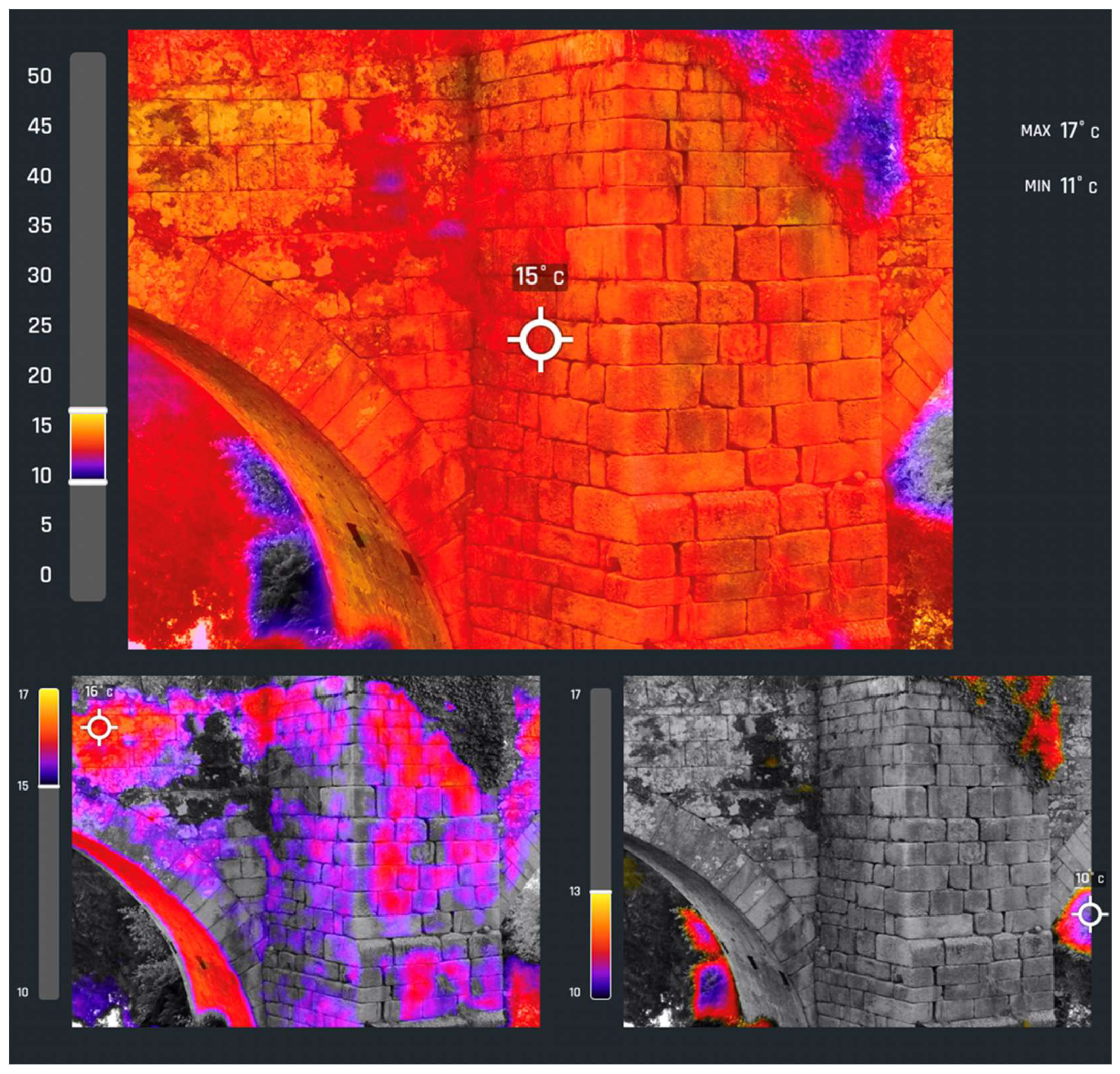
Figure 16.
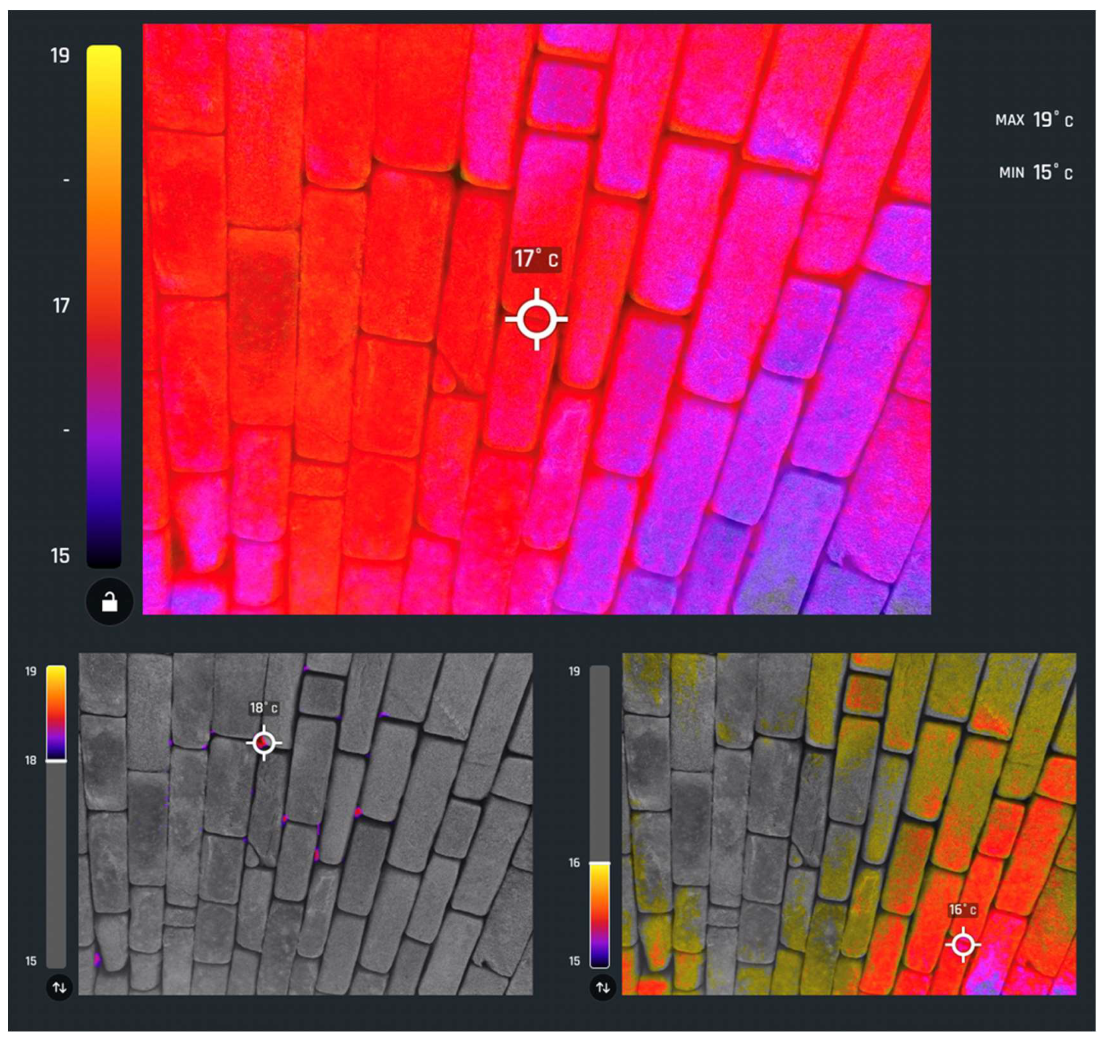
Thermograms of the intrados of the vault, marking the points of maximum temperature (bottom left) and the points of minimum temperature (bottom right).
Figure 16.
Thermograms of the intrados of the vault, marking the points of maximum temperature (bottom left) and the points of minimum temperature (bottom right).
Figure 17.
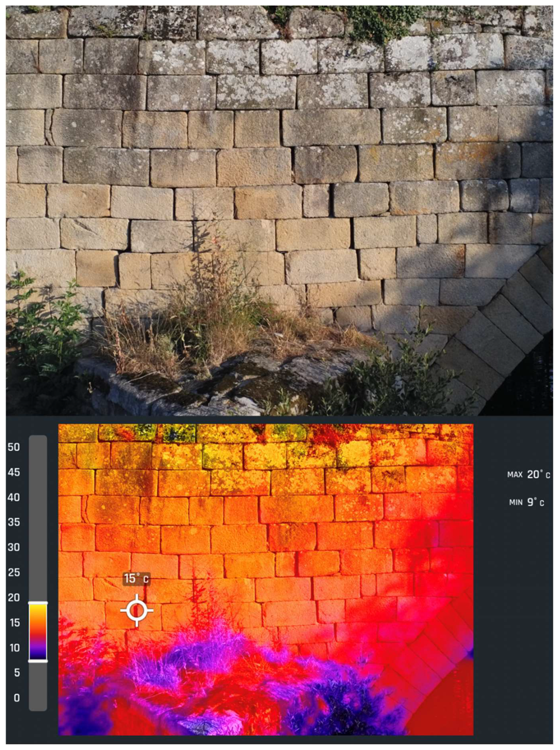
Photograph (upper figure) and thermogram (lower figure) of the central area of the spandrel wall, upstream of the bridge just above the starling (photograpsh by the author).
Figure 17.
Photograph (upper figure) and thermogram (lower figure) of the central area of the spandrel wall, upstream of the bridge just above the starling (photograpsh by the author).
Figure 18.
Thermograms of the cutwater downstream of the bridge, marking the points of maximum temperature (bottom left) and the points of minimum temperature (bottom right) to study the separation between some ashlars (photographs by the author).
Figure 18.
Thermograms of the cutwater downstream of the bridge, marking the points of maximum temperature (bottom left) and the points of minimum temperature (bottom right) to study the separation between some ashlars (photographs by the author).
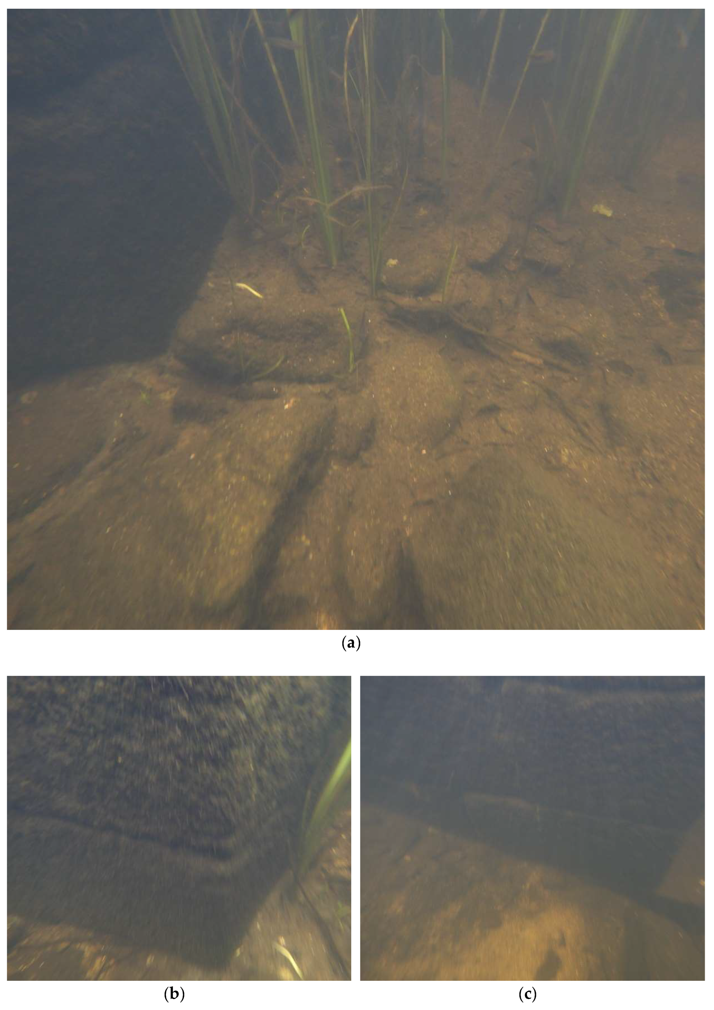
Figure 19.
Underwater drone images showing: (a) the riverbed around the pier; (b) the status of a fragment of the lower part of the pier; (c) another fragment of the lower part of the element inspected (photos by the author).
Figure 19.
Underwater drone images showing: (a) the riverbed around the pier; (b) the status of a fragment of the lower part of the pier; (c) another fragment of the lower part of the element inspected (photos by the author).
