Preprint
Article

Nonlinear Dynamic Stability Analysis of Seaplanes in Waves Using Poincaré–Lindstedt Perturbation Method

Altmetrics

Downloads

36

Views

37

Comments

0

A peer-reviewed article of this preprint also exists.

This version is not peer-reviewed

Submitted:

31 October 2024

Posted:

31 October 2024

You are already at the latest version

Alerts
Abstract
Abstract: In this study, we present an analytical tool that can be used to predict the nonlinear structural response of seaplanes advancing through sinusoidal head-sea waves. Seaplanes exhibit a unique instability phenomenon known as porpoising, which is an oscillatory motion along the heave and pitch axes that can cause serious structural damage. The heaving and pitching equations of motion are presented in the form of coupled, forced, and nonlinear Duffing-type equations with cubic nonlinearity. The analytical model developed in this study leverages the Poincaré–Lindstedt perturbation method to express the amplitude and frequency of motion in terms of all physical parameters. The accuracy and reliability of the proposed model were validated through computational fluid dynamics (CFD) simulations based on incompressible unsteady Reynolds-averaged Navier–Stokes (RANS) equations. The results show a strong agreement between the analytical tool and the CFD simulations, with minor discrepancies due to assumptions inherent in the 2D simulations, particularly the assumption that seawater only passes beneath the hull, resulting in increased buoyancy forces and reduced damping. This study offers a novel and practical method for predicting the dynamic stability of seaplanes under realistic sea conditions, potentially enhancing safety and operational efficiency by mitigating the risks associated with porpoising.
Keywords: 
Subject: Engineering  -   Marine Engineering

1. Introduction

With the increasing number of passengers and the need for more freight transport around the world, logistics and transport companies are pressured to increase their number of flights. However, this has led to a major increase in global air traffic, and the aviation industry is under pressure to reduce noise and emissions. One of the potential solutions to this issue is to build airports away from populated areas in offshore locations. This means moving the take-off and landing paths over water. However, the cost of land reclamation and the need for new terminal buildings and pathways to be constructed are very high. An alternative to expensive infrastructure would be the use of a hybrid configuration that can reach high speeds while carrying a heavy payload. The introduction of high-speed planing hulls has led to the development of a hybrid configuration known as the seaplane, which is fast, agile, and capable of covering a wide range of applications because it combines the characteristics of aeroplanes and hydroplanes. The configuration of the seaplane is started as a ship, but with the advantage of using the aerodynamic phenomenon known as the ground effect to fly just above the surface of the water.
When a craft flies next to the surface of the water or ground, it is influenced by the surface effect of aero-hydrodynamics, which leads to a high lift-to-drag ratio. The deceleration of air trapped between the ground and the wing surface causes a significant increase in the pressure on the under-surface of the wing [1]. Thus, the ground effect (GE) can be defined as the increase in the lift-to-drag ratio of a lifting surface flying at a small relative distance from the underlying surface [2]. This technology was most notably used in the development of the “Ekranoplan” designed in the Soviet Union in the beginning of the 1960s [1,2,3].
Seaplanes have a unique instability phenomenon called porpoising, which, according to Faltinsen [4], can be defined as a periodic, bounded vertical motion that a craft might exhibit at certain speeds, as illustrated in Figure 1. This phenomenon can be seen as an oscillatory motion in the heave and pitch axes and can cause severe damage to the structure of the craft [5]. In some cases, if the hull leaves the water and returns with a negative trim angle, the craft will submarine [6]. Porpoising can be fatal, even in calm water, because the loss of longitudinal stability can cause self-induced heave and pitch oscillations (porpoising) and the submergence of the bow area [7].
It is of great importance to study the response of the coupled motions of an object when it is subjected to an external periodic force. Such a set-up finds applications in resonance vibrations, similar to what is seen when a seaplane is accelerating to take-off. This could lead to minimising unwanted resonance and avoiding chaos [8]. In addition, the exact analytical solutions of the nonlinear, coupled, and forced equations of motion are very helpful for performing comprehensive analyses. These solutions can be used to capture the main nonlinear phenomena, such as nonlinear resonance and chaos, that characterise these systems with respect to the linear ones. In contrast to the numerical solutions, which can be useful for investigating a specific case, the analytical solution can be helpful for conducting a detailed parametric analysis aimed at understanding the whole system’s behaviour. This is needed in the pre-design of any mechanical structure that interacts with a moving fluid [9]. Hence, understanding the role of coupling and nonlinearity on system behaviour could enhance the dynamic stability of seaplanes and provide insight into key design parameters. In fact, predicting the take-off performance by combining aerodynamic and hydrodynamic calculations is a major challenge in seaplane design [10]. The structural design of a sea-craft requires the evaluation of its motions and wave-induced pressure distributions over the hull in wavy sea conditions. Thus, a nonlinear, time-dependent seakeeping solution must simulate, with sufficient accuracy and efficiency, the seakeeping behaviour of a sea-craft in wave trains that may be several hours long in duration [11]. With this goal in mind, the development of a nonlinear periodic solution was initiated.
Most studies conducted to date on the dynamic stability of seaplanes have been experimental or numerical in nature. For instance, Guo et al. [10] used the volume-of-fluid (VOF) approach to numerically simulate the air–water flow field to study the resistance characteristics and attitude of a seaplane at various take-off speeds. They concluded that a seaplane's trim angle should be operated in an ideal trim range, typically between 4° and 6°, to minimise hydrodynamic resistance. Song et al. [12] conducted a numerical study to understand the characteristics of a seaplane’s take-off performance. The study only focused on the suction force, pressure, free surface, and motion of the seaplane model to understand the characteristics of the planing motion of the seaplane when moving through waves of different velocities, wavelengths, and heights. A two-dimensional numerical investigation was performed using the VOF approach proposed by Xie et al. [13]. The latter used a gas–liquid two-phase model to simulate complex fluid fluxes, with the air–water interface captured using the VOF technique. Their findings elucidated the mechanism of complicated flows under the influence of the bottom cabin and inclined postures. After conducting a comprehensive review of the academic literature on seaplane hydrodynamics, Tavakoli et al. [14] concluded that more work needs to be conducted on mathematical models, particularly those that simulate manoeuvring motions, to fully account for the challenges of operating in a real-world maritime environment. Zhou et al. [15] stated that the majority of the present research on seaplane planing in waves is still concentrated on experiments and numerical simulations in calm water or under low-wave conditions. According to Wang et al. [16], it is no longer difficult to forecast the porpoising conditions for a specific sea-craft, experimentally or numerically. The challenge is finding out how to solve the porpoising problem, which is achievable with an understanding of the nonlinear behaviour of sea-crafts accelerating on a wavy sea surface. Zheng et al. [17] used a modified two-phase flow solver in OpenFOAM to simulate the porpoising phenomenon of a large seaplane with four turbines during take-off. They discovered that heaving and pitching oscillations are primarily determined by the hydrodynamic force, with the aerodynamic force playing an auxiliary role. A numerical study by Zha et al. [18] investigated the water-landing behavior of seaplanes and concluded that careful control of seaplane motion is essential to prevent potential damage from overwashing events. After thoroughly reviewing the methods used in seaplane hydrodynamic design, Morabito [19] stated that, because the majority of the research in this field dates back to the 1940s, studying the hydrostatic and hydrodynamic challenges associated with seaplane design is currently an important endeavour.
This study aimed to present an analytical tool that can be used to predict the nonlinear motion of seaplanes advancing through head-sea waves. The analytical tool is a system of coupled, nonlinear heaving and pitching equations of motion, which are assumed to be externally excited by a sinusoidal head-sea wave. These equations are presented in the form of a system of coupled Duffing equations with cubic nonlinearity. The focus is on heave and pitch motions because, at a speed-to-length ratio of less than 4 (take-off and landing speeds), the hydrodynamic coefficients associated with motions in other directions are neglected [20]. Hence, the dynamic stability of seaplanes during take-off and landing was examined from heaving and pitching motions. The analytical tool was validated using computational fluid dynamics (CFD) simulations performed on Ansys Fluent, using the VOF method, as the flow was two-phase. Analytical data for aero-hydrodynamics and flight mechanics have a direct impact on safety and reliability and can assist in enhancing both. This provides an opportunity to investigate the nature of the nonlinearity derived directly from motion physics. This should provide a deeper understanding of the nonlinear phenomenon associated with motion across waves, by explaining the effect of the nonlinear and coupling coefficients on the magnitude of the external force/moment. This study is the first of its kind to use the coupled nonlinear Duffing equation to describe the heaving and pitching motions of seaplanes advancing through head-sea waves. A closed-form analytical solution to the equations of motion, describing the structural response of the seaplane hull, is also presented in this study.

2. Mathematical Formulation

Coupled Duffing oscillators were previously investigated analytically in [8,9,21,22,23]. In all previous works, the attention has been focused on the route to chaos and the frequency response. No attempts have been made to obtain an exact, closed-form analytical solution representing the heaving and pitching responses of a seaplane advancing through head-sea waves, which was the aim of this work. The chaos theory is one of the most significant achievements in nonlinear science. The Duffing equation is associated with the mathematical chaotic behaviour. This chaotic behaviour exists in many natural systems, such as weather and climate systems [24]. It also occurs spontaneously in systems with artificial components, such as road traffic. Chaos theory has been applied in several other disciplines, including meteorology, sociology, and environmental sciences. Chaos is defined as a periodic long-term behaviour in a deterministic system that exhibits a sensitive dependence on the initial conditions [25]. Three properties must exist in a dynamical system for it to be classified as chaotic:
  • It must exhibit periodic long-term behaviour, meaning that the solution of the system settles into an irregular pattern as t . The solution either does not repeat or oscillates in periodically.
  • It is sensitive to the initial conditions. This means that any small change in the initial condition can change the trajectory, which may result in significantly different long-term behaviour.
  • It must be “deterministic”, which means that the irregular behaviour of the system is due to the nonlinearity of the system, rather than external forces.
Thus, Duffing oscillators find applications in chaos theory, which is a field of study in mathematics that investigates the behaviour of dynamical systems that are highly sensitive to the initial conditions. Small differences in the initial conditions (such as rounding errors in the numerical computation) yield widely diverging outcomes for such dynamical systems, rendering long-term predictions generally impossible [25]. There are several analytical methods that can be used to solve the Duffing equation in its various forms, such as the method of multiple scales [26], the Bogolubov–Mitropolski method [27], He’s energy balance method [28], the global error minimisation method [29], the variational iteration method [30], the Jacobi elliptic functions method [31], the homotopy perturbation method [32], and the Poincaré–Lindstedt method [33].
Several physical problems faced by engineers today demonstrate certain fundamental features, such as nonlinearities, that prevent exact analytical solutions. Thus, perturbation methods are used to obtain information regarding the solutions of nonlinear equations. The solution is presented in the form of convergent power series expansions with respect to a small dimensionless parameter that is of the same order of nonlinearity and amplitude of motion [34]. The Poincaré–Lindstedt method is used to uniformly approximate periodic solutions to ordinary differential equations. This method eliminates the secular terms arising from the straightforward application of the regular perturbation theory to weakly nonlinear equations [35]. Secular terms are those that grow without bounds. These terms have a singularity point at which a given mathematical object is not defined [35].
The Poincaré–Lindstedt method was adopted in this research to find a closed-form solution to the coupled equations of motion because it is used to obtain periodic solutions to nonlinear differential equations. It describes the period of the unstable motion of seaplanes such that porpoising can be predicted analytically. The use of this technique leads to an expression for the desired solution in terms of a formal power series with a small parameter ( ε ), known as a perturbation series, that quantifies the deviation from the exact solvable problem [36,37,38].

2.1. Heave and Pitch Equations of Motion

The equations of motion for a seaplane advancing at a constant forward velocity with an arbitrary heading in regular sinusoidal sea waves are presented in this section. The performance of the seaplane is presented using a six-DOF (degrees of freedom) system. Considering that the responses are linear and harmonic, the six linear equations of motion can be written using the subscript notation as follows [4]:
k = 1 6 M j k + A j k ƞ ¨ k + B j k ƞ ˙ k + C j k ƞ k = F j e i ω t   ,
where
  • j = 1 6 .
  • m j k is the component of the generalised mass matrix of the craft in the j t h direction owing to the k t h motion.
  • A j k is the added-mass coefficient in the j t h direction due to the k t h motion.
  • B j k is the damping coefficient in the j t h direction due to the k t h motion.
  • C j k is the hydrostatic restoring force coefficient in the j t h direction due to the k t h motion.
  • F j is the complex amplitude of the exciting forces and moments in the j t h direction.
Heaving and pitching due to moving through head-sea waves are oscillatory motions along the vertical and sagittal axes, as illustrated in Figure 2. Heaving can be defined as the translational (linear) motion in the vertical direction, while pitching is the rotational (angular) motion of the centre of gravity of the aircraft [39].
The heaving and pitching system of seaplane motion behaves like a two-degrees-of-freedom spring-mass system. According to Faltinsen [4], this assumption is clear when a craft model is given heave or pitch displacements from its equilibrium position; it rapidly oscillates several times before it comes to rest. Therefore, the resulting equations for the heave and pitch motions of the seaplane can be expressed as follows:
m + A 33 ƞ ¨ 3 + A 35 ƞ ¨ 5 + B 33 ƞ ˙ 3 + B 35 ƞ ˙ 5 + C 33 ƞ 3 + C 35 ƞ 5 = F t ,
A 53 ƞ ¨ 3 + ( A 55 + I 55 ) ƞ ¨ 5 + B 53 ƞ ˙ 3 + B 55 ƞ ˙ 5 + C 53 ƞ 3 + C 55 ƞ 5 = M t .
Subscripts 3 and 5 represent the heave and pitch motions, respectively. In addition, u is the heave translational displacement, and v is the pitch angular displacement. F ( t ) is the external excitation force and M ( t ) is the external excitation moment. Both quantities were assumed to be caused by sinusoidal waves. Hence, the excitation forces and moments can be expressed as follows:
F t = F cos ω t ,   M t = M cos ( ω t + φ ) .
Both the time-dependent sinusoidal force and moment functions oscillate at an external excitation frequency ω . Here, t denotes time, F represents the amplitude of the force, M is the amplitude of the moment, and φ is the phase angle, indicating a phase shift in the moment relative to the force.
The hydrostatic restoring force coefficient (buoyancy), hydrodynamic coefficients (added mass and damping), and external forces and moments (amplitudes and frequency) acting on a planing hull were calculated using strip theory. This theory utilises the integration of the hydrodynamic pressure acting on the wetted surface of the planing hull to obtain the forces and moments. The calculation of the coefficients is discussed in detail in Section 4.1.
The general equations of the heave and pitch motions of seaplanes were reduced to Duffing oscillator equations by assuming that the restoring forces behave according to Hooke’s law but have a nonlinear nature (cubic nonlinearity). The system is excited by a sinusoidal head-sea wave, and the damping effect is negligible because the hydrodynamic coefficients associated with damping are much smaller than the added mass and restoring force coefficients. This is because the damping coefficients are functions of frequency and speed, whereas the added mass and restoring force coefficients are functions of the seaplane mass [40]. In addition, the pitch’s angular acceleration was neglected in the heave equation, and the heave translational acceleration was neglected in the pitch equation. Nevertheless, the elastic deformation of the rigid body was neglected because the system of equations of motion was formed using Lagrangian mechanics, in which the system is assumed to be conserved. Finally, a mathematical model was developed to predict porpoising when the craft is under maximum buoyancy support; hence, the hydrostatic restoring force is dominant. Taking this into consideration, this two-degrees-of-freedom system can be modelled using two coupled second-order nonlinear differential equations with the following forms:
u ¨ + ω 0 2 u + a 1 v + a 2 u 3 = F 1 cos ω t ,
v ¨ + ω 0 2 v + b 1 u + b 2 v 3 = M 1 cos ω t + M 2 sin ω t ,
where
  • a 1 is the pitch coupling term coefficient.
  • a 2 is the heave nonlinear term coefficient.
  • b 1 is the heave coupling term coefficient.
  • b 2 is the pitch nonlinear term coefficient.
  • F 1 is the heave amplitude.
  • M 1 and M 2 are the pitch amplitudes.
  • ω 0 is the natural frequency.
  • ω is the external excitation frequency.
Equations (5) and (6) are harmonically excited Duffing oscillator equations. They can be solved using the Poincaré–Lindstedt method by introducing a new, small, non-dimensional parameter ( ε ) into the equations. This was achieved by assuming that the nonlinearity, coupling, and excitation force/moment are small relative to the harmonic motion and that they appear in the same order in each equation. In addition, ( ε ) can be used as a measure of the strength of the nonlinearity. Hence, a small parameter ( ε ) was introduced, and Equations (5) and (6) can be rewritten as follows:
u ¨ + ω 0 2 u + ε a 1 v + ε a 2 u 3 = ε F 1 cos ω t ,
v ¨ + ω 0 2 v + ε b 1 u + ε b 2 v 3 = ε M 1 cos ω t + ε M 2 s i n ω t .

2.2. Amplitude Equations

We next turned to the question of determining an expression for the amplitude and frequency of porpoising oscillations in terms of the nonlinearity, coupling, and external forcing parameters. The frequency of the system ω can be explicitly presented in the differential equation by introducing the following transformation:
τ = ω n ω 0 t .
The frequency of the forcing term was initially assumed to be unknown, but near a multiple of the natural frequency, ω 0 . To account for this, n was introduced to define the order of resonance, allowing the solution to cover various cases (i.e., different orders of resonance). By applying the chain rule, the equations were transformed as follows:
ω 2 u + ω 0 2 u + ε a 1 v + ε a 2 u 3 = ε F 1 cos τ ,
ω 2 v + ω 0 2 v + ε b 1 u + ε b 2 v 3 = ε M 1 cos τ + ε M 2 s i n τ ,
where the prime symbol indicates the derivative with respect to the re-scaled time variable τ . An unknown frequency of the system appeared in the differential equations. Hence, approximate solutions were obtained for both equations in the form of power series expansions in terms of ε . In other words, the following were introduced:
u = u 0 τ + ε u 1 τ + ε 2 u 2 τ + O ε 3 ,
v = v 0 τ + ε v 1 τ + ε 2 v 2 τ + O ε 3 ,
ω = n ω 0 + ε ω 1 + ε 2 ω 2 + O ε 3 .
The first term in the expansion represents the linear solution of the equation, also referred to as the leading-order term. In this study, the leading-order frequency, ω 0 , was set to unity, representing the natural frequency of the system. Substituting Equations (12), (13), and (14) into Equations (10) and (11) yielded the following:
[ ω 0 + ε ω 1 + ε 2 ω 2 ] 2 u 0 + ε u 1 + ε 2 u 2 + ω 0 2 u 0 + ε u 1 + ε 2 u 2 + ε a 1 v 0 + ε v 1 + ε 2 v 2 + ε a 2 [ u 0 + ε u 1 + ε 2 u 2 ] 3 = ε F 1 cos τ ,
[ ω 0 + ε ω 1 + ε 2 ω 2 ] 2 v 0 + ε v 1 + ε 2 v 2 + ω 0 2 v 0 + ε v 1 + ε 2 v 2 + ε a 1 u 0 + ε u 1 + ε 2 u 2 + ε a 2 [ v 0 + ε v 1 + ε 2 v 2 ] 3 = ε M 1 cos ( τ ) + ε M 2 sin τ .
Separating the terms of the same order and eliminating the terms of order O ( ε 3 ) yielded the following equations:
  • Heaving terms:
u 0 + u 0 = 0 ,
ω 0 2 u 1 + u 1 + 2 ω 0 ω 1 u 0 + a 2 u 0 3 = F 1 cos τ ,
ω 0 2 u 2 + u 2 + 2 ω 0 ω 1 u 1 + 2 ω 0 ω 2 u 0 + ω 1 2 u 0 + 3 a 2 u 0 2 u 1 = 0 .
  • Pitching terms:
v 0 + v 0 = 0 ,
ω 0 2 v 1 + v 1 + 2 ω 0 ω 1 v 0 + a 2 v 0 3 = M 1 cos τ + M 2   s i n τ ,
ω 0 2 v 2 + v 2 + 2 ω 0 ω 1 v 1 + 2 ω 0 ω 2 v 0 + ω 1 2 v 0 + 3 a 2 v 0 2 v 1 = 0 .
The leading-order solutions of the two equations were assumed to have the following form:
u 0 = A c o s ω 0 τ , v 0 = B c o s ω 0 τ + C s i n ω 0 τ .
The corrections to the linear solution were determined in the course of the analysis by requiring the expansion of u and v to be uniform for all τ . However, the particular solution of the first-order terms of u and v contains secular terms that make the expansion non-uniform. To achieve uniform expansion, the secular terms in u 1 , v 1 , u 2 , and v 2 must be eliminated. To this end, the coefficients of the secular terms were set to zero to find expressions for the first-order frequency ω 1 . Thus, only the inhomogeneous terms in Equations (18), (19), (21), and (22) governing u 1 , v 1 , u 2 , and v 2 were inspected. This resulted in the expansions being uniform for all first- and second-order solutions because secular terms did not appear in them. Removing all secular terms up to the first order required satisfying the following system of equations:
a 1 B F 1 = 0 ,
3 a 2 A 3 + 4 a 1 C 8 A ω 0 ω 1 = 0 ,
3 b 2 B 3 + 3 b 2 C 2 B 8 B ω 0 ω 1 4 M 1 = 0 ,
4 A b 1 + 3 b 2 C 3 + 3 b 2 B 2 C 8 C ω 0 ω 1 4 M 2 = 0 ,
while A satisfied the following cubic polynomial:
3 F 1 b 1 2 b 2 F 1 2 a 1 2 a 2 M 1 2 A 3 6 b 1 b 2 F 1 3 M 2 A 2 + 4 a 1 2 b 1 F 1 2 M 1 4 a 1 3 M 1 3 + 3 b 2 F 1 3 M 1 2 + 3 b 2 F 1 3 M 2 2 A 4 a 1 2 F 1 2 M 1 M 2 = 0 .
A represents the amplitude of the external force, which is the amplitude of the sea wave. The nonlinear coefficients a 2 and b 2 were obtained from the polynomial, assuming in the first approximation that both coefficients are equal. The other terms were obtained from the following equations:
a 1 = C 35 m + A 33 ,
b 1 = C 53 A 55 + I 55 ,
F 1 = F a m + A 33 ,
M 1 = M a A 55 + I 55 ,
M 2 = M b A 55 + I 55 ,
ω 0 = C 33 m + A 33 = C 55 I 55 + A 55 .
Hence, the amplitude equations obtained are as follows:
  • Heave:
u   t = A s i n ω t ε a 2 A 3 32 ω 0 2 cos 3 ω t .
  • Pitch:
v   t = F 1 a 1 cos ω t + F 1 ( M 2 A b 1 ) a 1 M 1 sin ω t + ε [ b 2 F 1 3 ( A b 1 M 2 ) ( M 2 2 2 A b 1 M 2 + A 2 b 1 2 3 M 1 2 ) 32 a 1 3 M 1 3 ω 0 2 sin 3 ω t b 2 F 1 3 3 M 2 2 6 A b 1 M 2 + 3 A 2 b 1 2 M 1 2 32 a 1 3 M 1 2 ω 0 2 c o s ( 3 ω t ) ]
  • Frequency of oscillations:
ω = ω 0 + ε 3 a 2 A 3 M 1 4 A b 1 F 1 + 4 F 1 M 2 8 A M 1 ω 0 .

3. CFD Validation

3.1. The Viscous Model

The computational fluid dynamics (CFD) solver used was Ansys Fluent, which is based on the incompressible unsteady Reynolds-averaged Navier–Stokes equations (RANSEs) [41]. This solver decomposes the solution variables of the exact Navier–Stokes equations into mean (time-averaged) and fluctuating components. The turbulence model used was the two-equation k ω shear stress transport (SST) model. This model includes two additional transport equations to represent the turbulent properties of flow in order to account for historical effects, such as the convection and diffusion of turbulent energy [42]. The transport variable k determines the energy in turbulence, whereas ω determines the scale of the turbulence. It is widely used to simulate aerodynamic flow for aeronautical applications and is known for its ability to handle a variety of turbulent flows, such as rapid length-scale changes [43].

3.2. The Computational Domain

3.2.1. Geometry

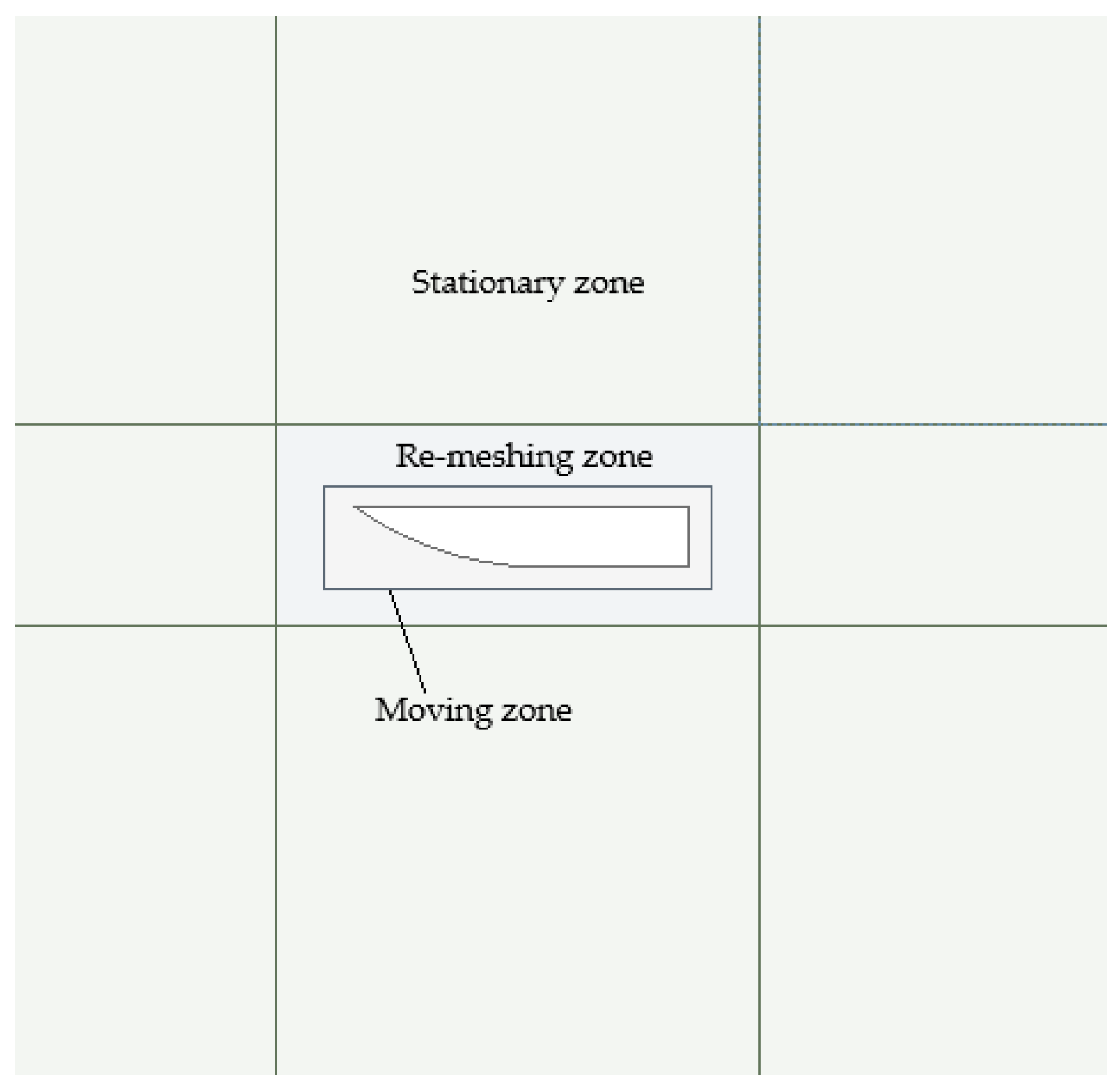
The two geometries used in this research were the 2 D hulls presented in [39,44], which are later referred to as model 1 and model 2, respectively. As the aim was to investigate the dynamic stability during take-off and landing, only the hull of the seaplane was considered in the simulations. During take-off and landing, the hydrodynamic stability prediction is of great importance in the design of seaplanes, as it provides information about the water drag resistance and porpoising [7]. As shown in Figure 3, the computational domain is divided into three zones: the moving zone, the re-meshing zone, and the stationary zone. This is because the area around the hull of the seaplane must oscillate according to the structural response of the hull to sea waves. The re-meshing zone does not oscillate; however, the mesh in this zone responds to the motion of the moving zone and constantly re-constructs the elements of the mesh. This is performed to reduce the computational time, because only the re-meshing and moving zones have a high-definition mesh.
The distance from the free surface (sea water level) to the top of the domain was assumed to be equal to the hull length. The depth of the domain was also equal to the hull length. Moreover, the distance from the centre of gravity of the hull to the outlet was assumed to be four times the length of the hull. Nevertheless, the distance from the centre of gravity (CG) of the hull to the inlet was twice the length of the hull. This agrees with the International Towing Tank Conference (ITTC)’s practical guidelines for ship CFD applications [45]. The body-fixed reference frame axes were chosen to coincide with the principal axes of inertia, and the origin was taken coincident with the centre of gravity of the hull.

3.2.2. Mesh

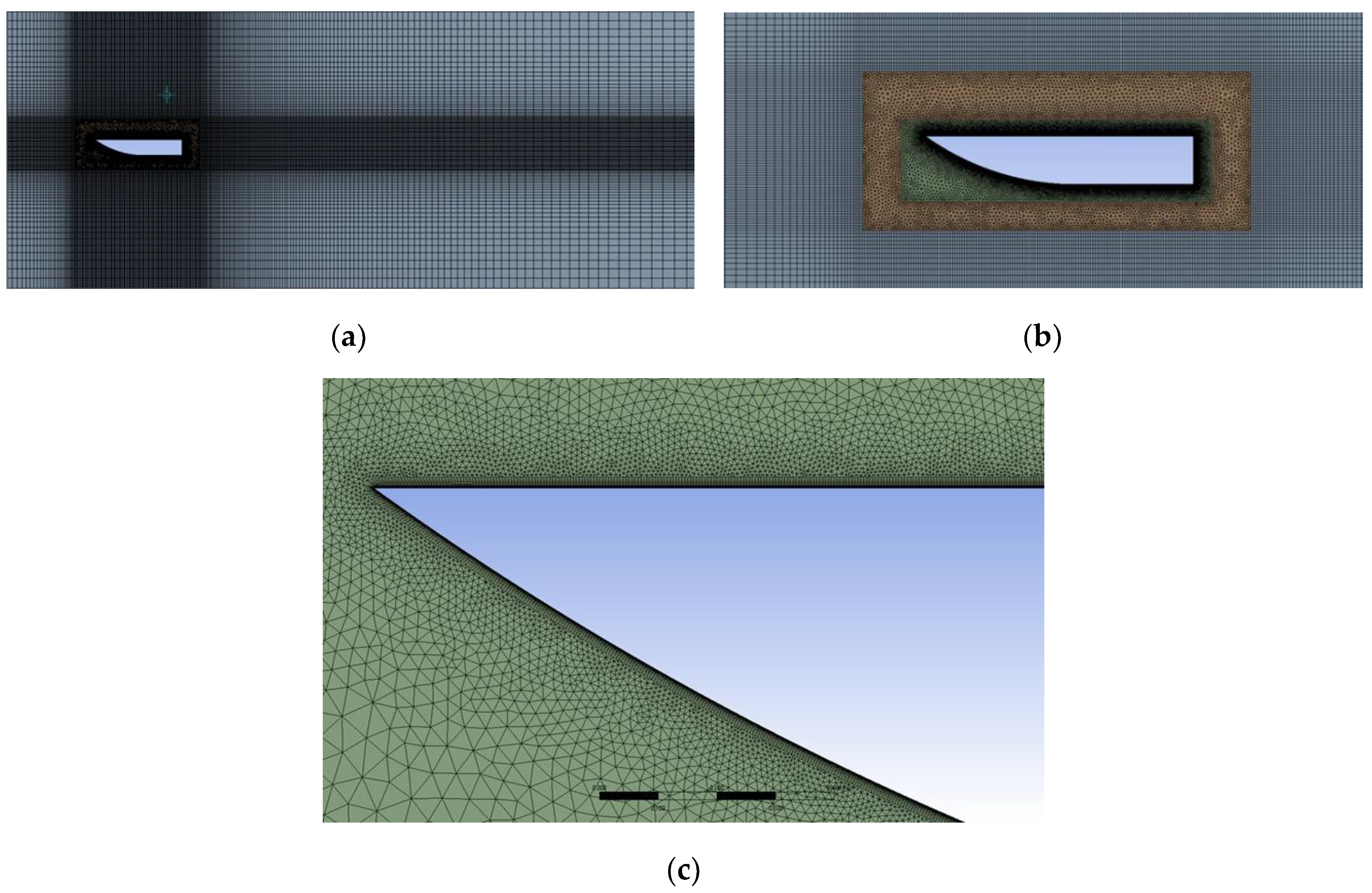
As presented in Figure 4, a hybrid mesh was generated that combined structured (hexahedral) elements in the stationary zone and unstructured (tetrahedral) elements in the re-meshing and moving zones. This was conducted to reduce the computational time. The stationary zone does not necessitate any need for a high-definition mesh, as it is just a freestream region. The mesh density was evaluated for seven different boundary-layer edge sizes and studied against the coefficient of the drag of the hull. The optimal edge size of the hull was found to be 0.0082 ft. This is the point at which the solution starts to converge, in which the difference in the coefficient of drag produced by any smaller edge size is negligible. In addition, this edge size produces approximately 165,000 mesh elements, which can be simulated using a high-specification PC within an acceptable time. In unsteady flow simulations, using an appropriate dimensionless wall distance, y + , is crucial for accurately resolving the boundary layer around the hull [46]. To ensure that y + is less than one, the boundary layer was refined by setting the first-layer height to 6 × 10 3 × L , where L is the length of the hull. This guarantees that there are at least 45 layers surrounding the boundary layer regions.

3.2.3. The Numerical Domain

The volume of fluid (VOF) method was selected in the multiphase flow tab. The computational domain was defined as a two-phase flow domain with air as the primary fluid and water as the secondary fluid. The open-channel flow and open-channel wave BC (boundary conditions) should be enabled to define the head-sea wave. The numerical beach should be enabled in the stationary zone to account for the wave damping at the outlet and reduce the computational time. This suppresses wave reflection at the outlet. A dynamic mesh was used in this investigation. This allowed the hull to respond to sea waves in the form of motions with only two degrees of freedom. The motion was restricted by the use of a user-defined function (UDF). The UDF was also used to record the heave and pitch motions and define the mass and mass moment of inertia of the hull. Smoothing and re-meshing were enabled to allow the mesh to re-construct the moving cells.

4. Results

4.1. Hydrodynamic Coefficient Calculation

The determination of the coefficients, exciting force, and moments of Equations (1) and (2) is a major problem in the analytical study of motion. To simplify this problem, the boat was divided into transverse strips or segments [47]. Then, the added mass, damping, restoring force, external excitation force, and moment coefficients were calculated using two-dimensional hydrodynamic theory [39]. This method is known as the “strip theory”. It has been widely used to calculate the hydrodynamic coefficients of ships, boats, planing hulls, and sea-craft. The objective of this theory is to predict the motion of floating bodies in the heave and pitch directions when the oscillation frequency is known [39]. Over the past century, several strip theory methods have been formulated, such as those of Korvin-Kroukovsky [44]; Salvesen, Tuck, and Faltinsen [48]; and Lewis [49]. The key differences between them are in the number of segments the hull is divided into, and in the assumptions made when calculating the sectional added mass, sectional damping, sectional restoring force, and moment coefficients.
Strip theory is a very efficient tool owing to its ability to analytically determine the coefficients in the coupled heave and pitch equations of motion under any sea wave or speed condition. This facilitates the improvement of the ship design so that the performance can be enhanced in severe weather or sea conditions. In this section, the strip theory method proposed by Bhattacharyya [39] was applied to obtain the values of the coefficients of the coupled heave and pitch equations so that further analytical investigations could be carried out. To be compatible with the objectives of this research, a few assumptions were made in the mathematical formulation of the strip theory, such as the assumptions that the sea wavs are periodic and linear (regular sea waves/sinusoidal); the forces and moments generated by the wind and propellers can be neglected; the sea-craft is unrestrained, is rigid, and has a slender shape; the sea-craft is symmetrical in the x–z plane (transverse axis); the seaplane is heading into the waves in a direction transverse to its peak line (i.e., the heading angle ( μ ) is 180°); the vertical motion is composed of coupled pitching and heaving motions only; and the wavelength is equal to the hull length.
With these assumptions in mind, the hull was divided into a few segments or strips that were rigidly connected to each other, and the flow around it was considered two-dimensional in nature. These considerations allowed the problem to be reduced from three to two dimensions, with each segment treated as part of an infinite cylinder with two-dimensional flow around it. This implies that there is no interaction between the flows at adjacent segments [39]. The response of each segment was then calculated separately, and the total response of the hull was determined by integrating the component reactions of all the segments over the total length of the planing hull. In summary, strip theory can be performed using the following steps:
  • The hull is divided into four sections to provide a representation of the underwater hull shape.
  • The sectional added mass, damping, and restoring force coefficients are then determined by considering the hull as a series of transverse segments.
  • Subsequently, the hydrodynamic coefficients of the heave and pitch equations are calculated by performing pressure integration along the length of the hull.
  • Finally, the excitation forces and moments are calculated using Newton's second law based on the given sea wave characteristics and hull shape.

4.2. Geometry and Conditions

The geometric properties of the two hull models used in this study are listed in Table 1. The centre of gravity (CG) of the hull was assumed to coincide with the centre of mass and centre of rotation. Strip theory can now be applied to determine the coefficients of the heave and pitch equations. In order to study the stability during take-offs and landings, investigations were carried out on two Froude numbers ( F n ); 0.1 and 0.2. According to Fossen [50], this is the take-off or landing regime where the hull is supported by hydrodynamic forces. This is the regime of maximum hydrodynamic resistance, where a porpoising prediction is of great importance. The Froude number ( F n ) is a non-dimensional quantity used in hydrodynamics to study the effect of gravity on fluid motion [50]. The incident wave amplitude was considered to be 0.2 ft and 0.1 ft in the simulations performed for models 1 and 2, respectively.

4.3. Discussion of Results

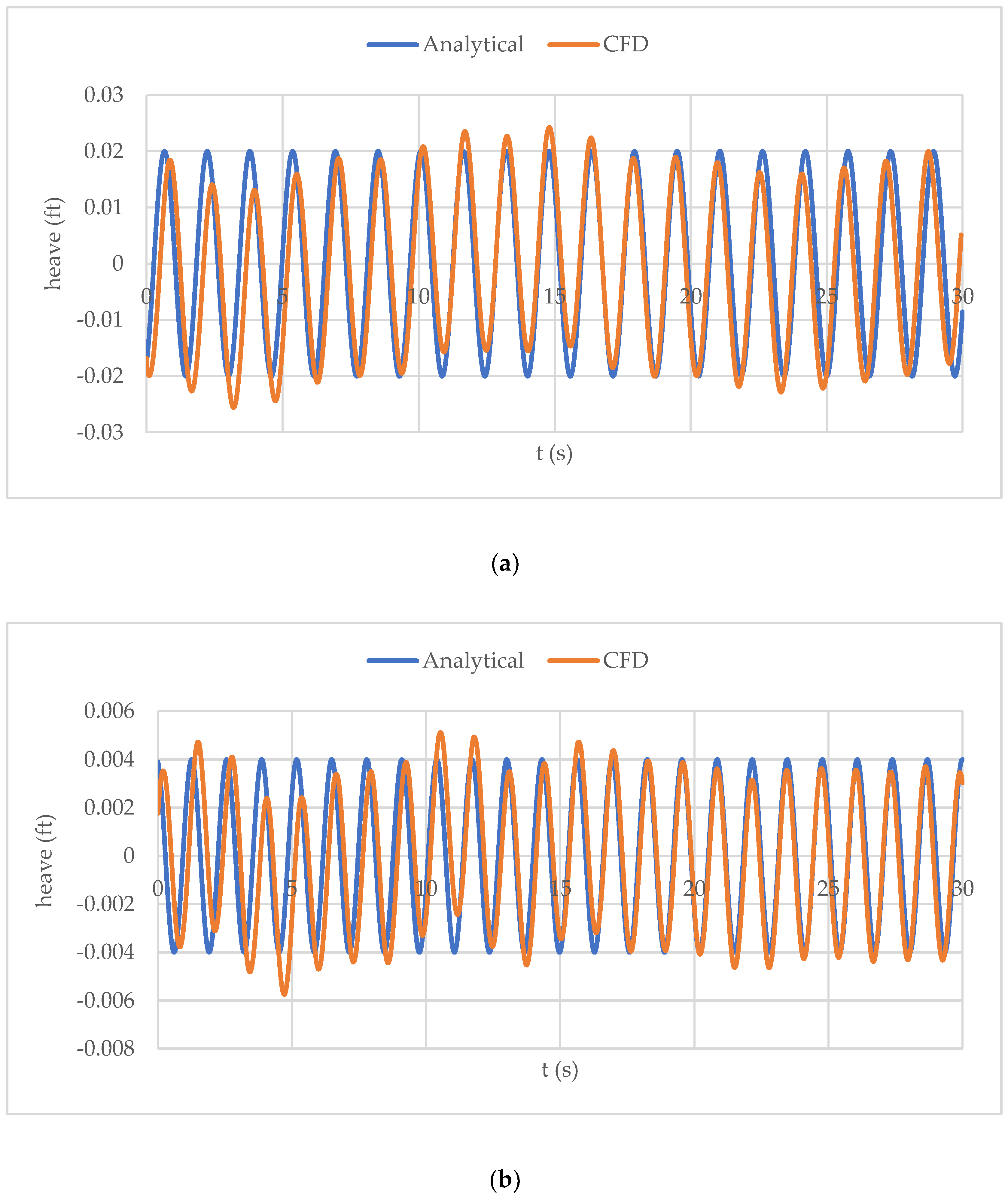
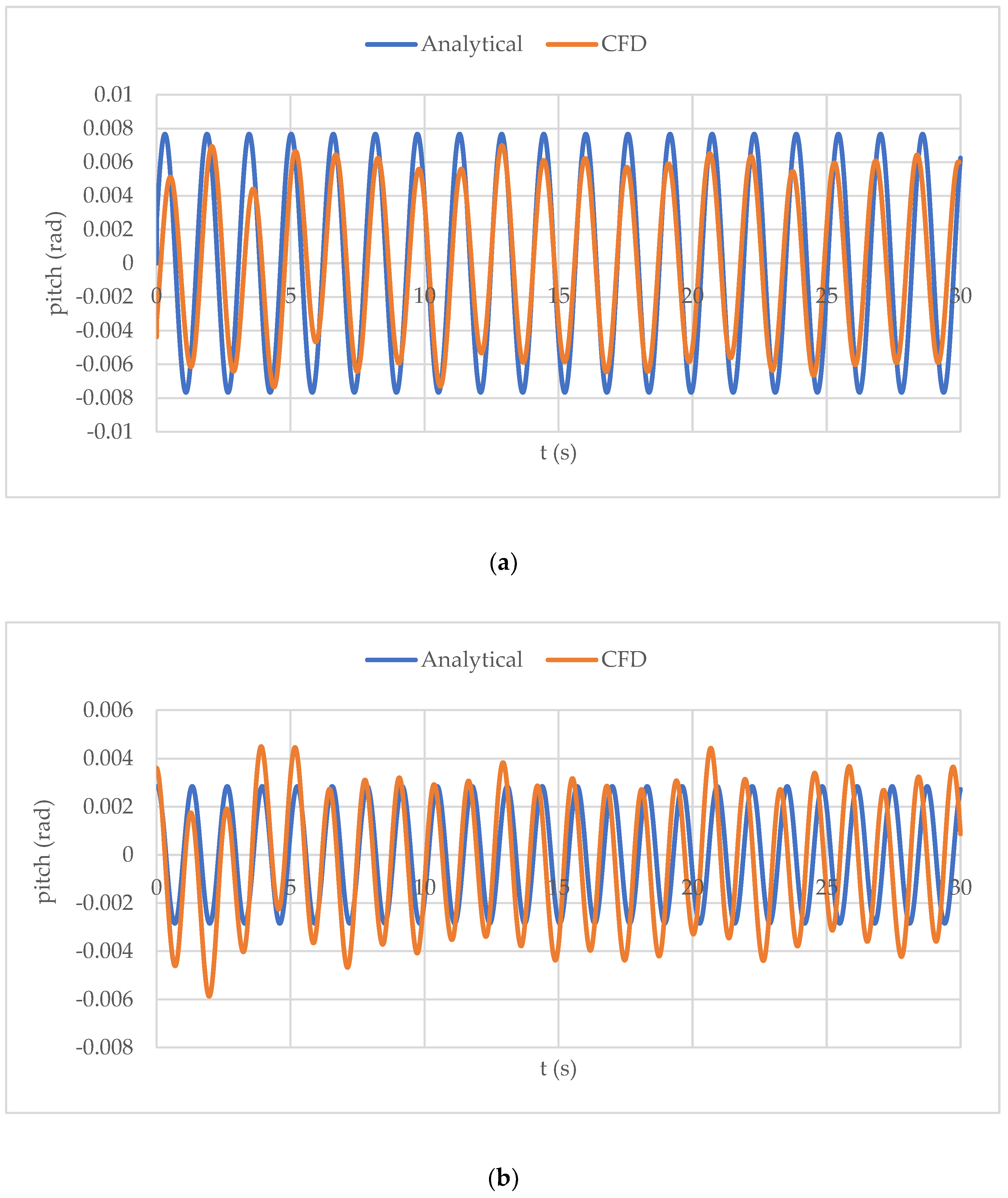
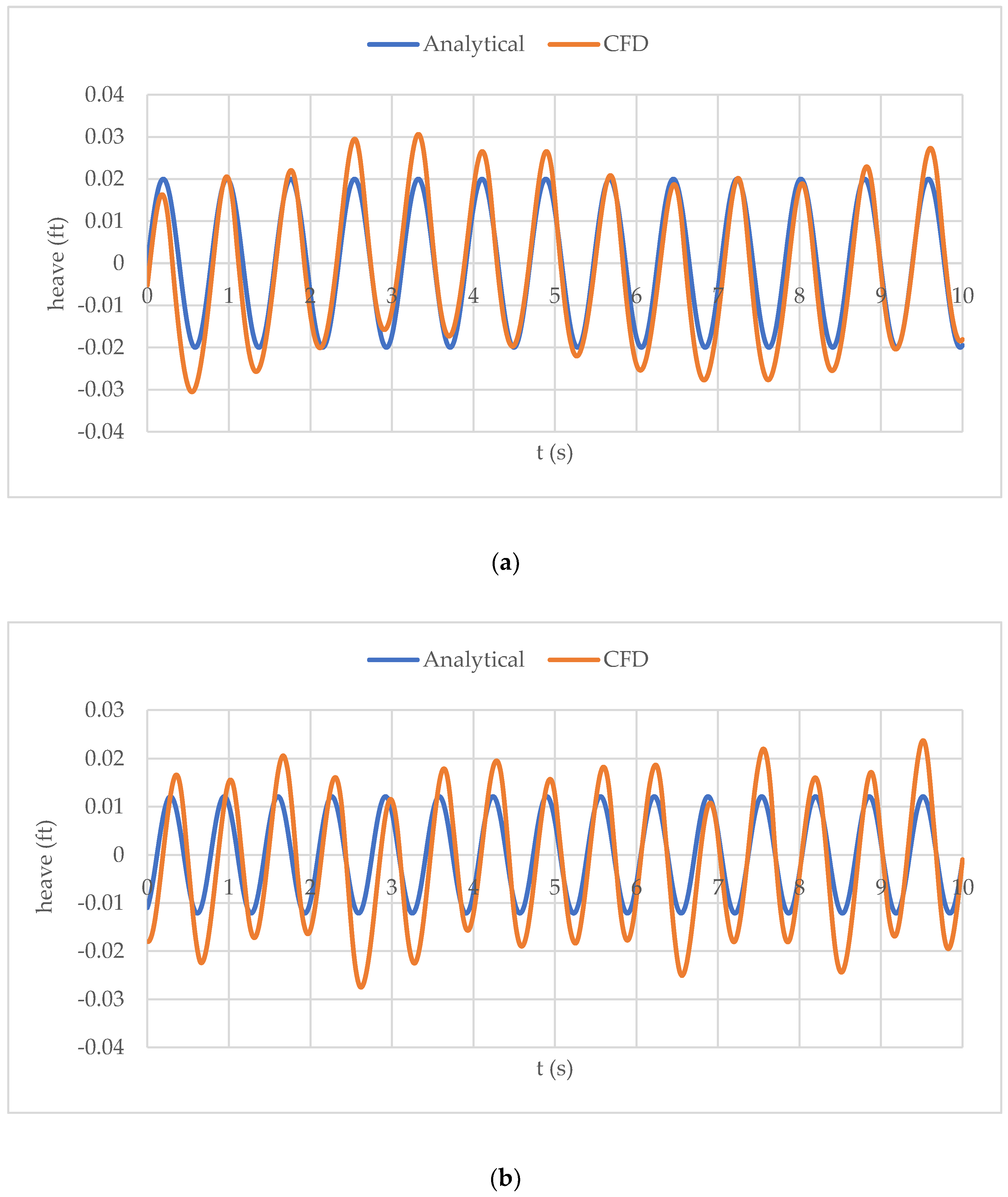
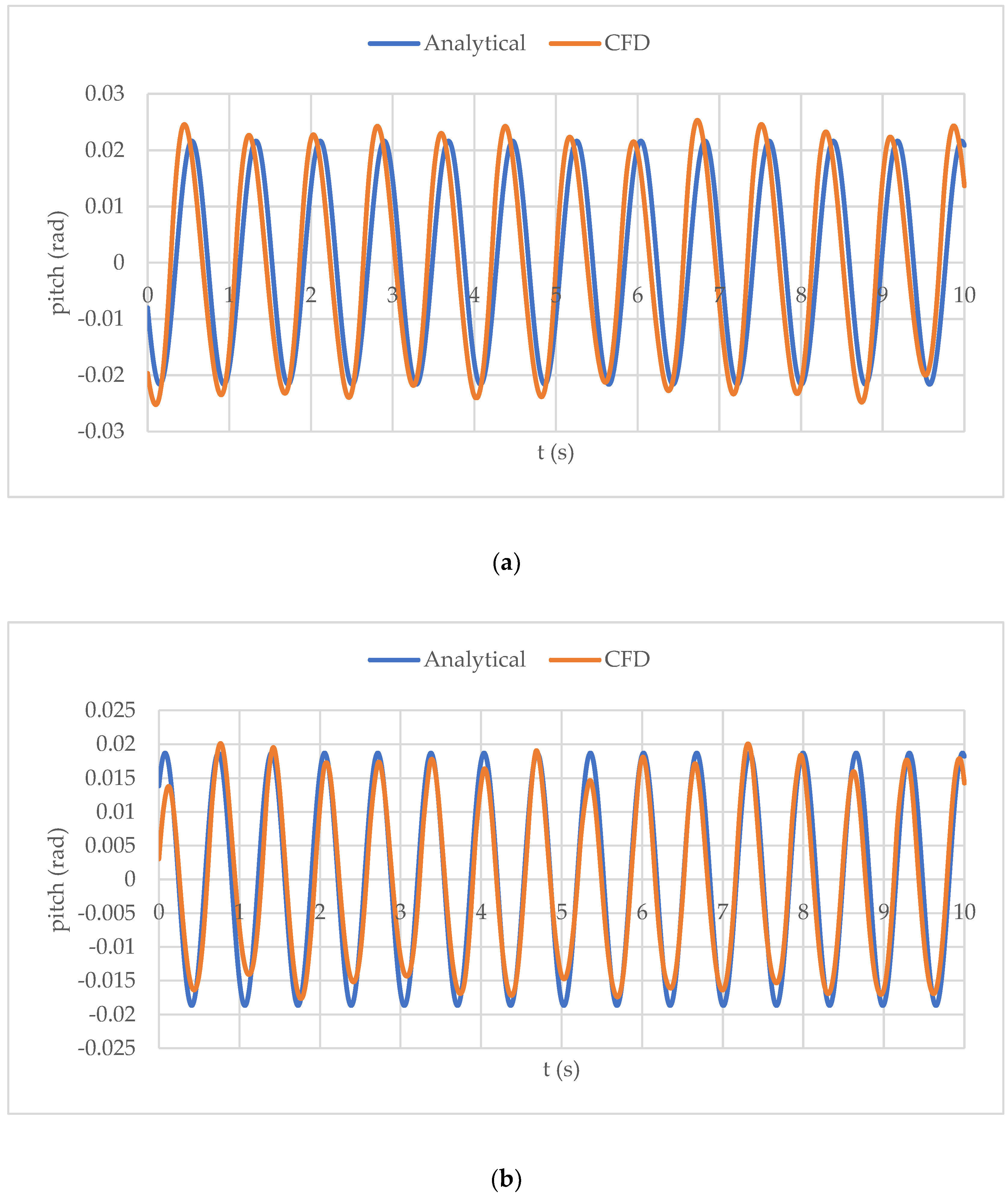
The analytical and CFD simulation results of heaving and pitching for model 1 are shown in Figure 5 and Figure 6, respectively. The CFD solution predicted the motion to oscillate with an unsteady frequency, whereas the analytical solution only produced a constant frequency of oscillations. This is because, in 2 D simulations, the water is restricted to only flow underneath the hull, whereas in reality, a significant amount of water is diverted around the sides of the hull. This leads to the motion response of the hull being greater than expected, as less energy is dissipated from the hull to the water. This is owing to the lower damping rate experienced by two-dimensional hulls compared to three-dimensional ones. This explains the high heaving amplitude of motion and the lower pitch amplitude produced in the CFD solution. The lower pitch amplitude can be explained by the fact that pitching is restricted because it is a 2 D hull, and the buoyancy force is greater when the centre of buoyancy changes in response to the increase in pitching. There is an inconsiderable discrepancy between the results of the two methods in the first 5 s of Figure 5 and Figure 6. This is because the location of the free surface was defined based on a length-to-draft ratio of 10. However, this depends on the weight, location of the CG, and speed of the hull, and it takes a few seconds to stabilise. When the Froude number F n was increased to 0.2, the motion amplitude decreased, while the oscillation frequency increased. The predicted amplitude matched the CFD results very accurately, although the pitching frequency from the CFD solution showed a slight increase over time. This can be attributed to the increased motion response of the 2 D hull, as previously mentioned.
The findings for model 2 are shown in Figure 7 and Figure 8. Owing to the significantly higher frequency of oscillations in this model compared with the previous model, the data are only displayed for 10 s . This is because of its much lower overall length and weight. The results of this model demonstrate that the heaving and pitching amplitudes obtained from both methods are in good agreement. Because the centre of buoyancy travelled a shorter distance compared to model 1, the pitching amplitudes obtained from both methods showed good agreement. In addition, because the hull in this case was much lighter, it stabilised quickly after the simulation began. As a result, the amplitude and frequency predictions were closely aligned. When the speed was increased, the results became more stable, and the oscillation frequency from the CFD solution remained nearly constant. Although the heaving amplitude from the CFD solution was slightly higher than the analytically predicted value, the pitch amplitude and frequency were well matched.

5. Conclusions

A new nonlinear prediction approach was developed to model the motion of seaplanes as they accelerate across head-sea waves. This method is based on a system of coupled, forced heaving and pitching equations of the Duffing type with cubic nonlinearities. This new nonlinear prediction method was validated using Fluent. This novel approach enables the prediction of the nonlinear dynamics of seaplanes traveling in head-sea waves. The analysis method presented in this study is not limited by geometrical characteristics or operational conditions. Based on the findings of this analytical investigation, the following conclusions can be drawn:
  • The Poincaré–Lindstedt perturbation technique has been shown to be capable of analytically solving nonlinear equations of motion that describe the motion of seaplanes.
  • The solution to the motion equations demonstrates the structural response of the hull to external excitations (waves).
  • The effects of nonlinearity and coupling on the frequency and amplitude of motion can be utilised to control porpoising.
  • Seaplane porpoising is a well-defined zone where non-sustained oscillations transitions into sustained oscillations, and it has been proven that this region may be controlled by decreasing the natural frequency of the system, which is regulated by the mass of the hull.
The following points present further areas of investigation for future research:
  • Nonlinear wave theories, such as the Cnoidal wave theory [51,52,53] and the nonlinear Stokes wave theory [54,55], could be used to study the nonlinear motion of seaplanes. In addition, irregular sea waves could be considered [56,57].
  • Nonlinearity can be incorporated into the calculation of hydrodynamic coefficients, potentially leading to nonlinear strip theory. This approach would capture the complex hydrodynamic interactions and three-dimensional effects present during real-world seaplane operations in waves.
  • This technique can be used to explore motion in three dimensions using an asymptotic approach, which enables the addition of extra degrees of freedom such as rolling. A more thorough examination of the structure's motion and behaviour can be accomplished by integrating these axes. Additionally, a Digital Twin Lab can be established using the data produced by this method, where prediction models and real-time simulations can be created.

References

  1. Yun, L.; Bliault, A.; Doo, J. WIG Craft and Ekranoplan; Springer: 2010.
  2. Rozhdestvensky, K. V. Wing-in-Ground Effect Vehicles. Prog. Aerosp. Sci. 2006, 42, 211–283. [Google Scholar] [CrossRef]
  3. He, W.; Yu, P.; Li, L. K. B. Ground Effects on the Stability of Separated Flow Around a NACA 4415 Airfoil at Low Reynolds Numbers. Aerosp. Sci. Technol. 2018, 72, 63–76. [Google Scholar] [CrossRef]
  4. Faltinsen, O. M. Hydrodynamics of High-Speed Marine Vehicles; Cambridge University Press: 2005.
  5. Duan, X.; Sun, W.; Chen, C.; Wei, M.; Yang, Y. Numerical Investigation of the Porpoising Motion of a Seaplane Planing on Water with High Speeds. Aerosp. Sci. Technol. 2019, 84, 980–994. [Google Scholar] [CrossRef]
  6. Nangia, R. K. Aerodynamic and Hydrodynamic Aspects of High-Speed Water Surface Craft. Aeronaut. J. 1987, 91, 241–268. [Google Scholar] [CrossRef]
  7. Dala, L. Dynamic Stability of a Seaplane in Takeoff. J. Aircr. 2015, 52, 964–971. [Google Scholar] [CrossRef]
  8. Jothimurugan, R.; Thamilmaran, K.; Rajasekar, S.; Sanjuán, M. A. F. Multiple Resonance and Antiresonance in Coupled Duffing Oscillators. Nonlinear Dyn. 2016, 83, 1803–1814. [Google Scholar] [CrossRef]
  9. Lenci, S. Exact Solutions for Coupled Duffing Oscillators. Mech. Syst. Signal Process. 2022, 165, 108299. [Google Scholar] [CrossRef]
  10. Guo, Y.; Ma, D.; Yang, M.; Liu, X. Numerical Analysis of the Take-Off Performance of a Seaplane in Calm Water. Appl. Sci. 2021, 11, 6442. [Google Scholar] [CrossRef]
  11. Kring, D.; Huang, Y.-F.; Sclavounos, P.; Vada, T.; Braathen, A. Nonlinear Ship Motions and Wave-Induced Loads by a Rankine Method. In Twenty-First Symposium on Naval Hydrodynamics; The National Academies Press: 1997; pp 45–63.
  12. Song, Z.; Deng, R.; Wu, T.; Duan, X.; Ren, H. Numerical Simulation of Planing Motion and Hydrodynamic Performance of a Seaplane in Calm Water and Waves. Eng. Appl. Comput. Fluid Mech. 2023, 17, 2244028. [Google Scholar] [CrossRef]
  13. Xie, H.; Wei, X.; Liu, X.; Liu, F. Analysis of Fluid Dynamic Behavior and Impact Load on Oblique Water Entry of a Two-Dimensional Seaplane Based on VOF Method. Ocean Eng. 2023, 274, 114028. [Google Scholar] [CrossRef]
  14. Tavakoli, S.; Zhang, M.; Kondratenko, A. A.; Hirdaris, S. A Review on the Hydrodynamics of Planing Hulls. Ocean Eng. 2024, 303, 117046. [Google Scholar] [CrossRef]
  15. Zhou, H.; Hu, K.; Mao, L.; Sun, M.; Cao, J. Research on Planing Motion and Stability of Amphibious Aircraft in Waves Based on Cartesian Grid Finite Difference Method. Ocean Eng. 2023, 272, 113848. [Google Scholar] [CrossRef]
  16. Wang, L.; Qin, S.; Fang, H.; Wu, D.; Huang, B.; Wu, R. Inhibition on Porpoising Instability of High-Speed Planing Vessel by Ventilated Cavity. Appl. Ocean Res. 2021, 111, 102688. [Google Scholar] [CrossRef]
  17. Zheng, Y.; Qu, Q.; Liu, P.; Wen, X.; Zhang, Z. Numerical Analysis of the Porpoising Motion of a Blended Wing Body Aircraft During Ditching. Aerosp. Sci. Technol. 2021, 119, 107131. [Google Scholar] [CrossRef]
  18. Zha, R.; Wang, K.; Sun, J.; Tu, H.; Hu, Q. Numerical Simulations of Seaplane Ditching on Calm Water and Uniform Water Current Coupled with Wind. J. Mar. Sci. Eng. 2024, 12, 296. [Google Scholar] [CrossRef]
  19. Morabito, M. G. A Review of Hydrodynamic Design Methods for Seaplanes. J. Ship Prod. Des. 2021, 37, 159–180. [Google Scholar] [CrossRef]
  20. Martin, M. Theoretical Prediction of Motions of High-Speed Planing Boats in Waves. J. Ship Res. 1978, 22, 140–169. [Google Scholar] [CrossRef]
  21. Xu, Y.; Luo, A. C. J. Series of Symmetric Period-1 Motions to Chaos in a Two-Degree-of-Freedom Van Der Pol-Duffing Oscillator. J. Vib. Test. Syst. Dyn. 2018, 2, 119–153. [Google Scholar] [CrossRef]
  22. Musielak, D. E.; Musielak, Z. E.; Benner, J. W. Chaos and Routes to Chaos in Coupled Duffing Oscillators with Multiple Degrees of Freedom. Chaos Solitons Fractals 2005, 24, 907–922. [Google Scholar] [CrossRef]
  23. Clementi, F.; Lenci, S.; Rega, G. 1:1 Internal Resonance in a Two DOF Complete System: A Comprehensive Analysis and Its Possible Exploitation for Design. Meccanica 2020, 55, 1309–1332. [Google Scholar] [CrossRef]
  24. Raj, S. P.; Rajasekar, S.; Murali, K. Coexisting Chaotic Attractors, Their Basin of Attractions, and Synchronization of Chaos in Two Coupled Duffing Oscillators. Phys. Lett. A 1999, 264, 283–288. [Google Scholar]
  25. Sunday, J. The Duffing Oscillator: Applications and Computational Simulations. Asian Res. J. Math. 2017, 2, 1–13. [Google Scholar] [CrossRef]
  26. Nayfeh, A.; Mook, D. Nonlinear Oscillations; John Wiley & Sons: 1979.
  27. Bogolubov, N.; Mitropolski, Y. Asymptotic Methods in the Theory of Nonlinear Oscillations; Hindustan Publishing Corporation: 1961.
  28. El-Naggar, A.; Ismail, G. Analytical Solution of Strongly Nonlinear Duffing Oscillators. Alex. Eng. J. 2016, 55, 1581–1585. [Google Scholar] [CrossRef]
  29. Farzaneh, Y.; Tootoonchi, A. A. Analytical Solution of Strongly Nonlinear Duffing Oscillators. Comput. Math. Appl. 2010, 59, 2887–2895. [Google Scholar] [CrossRef]
  30. He, J. Variational Iteration Method—A Kind of Non-Linear Analytical Technique: Some Examples. Int. J. Non-Linear Mech. 1999, 34, 699–708. [Google Scholar] [CrossRef]
  31. Cveticanin, L. The Approximate Solving Methods for the Cubic Duffing Equation Based on the Jacobi Elliptic Functions. Int. J. Nonlinear Sci. Numer. Simul. 2009, 10, 1491–1516. [Google Scholar] [CrossRef]
  32. He, J. H. Homotopy Perturbation Method: A New Nonlinear Analytical Technique. Appl. Math. Comput. 2003, 135, 73–79. [Google Scholar] [CrossRef]
  33. Marinca, V.; Herisanu, N. Nonlinear Dynamical Systems in Engineering: Some Approximate Approaches; Springer Science & Business Media: 2012.
  34. Nayfeh, A. H. Perturbation Methods; John Wiley & Sons: 2008.
  35. Drazin, P. G. Nonlinear Systems; Cambridge University Press: 1992.
  36. Nayfeh, A. H. Introduction to Perturbation Techniques; John Wiley & Sons: 2011.
  37. Murdock, J. A. Perturbations: Theory and Methods; SIAM: 1999.
  38. Holmes, M. H. Introduction to Perturbation Methods; Springer Science & Business Media: 2012.
  39. Bhattacharyya, R. Dynamics of Marine Vehicles; John Wiley & Sons Incorporated: 1978.
  40. Li, X.; Zhang, L.; Zhang, H.; Li, K. Singularity Analysis of Response Bifurcation for a Coupled Pitch–Roll Ship Model with Quadratic and Cubic Nonlinearity. Nonlinear Dyn. 2019, 95, 2659–2674. [Google Scholar] [CrossRef]
  41. Javanmardi, N.; Ghadimi, P. Hydroelastic Analysis of a Semi-Submerged Propeller Using Simultaneous Solution of Reynolds-Averaged Navier–Stokes Equations and Linear Elasticity Equations. Proc. Inst. Mech. Eng. M 2018, 232, 199–211. [Google Scholar] [CrossRef]
  42. Özdemir, Y. H.; Barlas, B. Numerical Study of Ship Motions and Added Resistance in Regular Incident Waves of KVLCC2 Model. Int. J. Nav. Archit. Ocean Eng. 2017, 9, 149–159. [Google Scholar] [CrossRef]
  43. Hellsten, A. Some Improvements in Menter’s k-ω SST Turbulence Model. In 29th AIAA Fluid Dynamics Conference; 1998; p 2554.
  44. Korvin-Kroukovsky, B.V. Investigation of Ship Motions in Regular Waves. In SNAME Transactions; Stevens Institute of Technology, Experimental Towing Tank, Hoboken, NJ, USA, 1955.
  45. Niklas, K.; Pruszko, H. Full-Scale CFD Simulations for the Determination of Ship Resistance as a Rational, Alternative Method to Towing Tank Experiments. Ocean Eng. 2019, 190, 106435. [Google Scholar] [CrossRef]
  46. Wang, Z.; Stern, F. Moving Air-Water Interface on No-Slip Solid Walls for High-Speed Planing Hulls. Ships Offshore Struct. 2024. [Google Scholar] [CrossRef]
  47. Masri, J.; Dala, L.; Huard, B. A Review of the Analytical Methods Used for Seaplanes’ Performance Prediction. Aircr. Eng. Aerosp. Technol. 2019, 91(6), 820–833. [Google Scholar] [CrossRef]
  48. Salvesen, N.; Tuck, E. O.; Faltinsen, O. Ship Motions and Sea Loads; 1970.
  49. Lewis, E. V. Principles of Naval Architecture, 3rd ed.; Society of Naval Architects and Marine Engineers: Jersey City, 1989. [Google Scholar]
  50. Fossen, T. I. Handbook of Marine Craft Hydrodynamics and Motion Control; John Wiley & Sons: 2011.
  51. Zhen, Y.; Chen, J. Rogue Waves on the Periodic Background in the High-Order Discrete MKdV Equation. Nonlinear Dyn. 2023, 111, 12511–12524. [Google Scholar] [CrossRef]
  52. Liu, J.; Hayatdavoodi, M.; Ertekin, R. C. A Comparative Study on Generation and Propagation of Nonlinear Waves in Shallow Waters. J. Mar. Sci. Eng. 2023, 11, 917. [Google Scholar] [CrossRef]
  53. Fu, C.; Wang, J.; Zhao, T. Analytical Calculation of Instantaneous Liquefaction of a Seabed Around Buried Pipelines Induced by Cnoidal Waves. J. Mar. Sci. Eng. 2023, 11, 1319. [Google Scholar] [CrossRef]
  54. Gao, X.; Ma, X.; Li, P.; Yuan, F.; Wu, Y.; Dong, G. Nonlinear Analytical Solution for Radiation Stress of Higher-Order Stokes Waves on a Flat Bottom. Ocean Eng. 2023, 286, 115622. [Google Scholar] [CrossRef]
  55. Pambela, A. R.; Ma, C.; Maeda, T.; Iijima, K. Stokes Wave Traveling Along a Thin Elastic Plate Floating at Water Surface. J. Fluids Struct. 2023, 120, 103919. [Google Scholar] [CrossRef]
  56. Gao, Z.; Shi, Z. Numerical Study on Damaged Ship Rolling and Capsizing in Irregular Beam Waves During Quasi-Steady Flooding. Ocean Eng. 2023, 289, 116308. [Google Scholar] [CrossRef]
  57. Krata, P.; Gil, M.; Hinz, T.; Koziol, P. A Multiparameter Simulation-Driven Analysis of Ship Response When Turning Concerning a Required Number of Irregular Wave Realizations. Ocean Eng. 2024, 302, 117701. [Google Scholar] [CrossRef]
Figure 1. Schematic of porpoising.
Preprints 138137 g001
Figure 2. Demonstration of heaving and pitching due to waves.
Preprints 138137 g002
Figure 3. The computational domain.
Preprints 138137 g003
Figure 4. The mesh created in (a) the whole domain; (b) the re-meshing and moving zones; and (c) the boundary layer region.
Preprints 138137 g004
Figure 5. Time history of heave motion for model 1 at (a) F n = 0.1 and (b) F n = 0.2 .
Preprints 138137 g005
Figure 6. Time history of pitch motion for model 1 at (a) F n = 0.1 and (b) F n = 0.2 .
Preprints 138137 g006
Figure 7. Time history of heave motion for model 2 at (a) F n = 0.1 and (b) F n = 0.2 .
Preprints 138137 g007
Figure 8. Time history of pitch motion for model 2 at (a) F n = 0.1 and (b) F n = 0.2 .
Preprints 138137 g008
Table 1. Geometrical properties of hulls.
Parameter Model 1 Model 2
Overall length (ft) 19.2 5
Beam length (ft) 2.592 0.666
Draft (ft) 1.144 0.081
Weight (lb) 2838 33.2
Radius of gyration (ft) 4.588 1.25
Moment of inertia (lb.sec².ft) 1780.2 1.611
Disclaimer/Publisher’s Note: The statements, opinions and data contained in all publications are solely those of the individual author(s) and contributor(s) and not of MDPI and/or the editor(s). MDPI and/or the editor(s) disclaim responsibility for any injury to people or property resulting from any ideas, methods, instructions or products referred to in the content.
Copyright: This open access article is published under a Creative Commons CC BY 4.0 license, which permit the free download, distribution, and reuse, provided that the author and preprint are cited in any reuse.
Prerpints.org logo

Preprints.org is a free preprint server supported by MDPI in Basel, Switzerland.

Subscribe

© 2024 MDPI (Basel, Switzerland) unless otherwise stated