1. Introduction
Flexible surgical robots are expected to become the next-generation platform for robotic surgery, offering enhanced accessibility to lesions and greater versatility to address the limitations of current rigid surgical robots [
1,
2,
3,
4,
5,
6,
7,
8,
9,
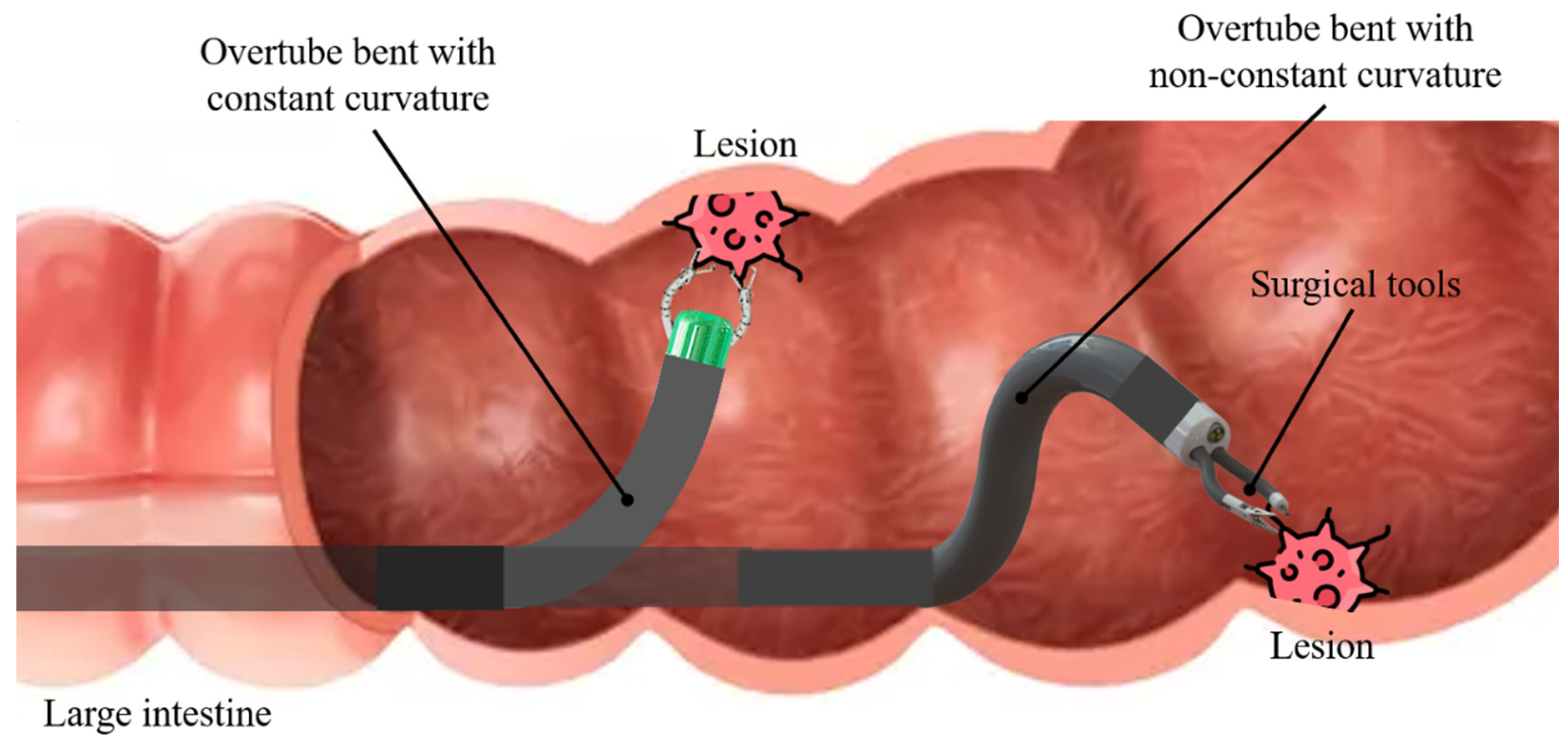
10]. Additionally, due to their flexibility and ability to navigate narrow pathways, these robots are being specifically developed for gastrointestinal surgeries (
Figure 1). Various flexible surgical robots have been proposed in preliminary studies. Flexible surgical robots can be broadly classified into two categories: semi-robotized, including ViaCatch [
1], MASTER [
2], EASE [
3], FLEX [
4], and PETH [
5], and fully-robotized, such as i2snake [
6], STRAS [
7], RAFE [
8], K-FLEX [
9], and K-COLON [
10].
To ensure flexibility and clinical safety, most flexible surgical robots are controlled using a tendon-driven mechanism. This mechanism operates the robot by using multiple tendons (or cables) that run along the length of the robot body. By pulling or releasing these tendons, the robot can bend in different directions. Considering the complexity of analyzing the dynamics and geometry of hyper-redundant manipulators with numerous joints, tendons are typically inserted parallel within the robot. For practical design, ease of control, and analysis, the main motion of the robot is commonly determined by main driving tendons inserted parallel within the robot. Control is then achieved by deriving kinematic equations based on constant curvature bending assumption [
9,
10,
11,
12,
13,
14,
15].
Flexible surgical robots can be generally divided into an overtube, which determines the approximate position within the task space, and surgical tools, which perform specific tasks such as injection, marking, cutting, and dissection. Unlike commercial endoscopes, the overtube is fixed when performing tasks to provide a stable environment and maintain an appropriate position, ensuring a clear field of view and allowing surgical tools to perform tasks efficiently [
6,
7,
8,
9,
10,
16,
17,
18,
19]. However, since tasks are generally performed in constrained and confined spaces within the human body, relying solely on the constant curvature bending of the overtube to achieve an appropriate field of view is limited. Generally, endoscopic submucosal dissection (ESD) is used as a standard treatment for early-stage gastrointestinal cancer [
20,
21,
22]. As shown in
Figure 1, the constant curvature bending of the overtube is sufficient to achieve an appropriate pose for performing tasks on some lesions in the large intestine. However, for certain lesions located in the direction of the gravity of the robot, it is necessary to bend the overtube in a specific shape, such as a cobra-like shape. To achieve the ideal pose of the overtube end tip for effective task performance within the human body, non-constant curvature bending may be required in certain situations (
Figure 1). It is common to achieve various shapes for the robot by connecting multiple segments [
9,
11,
23,
24,
25,
26]. However, this approach not only increases the difficulty of control but it is also not ideal in terms of space efficiency and cost-effectiveness. Therefore, a method is needed that enables the creation of desired shapes to the applications where the robot is used, while also ensuring a compact design, ease of use, and economic viability.
This study proposes a method for creating a desired shape by inserting an additional tendon into a hyper-redundant manipulator with rolling joints, in addition to the main driving tendons that are inserted parallel for general constant curvature bending. To the authors’ knowledge, there have been studies on reinforcing the structural stiffness of
hyper-redundant manipulator through the insertion of additional tendons [
15,
27], but no research has focused on creating a desired shape by controlling the additional tendon. The proposed method uses only two steps; Defines the path of the additional tendon and calculates the tension relationship between the additional tendons and the main driving tendons to achieve the desired shape. Tension is applied to the additional tendon and main driving tendons through the load cells to achieve the predefined desired shape.
Two major contributions have been emphasized in this paper: (1) It proposes a method that enables the hyper-redundant manipulator with rolling joints to achieve the desired shape through the insertion of additional shaping tendon; (2) The shape of the hyper-redundant manipulator can be estimated through simulation based on the principle of minimum total potential energy, using the paths of tendon insertion and the applied tensions.
The remainder of this paper is organized as follows: The Analysis of Bending Shape Based on Tendon Insertion Paths and Applied Tensions section describes a path determination method for the additional tendon. The Comprehensive Discussion section, along with the Conclusion and Further Work section, presents the discussion and conclusions of this study, as well as an outline for future research.
2. Analysis of Bending Shape Based on Tendon Insertion Paths and Applied Tensions
2.1. Mathematical Modeling
The purpose of this mathematical modeling is to analyze how the bending shape of a hyper-redundant manipulator with rolling joints changes according to the arbitrarily inserted tendons and the applied tensions.
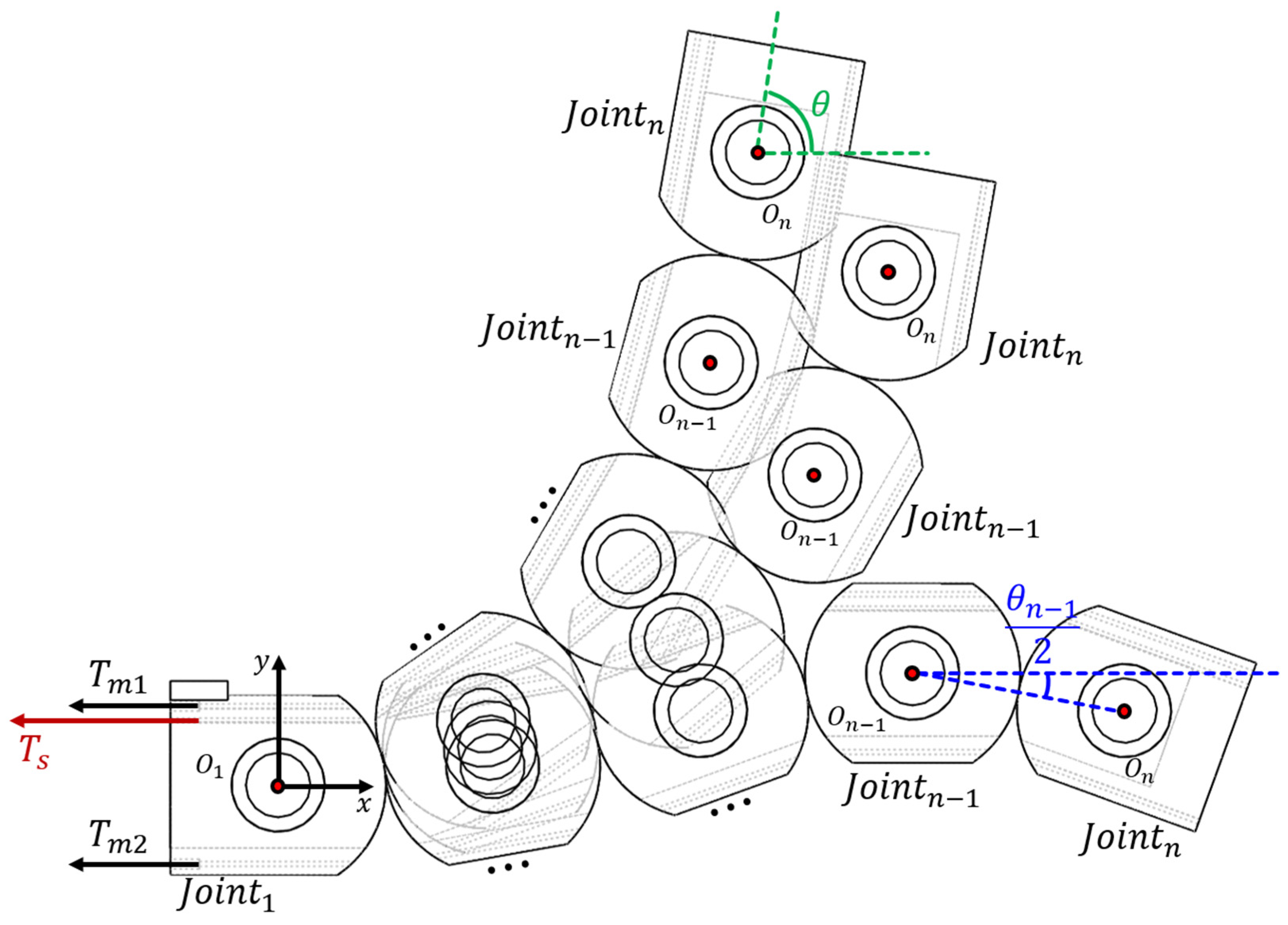
Figure 2 shows the 1-DOF overtube with
rolling joints bending due to the combined tensions applied to the inserted tendons.
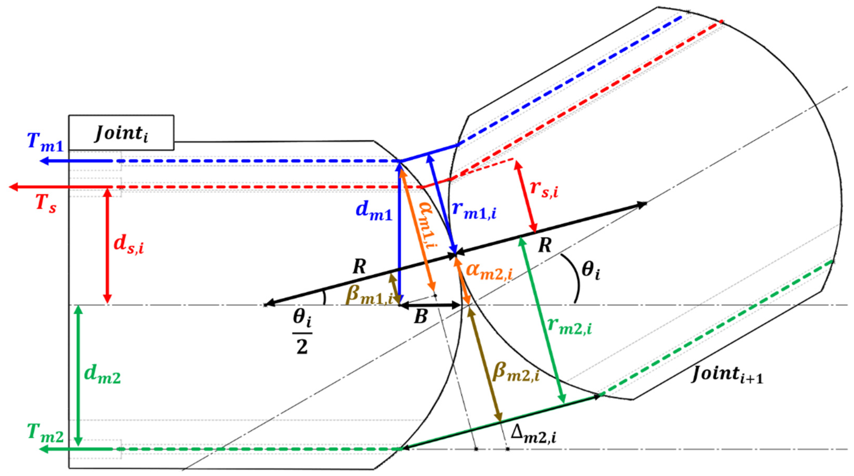
In this study, to simplify the problem definition and address practical aspects, a total of three tendons are analyzed: two main driving tendons inserted along parallel paths for constant curvature bending, and one shaping tendon inserted along an arbitrary path (
Figure 3). Each joint has rotational center denoted as
.
and
are the tensions applied
to the two main driving tendons, while
is the tension applied to the shaping tendon.
is the relative angle between
and
, and the angle of the overtube end tip after bending
can be summarized as follows:
Based on Kim’s and You’s works [
15,
27], The relationship between the tension applied to the tendons and the angles of each joint that determine the overall shape of the system was analyzed by using the minimum total potential energy principle. The
overtube will be bent in a direction that minimizes the total potential energy.
,
, and
represent the work done by the rotation of the joints due to
,
, and
, respectively, and can be defined as follows:
Here,
,
, and
are the moment arms of each tendon at between the
and
.
,
, and
are calculated as dot products for simplicity. Considering that the tension loss due to friction between the tendons and the internal holes of the joints is negligible, this study assumes that the tension applied at each joint is equal to the input tension (Eqn. (2–4)).
Figure 3 shows the moment arm of each tendon when the relative angle between
and
is
. All tendons inserted into each joint can be classified into two cases: those that assist with bending and those that resist it. The moment arm for each case can be calculated as follows:
Here,
represents the radius of rolling surface,
is the depth of the tendon hole from the top of the rolling surface, and
,
,
are the distances between each tendon and the central axis. Unlike the paths
and
of the main driving tendon for constant curvature bending, the path
of the shaping tendon, which determine various shapes, can vary for each joint. These variables can be adjusted through modifications in the mechanical design of the joint. In
Figure 3,
, which assists with bending, is similar to
in the way it is calculated and has been omitted for brevity. Finally, the
Figure 4.
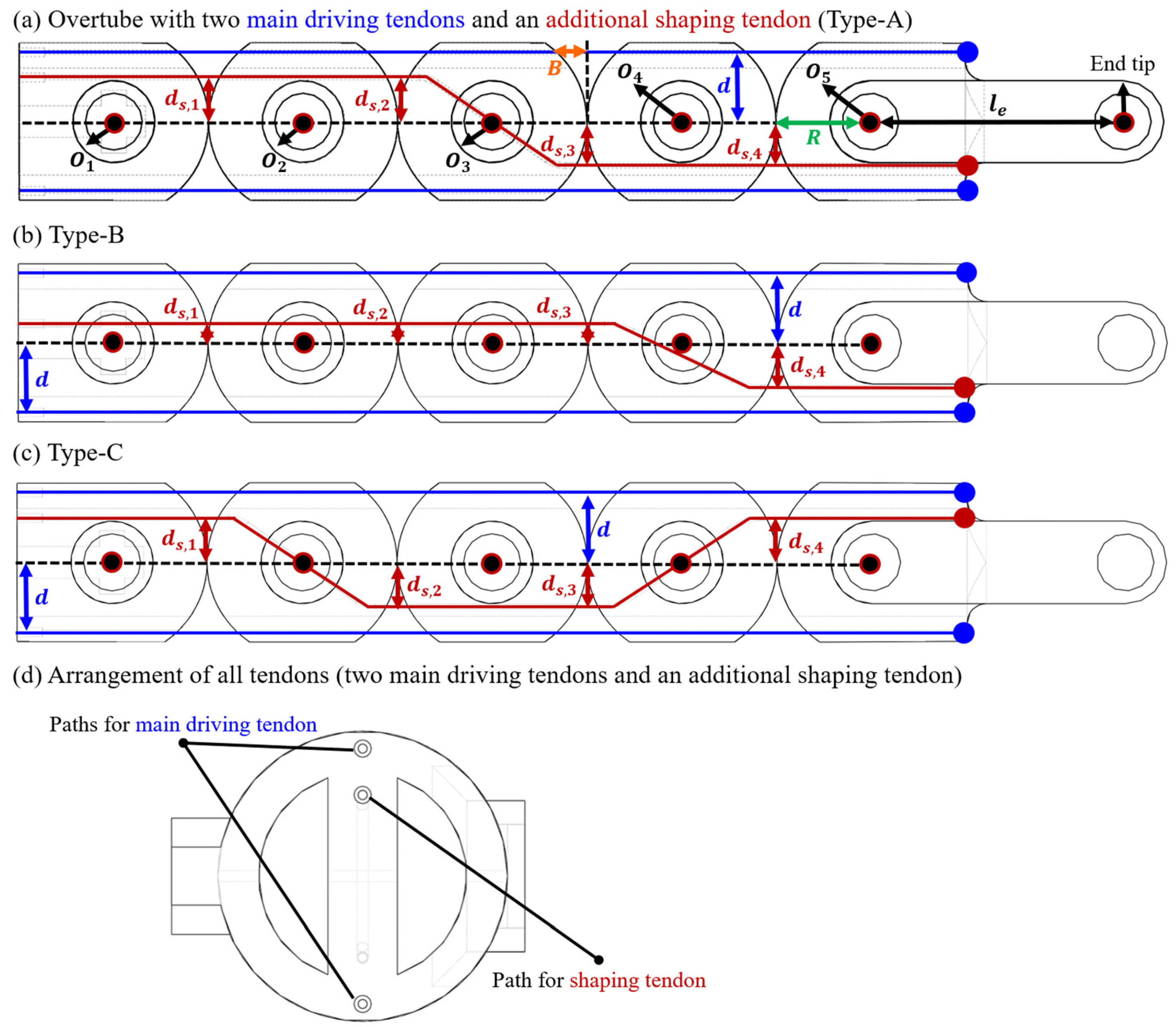
(a–c) Overall mechanical design of three different types of overtubes for analyzing the effect of the shaping tendon on the bending shape, and (d) the arrangement of all tendons.
Figure 4.
(a–c) Overall mechanical design of three different types of overtubes for analyzing the effect of the shaping tendon on the bending shape, and (d) the arrangement of all tendons.
Table 1.
The parameters that determine the tendon paths and overall shape of the joints for each type of overtube.
Table 1.
The parameters that determine the tendon paths and overall shape of the joints for each type of overtube.
| |
|
|
|
|
|
|
|
|
| Type-A |
11 mm |
7 mm |
7 mm |
-7 mm |
-7 mm |
15 mm |
4.80 mm |
40 mm |
| Type-B |
3 mm |
3 mm |
3 mm |
-7 mm |
| Type-C |
7 mm |
-7 mm |
-7 mm |
7 mm |
total potential energy
resulting from the bending of the system due to the tensions applied to the tendons can be expressed as follows:
Based on the principle of minimum total potential energy, the angle between each pair of joints that determine the bending shape of the system can be calculated using following equation:
Figure 5.
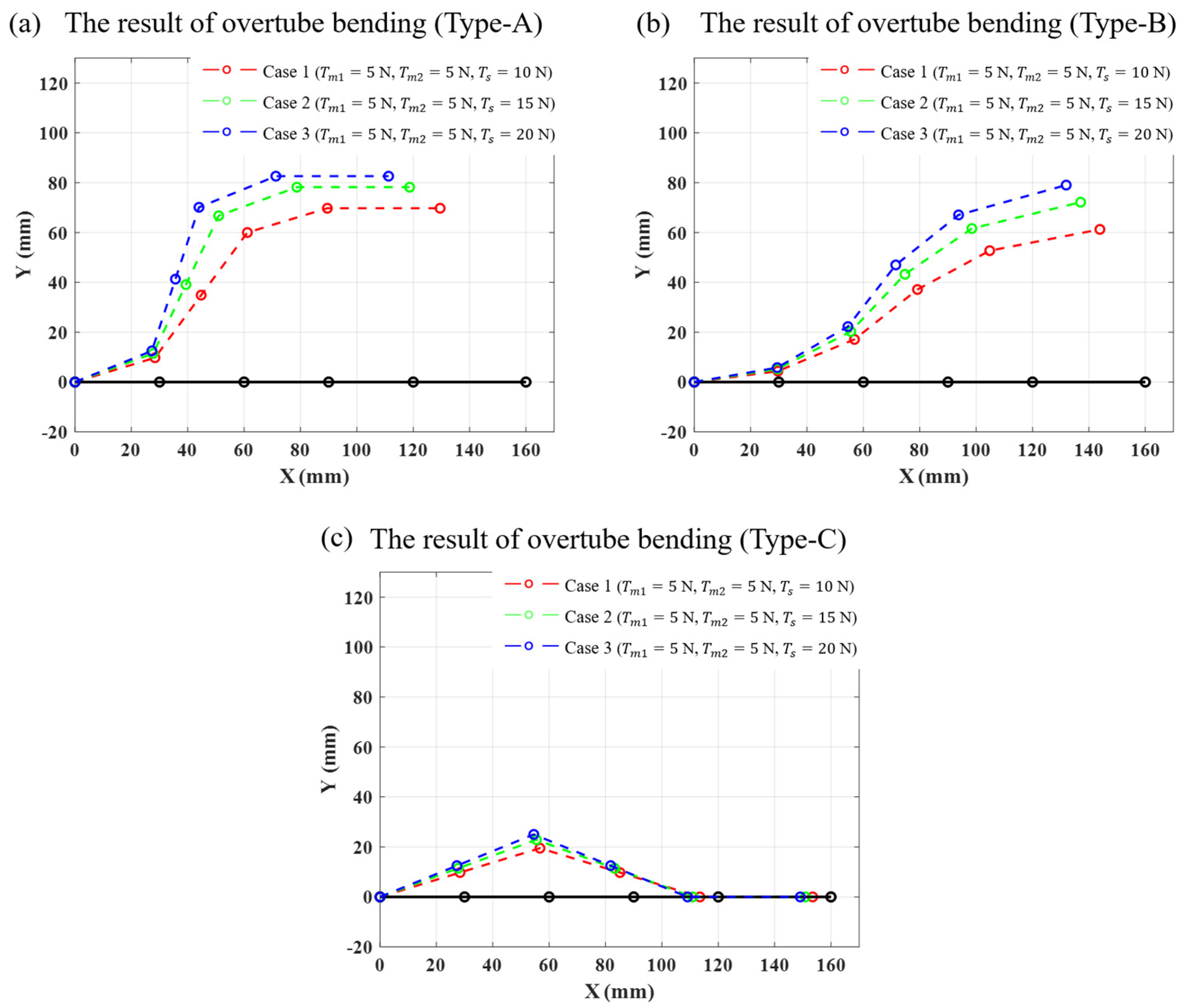
The bending results estimated based on the mathematical modeling equations proposed in Section2.1 for (a) Case 1, (b) Case 2, and (c) Case 3.
Figure 5.
The bending results estimated based on the mathematical modeling equations proposed in Section2.1 for (a) Case 1, (b) Case 2, and (c) Case 3.
The rotational centers of the joints can be determined from the angle and the forward kinematics of the overtube. Among the equations, the main strategy of the proposed method is to adjust the values , which determine the path of the shaping tendon, to achieve the desired bending shape of the overtube.
2.2. Simulation-Based Bending Shape Analysis
The primary goal of this simulation-based analysis is to identify the effect of the shaping tendon inserted within the overtube on its bending shape. Three different types of overtubes were designed in this analysis (
Figure 4). To isolate the effect of the shaping tendons, all main driving tendons were configured to follow the same path, while only the shaping tendons were designed with varying insertion paths. As described in
Section 2.1, the parameter that determines the path of the main driving tendon is
(
and
), while the parameter that determines the path of the shaping tendon is
. The parameters that determine the tendon paths and overall shape of the joints for each type of overtube are summarized in
Table 1. Among the parameters that determine the path of the shaping tendon, negative values indicate that the path is generated below the centerline. Simulations were performed for three different tension cases for each ovetube; and in all cases, the initial angle of the overtube end tip was set to 0
. The magnitude of the tension applied to each tendon in each case are as follows: (Case 1)
N,
N,
N; (Case 2)
N,
N,
N; (Case 3)
N,
N,
N.
Figure 5 shows the simulations results of the bending shape achieved by applying predefined tensions to each tendon. The angle of rotation of the overtube joints and the angle of the end tip for each case are summarized in
Table 2.
2.3. Physical Experiment Design
The primary objective of this physical experiment is to validate the effectiveness of the proposed mathematical modeling. Considering the main goal of this experiment, a comparison was made between the actual measured bending shape of the designed Type-A overtube and the estimated bending shape obtained from
Section 2.2.
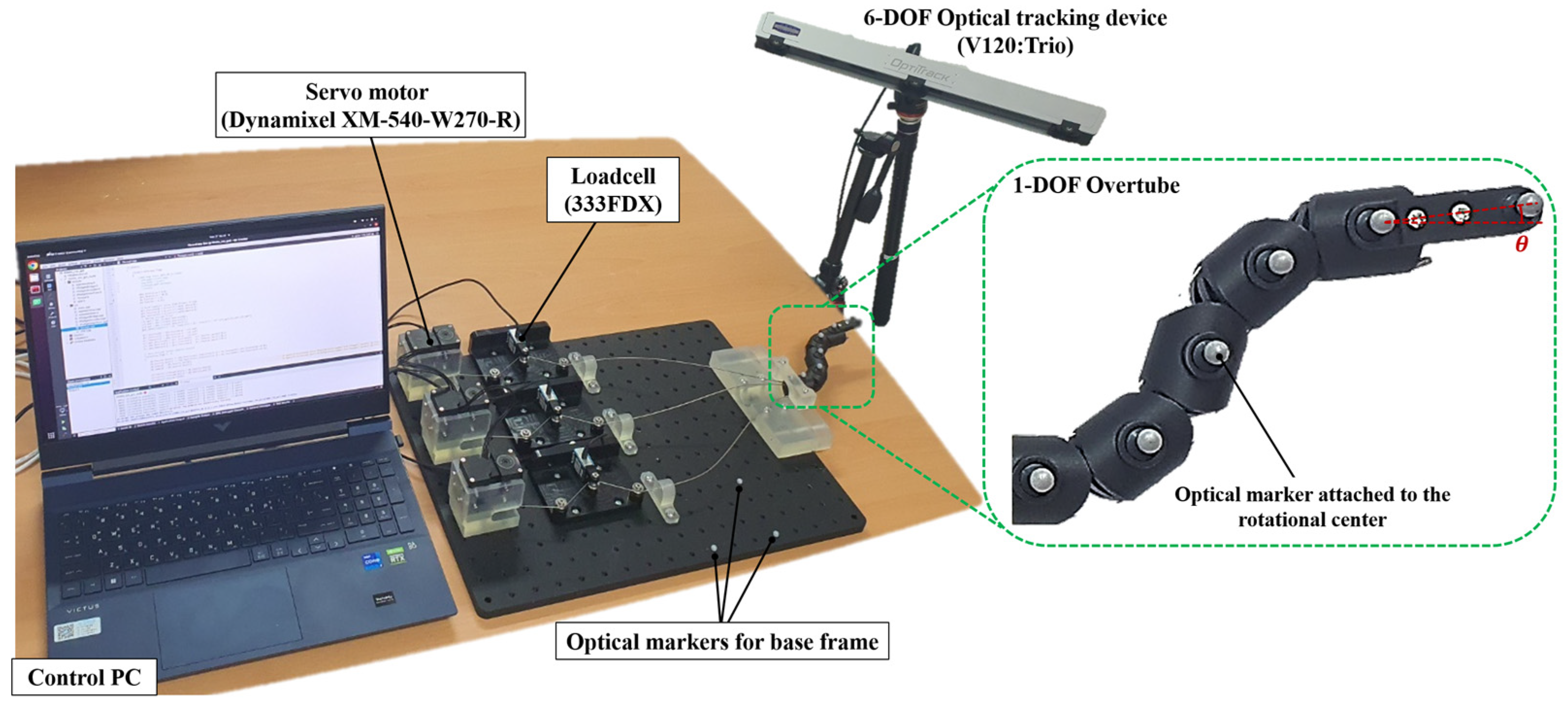
Figure 6 provides an overview of the experimental setup environment. Six optical markers were attached to the rotational centers
of each joint and to the end tip. A 6-DOF optical tracking device (V120:Trio; OptiTrack) was used to measure the overall bending shape of the overtube. Considering that the experiment aims to measure the bending shape of the overtube, the evaluation criteria were defined as the errors between the estimated and actual measured positions of the rotational centers
obtained from the mathematical modeling in
Section 2.1, as well as the errors between the estimated and actual measured angle
of the overtube end tip. The error between the estimated and actual values of each rotational center was calculated using Euclidean distance and then averaged. Considering the minimum distance that the optical tracking device can measure between markers and the precision of the 3-D printer (Form 3L, Formlabs Inc.) used to fabricate the joints, the joint parameters for the Type-A overtube were determined as follows:
mm,
mm,
mm,
mm,
mm,
mm,
mm, and
mm (
Table 1).
The physical experiments were performed in the same conditions for the three different cases outlined in
Section 2.2. Before the experiments were performed, an initial tension of approximately 3 N was applied to all tendons to maintain the initial angle of the overtube. In this study, tension control for the tendons was achieved using servo motors
Figure 7.
The actual shape of the Type-A overtube when different tensions are applied to the tendons inserted in (a) Case 1, (b) Case 2, and (c) Case 3.
Figure 7.
The actual shape of the Type-A overtube when different tensions are applied to the tendons inserted in (a) Case 1, (b) Case 2, and (c) Case 3.
(Dynamixel XM-540-W270-R; ROBOTIS), load cells (333FDX; KTOYO), and a Proportional-Integral-Derivative (PID) controller (
Figure 6).
2.4. Physical Experiment Results
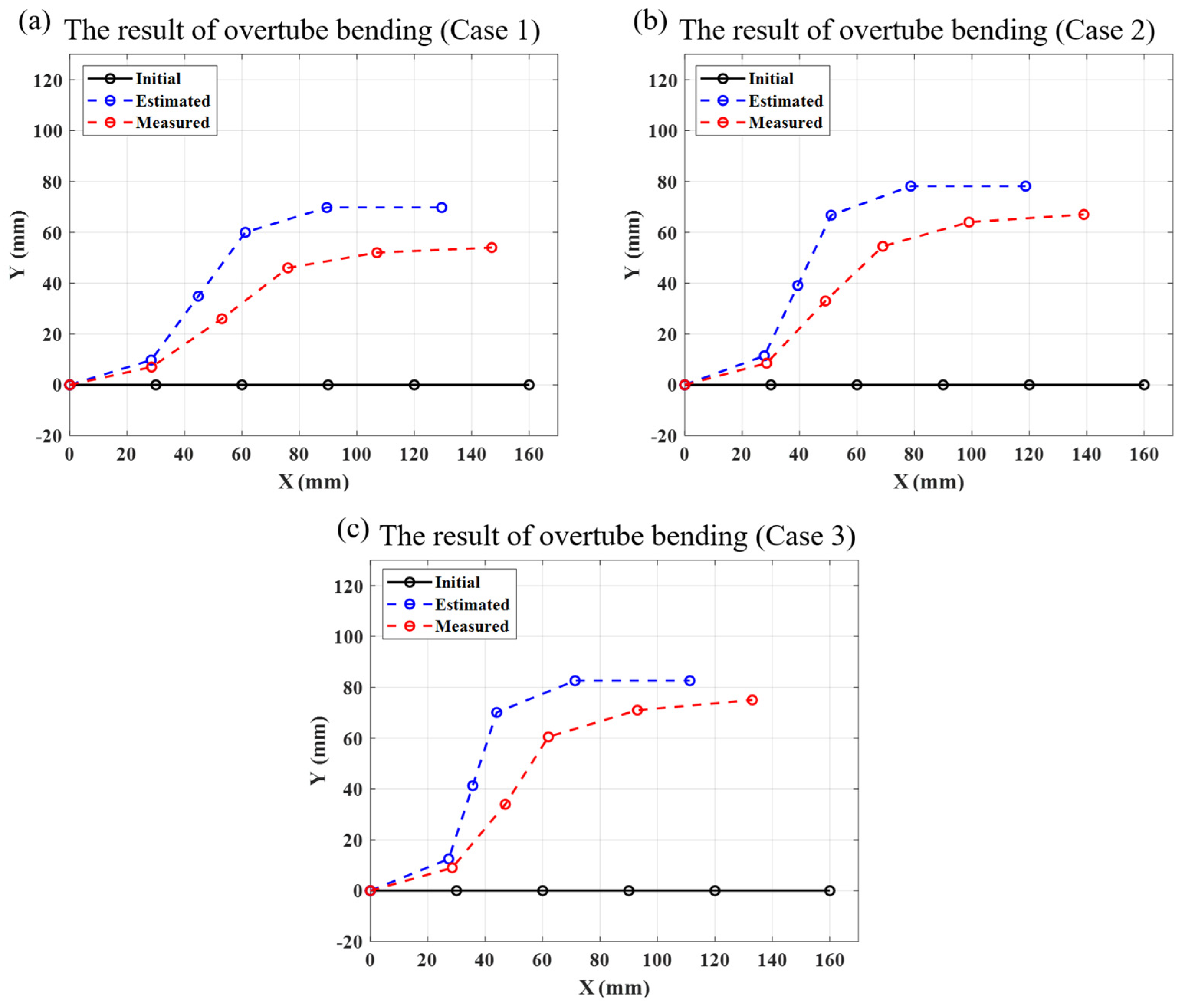
Figure 7(a–c) show the experimental results of the bending shape achieved by applying the predefined tensions to each tendon. The actual bending shape of the overtube, measured by the optical tracking device, is represented by the red dotted lines, while the bending shape estimated by the mathematical modeling equations in
Section 2.2 is shown in blue dotted lines (
Figure 8). In all cases, the initial shape of the overtube before bending is represented in black. The average error between the actual measured values and the estimated values of the positions of the rotational centers
was approximately 16.87 mm, and the end tip angle error was measured to be approximately 4.29 ° (
Table 3).
3. Comprehensive Discussion
This study proposed a conceptual method for adding a shaping tendon to determine the bending shape and also mathematically analyzed the effect of this shaping tendon, inserted along an arbitrary path in addition to the main driving tendons for constant curvature bending, on the bending shape of the overtube. The proposed method allows for achieving a specific bending shape by simply adding tendons without the need for designing additional segments. Moreover, the bending shape can be estimated based on tendon path and applied tension using the proposed mathematical modeling equations.
In
Figure 8, the overtubes represented by blue dotted lines are all estimated results based on the mathematical modeling equations from
Section 2.1. A key point to note in these equations in the relationship between the parameters that determine the tendon
Figure 8.
The actual shape of the Type-A overtube when different tensions are applied to the tendons inserted in (a) Case 1, (b) Case 2, and (c) Case 3.
Figure 8.
The actual shape of the Type-A overtube when different tensions are applied to the tendons inserted in (a) Case 1, (b) Case 2, and (c) Case 3.
Table 3.
Quantitative comparison of errors between estimated and measured rotational centers and end tip angle of the Type-A overtube.
Table 3.
Quantitative comparison of errors between estimated and measured rotational centers and end tip angle of the Type-A overtube.
| |
|
|
|
|
End tip |
|
| Case 1 |
2.75 mm |
12.10 mm |
20.39 mm |
24.89 mm |
23.51 mm |
2.86 ° |
| Case 2 |
3.03 mm |
11.40 mm |
21.78 mm |
24.74 mm |
23.15 mm |
4.29 ° |
| Case 3 |
3.70 mm |
13.51 mm |
20.41 mm |
24.63 mm |
23.02 mm |
5.71 ° |
| Average |
3.16 mm |
12.34 mm |
20.86 mm |
24.75 mm |
23.23 mm |
4.29 ° |
path (
,
, and
) and the rotation angles
of each joint (
Table 2). In examining Equations (2–4), assuming that the tension applied to the tendons remains constant, the factor that affects the work done by the rotation of the joints is the moment arm value of the tendons at each joint. The moment arm values of the tendons at each joint are determined by the design parameters of the joints (Eq. (5) and (6)). To effectively change the moment arm values without changing the overall shape of the joint, the parameters representing the tendon path are the main factors (
,
, and
). Note that, although it is omitted in
Section 2.1,
. In other words, since the angle of rotation for each joint varies with changes in the tendon path, inserting the shaping tendon along different paths enables the overtube to achieve a variety of bending shapes. In particular, in the simulation results of
Section 2.2, it is important to focus on the relations between the angles of rotation of the joints and the path of the shaping tendon, rather than the absolute value of the rotation angles. To focus exclusively on analyzing the effect of the shaping tendon, the initial angle of the overtube was set to 0°, and the same tension was applied to the two main driving tendons. Therefore, the results summarized in
Table 2 are dominated by the parameter
, which represents the path of the shaping tendon. In conclusion, the simulation results summarized in
Table 2 indicate that the amount of rotation of each joint is closely related to the ratio of moment arm lengths, which corresponds to the path of the shaping tendon. Therefore, after defining the desired bending shape of the continuum manipulator in terms of the rotation angle ratios of each joint, it is advisable for this ratio to be considered in the moment arm lengths of the shaping tendon when designing the tendon paths in the joints.
The system, consisting of rolling joints and tendons, was analyzed from an energy perspective. The work done by the rotation of each rolling joint under the tension applied to the tendon was defined, and the angles of rotation were estimated based on the principle of minimum total potential energy. The results estimated by the mathematical modeling equations were similar in behavior to those obtained from the actual physical experiments; however, errors still remained (
Figure 8 and
Table 3). The potential causes of these errors include tendon elongation, sensing errors of the load cell, and the precision of the mechanical design. In particular, there was an issue with the uneven rolling surfaces of the joints printed with a 3D printer, and it was also difficult to create paths within the joints that would ideally allow the tendon to move with appropriate tolerances. More accurate experimental results are expected if joints manufactured through metal processing are used. Additionally, this study did not consider the tension loss caused by friction between the tendon and the holes in the joints; however, it is expected that more accurate estimation results could be obtained if the tension loss occurring at each joint can be accurately modeled in the future.
In this study, a prototype overtube with an outer diameter 25 mm and a total length of 160 mm was used to primarily verify validity of the proposed method. However, for the proposed method to be applied in practical gastrointestinal surgeries, a detailed mechanical design guideline that considers the geometric characteristics of commercial endoscopes (such as outer diameter, total length, maximum bending angle, and bending curvature radius) is necessary. It is expected that more meaningful results can be achieved if design guidelines that incorporate the proposed method and address clinical considerations (based on literature reviews in the medical research field and suggestions from clinicians) are proposed.
4. Conclusions and Further Work
This study proposed method that adding a shaping tendon inserted along an arbitrary path in addition to the main driving tendons for constant curvature bending could affect the bending shape of the overtube and provided a mathematical analysis of this effect. Additionally, it was identified that the design parameters determining the tendon path are significant elements in defining the bending shape of the overtube.
In future work, research will focus on incorporating the proposed method and developing design guidelines that satisfy clinical requirements, based on consultations with clinicians and literature reviews of medical research. Additionally, the clinical effectiveness of the proposed method will be validated through ex-vivo tests in constrained spaces, such as the gastrointestinal tract.
Data Availability Statement
The original contributions presented in this study are included in the article. Further inquiries can be directed to the corresponding author.
Acknowledgments
This work was supported by 2024 Research Fund of Myongji University.
References
- D. J. Abbott., et al. Design of an endoluminal NOTES robotic system. Paper presented at: Intelligent Robots and Systems, 2007. IROS 2007. IEEE/RSJ International Conference on 2007.
- D. Lomanto., et al. Flexible endoscopic robot. Minimally Invasive Therapy & Allied Technologies 2015;24(1):37-44.
- P. W. Y. Chiu, K. Y. Ho, and S. J. Phee. Colonic endoscopic submucosal dissection using a novel robotic system (with video). Gastrointestinal Endoscopy 2021;93(5):1172-1177. [CrossRef]
- D. T. Friedrich., et al. Potential advantages of a single-port, operator-controlled flexible endoscope system for transoral surgery of the larynx. Annals of Otology, Rhinology & Laryngology 2015;124(8):665-662. [CrossRef]
- M. Hwang., et al. Evaluation of a robotic arm-assisted endoscope to facilitate endoscopic submucosal dissection (with video). Gastrointestinal Endoscopy 2020;91(3):699-706.
- P. Berthet-Rayne., et al. The i2snake robotic platform for endoscopic surgery. Annals of biomedical engineering 2018; 46(10):1663-1675.
- F. Nageotte., et al. STRAS: A Modular and Flexible Telemanipulated Robotic Device for Intraluminal Surgery. In Handbook of Robotic and Image-Guided Surgery 2020;123-146.
- R. Nakadate., et al. Surgical Robot for Intraluminal Access: An Ex Vivo Feasibility Study. Cyborg and Bionic Systems 2020. [CrossRef]
- M. Hwang, and D. S. kwon. K-FLEX: a flexible robotic platform for scar-free endoscopic surgery. The International Journal of Medical Robotics and Computer Assisted Surgery 2020;16(2):e2078.
- H. Kim., et al. Endoscopic surgery robot that facilitates insertion of the curved colon and ensures positional stability against external forces: K-COLON. The International Journal of Medical Robotics and Computer Assisted Surgery 2023;19(3):e2493. [CrossRef]
- J. Park., et al. Hysteresis Compensation of Flexible Continuum Manipulator Using RGBD Sensing and Temporal Convolutional Network. IEEE Robotics and Automation Letters 2024;9(7):6091-6098. [CrossRef]
- D. G. Lee., et al. Learning-based discrete hysteresis classifier using wire tension and compensator for flexible endoscopic surgery robots. International Journal of Precision Engineering and Manufacturing 2023;21(1):83-94. [CrossRef]
- D. Baek., et al. Hysteresis compensator with learning-based hybrid joint angle estimation for flexible surgery robots. IEEE Robotics and Automation Letters 2020;5(4):6837-6844. [CrossRef]
- M. Cho., et al. Tension Maintenance Mechanism for Control Consistency of Twisted String Actuation-Based Hyper-Redundant Manipulator. IEEE Robotics and Automation Letters 2024. [CrossRef]
- H. Kim., et al. Sigmoidal auxiliary tendon-driven mechanism for reinforcing structural stiffness of hyper-redundant manipulator for endoscopic surgery. Soft Robotics 2023;10(2):234-245. [CrossRef]
- B. Oh.,. et al. Ultra-soft and highly stretchable tissue-adhesive hydrogel based multifunctional implantable sensor for monitoring of overactive bladder. Biosensors and Bioelectronics 2023;225:115060.
- J. Kim., et al. Effects of flexible surgery robot on endoscopic procedure: Preliminary bench-top user test. 28th IEEE International Conference on Robot and Human Interactive Communication 2019;1-6.
- J. Kim., et al. Ex-vivo suturing trial with a 5-DoF robot arm for flexible endoscopic surgery robot. The 15th Asian Conference on Computer Aided Surgery 2019.
- M. Hwang., et al. A flexible endoscopic surgery robot K-FLEX and its feasibility validation in in-vivo animal trial. The 14th Asian Conference on Computer Aided Surgery 2018.
- F. Bray., et al. Global cancer statistics 2018: GLOBOCAN estimates of incidence and mortality worldwide for 36 cancers in 185 countries. CA: a cancer journal for clinicians 2018;68(6):394-424. [CrossRef]
- C. Hamashima., et al. Mortality reduction from gastric cancer by endoscopic and radiographic screening. Cancer science 2015;106(12):1744-1749. [CrossRef]
- T. Oyama., et al. Endoscopic submucosal dissection of early esophageal cancer. Clinical Gastroenterology and Hepatology 2005;3(7):S67-S70. [CrossRef]
- I. Walker. Robot strings: long, thin continuum robots. IEEE Aerospace Conference 2013; 1-12.
- S. Bayani., et al. Design of hyper redundant robot using ball screw mechanism approach. IEEE International Conference on Advanced Intelligent Mechatronics 2015; 1271-1276.
- S. Jin., et al. Kinematic model and real-time path generator for a wire-driven surgical robot arm with articulated joint structure. Applied Sciences 2019;9(9):4114. [CrossRef]
- J. Park., et al. SAM: Semi-Active Mechanism for Extensible Continuum Manipulator and Real-time Hysteresis Compensation Control Algorithm. arXiv preprint 2024; arXiv:2406.18388.
- J. M. You., et al. Design and analysis of high-stiffness hyperredundant manipulator with sigma-shaped wire path and rolling joints. IEEE Robotics and Automation Letters 2021;6(4):7357-7364. [CrossRef]
|
Disclaimer/Publisher’s Note: The statements, opinions and data contained in all publications are solely those of the individual author(s) and contributor(s) and not of MDPI and/or the editor(s). MDPI and/or the editor(s) disclaim responsibility for any injury to people or property resulting from any ideas, methods, instructions or products referred to in the content. |
© 2024 by the author. Licensee MDPI, Basel, Switzerland. This article is an open access article distributed under the terms and conditions of the Creative Commons Attribution (CC BY) license (https://creativecommons.org/licenses/by/4.0/).
