1. Introduction
Steam turbines are fluid flow machines that move generators in the power industry [
1]. Worldwide, more than 50% of the electrical energy is generated by steam turbines. Even with the rise of alternative energies, steam turbines have continued to be an essential source of electrical generation.
To obtain satisfactory overall performance, this type of turbine requires a significant pressure difference between the inlet and outlet sections to produce the steam expansion in different stages. Several years ago, at the beginning of the steam turbine development, their efficiency was 45% to 56%. Modern high-tech software and innovative materials have helped increase it, ranging from 72% to 78% [
2]. However, the constant loss of working fluid among different turbine components has been the main obstacle to achieving its highest efficiency.
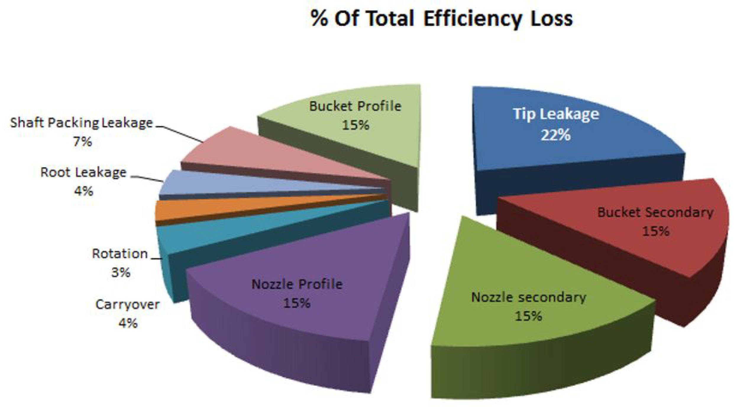
Figure 1 shows the distribution of typical efficiency loss in one steam turbine stage.
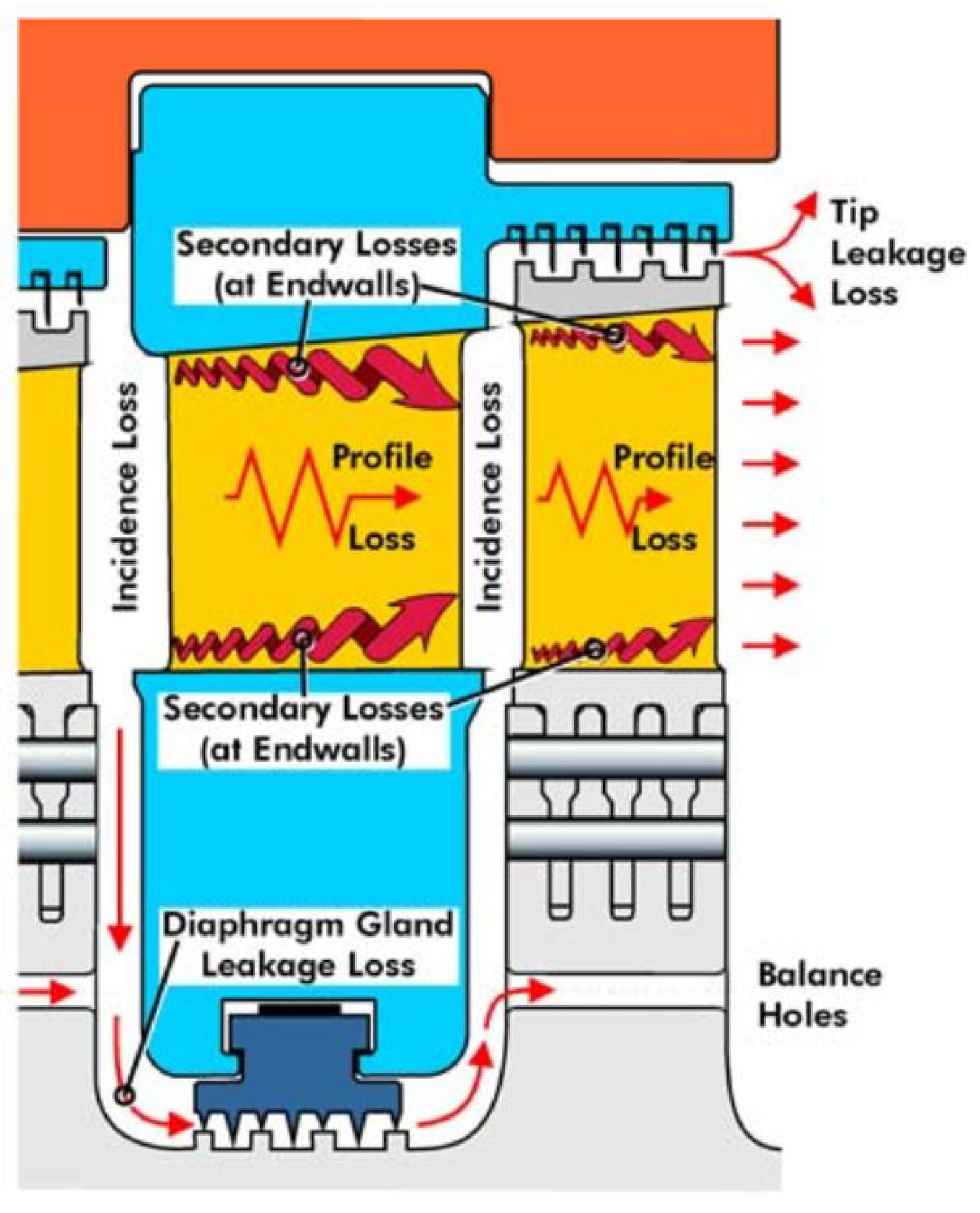
Of the leaking losses, the most significant one comes from the tip leakage (22%) due to a small gap designed to pass the fluid at the upper end of the moving blades of the expansion stage.
Figure 2 shows schematically the tip leakage loss in the expansion stage when the steam volume enters the turbine.
To avoid the efficiency loss at the tip leakage stage, a sealing system that works according to the principle of the pressure ratio has been implemented. As the fluid passes through the geometries of the seals, it fills the cavities, forming swirls inside them, causing a decrease in the leakage velocity. Thus, the pressure energy is converted into eddies and heat energy [
5].
Different companies have replaced the seal design of conventional labyrinths with more advanced turbomachinery sealing technology, reducing leakage losses [
4]. Nonetheless, the straight labyrinth seals are the most common in sealing systems that seek to maximize steam choking at the turbine blade tip. This is because they are easy to manufacture, inexpensive, and simple in their arrangement, offering a possibility for obstructing flow from a high to a low-pressure region and functioning as replacement parts in the maintenance of the steam turbines [
6]. Some investigations have proposed various staggering designs for seal chambers achieving better performance in the sealing system but with complex geometries [
7]. Other authors like Dogu et al. [
8] have presented stylized shapes at the tip of the seals or an intermediate extraction in the steam circulation system, which would diagnose its state [
1]. However, the limitation of the current commercial technology to manufacture this type of piece has always been a common factor. Darshan et al. [
9] noticed that a crush in the seal increases its efficiency after a significant maintenance procedure on a 25 MW turbine in Mexico, the observed modification could have transformed the sealing element into the ideal geometry to increase dissipation and operate closer the maximum efficiency point.
The seal system studied in this research is part of a steam turbine installed in two of the five geothermal fields in Mexico and used under commercial operation [
10]. Similarly, the turbine seal system presented a slight forward deformation, improving the performance. This study assumes that this kind of deformation modified the flow trajectory, creating vortices in the cavities of the chambers. These vorticities, in turn, should have provoked a blockage in the clearances, increasing the pressure ratio. Thus, this work investigates whether a geometrically suitable steam seal profile can modify the fluid flow trajectory along the chamber cavities. However, the number and combination of the design parameters of the seal geometry could turn into a non-smooth optimization problem, which yields an unpractical process to determine the optimal shape. Recent research has introduced new tools based on Computational Fluid Dynamics (CFD) and optimization algorithms to evaluate the performance of hydraulic structures and machinery. Among them, Herrera et al. [
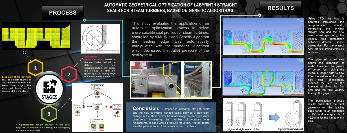
11] showed that coupling optimization and CFD algorithms systematically improved the geometric design of a turbomachinery component due to the flow information obtained from CFD predictions. However, some researchers have reported procedures to maximize the labyrinth seal performance by modifying its shape. Thus, taking this same principle, an automatic process was designed to find the geometric profile in response to the flow behavior in a research space limited by geometric restrictions. This paper proposed parameterizing the geometry for straight seals commonly used in steam turbines. The original seals were manipulated by an optimization algorithm coupled with CFD and Computer Aided Design (CAD) software, looking for the ideal shape. The present analysis proposes that the new seal geometry, with a sharp leading edge, will modify the behavior of the steam to reach the maximum static pressure difference.
2. Materials and Methods
2.1. Domain of the Labyrinth Seal
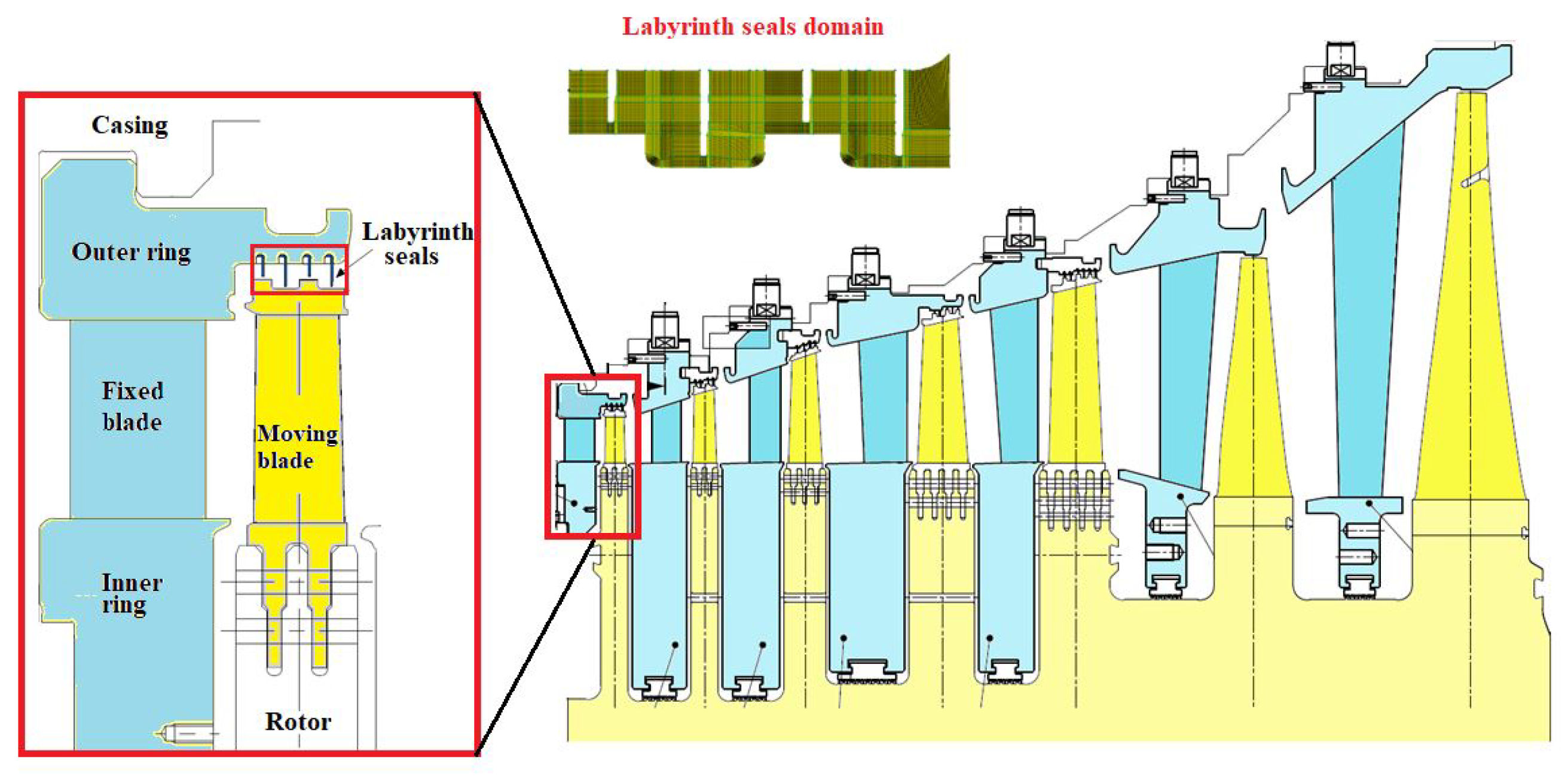
The steam channel of the reference turbine has seven blade stages, and the first five use straight seals. The last two stages of this turbine are discarded because they do not use straight seals and work under low pressure at the steam outlet. This study will focus on the analysis of the first stage.
Figure 3 shows the seven stages and the domain of interest.
To qualitative validate the model, first, the geometry of the channel was designed in CAD on a scale 10:1 to allowed visualizing the behavior of the fluid inside. The design was used to print a 3D model in PLA plastic. The 3D model was enclosed by two transparent acrylic walls showing the domain of interest (
Figure 4). After that, smoke was injected with a tracer to observe the flow behavior. The performance of the model is similar to the description of Darshan et al. [
9], who noticed that the vorticities are created in each chamber and described the path taken by the vapor in this type of seal, finding six vortexes in total.
2.2. Optimization Design Process of the Seal
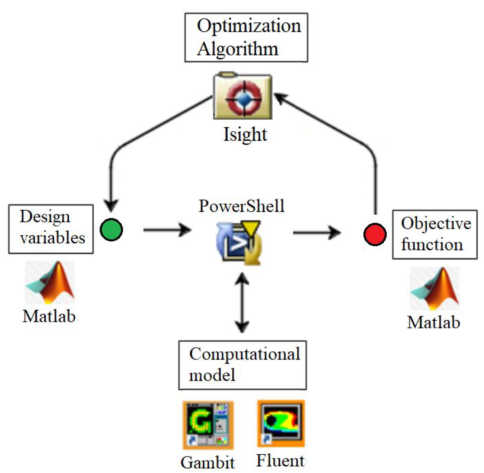
As was presented in the research of Herrera et al. [
11] and Galván et al. [
12], the design of a PowerShell script can coupled using the coupling of Isight, Matlab, Gambit, and Fluent software converting the problem into an automatic optimization process (See
Figure 5).
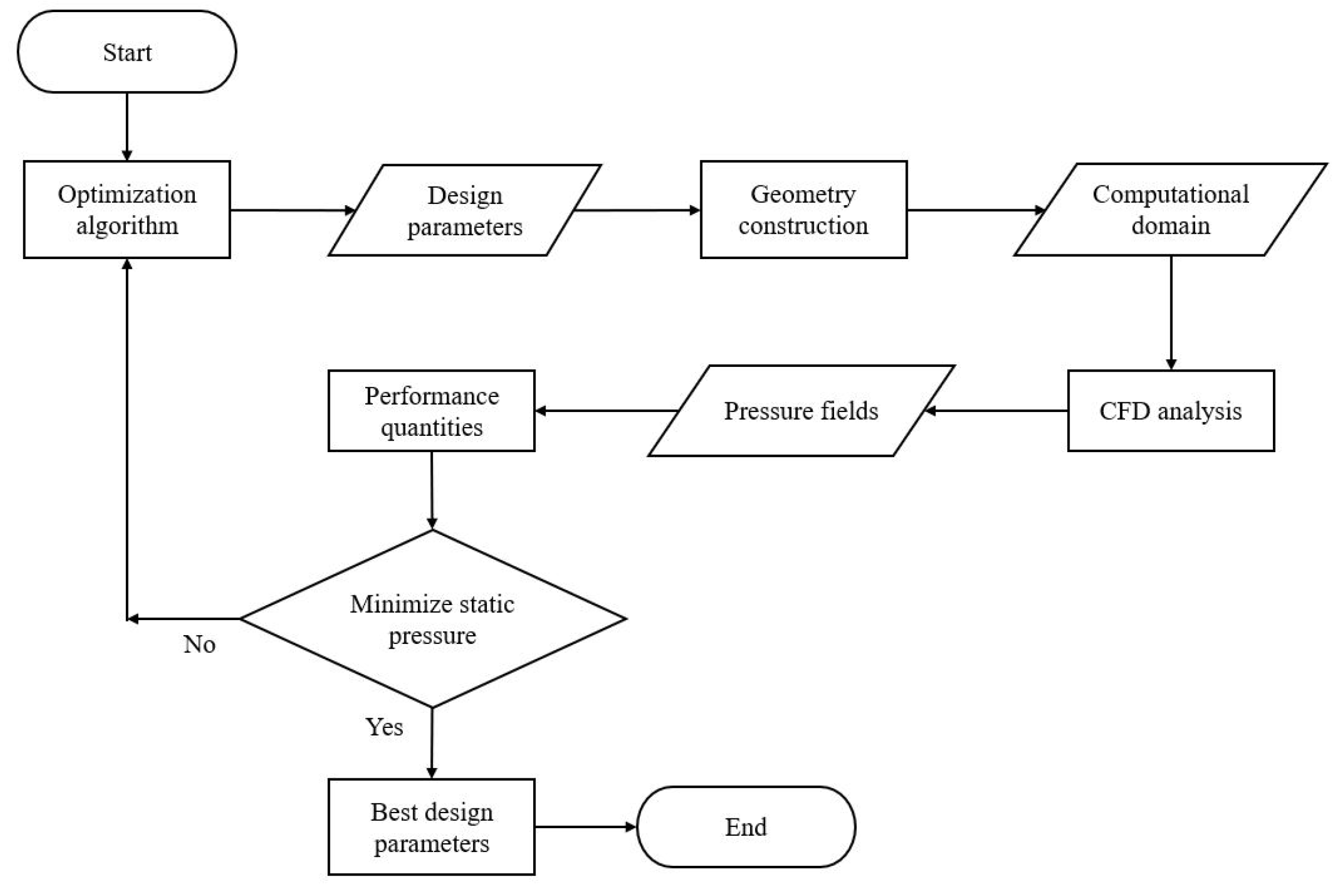
The optimization process is described in the next steps:
PowerShell starts the process when Isight, through an optimization algorithm, assigns an initial value to each design variable using a data file.
PowerShell commands Matlab to read the file which contains the parameters for the seal profile.
Matlab writes the coordinates for the seal shape and generates an output file.
The main program (PowerShell) receives this information, prompting Gambit to execute a sequence of instructions to generate the computational domain, including the topology, mesh, and boundaries.
Gambit develops a mesh file that Fluent uses to start the numerical solution.
Fluent returns a data file with results from the computational domain, including the values of the static pressure at the outlet, which were previously used to define the objective function.
Matlab reads this file and compares the objective function against a reference value calculated in the previous step.
Isight reads and evaluates these data, starting the process again and assigning new values to the design variables of the new seal profile.
The optimization ends when the automatic process completes the preset number of cycles.
Figure 6 illustrates each step of the adapted methodology for redesigning the steam turbine seals.
2.3. Validation of the Optimization Steps
Evaluating each optimization strategy is fundamental to guarantee the reliability of the proposed methodology. This section presents the evaluation of each step of the optimization, which are:
The geometry parameterization uses a single input parameter.
The computational model of the domain.
The parameters of the optimization algorithm.
The single-value objective function approach.
2.3.1. Geometry Parameterization
Clearance tolerances are typically 1.0 mm or less for High-Pressure (HP) turbines, increasing to more than 2.0 mm for a sealing system in Low-Pressure (LP) turbine stages [
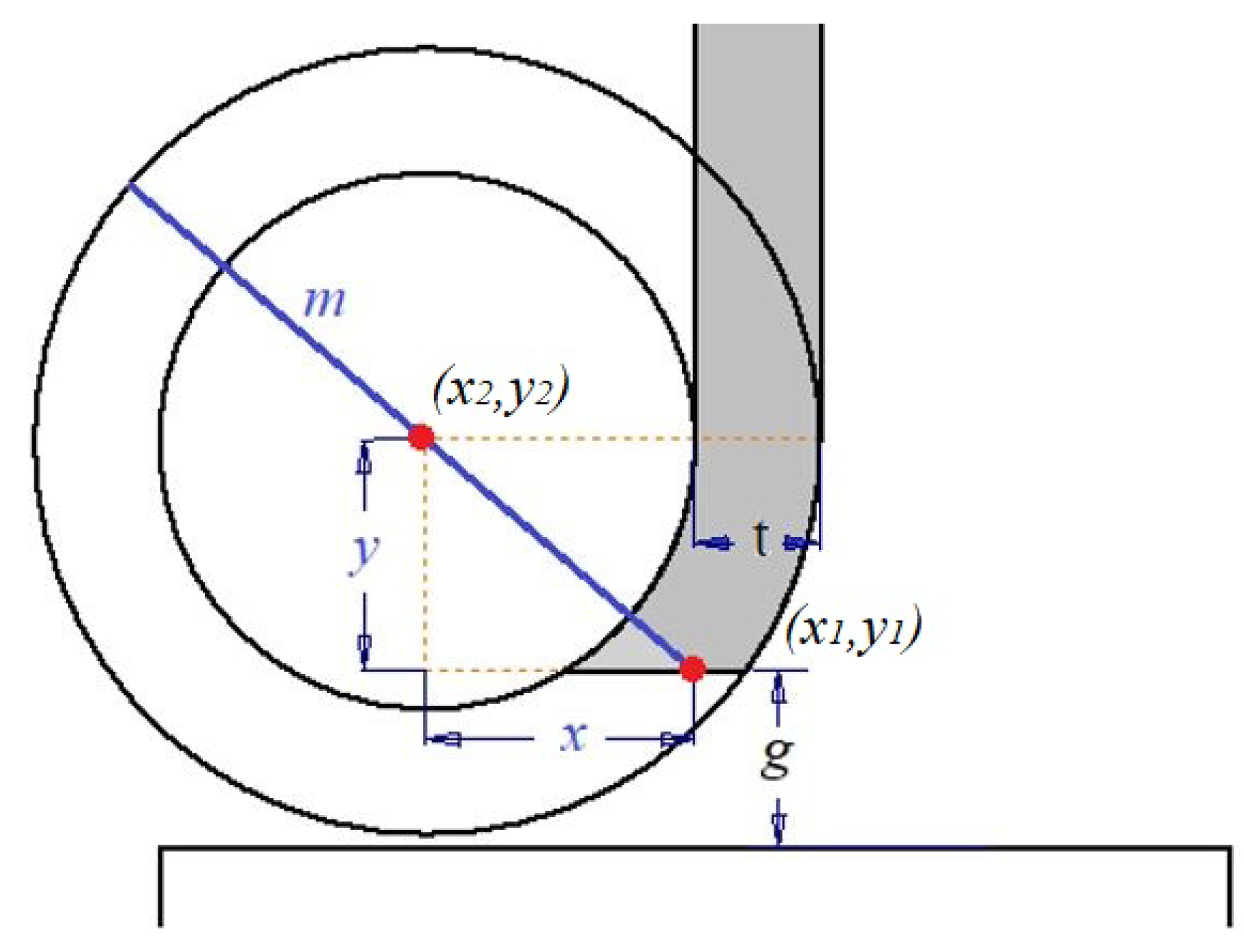
4]. Based on the coordinates that will be defined for our parameterization, two circles are created to form the geometry of the leading edge of the seal automatically, the position and curvature of the stamp can be varied, and the slope Equation (
1) points to the line to locates the second point that defines the path of the two concentric circles, to form the leading edge of the labyrinth seal.
According to the steam turbine’s original design, the there are some established geometrical restriction for the problem statement, the clearance between the rotor disc (
mm ) and the seal thickness (
mm). Thus, x-y coordinates were defined to draw concentric circles, as shown in
Figure 7, where the shaded area represents the new seal geometry.
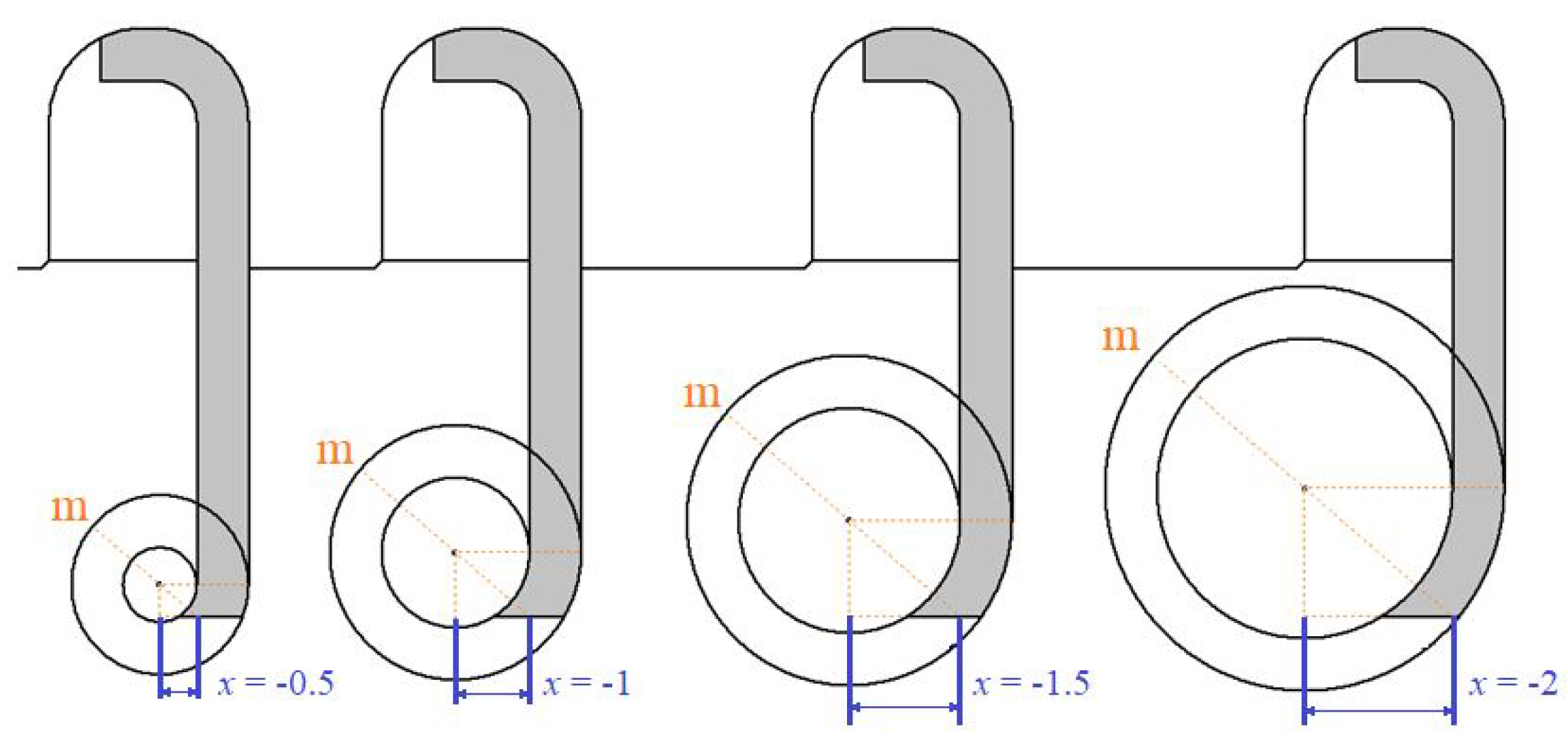
Table 1 shows the value design of slope
m and the coordinate
x that defines the position for the edge of attack. The range of design of the variables must maintain a realistic geometry configuration.
Figure 8 shows the geometry evolution of the seals’ leading edge by using different values of the geometrical parameter in
x direction. The adjustment of the seal geometry is made automatically by modifying the
x variable with the Isight optimizer program.
2.3.2. Computational Model
CFD helps to analyze many design configurations in a relatively short time [
13]. This work uses this tool in a two-dimensional analysis because previous results justify the case of study as axial symmetric [
14]. The computational model considers compressible flow, a conservative form of the Navier-Stokes equations, and along with the k -
model a high Reynolds number used by Xi et al. [
14] and Mohammadi et al.[
15]. Equation (
2) can be used in turbomachinery seals, where the steam is a perfect gas and considering the problem state equation,
where
P is the pressure,
is the compressibility factor,
is the density,
R is the universal gas constant, and
T the temperature.
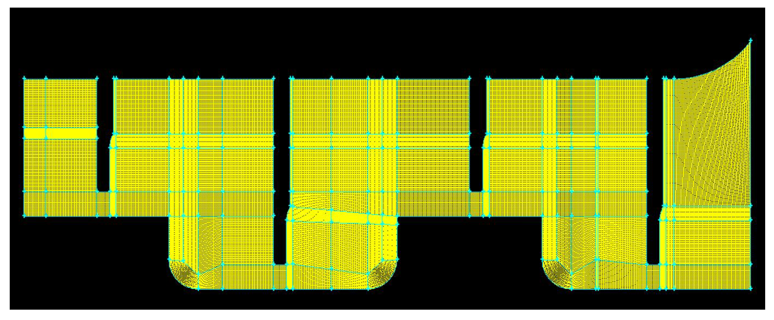
Gambit software was used to create the domain geometry and to generate a structured mesh according to
Figure 9 to control the number of elements and their dimensions, the quality, and the convergence criteria [
16]. Multiblock mesh (
Figure 9) with 8332 elements was the mesh reference that provided suitable conditions (rapid construction of fewer elements and easy manipulation) for adaptation to the automatic optimization process.
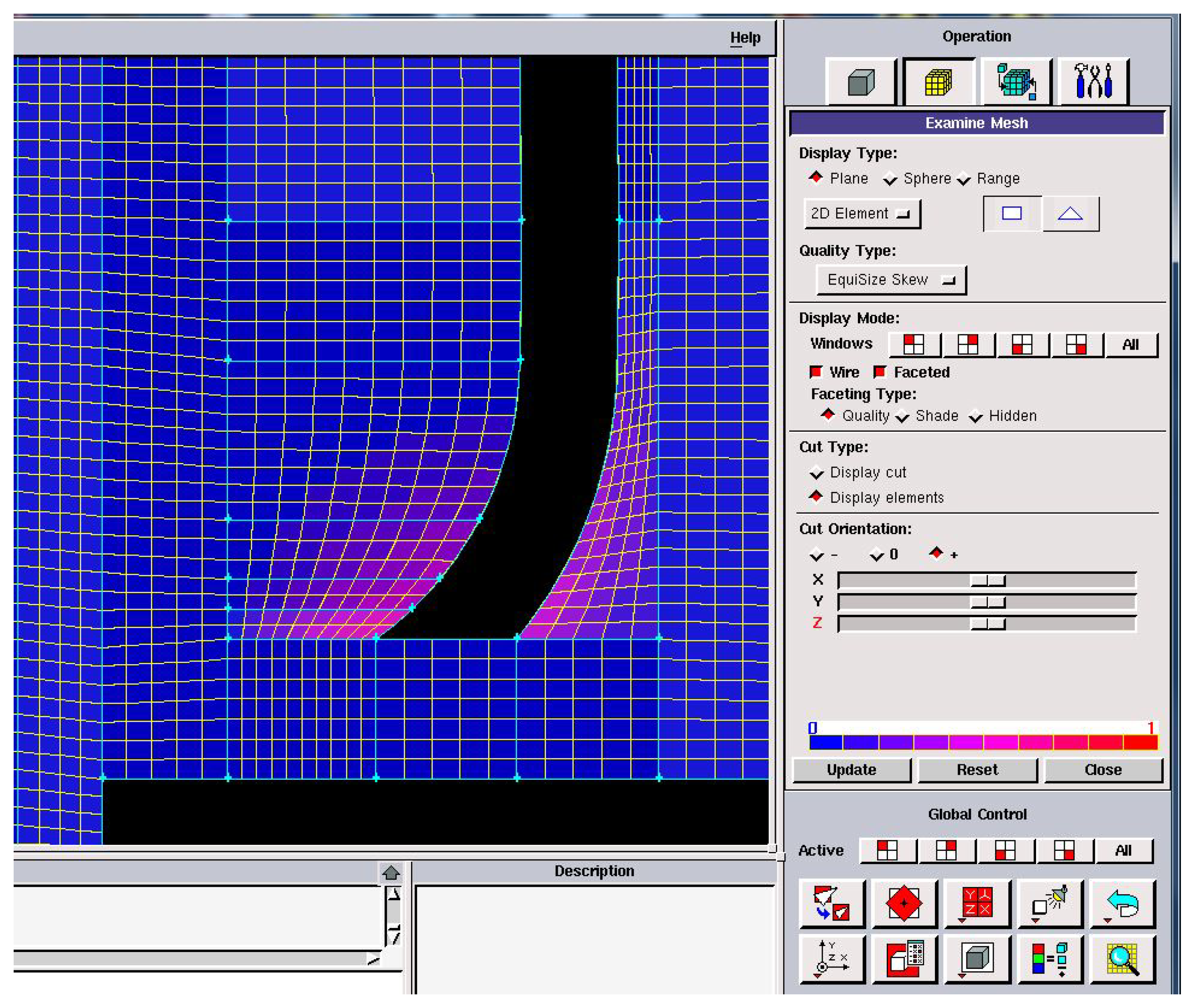
Figure 10 presents a 0.53 skew size of the mesh quality in the 17 most deformed elements.
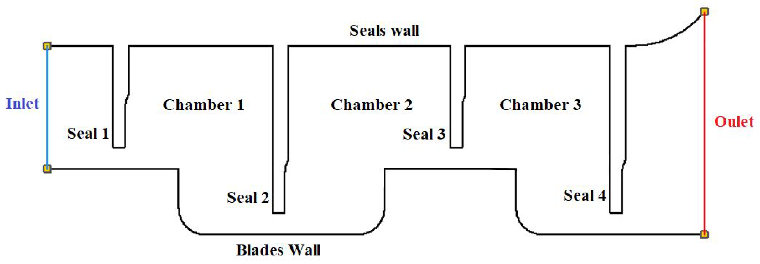
Figure 11 depicts the fluid and solid domain of the seal system and its boundaries for the simulation in Ansys software.
Table 2 presents the operating parameters of the reference geothermal turbine and the steam conditions applied to the inlet boundary. The uniform distribution of the steam pressure injection along the inlet and outlet area of the system, suggested the axi-symmetrical condition used by Chakravarthy et al. [
17]. This condition adapts the two-dimensional analysis along the labyrinth channel.
2.3.3. Optimization Algorithm
Optimization aims at finding the condition that returns a maximum or minimum value of a specific function. In our case, we intended to obtain the minimum value in the outlet static pressure using the analogy of the biological evolution through genetics as the adaptive processes implemented in the computer system [
16]. In this way, Genetic Algorithms (GA) have been an adaptive method for solving shape design optimization problems. The power of GAs comes from their robust technique in solving various problems from different areas. The multi-island parallel model is a simple sequential GA with regular exchanges of subpopulations between islands according to the pre-established number of generations and some defined parameters [
18].
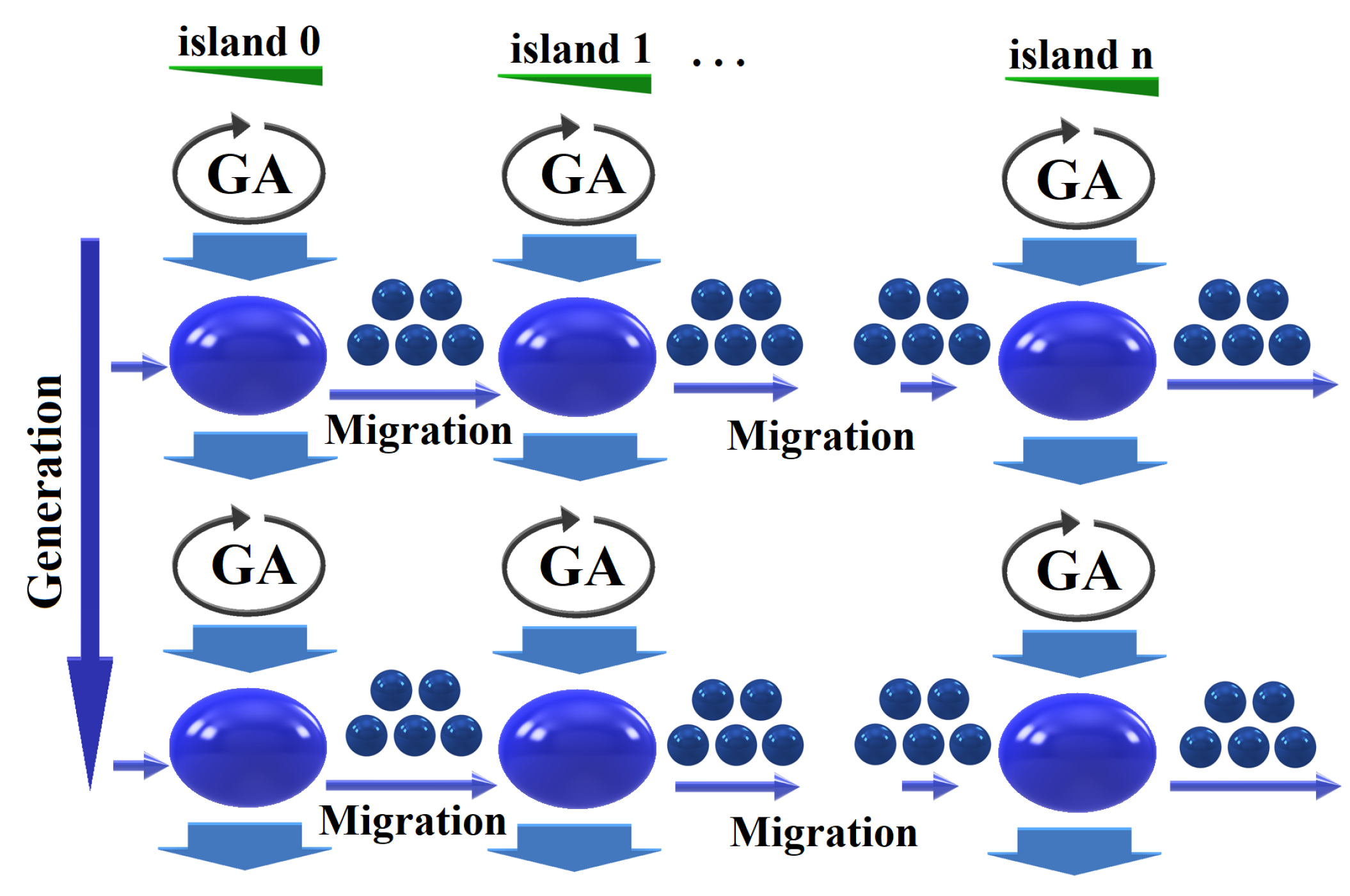
Figure 12 shows how individuals are divided into subpopulations that evolve in a parallel and independent manner through migrations, allowing the exchange of genetic material. Moreover, elitism guarantees that the best genetic material is carried through the generations, preserving the previous generation best individual without alteration.
Bearing in mind the features of the honed genetic algorithm, it was used a multi-island model, which has been implemented in a parallel and distributed computing system. For the distribution, three individuals (designs) were grouped in three islands using three generations, obtaining 27 evaluations that ran in parallel until the end of the process. The calculation nodes distributed the workload, and then each node parallelized the computational domain of each new seal design with the Isight optimizer program.
2.3.4. The Objective Function
The main objective of this research is to find a seal whose shape allows an increase of the number of vortices in the pressure chambers to produce an increase of the difference in the pressure values between the inlet and the outlet. The geometric inclination of the seals leading edge will modify the flow trajectory inside each chamber, which should affect the static pressure loss. According to Soemarwoto et al. [
19], this capacity for varying the pressure loss is a characteristic or property of the seal. Thus, the total pressure loss in normalized form (Equation
3), has been established as the objective function
where the reference total pressure
corresponds to the inlet pressure condition, and the total pressure
at the outlet of the seal is defined in the Equation (
4).
where
is a ratio of specific heats
= 1.4, and
M is Mach Number.
In this study, FLUENT software calculates the pressure fields at the domain’s exit boundary, and MATLAB processes this information to obtain the final value of the objective function.
3. Results
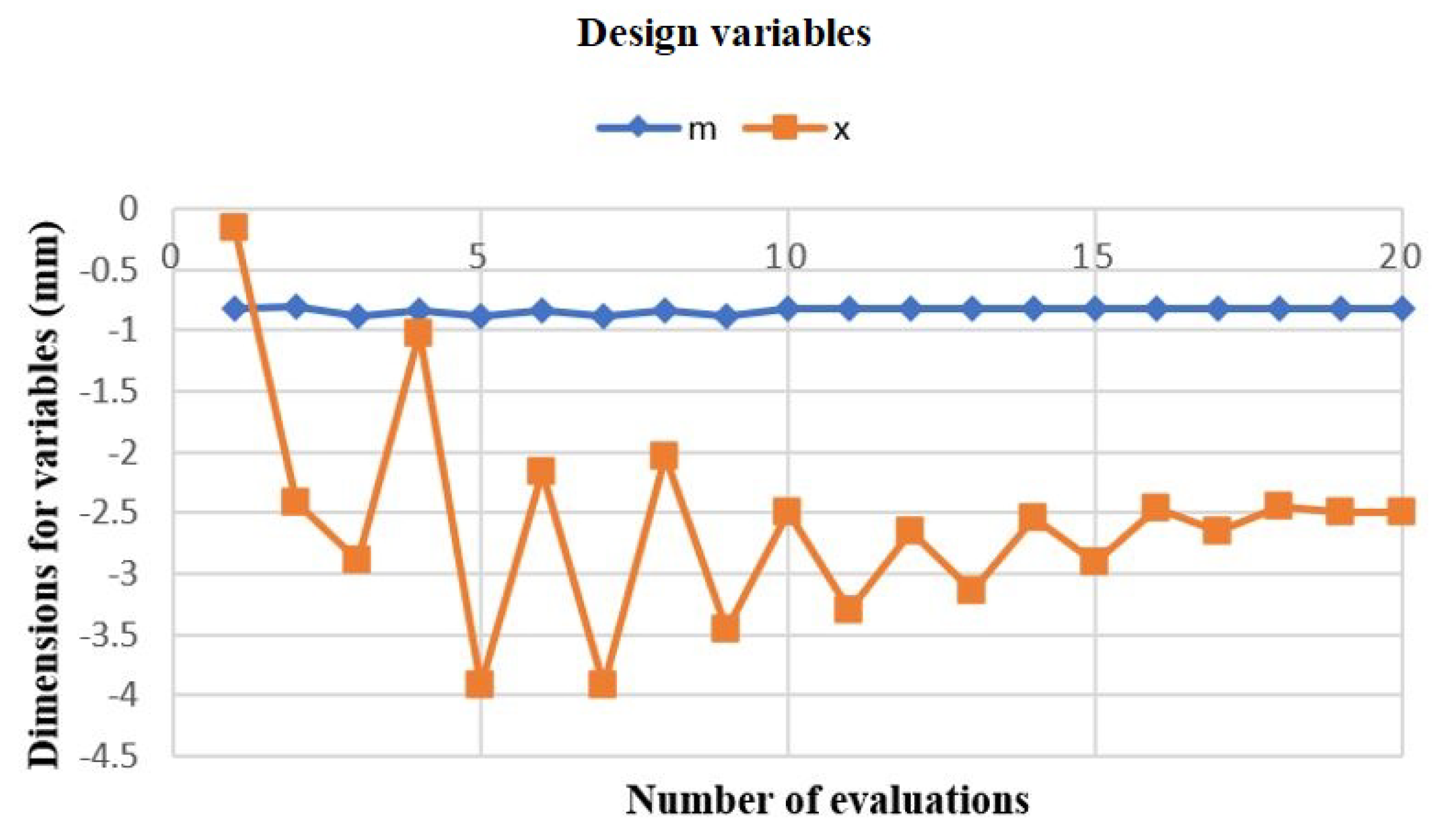
Figure 13 shows the behavior of the design variables
x and
m throughout the optimization process. Starting from a straight seal with coordinate
x = -0.001 as an initial value to avoid instability and reaching a final value of
, that is the
x coordinate causes the seal to hit the top wall.
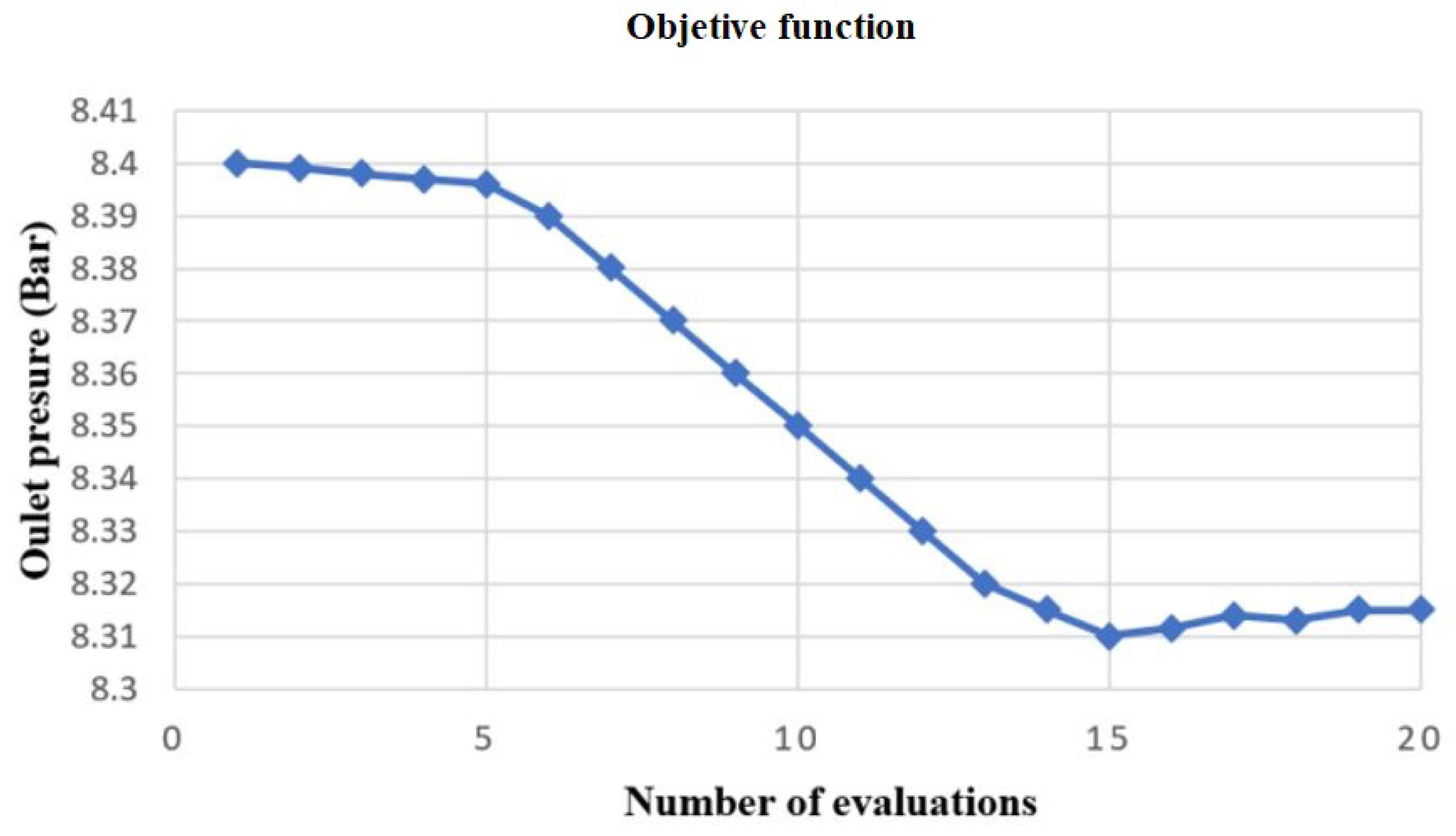
Figure 14 presents the variation of the outlet pressure throughout the entire process. The results of this optimization show that the outlet pressure reduction reaches 1% using 20 evaluations in the optimization process.
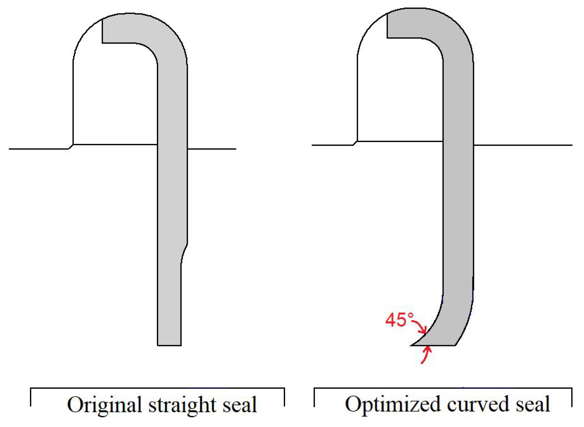
Figure 15 compares the original and the optimized geometry. The optimization process results show that the best geometry for the leading edge tends to an inclination of 45° and a magnitude of
for the variable
x as shown in
Figure 8.
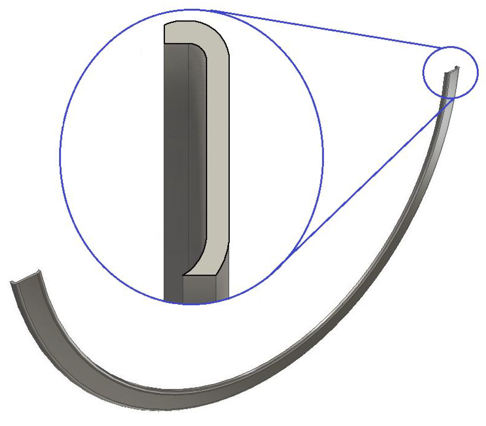
Figure 16 presents the 3D CAD model geometry generated in the optimization process; the shape defines the leading edge and the geometric aspects of the new inclined geometry of the seal in a section view.
3.1. Flow Analysis of the Original and Optimized Seal Models
In this section, using CFD, the flow is analyzed throughout the computational domain, comparing the original straight seal and the new one curved geometry,
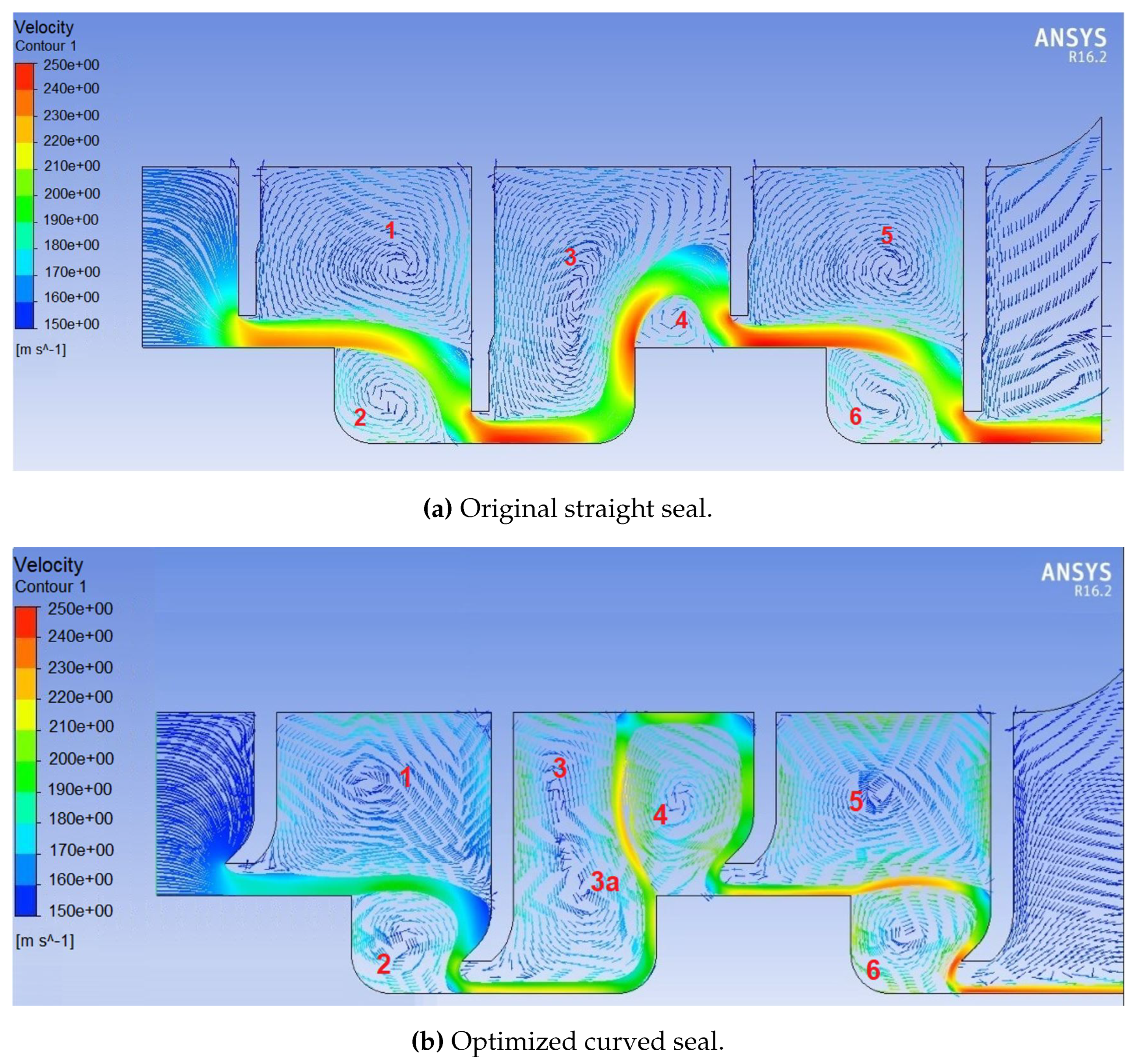
Figure 17 shows the velocity field comparison between different shape geometries. For the original seal, the simulation yields six vortices. However, in chamber two, the optimized curved seal shows the bipartition of vortex three and the growth of vortex four, giving the steam a longer path to flow from the entrance. Also, the new seal considerably reduced the size of the leakage jet since the first seal and the flow velocity through the gaps. The speed of the steam leaving chamber three provoked an increase in turbulence intensity. The steam jet has a longer trajectory and loses speed as it sticks to the walls, decreasing the pressure ratio concerning the outlet.
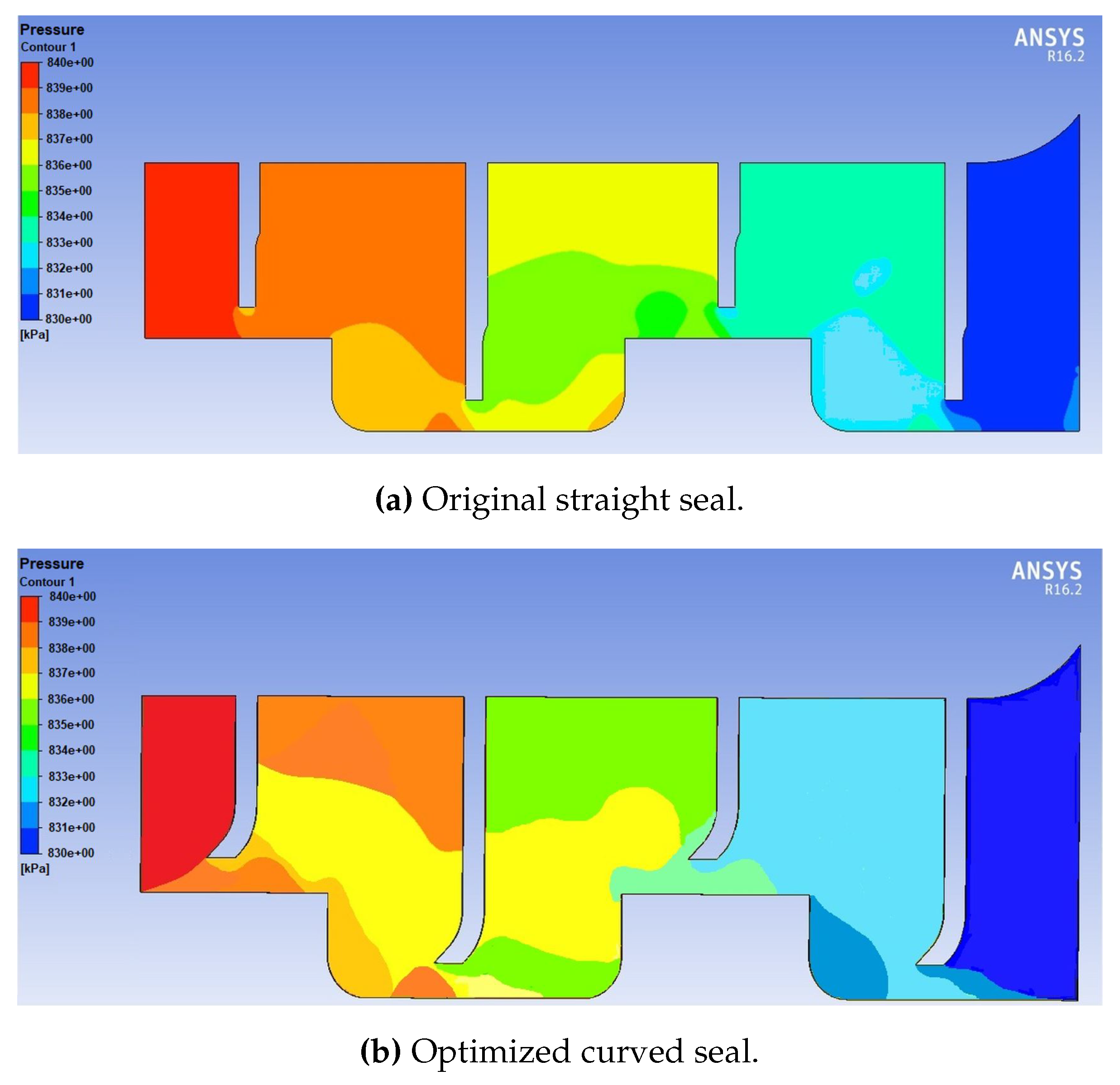
Figure 18 compares the static pressure intensity in each seal chamber. The optimized seal increases the zone of lower pressure in chamber one. In chambers two and three the same effect occurs.
4. Discussion
The pressure ratio decreased by approximately in the Fluent cases, and we maintained a seal geometry that, although inclined, is feasible to manufacture with current technology.
Zhang et al. [
20] improved the efficiency of the seal system reducing the steam leakage by
to
, but increasing the seal number. However, manufacturing the proposed geometric shapes with current commercial technology would be complicated. Kim et al. [
13] increased the number of seals to reduce the pressure ratio with the staggering method. Cases were analyzed that employed a leading-edge configuration but utilized regular geometries for the seal tip, similar to the study conducted by Dogu et al. [
8] Some seal designs, such as the mushroom type, are challenging to manufacture.
The results presented in this work thus confirm that redesigning the seals shape, using the coupling of different software controlled by an optimization algorithm, could be established as a straightforward methodology to reach the ideal geometric seal profile with realistic manufacturing possibilities.
5. Conclusions
This research presented the numerical optimization of a new seal shape given by a 2D asymmetrical CFD model as an evaluator of the flow within the domain of interest.
Comparison between straight and inclined seals showed a significant change in the steam’s flow behavior along the back pressure chambers. Increasing the number of vortices was fundamental to achieving a pressure reduction. Another critical factor was the permanence of the steam in the chambers; the longer the steam travels, the pressure in the chamber decreases proportionally.
Despite its simplicity, we recommended improving the numerical model to make it more robust and computationally accessible to increase the number of process evaluations. Besides having a valid reference of the flow behavior inside the seals, the optimized shape could analyze the ideal flow characteristics inside the chamber by creating a high-fidelity numerical model since there is no experimental data.
Finally, the methodology presented in this work could contribute to re-powering turbines by designing new shapes or applying them to other forms of seals, making the energy transfer in each turbine step more efficient.
Author Contributions
Conceptualization, M.A.T.-S. and S.R.G.-G.; Methodology, M.A.T.-S., S.R.G.G. and Á.C.-S.; Software, M.A.T.-S. and Á.C.-S.Validation, M.A.T.-S. and S.R.G.-G.; Formal Analysis,M.A.T.-S. and S.R.G.-G.; Investigation, M.A.T.-S. and S.R.G.-G.; Resources, S.R.G.-G. and H.A.-R.; Data Curation, M.A.T.-S. and Á.C.-S.; Writing—Original Draft Preparation, M.A.T.-S., S.R.G.-G. and Á.C.-S.; Writing—Review and Editing, M.A.T.-S., S.R.G.-G., Á.C.-S., H.A.-R. and F.J.D.-M.; Visualization, M.A.T.-S. and S.R.G.-G.; Supervision, S.R.G.-G., H.A.-R. and F.J.D.-M.; Project Administration, S.R.G.-G.; Funding Acquisition, S.R.G.-G., H.A.-R. and F.J.D.-M. All authors have read and agreed to the published version of the manuscript.
Funding
The author(s) disclosed receipt of the following financial support for the research of this article: this work was supported by scholarship (No.CVU: 892917) from the Consejo Nacional de Humanidades, Ciencia y Tecnología (CONAHCyT).
Data Availability Statement
The data used and presented in this research could be made available on request.
Acknowledgments
The authors express their gratitude to the Universidad Michoacana de San Nicolás de Hidalgo (UMSNH) and its Faculty of Mechanical Engineering and the CONSEJO NACIONAL DE HUMANIDADES CIENCIA Y TECNOLOGIA CONAHCyT of Mexico for the financial support.
Conflicts of Interest
The authors declare no conflicts of interest.
Abbreviations
The following abbreviations are used in this manuscript:
| CAD |
Computer-Aided Design |
| CFD |
Computational Fluid Dynamics |
| GA |
Genetic Algorithms |
| HP |
High Pressure |
| LP |
Low Pressure |
| MIGA |
Multi-Island Genetic Algorithm |
| MW |
Mega Watts |
| PLA |
Polylactic acid |
|
Total pressure |
| Latin Symbols |
|
| m |
Slope of the line |
| M |
Mach Number |
| P |
Pressure |
| R |
Universal gas constant |
| T |
Temperature °C |
| x |
Coordinate on the x axis |
| y |
Coordinate on the y axis |
|
Total pressure |
| Greek symbols |
|
|
Turbulence kinetic energy |
|
Dissipation rate of turbulence pulsation kinetic-energy. |
|
The gas compressibility factor |
|
Density |
References
- Kaszowski, P.; Dzida, M.; Krzyślak, P. Calculations of labyrinth seals with and without diagnostic extraction in fluid-flow machines. Polish Maritime Research 2013, 20, 34–38. [Google Scholar] [CrossRef]
- Tanuma, T. Advances in steam turbines for modern power plants. In Advances in Steam Turbines for Modern Power Plants; Elsevier: Amsterdam, Netherlands, 2016; pp. 1–9. [Google Scholar]
- Turnquist, N.; Ray, F.; et al. Brush Seals for Improved Steam turbine performance, 2005 NASA Seal/Secondary Air System Workshop, , p.107 2006 Volume 1 NASA/CP—2006-214383/VOL 1. [CrossRef]. 1 October.
- Stephen, D.; Hogg, S.I. Development of Brush Seal Technology for Steam Turbine Retrofit Applications. In Proceedings of the 2003 International Joint Power Generation Conference, Atlanta, GA, USA, 16-19 June 2003; pp. 505–512. [Google Scholar]
- Yu, X.L.; Lv, Q. ; Pang Y-C,: Wang K,; Jin L-W.; Lu Z.; Study on Labyrinth Seal Leakage Flow With Piston Eccentric Motion in a Labyrinth Compressor. Journal of the Chinese Society of Mechanical Engineers 2020, Vol.41,
623–626.
- Aslan-zada, F.E.; Mammadov, V.A.; Dohnal, F. Brush seals and labyrinth seals in gas turbine applications. Proceedings of the Institution of Mechanical Engineers, Part A: Journal of Power and Energy 2013, 227, 216–230. [Google Scholar] [CrossRef]
- Ayyalasomayajula, S.K. A Numerical Study of Curved Labyrinth Seals for Steam Turbines. Master’s Thesis, University of Tennessee - Knoxville, TN, USA, 2005. [Google Scholar]
- Dogu, Y.; Sertcakan, M.; Gezer, K.; Kocagül, M.; Arikan, E. : Ozmusul, M. Labyrinth seal leakage degradation due to various types of wear. Journal of Engineering for Gas Turbines and Power 2017, Vol. 139,11−−13.
- Darshan, P. A Study of Curved Labyrinth Seals for Steam Turbines. International Advanced Research Journal in Science, Engineering and Technology 2016, Vol.3.
- Gutiérrez-Negrin,L.C.A. Current status of geothermal-electric productionin Mexico. IOP ConferenceSeries: Earth and Environmental Science 2019, Vol.249.
- Herrera, N.; Galván, S.; Camacho, J.; Solorio, G.; Aguilar, A. Automatic shape optimization of a conical-duct diffuser using a distributed computing algorithm. Journal of the Brazilian Society of Mechanical Sciences and Engineering 2017, Vol.39, 4367--4378.
- Galván, S.; Reggio, M.; Guibault, F. Optimization of the inlet velocity profile in a conical diffuser. In Proceedings of the ASME Fluids Engineering Division Summer Meeting, Rio Grande, Puerto Rico, USA, 8-12 July 2012; pp. 125--134.
- Kim, T.S.; Cha, K.S. Comparative analysis of the influence of labyrinth seal configuration on leakage behavior. Journal of Mechanical Science and Technology 2009, Vol.23, 2830--2838.
- Xi, J.; Rhode, D.L. Rotordynamics of Turbine Labyrinth Seals with Rotor Axial Shifting. International Journal of Rotating Machinery 2006, 1--11.
- Mohammadi, B.; Pironneau, O. Applied Shape Optimization for Fluids, 2nd edn.; Oxford University Press: Oxford, UK, 2010; pp. 154--196.
- Fernández Oro, J.M. Técnicas numéricas en ingeniería de fluidos: introducción a la dinámica de fluidos computacional (CFD) por el método de volúmenes finitos; Ediciones Díaz de Santos: Madrid, Spain, 2012, ISBN: 9788429126020.
- Chakravarthy, L.K.; Srikanth, P. Modeling & Analysis of Labyrinth Seals Used in Steam Turbines. International Journal of Scientific and Research 2015, vol.4, 1808--1813. Paper ID: SUB155787.
- Ch, R.P.; P, J.G.; G, E.L. GRISLAS: Un algoritmo genético paralelo que combina los modelos de grillas e islas para encontrar soluciones óptimas cercanas al problema del agente viajero. Universidad Nacional de Colombia 2008, 5, 8.
- Soemarwoto, B.I.; Kok, J.C.; de Cock, K.M.J.; Kloosterman, A.B.;Kool,G.A.; Versluis J.F.A.; Performance evaluation of gas turbine labyrinth seals using computational fluid dynamics. In Proceedings of the ASME Turbo Expo, Montreal, QC, Canada, 14-17 May 2007; pp. 1207--1217.
- Zhang, M.; Yang, J.; Xu, W.; Xi "Leakage and rotordynamic performance of a mixed labyrinth seal compared with that of a staggered labyrunth seal"; Journal of Mechanical Science and Technology 31 (5) 2261-2277 pp 2262 (2017).
|
Disclaimer/Publisher’s Note: The statements, opinions and data contained in all publications are solely those of the individual author(s) and contributor(s) and not of MDPI and/or the editor(s). MDPI and/or the editor(s) disclaim responsibility for any injury to people or property resulting from any ideas, methods, instructions or products referred to in the content. |
© 2024 by the authors. Licensee MDPI, Basel, Switzerland. This article is an open access article distributed under the terms and conditions of the Creative Commons Attribution (CC BY) license (http://creativecommons.org/licenses/by/4.0/).
