1. Introduction
In recent years there has been an increase of interest in the study and development of Unmanned Aerial Vehicles (UAVs) due to their suitability in many possible applications. They are being used in civil and commercial fields as well as in military operations such as intelligence, surveillance and reconnaissance missions. The capability to autonomously carry out these operations results to be a key factor: UAVs must have path planning and tracking algorithms as well as accurate and robust guidance laws and automation onboard.
In these applications autonomously following a predefined flight route is a basic requirement for the aircraft. Path following control causes the UAV to converge and follow a desired path with no temporal constraints.
The flight control algorithm should guarantee accuracy for the path following as well as robustness to wind disturbances[
1].
Several techniques have been investigated for the path following problem. These techniques can be divided into two categories: VTP (Virtual Target Point) techniques and control methods. The firsts exploit geometric approaches to generate virtual targets upon the path to be tracked real time[
2,
3].
Generally, in commercial off-the-shelf autopilots these techniques are the most popular for path following problem because of their simplicity and easy implementability. The control methods rely on nonlinear control theory to directly define the command signal[
4,
5,
6,
7]. Unlike the previous category where moving points are pursued, the latter make the crosstrack error of the UAV converge to zero while maintaining a preset airspeed. To the latter category for example belongs the Vector Field (VF) technique, which involves designing a vector field to guide the aircraft on the desired path even in the presence of a constant wind disturbance [
8], as well as the Sliding Mode Control (SMC), which is a nonlinear control technique with significant robustness properties. In [
9] nested saturation theory is applied to chase straight line and orbit path in windy conditions by developing strategies with constraints on attitude and flight path angles.
The study presented in this paper is based on the vector field notion but implements a further extension through a guidance law according to sliding mode control with the intent of improving robustness and performance. From the combination of control theory and Lyapunov stability, zero asymptotic convergence of the tracking error is ensured even in the presence of constant wind disturbances. The fixed-wing guidance problem is formulated not only for straight line but also for orbit path, as already addressed in literature[
10,
11].
In this paper results of the proposed path following techniques were inferred using a MATLAB&Simulink® high-fidelity model that realizes an extremely reliable simulation of the six DoF dynamic behavior of a small fixed wing UAV[
12]. The adopted dynamic model can be divided into three parts:
the acquisition of measurements by the sensors is simulated through the introduction of uncertainties and internal disturbances on the dynamic quantities processed by the aerodynamic block;
the flight control system employs the guidance law to produce reference command signals for the nested PID controllers to drive motors and control surfaces of the UAV;
high-fidelity six DoF flight dynamics is processed by reproducing the aerodynamic behavior of the aircraft structure. The parameters of aerodynamics were derived from experimental measurements on the proposed UAV prototype and allow for the evaluation of the forces and moments acting due to flight and wind conditions.
Most path following strategies adopt a decomposition approach to the problem: first the path planning is operated as well as the determination of the desired trajectory, which is used as input to the control system. This approach corresponds to the Guidance, Navigation & Control (GNC) system shown in
Figure 1.
All mission specifications such as desired speed and flight direction are obtained from the Mission block. The route is determined by a series of time-independent target geographical locations called waypoints, whose reaching is imposed. The new target is provided to the Guidance block only when the previous one is reached, according to a waypoint-switching algorithm. The logic implemented with the guidance law allows the generation of references for the Control block, which exploits navigation measurements such as UAV pose and velocity to correct the flight direction and speed and compensate for the error from the planned path. Real flight conditions always involve the presence of wind, which proves to be a variable disturbance and highly difficult to predict. For small UAVs the operational wind speed is commonly between 20% and 50% of the desired airspeed. Based on these considerations an effective path following logic must guarantee the wind-generated disturbances to be tolerated by the aircraft both in the real world as well as in the simulated scenarios of this study. Wind with varying speeds was applied in the simulations in order to find the maximum wind tolerated by the proposed guidance laws and to obtain the corresponding indices of tracking performance to be presented.
2. Problem Statement
This chapter presents the guidance problem to be further investigated and solved. The aircraft must fly autonomously along a path that has been created through the definition of waypoints and realized as the set of segments joining two adjacent targets. Typical missions require the airspeed and altitude of the UAV to be kept constant[
13].
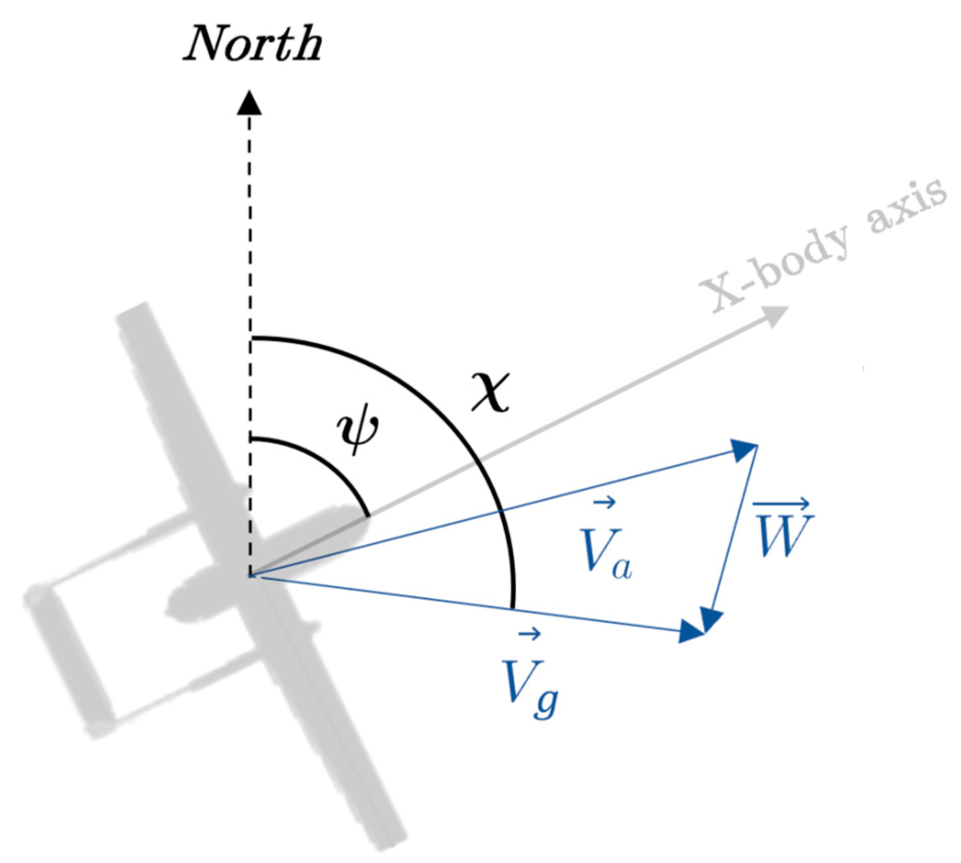
The proposed autopilot is provided with independent controllers for velocity and altitude corrections, therefore in this paper the problem formulation for the fixed-wing UAV assumes that speed and altitude are held constant. The geometric problem is formalized by referring to coordinates and notable variables shown in
Figure 2.
The heading
ψ and course
χ angles represent the orientation of the UAV nose and ground velocity with respect to North and they are generally controlled by guidance laws to ensure autonomous trajectory tracking. The navigation dynamic which is used to study the path following strategy can be represented in NED frame through the definition of the ground velocity
Vg (1), which differs from airspeed
Va by the vector sum of the wind velocity
W (
Figure 2).
Since Vg is an inertial-reference quantity it is more convenient to express the dynamics in terms of ground speed and course angle χ rather than airspeed Va and heading angle ψ to avoid wind dependence. Moreover, the latter are generically derived from airdata instruments with eventual wind estimators, while the firsts are directly derived from GPS system measurements decreasing uncertainties.
The objective of the case study is to design a method for accurate and robust path following in the presence of wind. The UAV must sequentially reach all waypoints with a specified tolerance while always keeping both angular and lateral-track error as low as possible. The guidance law must ensure proper execution of the planned trajectory along straight traits of slope ψw as well as upon orbit turns between them. The overall problem is thus decomposed into two subproblems for the path following:
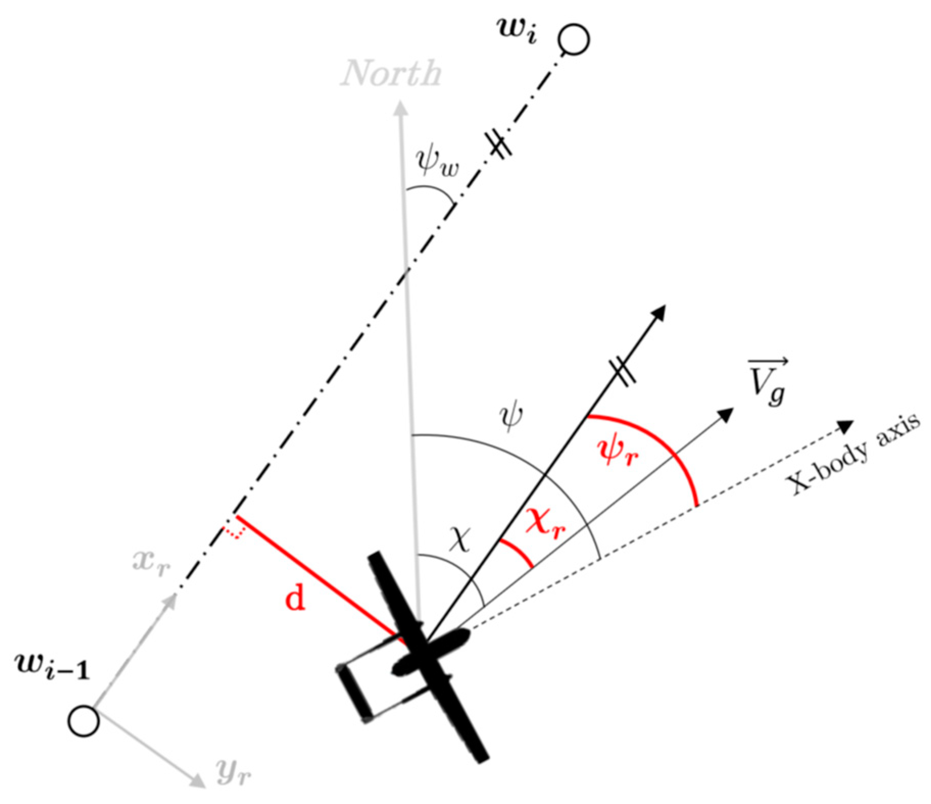
straight line, where in the desired path is defined as the trait joining two adjacent waypoints and where the UAV is expected to lie (
Figure 3);
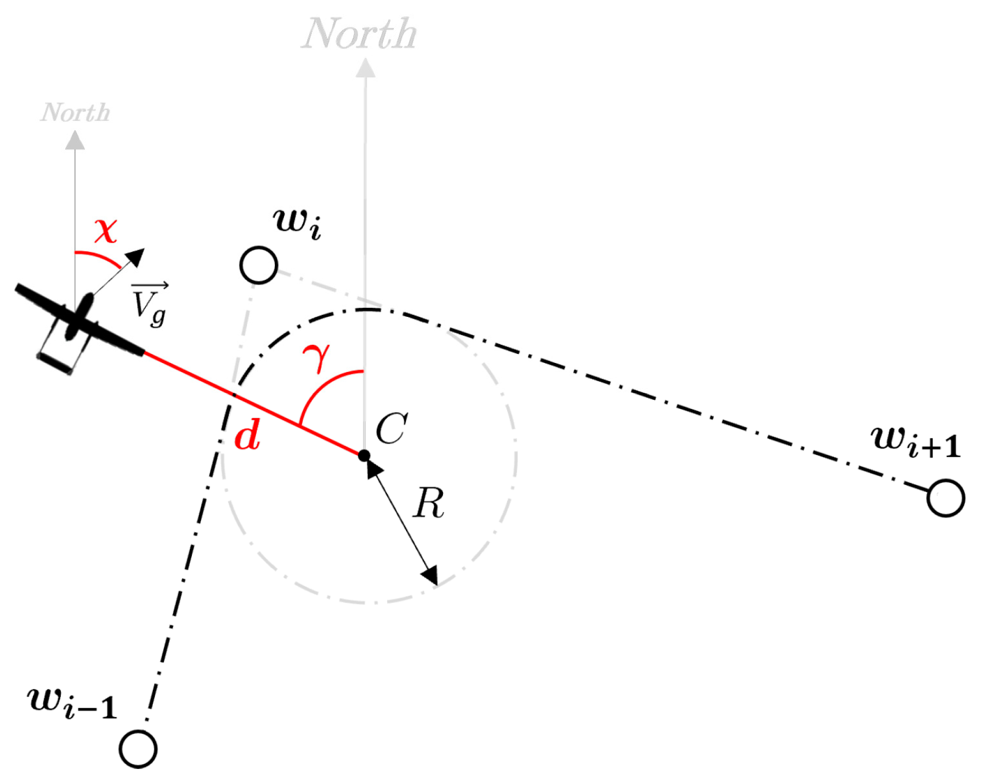
orbit path, wherein the desired path is defined as a circular orbit which can be traveled clockwise or counterclockwise at a constant distance from the center (
Figure 4).
The first consists in minimizing the cross-track error d with respect to the line wi−1 wi while simultaneously ensuring the convergence of the controlled angle χ −→ ψw.
In order to simplify its treatment the problem is formalized in a new reference frame r obtained by fixing the origin at wi−1 and imposing the axis xr on the straight line.
Due to this formulation the reference angle for control is always null and the d value is easily deduced from the
yr coordinate only.
Figure 3 shows the quantities of interest described above and the error variables related to heading angle
ψr and course angle χ
r, which will be used in the guidance laws along with the cross-track error.
The circular orbit problem is treated in accordance to the straight line one and involves following an arc of circle related to the angle between w
i−1,w
i and w
i+1. This implies that the aircraft must keep a constant distance from the centre and a tangent direction to the corresponding circumference. The autopilot guarantees the convergence of the desired angle
χ → γ + λπ/2, where
λ is a binary scalar associated with the clockwise or counter clockwise direction of orbit travel, and the distance from the orbit centre
C to be equal to the chosen radius
R of curvature. In this case the problem is evaluated in the original NED frame to avoid a moving reference during the turn. Referring to
Figure 4 the gamma angle
γ is defined as the angular position of the UAV with respect to the centre C while d as the distance from the same centre. These two variables are derived from a polar approach to the problem which results to be more suitable since the path geometry. Similarly to the first case the error variables used in the guidance law are derived as
χr = χ − γ + λ π/2 and
dr = d − R.
3. Path Following Guidance Laws
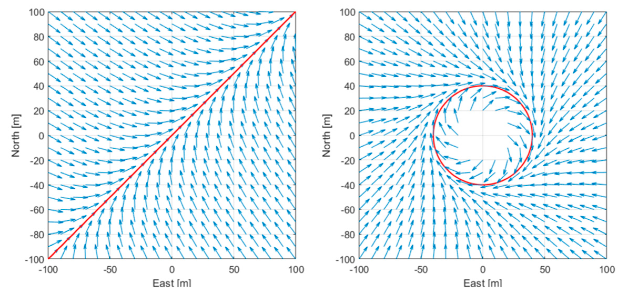
In order to address the previous problems, first a vector field must be constructed. A vector field U : S ⊆ Rn −→ Rn is a map that assigns a vector to each point of a space subset.
This method computes the vector field around the path to be followed by defining a set of desired course angles as a function of the UAV position in the XY plane. These references must point to the desired path in order to have convergence of the UAV towards the required route direction.
The notion of vector field is similar to potential field, which have been widely used as tool for path planning in the robotics community with the difference that the first does not necessarily represent the gradient of a potential but simply indicates a desired direction of flight.
The choice of a function σ(·) for the vector field implementation is of crucial importance because it must guarantee certain properties [
14]. In the case study a scalar function that associates the desired direction
χdes with the cross-track error
d is used (2).
The last condition shows how the controlled quantity is saturated to a constant value χ∞ for high values of d, while it changes accordingly when the cross-track error decreases.
This behavior is known as good helmsman behavior and it is well known in literature to better manage the trajectory [
14]. The vector field method is currently applied to paths composed of straight lines and arcs.
Figure 5 shows examples of vector fields for linear and circular paths.
As mentioned, the objective of the paper is to obtain an effective path following algorithm through the combination of vector field strategy with sliding mode control, which is addressed below. The term sliding mode refers to a state feedback variable structure controller that modifies the behavior of a nonlinear system by forcing it with a high-frequency control signal.
Consider the dynamics of the state variable
x of a nonlinear system and define the desired state
xdes and the corresponding error variable
x˜ = x − xdes, with respect to the control law is defined. In the present problem the time-variant sliding surface is defined through the scalar
sliding variable s by (3):
In the scalar case under consideration
s turns out to be described by(4)
The goal of sliding mode control can be summarized in the following features: bring the state to the sliding surface in a finite time and keep it above. The sliding mode is based on a feedback control made of two terms:
a model-based term built on the available model of the system, which in case of exact model knowledge guarantees the state to remain on the sliding surface;
a discontinuous term that forces the state on the surface in the case of drift and thus provides robustness against internal and external disturbances (e.g. model uncertainty and measurement noise).
This technique should ensure that the sliding surface is reached in a finite time and is never left, however in reality uncertainties on the model causes the systems not to lie exactly on the surface but within a boundary layer of limited width. The global attractiveness of the defined sliding surface is later ensured through Lyapunov stability theory [
15], indeed by choosing a positive-definite candidate function
V(5).
Asymptotic stability is guaranteed by the condition (6):
This condition guarantees state convergence on the sliding surface for both s < 0 and s > 0. In a real application the intrinsic delays of the system between the sign change of s and the control action contributes to enlarge the boundary layer.
3.1. Problem Dynamics
In the present section the overall dynamics of the notable quantities for the problem are investigated. In the field of fixed-wing aircraft turns are performed by exploiting a component of the aerodynamic lift that allows for acceleration in the lateral direction. In aeronautics ailerons are used to vary the lift force on wing surface and thus produce a moment along the x-body axis; since lift is always directed along the vertical direction, such motion tilts the vector towards the inside of the curve generating the necessary centripetal acceleration. In aviation this maneuver is referred to as banking or bank-to-turn, meaning the use of roll motion to induce the aircraft to turn [
16]. This maneuver yet causes a reduction in the vertical component of the aerodynamic force, which must remain sufficient to support the aircraft weight. For this reason, it is common in aerial applications to saturate the maximum allowable roll: in the present application UAV roll cannot exceed
±π/6 for flight stability reasons.
In steady state condition equations describing the banking maneuver result from balancing weight and centrifugal forces(7):
where
Vg is the ground speed,
R is the radius of curvature and
L is the lift force. The ratio of equations at (7)is known as
coordinated turn approximation(8).
In case of stationary turn (8) can be expressed as (9):
From the course definition
χ = χr + ψw and assuming the direction of the path invariant (9) becomes(10):
The other dynamics required for the guidance law design is relative to the cross-track error d, which is deduced from the geometry of the problem[
17]. Since
d is a position variable its dynamics is also dependent on the ground velocity according to(11):
3.2. Straight Line
The purpose of this study is designing a sliding mode control to the vector field strategy introduced above. In this particular section the straight path algorithm is addressed. In order to implement the vect, or field the arctan function was chosen since in spite of its simplicity it allows the properties at (2) to be respected[
8]. The vector field for the desired angle is expressed as (12).
where
χ∞ denotes the value of saturation for high values of
d, which in our case was chosen to be equal to
π/4 , according to the good helmsman behaviour. The parameter
k defines the slope of the trajectory around zero instead, and thus for small lateral-track errors. In order to avoid excessive control efforts,
k cannot be chosen arbitrarily large despite being beneficial for tracking performance nearby the desired path.According to Equation (4) the sliding surface can be designed as (13) whose dynamic is expressed by(14)
In order to define the guidance law it is necessary to infer the model-based and discontinuous terms. In case of exact knowledge of the model the continuous term would guarantee a constant
s and thus the stability of the equilibrium point. Referring to Equations (10) and (11) for dynamics and imposing (14) to be zero, it is obtained(15)
The model-based term ϕmb of the command signal that verifies this condition is the following one (16)
The discontinuous term allows rejection of measurement and model uncertainties and ensures asymptotic convergence to the desired equilibrium point. The function chosen for this purpose is
k sign(s), which completes the command signal
ϕdes. The overall guidance law is finally expressed as (17):
The general demonstration of asymptotic stability, viable for both the straight and circular paths, is deferred later.
3.3. Orbit Path
In the problem formulation both straight lines and circular arcs were shown as feasible paths to be follow. The reference vector field is designed similarly to the previous case. The geometry of the orbit is defined by a fixed center and a constant radius. The implemented algorithm must command the ground speed towards the center for high distances from the predefined path (
χ∞ = π/2 ), while as the distance decreases in a direction tangent to the arc. From these considerations the desired course is chosen as(18)
where R is the radius of the orbit,
λ generalizes the formulation with respect to the direction of rotation around the center and
k is the parameter specifying the transition rate from
γ − π and
γ − λ π/2 . The analysis of the problem as polar formulation requires the dynamics of the corresponding variables
dd/dt and
dγ/dt . The latter indicates the velocity relative to the orbit and it is thus defined as(19):
In analogy with (11) is obtained(20):
Equivalently to what was done for the straight path, the sliding surface and its dynamics for the specific case are derived
Again the continuous term is determined by imposing in(23) surface dynamics invariant and substituting Equations (10), (19) and (20).
From (23) the model based term
ϕmb is derived (24)
The resulting command signal
ϕdes inclusive of the discontinuous term is expressed as(25)
The (17) together with the (25) allow precise following of a path realized as the combination of straight and circular sections. Regardless of the definition of surface and path geometry, a generalized demonstration of Lyapunov stability can be arranged. As mentioned in the theory above asymptotic stability is guaranteed by condition (6). In both cases substituting the control signal
ϕdes in the
ds/dt equation results(26)
The stability condition is described by(27) ,considering the implementation of sign operator as ratio between signed and unsigned value of
s.
which is always verified for
κ > 0. This proves to be a sufficient condition for the attractivity of both the sliding surfaces hence the state trajectory will always be directedand remain on the desired equilibrium point regardless the initial condition.When the state of the system is in the proximity of the surface (s = 0) the discontinuous term commutes at very high frequency between ±κ. This phenomenon known as chattering causes inefficiencies due to the effort induced on the control signal[
18]. Among the various methodologies in the scientific literature, the most commonly adopted is the boundary layer approximation, which implements a bonded saturation instead of the sign operator which is a bit stiff for a real numerical implementation.
4. Results
In this section Vector Field and Sliding Mode Control guidance laws are compared for results and to conclude the In this section Vector Field and Sliding Mode Control guidance laws are compared for results and to conclude the best choice in terms of trade-off between performance and robustness and cost of the algorithm. Afterwards different strategies for transitioning between consecutive straight line paths will be investigated. Some benchmarks are considered:
norm-1 ||d||1 is used as an effectiveness parameter and it is mostly indicative of the magnitude of small oscillations around the planned path;
root mean square error RMSE (d) allows also the evaluation of path following performance heavily penalizing wide deviations from the desired path;
fuel consumption fuel is used as an indirect parameter of the control effort of the generic law.
For the reader convenience, each of the above strategies is associated with an acronym:
VFH: vector field guidance law based on controlling the heading angle ψ though;
VFC: path-following strategy for vector field course χ;
SMC: sliding mode control algorithm applied to VFC law.
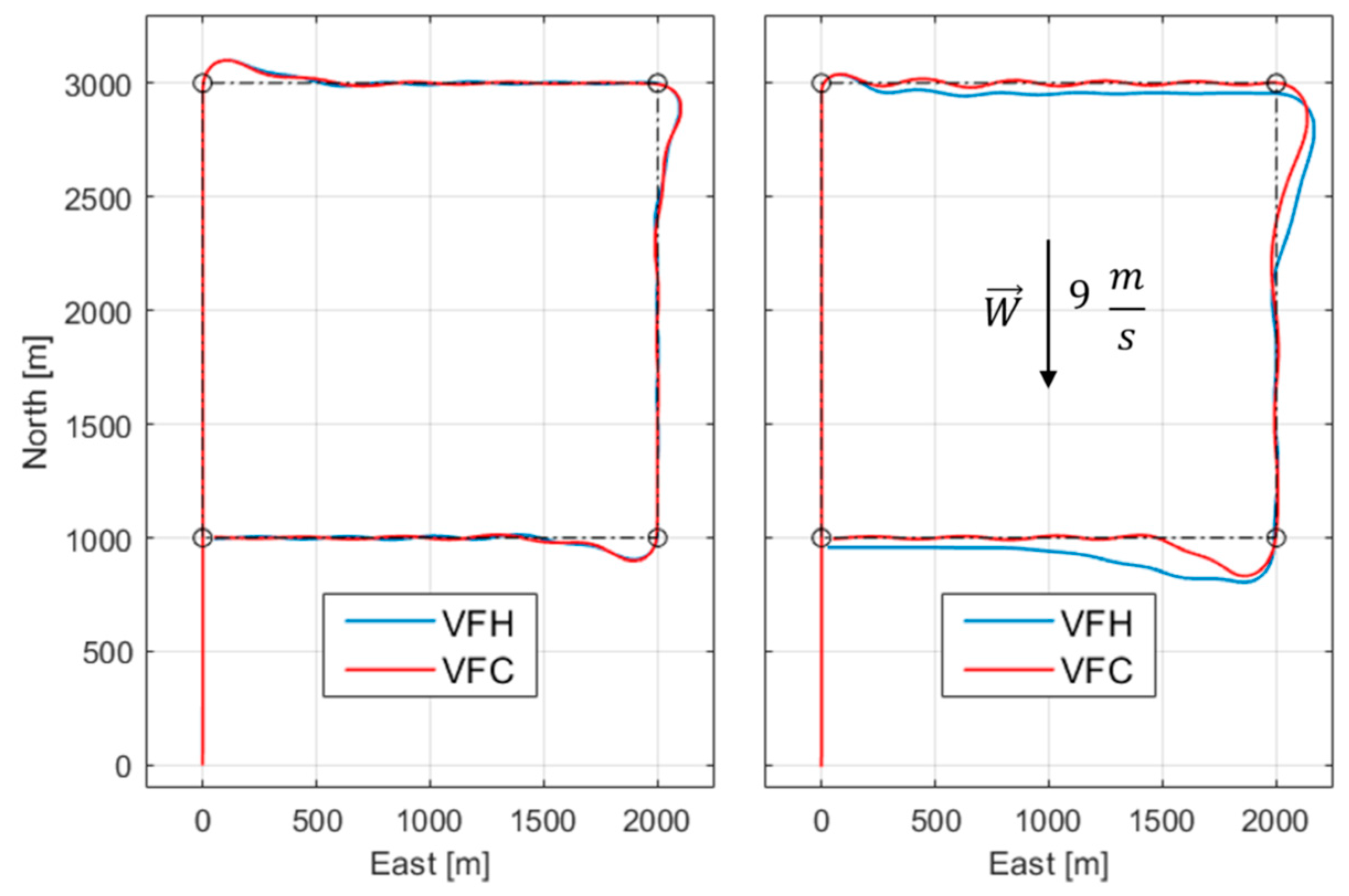
For the explanation of the results, a square route is chosen to be simulated because, by symmetry, fixing a North wind W the aircraft is impacted on all sides during flight. The maximum tolerated wind will be the one for which the UAV can reach all waypoints within a range of 50 m. The first comparison concerns the vector field VF only, which is applied to both the heading ψ and course χ angles in order to confirm the greater control effectiveness of the latter. The illustrated results are obtained with and without wind applied, with the second case wind speed equal to the maximum tolerated by both algorithms.
In
Figure 6 (a) the trajectories generated by the two algorithms are really similar since the absence of wind: the two controlled variables differ due to wind as suggested by (1); in contrast in
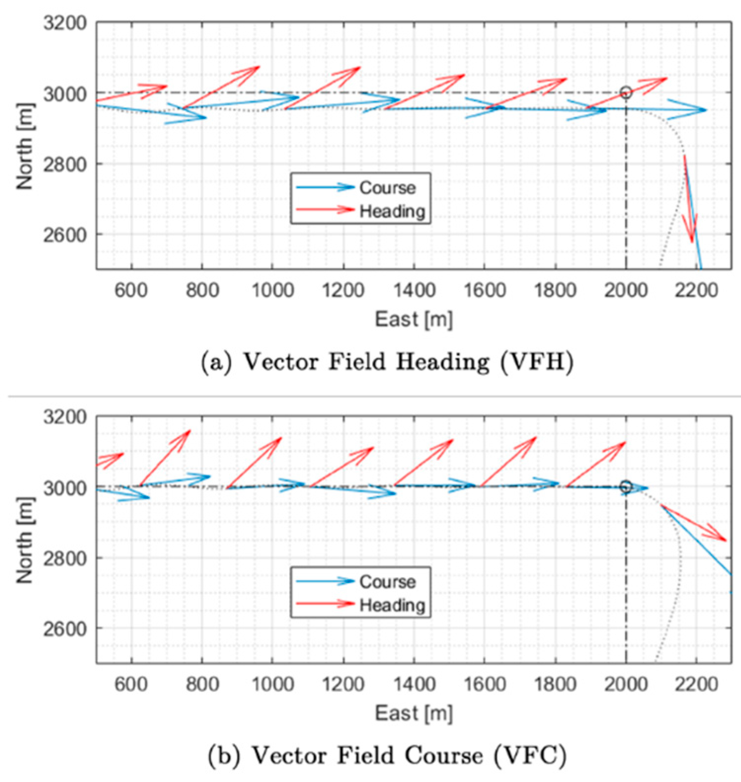
Figure 6 (b) the improvement obtained with the VFC algorithm in terms of wind tolerance is evident. The reason for this improvement can be deduced from the observation of
Figure 7, which shows how in VFC the UAV nose tends to head to the wind direction, therefore providing a more aerodynamic profile also reducing drag forces.
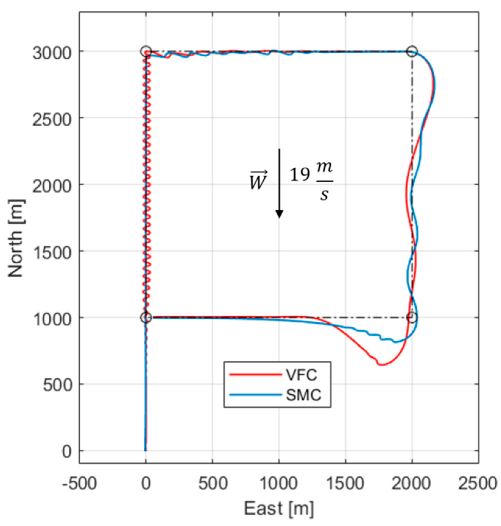
The test confirms that the course angle is the best to use as controlled quantity in the guidance law as it can handle the wind more successfully. Once the heading variable is excluded, the comparison between VFC and SMC guidance laws is reported. The SMC law is developed by a sliding mode approach to the vector field algorithm and based on the same angle χ to accomplish better results. The test scenario is like the previous one: the maximum wind tolerated by both algorithms is found and implemented in the square path.
Figure 8 illustrates the results and highlights significant parts.
In the first side of the path the behavior of the UAV controlled with the VFC is more nervous causing inefficiencies and thus increased consumption, while with the SMC such behavior is mitigated because of its upper limit and its derivative term which damps oscillations around the path. The third side is the most critical for both techniques because of the strong influence a tailwind has on the UAV aerodynamics. The area with the most pronounced divergence is the last curve, where the difference between the waypoint-switching over-elongation is evident, due to the different control effort produced by the two techniques.
A comparison of the performance according to the indices proposed above is reported.
Table 1 shows the results for
Figure 8 scenario and for the maximum wind tolerated by the SMC. Simulations prove a clear superiority of the SMC algorithm with respect to both performance and efficiency. The performance in the respective wind boundary conditions are comparable, however an increase in power consumption and mission time is noted but mainly due to the stronger wind, which requires more thrust and causes lower ground velocities. In the final analysis the two course-based algorithms are built and deployed on hardware to be run for a portability test. The adopted hardware is the MicroLabBox dSPACE® which is a high-performance dual-core platform. It results to be oversized for this purpose but also very accurate and reliable since its computational capacity. Both the guidance laws are run at 400 Hz simulating the mission scenario in
Figure 8 and turnaround times and overruns are recorded. The SMC algorithm results to be 15 % slower to be run with respect to the VFC one. The higher computational load is not enough to deny the SMC superiority in performance and efficiency.
4.1. Waypoint Transitions
As can be seen in
Figure 8 the areas around waypoints appear to be the most critical in terms of cross-track error. Path following performance are particularly affected there since the trajectory is not directly planned but the result of the transition between references of two adjacent traits. The transition technique used previously is the most commonly adopted in autopilot systems. This classical technique involves forcing the transition between one waypoint and the next when entering the predefined circle of radius rwp. The new route reference ψw is provided causing the convergence to the next trait. In spite of its simplicity the following disadvantages are identified:
no real desired path is planned within the circle so the trajectory is unpredictable;
the radius rwp of the circle must be chosen within a limited range: too large a radius will cause loss of flight accuracy while too small a radius will cause an incapacity to reach the waypoint and start the maneuver.
In order to eliminate these disadvantages different transition techniques were studied in literature[
19,
20,
21]. In this section an alternative waypoint transition method is investigated. The new technique no longer relies on the radius
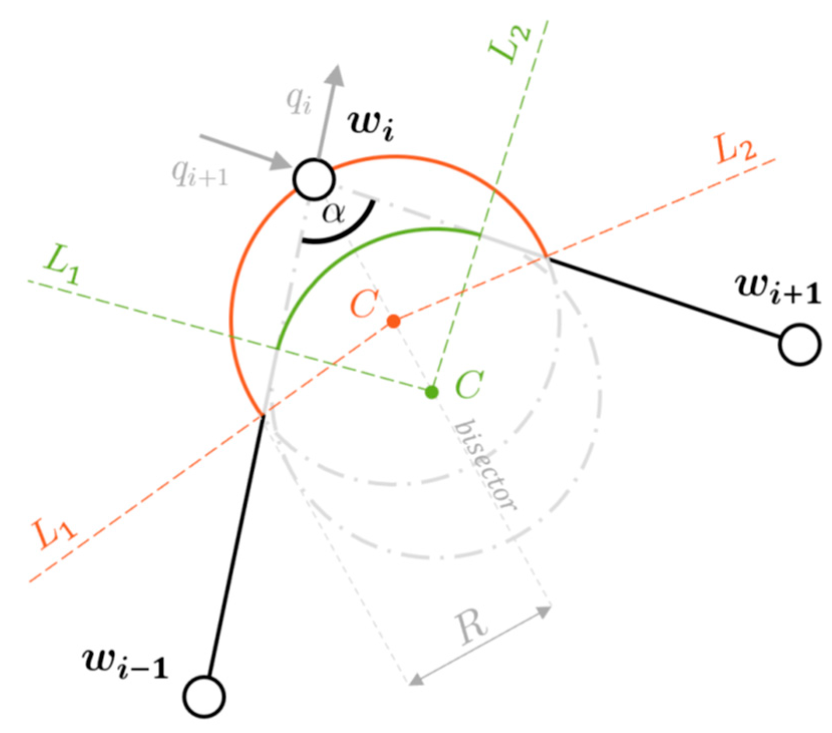
rwp but it is activated by crossing a predefined line; moreover throughout the transition a circular arc is imposed as desired flight path. The application of the introduced method requires some geometric variables, that can be deduced from the only versors of the traits to be traveled[
22]:
the angle α between the two adjacent traits of the path;
the center of the orbit C, which always lies on the bisector of the angle α;
the distance l along the path between the destination waypoint and the line L of the beginning/ending of the transition.
Figure 9 illustrates the mentioned variables in a generic transition scenario.
The new technique involves beginning and end of the transition at the crossing of the line
L1 and
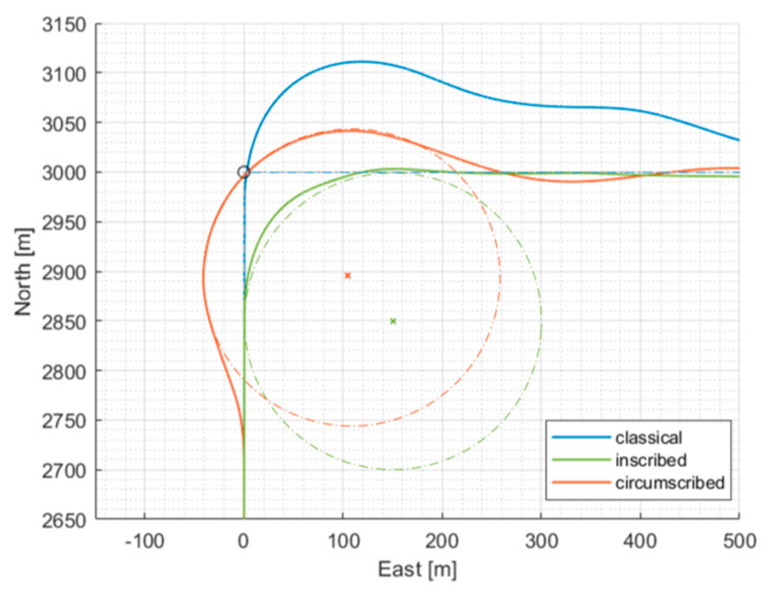
L2 respectively, and causes the UAV to travel the arc of orbit between them. On the basis of the most common path following requirements in aviation, a variation to the technique just presented is added, which differs by the imposed circle center. Both the geometries are shown in
Figure 9. Fixed the orbit radius
R, rather than inscribing the transition circle at the angle
α (green), a circumscribed trajectory passing through the destination waypoint is defined (orange). These two techniques henceforth are identified as
inscribed technique and
circumscribed technique. Similarly to the
classical technique where the reference change occurs in advance of reaching the waypoint, in both the two new transitions the orbit reference is also provided in advance respect to the
L1 line crossing: this adjustment is intended to compensate for delays related to inertia and flight dynamics. In order to better appreciate their behavior, results are shown relative to the first turn of the square scenario with no wind implemented.
Figure 10 plots both references and real trajectories for every techniques and highlights the uncontrolled overshoot of the classical technique compared to the other two.
The results shown in
Table 2 refer instead to the entire square path scenario, where for each technique the benchmarks are calculated with respect to the corresponding reference paths. As confirmed by the table the inscribed technique involves the best performance, indeed its orbit arc is always tangent to the straight traits thus facilitating remaining on the desired path. Before one transition is preferable however, it should be considered that these two techniques meet different needs:
the inscribed technique minimizes time and distance traveled by anticipating the turn and thus avoiding passing over the waypoint;
the circumscribed technique instead imposes the reaching of the waypoint but increases the desired path length and thus the associated fuel consumption consequently.
Depending on mission requirements it may be convenient to renounce better performance to ensure the proper waypoint achievement. Both the new techniques are significantly better performing than the original anyway because of a proper definition of the guidance problem and path around waypoints.
5. Conclusions
In this paper a fixed-wing path following method based on a sliding mode approach to vector field theory was developed. Due to Lyapunov theory this new guidance law ensures not only the asymptotic stability of the sliding surface but on the same principles also the convergence of the UAV to straight paths and circular orbits and the tolerance to constant wind disturbances. The obtained guidance law exploits the banking dynamics and guarantees the good helmsman behavior due to the definition of the specific vector field. Flight simulations were conducted in a highwind scenario for all the algorithms. The results show how the wind robustness of both is comparable and in the range of 80% of the airspeed (≈ 35 kn). The SMC proved however to be significantly better in terms of performance and efficiency of path following leading to the lowest average cross-track error, attested around 2.5 times the wingspan. Moreover, in terms of portability it results only 15 % slower than the VFC algorithm to be run. Finally three different transition techniques were investigated. In the critical areas around waypoints the SMC algorithm was modified to improve effectiveness over transitions, however the choice of a solution strongly depends on the requirements of the assigned mission.
Funding
This research received no external funding.
Acknowledgments
Authors wish to thank both
Conflicts of Interest
The authors declare no conflicts of interest.
References
- Sujit, P.B.; Saripalli, S.; Sousa, J.B. Unmanned aerial vehicle path following: A survey and analysis of algorithms for fixed-wing unmanned aerial vehicles. IEEE Control Systems Magazine 2014, 34, 42–59. [Google Scholar]
- Conte, G.; Duranti, S.; Merz, T. Dynamic 3D path following for an autonomous helicopter. IFAC Proceedings Volumes 2004, 37, 472–477. [Google Scholar] [CrossRef]
- Ambrosino, G.; Ariola, M.; Ciniglio, U.; Corraro, F.; De Lellis, E.; Pironti, A. Path generation and tracking in 3-D for UAVs. IEEE Transactions on Control Systems Technology 2009, 17, 980–988. [Google Scholar] [CrossRef]
- Wang, Y.; Wang, X.; Zhao, S.; Shen, L. Vector field based sliding mode control of curved path following for miniature unmanned aerial vehicles in winds. Journal of Systems Science and Complexity 2018, 31, 302–324. [Google Scholar] [CrossRef]
- Ratnoo, A.; Sujit, P.B.; Kothari, M. Adaptive optimal path following for high wind flights. IFAC Proceedings Volumes 2011, 44, 12985–12990. [Google Scholar] [CrossRef]
- Dacic, D.B.; Nesic, D.; Kokotovic, P.V. Path-following for nonlinear systems with unstable zero dynamics. IEEE Transactions on Automatic Control 2007, 52, 481–487. [Google Scholar] [CrossRef]
- Ostertag, E. An Improved Path-Following Method for Mixed H2/H∞ Controller Design. IEEE Transactions on Automatic Control 2008, 53, 1967–1971. [Google Scholar] [CrossRef]
- Nelson, D.R.; Barber, D.B.; McLain, T.W.; Beard, R.W. Vector field path following for miniature air vehicles. IEEE Transactions on Robotics 2007, 23, 519–529. [Google Scholar] [CrossRef]
- Beard, R.W.; Ferrin, J.; Humpherys, J. Fixed wing UAV path following in wind with input constraints. IEEE Transactions on Control Systems Technology 2014, 22, 2103–2117. [Google Scholar] [CrossRef]
- Coelho, P.; Nunes, U. Path-following control of mobile robots in presence of uncertainties. IEEE Transactions on Robotics 2005, 21, 252–261. [Google Scholar] [CrossRef]
- Aguiar, A.P.; Hespanha, J.P. Trajectory-tracking and path-following of underactuated autonomous vehicles with parametric modeling uncertainty. IEEE transactions on automatic control 2007, 52, 1362–1379. [Google Scholar] [CrossRef]
- Casazza, A.; Fiorenzani, R.; Mela, A.; Pugi, L.; Reatti, A. Modelling of Unmanned Aerial Vehicles with Vertical Take Off and Landing Capabilities. In International Workshop IFToMM for Sustainable Development Goals; Springer: Cham, 2021; pp. 255–263. [Google Scholar]
- Beard, R.W.; McLain, T.W. Small unmanned aircraft: Theory and practice; Princeton university press, 2012. [Google Scholar]
- Rysdyk, R. (2003) UAV path following for constant lineof-sight, In 2nd AIAA” Unmanned Unlimited” Conf. and Workshop & Exhibit (p. 6626).
- Park, S.; Deyst, J.; How, J.P. Performance and lyapunov stability of a nonlinear path following guidance method. Journal of Guidance, Control, and Dynamics 2007, 30, 1718–1728. [Google Scholar] [CrossRef]
- Machmudah, A.; Shanmugavel, M.; Parman, S.; Manan TS, A.; Dutykh, D.; Beddu, S.; Rajabi, A. Flight Trajectories Optimization of Fixed-Wing UAV by Bank-Turn Mechanism. Drones 2022, 6, 69. [Google Scholar] [CrossRef]
- Shah, M.Z.; Samar, R.; Bhatti, A.I. Guidance of air vehicles: A sliding mode approach. IEEE Transactions on Control Systems Technology 2014, 23, 231–244. [Google Scholar] [CrossRef]
- Kim, K.J.; Park, J.B.; Choi, Y.H. (2006) Chattering free sliding mode control, In 2006 SICE-ICASE international Joint conference (pp. 732-735). [CrossRef]
- Beard, R.W.; Humpherys, J. (2011) Following straight line and orbital paths with input constraints., In Proceedings of the 2011 American Control Conference (pp. 1587-1592). [CrossRef]
- Capello, E.; Guglieri, G.; Quagliotti, F.B. (2009) UAVs and simulation: an experience on MAVs, Aircraft Engineering and Aerospace Technology. [CrossRef]
- McLain, T.; Beard, R.W.; Owen, M. (2014) Implementing dubins airplane paths on fixed-wing uavs, Contributed chapter to the Handbook of Unmanned Aerial Vehicles, Springer, ch. 68, pp. 1677–1701. [CrossRef]
- Kikutis, R.; Stank¯unas, J.; Rudinskas, D. Autonomous unmanned aerial vehicle flight accuracy evaluation for three different path-tracking algorithms. Transport 2019, 34, 652–661. [Google Scholar] [CrossRef]
|
Disclaimer/Publisher’s Note: The statements, opinions and data contained in all publications are solely those of the individual author(s) and contributor(s) and not of MDPI and/or the editor(s). MDPI and/or the editor(s) disclaim responsibility for any injury to people or property resulting from any ideas, methods, instructions or products referred to in the content. |
© 2024 by the authors. Licensee MDPI, Basel, Switzerland. This article is an open access article distributed under the terms and conditions of the Creative Commons Attribution (CC BY) license (http://creativecommons.org/licenses/by/4.0/).

