1. Introduction
The photocathode gun is a high-brightness electron source capable of producing high-quality, shape-controllable electron beams. It is widely used in applications such as free-electron lasers (FELs) [
1,
2,
3,
4], energy recovery linacs (ERLs) [
5,
6], Compton scattering sources [
7,
8,
9], and ultrafast electron diffraction [
10,
11]. In a photocathode electron gun, electron beam is generated through photoelectric effect. The initial distribution of the beam is primarily determined by the profile of the photocathode drive laser and the quantum efficiency (QE) map of the photocathode. As a result, transverse laser shaping is a crucial method for controlling the transverse distribution of the electron beam.
Transverse laser shaping techniques can be categorized into passive and active shaping methods. Passive shaping methods are used to produce lasers with fixed profiles, where the effectiveness is determined by the quality of incident lasers. For example, radial birefringent filters can transform a Gaussian laser into a flat-top distribution [
12,
13], optical beam expanders combined with an aperture can generate a truncated Gaussian distribution [
14], while aspherical lenses [
15,
16] or microlens arrays (MLAs) [
17,
18] are used to create specific uniform or arrayed laser distributions. Although relying on high-quality incident laser beams, these methods are simple, convenient, cost-effective, and therefore widely used for generating fixed laser distributions. In contrast, active shaping methods offer the flexibility to generate arbitrarily shaped transverse laser distributions, tailored to the incident laser profile and specific requirements. For example, spatial light modulators (SLMs) can modulate the laser’s wavefront phase [
19,
20,
21] or polarization [
21], digital micromirror devices (DMDs) can control the reflection angle of the laser at each position [
22,
23], and deformable mirrors can adjust the laser wavefront [
24,
25], enabling the laser to evolve into a specific spatial distribution.
Transverse shaping of the photocathode drive laser has become widely utilized in accelerator-related research [
26], including applications such as electron beam emittance optimization [
27,
28,
29], beamline alignment [
30], photocathode QE map measurements [
31], and ghost imaging [
32,
33]. Over time, as a photocathode is used, its quantum efficiency (QE) distribution tends to become increasingly non-uniform [
34]. Therefore, achieving efficient real-time QE map measurements and implementing more precise laser distribution control based on the measurements are critical focuses for producing high-quality electron beams.
In this study, experiments were conducted on the DC-SRF-II photocathode gun at Peking University to investigate the control of transverse distribution of electron beams [
35,
36]. Transverse laser shaping was performed on the photocathode drive laser, referred to as the Peking University drive Laser System for high-brightness Electron source (PULSE) [
37], by utilizing an SLM in combination with polarization beam-splitting optics. GPT [
38] simulations were used to determine the optimal conditions for electron beam imaging. The results show that by adjusting the RF phase and solenoid strength in the DC-SRF-II gun, an electron beam with an intensity distribution closely matching that of the laser could be achieved. Based on electron beam imaging, a fast method for QE map measurement was proposed, and through laser distribution control, a more uniform electron beam was produced.
2. Adaptive Transverse Laser Shaping
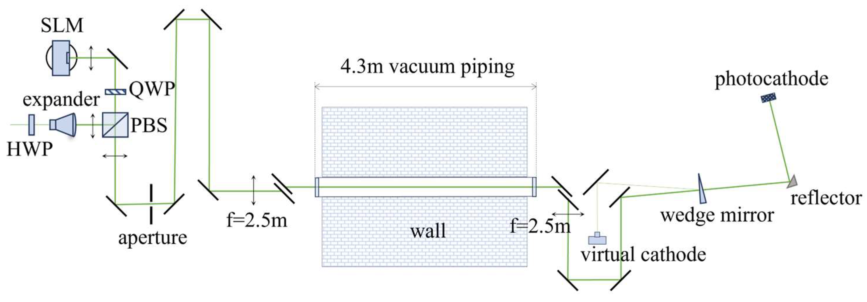
We employ a SLM to achieve arbitrary transverse shaping of the 515 nm linearly polarized laser generated by PULSE. Optical polarization elements are combined to adjust the polarization components, which enables laser field modulation. Furthermore, a feedback algorithm is utilized to enhance shaping precision. A schematic diagram of the layout for the laser shaping is presented in
Figure 1.
As shown in
Figure 1, the input laser power ratio passing through the polarization beam splitter (PBS) is adjusted using a half-wave plate (HWP), and then the p-polarization is converted to circular polarization using a quarter-wave plate (QWP). Subsequently, the laser is modulated by the liquid crystal pixels of the SLM. When the phase of the liquid crystal pixels loaded on the SLM is
φ=0, the laser is entirely reflected to the target plane. Conversely, when the phase of these pixels is adjusted to
φ=π, no laser output from the SLM reaches the target plane. Furthermore, when adjusting the change of phase for pixel
on the SLM, notated as
, within a range between 0 and π, the output laser intensity on the target plane can be described by
where
represents the position on the target plane corresponding to the pixel
. In the practical optical configuration, the laser distribution between the target plane and the SLM plane does not directly correspond due to factors such as the position and angle of optical elements, pixel ratios, and imaging relationships. Consequently, translation, scaling, and rotation occur between
and
.
Typically, errors arise from factors such as phase and reflectance errors on SLM, measurement errors in the incident laser distribution, and spurious reflections from PBS. They may result in discrepancies between the shaping results and the target distribution. To further reduce this deviation, an automatic feedback optimization algorithm is designed. The algorithm compares the actual measured laser field amplitude on the CCD () with the final target laser field amplitude (), and then adjusts the laser field amplitude on the SLM (A) based on the deviation between and .
According to the laser field
A, the new phase of liquid crystal pixel on SLM can be calculated using Equation (1) to optimize the shaping output. The shaping is iterated until an appropriate laser field distribution on the target plane is attained. The feedback process can be expressed as
where
is the laser field distribution measured by the CCD in the
k-th iteration,
is the laser field input to the SLM in the
k-th iteration,
is the laser field obtained in the (
k+1)-th iteration,
serves as a reference target and remains constant throughout the feedback process, while
H is a normal constant coefficient. In our experiments,
H is set to 1 so as to adjust the feedback and prevent the calculated laser field
A from exceeding the incident laser field.
To quantitatively evaluate the difference between the intensity distribution of the shaped laser and the target, a root mean square (RMS) deviation for transverse shaping is defined as
where
is the target intensity (normalized),
is the measured intensity (normalized), and
N represents the number of non-zero matrix elements of the target distribution.
The incident laser beam first passes through an achromatic zoom beam expander (Thorlabs ZBE3A, 2-8X) for expansion, and is then shaped using a Hamamatsu SLM (X13138-04WL, 1272×1024 pixels) with a pixel size of 12.5 μm. The shaped beam is finally captured by a CCD camera (Thorlabs BC106N-VIS/M, 1024×1360 pixels), which has a pixel size of 6.45 μm. To minimize the impact of dead pixels on subsequent measurements and shaping, all images were processed using median filtering. For high-brightness operation of the DC-SRF-II gun, it is required to generate circular laser spots with a flat-to distribution. A 2 mm diameter laser spot was therefore produced through shaping.
Figure 2 shows the intensity distribution of the incident laser, the initial shaping result, and the iteration result. In this case the RMS deviation is reduced from 7.8% to 3.3% via the feedback algorithm, showing a significant improvement of the output laser quality.
3. System Development
The shaped laser traverses a 4.3-meter-long vacuum tube connecting the laser room and the accelerator hall. A 4F design is employed to image the shaped laser profile from the aperture shown in
Figure 3 to the photocathode. To enable real-time monitoring of the laser spot distribution on the cathode surface, a set of virtual cathode optics was set up for observation.
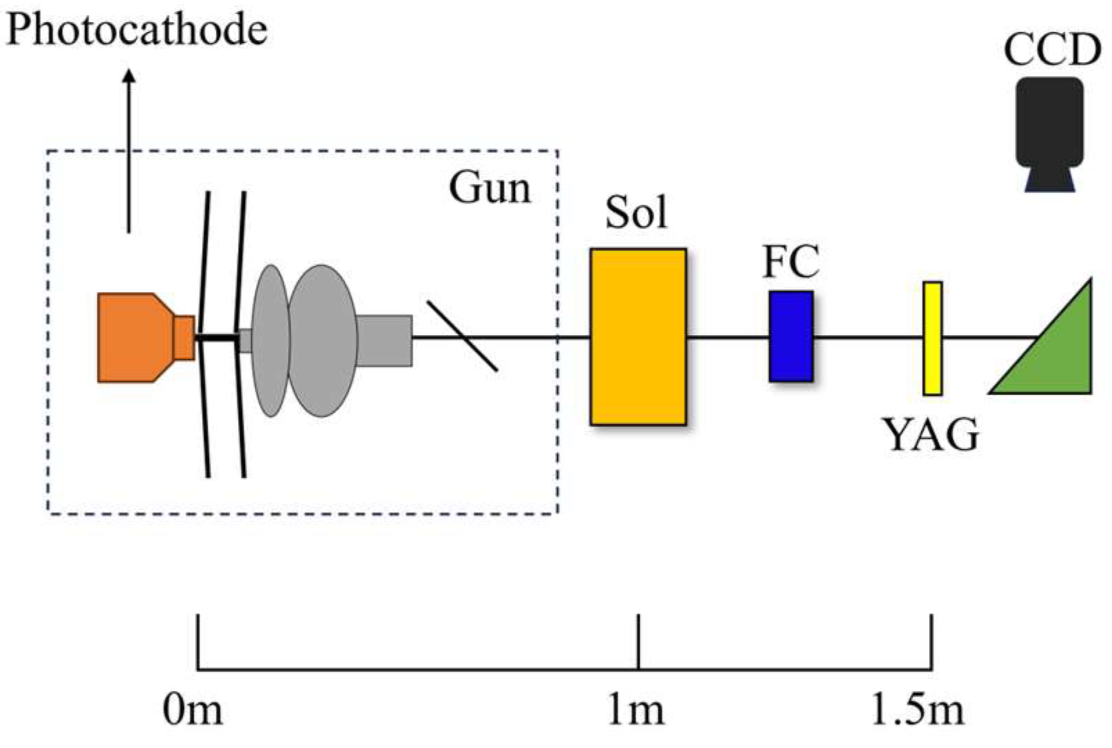
The electron beam emitted from the photocathode is accelerated by the DC-SRF-II gun and then focused by a solenoid, as illustrated in
Figure 4. The bunch charge of the electron beam is measured by a Faraday cup before being transmitted to a YAG screen positioned 1.5 meters downstream from the photocathode. The transverse distribution of the beam is then recorded using a CCD camera.
To investigate the imaging conditions for the electrons on the photocathode, the particle trajectories along the DC-SRF-II beamline were simulated using GPT. In the simulation, four electrons with different initial transverse momenta were generated from a point 1 mm off-center on the photocathode surface, as shown in
Figure 5(a). The electron momenta were normalized as
, where
m0 is the rest mass of electron and
c is the speed of light in vacuum. Primary analysis was first conducted at the phase for maximum energy gain (defined as
in the following). At 1.5 m downstream from the photocathode surface, the x and y positions of the four electrons vary with the changes of the solenoid strength, as illustrated in
Figure 5(b) and
Figure 5(c), respectively. Given specific solenoid strength at 617 Gs, the four electrons converge at a same location on the imaging plane after traveling a certain distance, indicating the imaging of the electron beam therein.
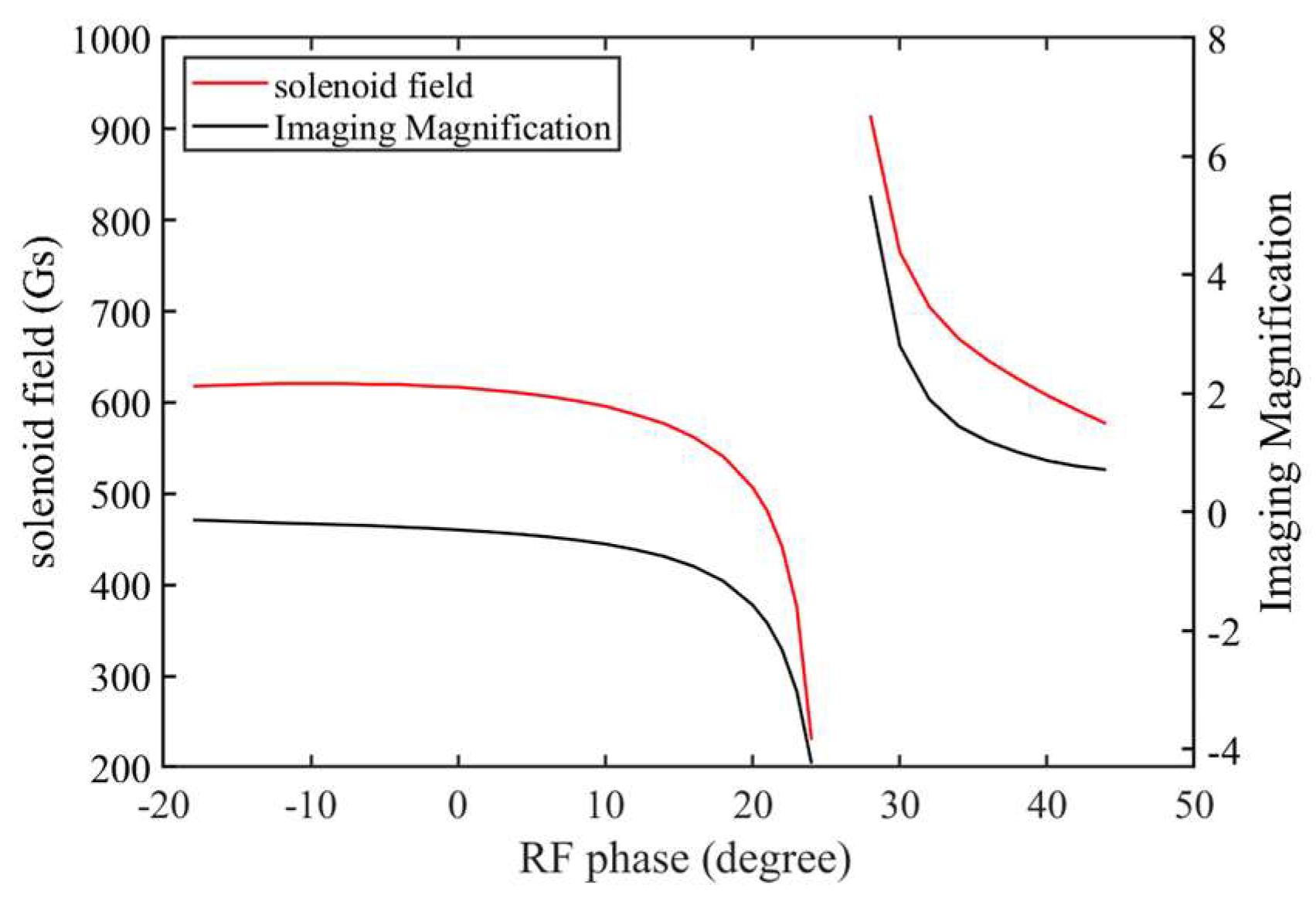
Systematic analysis was then performed to optimize the imaging conditions by scanning the RF phase of the DC-SRF gun and the solenoid strength, as shown in
Figure 6. Note that the transverse beam profile under imaging conditions has been rotated to eliminate the solenoid's rotational effect on the electron beam. When the RF phase is below 26°, an inverted image of the electron beam can be formed at 1.5 meters downstream from the photocathode with proper solenoid strength, while for phases greater than 30°, an upright image can be formed. As a compromise between the magnification factor and the required solenoid strength, our experiments were performed at an RF phase of 20°.
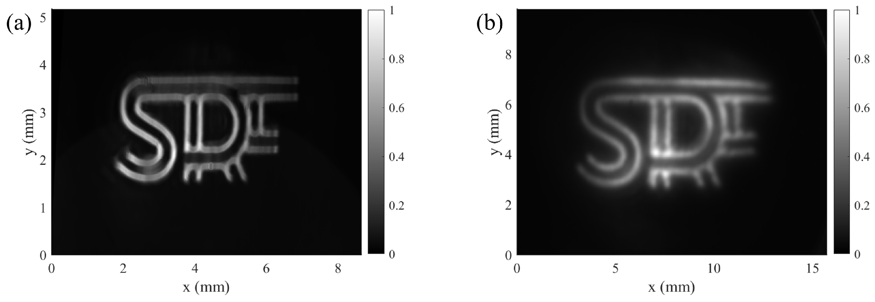
Figure 7 shows a test of the electron beam imaging using a shaped laser as illustrated in
Figure 7(a), where the solenoid strength was set to 504 Gs. The resulting electron beam profile measured on the YAG screen is shown in
Figure 7(b), which closely matches the shaped laser profile. This demonstrates an effective manipulation of the transverse beam profile by laser shaping.
4. QE Measurement and Compensation
To produce electron beams with specific distributions through laser shaping, a precise and accurate QE map measurement is critical. QE map is typically measured by scanning the photocathode with a small laser spot [
39]. However, its precision is limited by the diffraction limit for the laser spot and the mechanical backlash in the scanning. Additionally, the scanning process is time-consuming and its accuracy can be affected by laser pointing instability and power fluctuations. In contrast, using electron beam imaging for single-shot QE map measurement can mitigate these limitations.
Under high-fidelity electron beam imaging conditions, the initial electrons emitted from the photocathode can be inferred from the measured image downstream. By comparing the distributions of the electrons and laser beam on the photocathode, the QE map can be derived. Here we present the experiment on a photocathode after extended use. In the experiment, we performed five measurements for the QE map of the central region (the active area) of the photocathode using different laser profiles. An average of the measured QE maps is shown in
Figure 8, while the uncertainty is evaluated to be 7.8%. As an comparison, SLAC reported an uncertainty of 10% in their QE measurement employing a small spot scanning in 2017 [
31]. Apparently, this single-shot electron beam imaging method offers a fast and efficient way to obtain QE map.
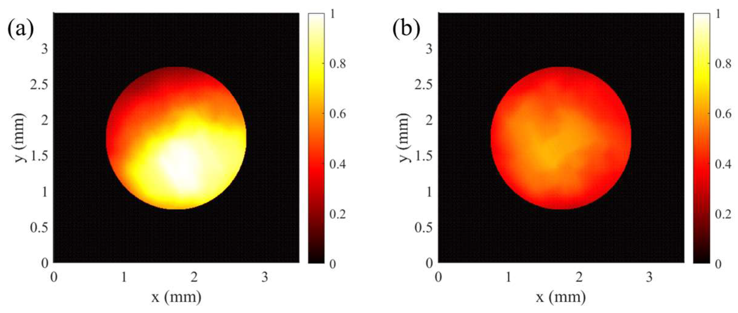
Based on the single-shot QE map measurement result, we utilized the adaptive transverse laser shaping to conduct QE compensation for a 2 mm (diameter) circular region within the lower part of
Figure 8. As shown in
Figure 9, the RMS variation of the electron density was 30.8% before compensation and decreased to 14.4% after compensation. This demonstrates a substantial enhancement in the beam uniformity, effectively mitigating the impact of non-uniform QE.
5. Conclusions
We have demonstrated the utilization of adaptive transverse laser shaping to improve the transverse electron beam distribution in a photocathode gun. By employing an SLM and the feedback algorithm, precise control over the laser distribution has been achieved, which enables the implementation of single-shot QE map measurement and QE compensation. The single-shot QE map measurement offers a rapid and efficient alternative to scanning methods and shows an improved measurement accuracy. The QE compensation, significantly reducing the RMS fluctuation of electron beam distribution, highlights the effectiveness of this shaping technique mitigating non-uniformities in photocathode QE. This work provides an efficient solution for generating high-quality electron beams with specific distributions, particularly suited for high-brightness applications.
Author Contributions
Conceptualization, Z.L. and S.H.; methodology, Z.L., H.J., H.X., J.X. and S.H.; software, Z.L. and H.J.; validation, Z.L. and J.X.; formal analysis, Z.L., H.J. and H.X.; investigation, Z.L., H.J. and H.X.; resources, J.X. and S.H.; data curation, Z.L.; writing—original draft preparation, Z.L.; writing—review and editing, H.X. and S.H.; supervision, J.X. and S.H.; project administration, S.H.; funding acquisition, S.H. All authors have read and agreed to the published version of the manuscript.
Funding
This research was funded by the National Key Research and Development Program of China (Grant No. 2017YFA0701001) and the State Key Laboratory of Nuclear Physics and Technology, Peking University (Grant No. NPT2022ZZ01).
Institutional Review Board Statement
Not applicable.
Informed Consent Statement
Not applicable.
Data Availability Statement
The data presented in this study will be made available by the authors on request.
Conflicts of Interest
The authors declare no conflicts of interest.
References
- Emma, P.; Akre, R.; Arthur, J.; Bionta, R.; Bostedt, C.; Bozek, J.; Brachmann, A.; Bucksbaum, P.; Coffee, R.; Decker, F.J.; et al. First lasing and operation of an ångstrom-wavelength free-electron laser. Nat. Photonics 2010, 4, 641–647. [Google Scholar] [CrossRef]
- Kang, H.-S.; Min, C.-K.; Heo, H.; Kim, C.; Yang, H.; Kim, G.; Nam, I.; Baek, S.Y.; Choi, H.-J.; Mun, G.; et al. Hard X-ray free-electron laser with femtosecond-scale timing jitter. Nat. Photonics 2017, 11, 708–713. [Google Scholar] [CrossRef]
- Decking, W.; Abeghyan, S.; Abramian, P.; Abramsky, A.; Aguirre, A.; Albrecht, C.; Alou, P.; Altarelli, M.; Altmann, P.; Amyan, K.; et al. A MHz-repetition-rate hard X-ray free-electron laser driven by a superconducting linear accelerator. Nat. Photonics 2020, 14, 391–397. [Google Scholar] [CrossRef]
- Pellegrini, C. The development of XFELs. Nat. Rev. Phys. 2020, 2, 330–331. [Google Scholar] [CrossRef]
- Huang, S.; Liu, K. Energy recovery linac light source. High Power Laser and Particle Beams 2022, 34, 104011. [Google Scholar]
- Neil, G.R.; Behre, C.; Benson, S.V.; Bevins, M.; Biallas, G.; Boyce, J.; Coleman, J.; Dillon-Townes, L.A.; Douglas, D.; Dylla, H.F.; et al. The JLab high power ERL light source. Nucl. Instrum. Methods Phys. Res. A 2006, 557, 9–15. [Google Scholar] [CrossRef]
- Hartemann, F.V.; Brown, W.J.; Gibson, D.J.; Anderson, S.G.; Tremaine, A.M.; Springer, P.T.; Wootton, A.J.; Hartouni, E.P.; Barty, C.P.J. High-energy scaling of Compton scattering light sources. Phys. Rev. ST Accel. Beams 2005, 8, 100702. [Google Scholar] [CrossRef]
- Gibson, D.J.; Albert, F.; Anderson, S.G.; Betts, S.M.; Messerly, M.J.; Phan, H.H.; Semenov, V.A.; Shverdin, M.Y.; Tremaine, A.M.; Hartemann, F.V.; et al. Design and operation of a tunable MeV-level Compton-scattering-based γ-ray source. Phys. Rev. ST Accel. Beams 2010, 13, 070703. [Google Scholar] [CrossRef]
- Deitrick, K.E.; Krafft, G.A.; Terzić, B.; Delayen, J.R. High-brilliance, high-flux compact inverse Compton light source. Phys. Rev. Accel. Beams 2018, 21, 080703. [Google Scholar] [CrossRef]
- Weathersby, S.P.; Brown, G.; Centurion, M.; Chase, T.F.; Coffee, R.; Corbett, J.; Eichner, J.P.; Frisch, J.C.; Fry, A.R.; Gühr, M.; et al. Mega-electron-volt ultrafast electron diffraction at SLAC National Accelerator Laboratory. Rev. Sci. Instrum. 2015, 86. [Google Scholar] [CrossRef]
- Wu, J.; Tang, M.; Zhao, L.; Zhu, P.; Jiang, T.; Zou, X.; Hong, L.; Luo, S.-N.; Xiang, D.; Zhang, J. Ultrafast atomic view of laser-induced melting and breathing motion of metallic liquid clusters with MeV ultrafast electron diffraction. Proc. Natl. Acad. Sci. U. S. A. 2022, 119, e2111949119. [Google Scholar] [CrossRef] [PubMed]
- Eggleston, J.M.; Giuliani, G.; Byer, R.L. Radial intensity filters using radial birefringent elements. J. Opt. Soc. Am. 1981, 71, 1264–1272. [Google Scholar] [CrossRef]
- Yun, M.; Liu, L.; Sun, J.; Yan, A.; Zhou, Y. Transformation of Gaussian to uniform or annular beams by a radial birefringent filter. In Proc. SPIE 5525, Laser Beam Shaping V, Denver, Colorado, United States, 29 September 2004.
- Sannibale, F.; Filippetto, D.; Qian, H.; Mitchell, C.; Zhou, F.; Vecchione, T.; Li, R.K.; Gierman, S.; Schmerge, J. High-brightness beam tests of the very high frequency gun at the Advanced Photo-injector EXperiment test facility at the Lawrence Berkeley National Laboratory. Rev. Sci. Instrum. 2019, 90. [Google Scholar] [CrossRef] [PubMed]
- Laskin, A.; Laskin, V.; Ostrun, A. Refractive beam shapers for optical systems of lasers. In Proc. SPIE 9346, Components and Packaging for Laser Systems, San Francisco, California, United States, 20 February 2015.
- Hoffnagle, J.A.; Jefferson, C.M. Design and performance of a refractive optical system that converts a Gaussian to a flattop beam. Appl. Opt. 2000, 39, 5488–5499. [Google Scholar] [CrossRef] [PubMed]
- Schreiber, P.; Kudaev, S.; Dannberg, P.; Zeitner, U. Homogeneous LED-illumination using microlens arrays. In Proc. SPIE 5942, Nonimaging Optics and Efficient Illumination Systems II, San Diego, California, United States, 20 August 2005.
- de Oliveira, O.G.; de Lima Monteiro, D.W. Optimization of the Hartmann–Shack microlens array. Opt. Lasers Eng. 2011, 49, 521–525. [Google Scholar] [CrossRef]
- Shao, J.; Haase, T.; Zhang, R.; Aguergaray, C.; Broderick, N.; Sun, S. Focusing flattop beam shaping with complex modulation holography. AIP Adv. 2021, 11. [Google Scholar] [CrossRef]
- Alsaka, D.Y.; Arpali, Ç.; Arpali, S.A.; Altemimi, M.F. Dynamic flat-topped laser beam shaping method using mixed region amplitude freedom algorithm. Appl. Phys. B 2022, 128, 137. [Google Scholar] [CrossRef]
- Maxson, J.M.; Bartnik, A.C.; Bazarov, I.V. Efficient and accurate laser shaping with liquid crystal spatial light modulators. Appl. Phys. Lett. 2014, 105. [Google Scholar] [CrossRef]
- Ding, X.; Ren, Y.; Lu, R. Shaping super-Gaussian beam through digital micro-mirror device. SCI CHINA PHYS MECH 2015, 58, 1–6. [Google Scholar] [CrossRef]
- Liang, J.; Kohn, J.R.N.; Becker, M.F.; Heinzen, D.J. High-precision laser beam shaping using a binary-amplitude spatial light modulator. Appl. Opt. 2010, 49, 1323–1330. [Google Scholar] [CrossRef]
- Eichenberger, M.; Giorgianni, F.; Sauerwein, N.; Vicario, C.; Hauri, C.P. Deformable mirror for wavefront shaping of infrared radiation. Opt. Lett. 2018, 43, 2062–2065. [Google Scholar] [CrossRef] [PubMed]
- Matsui, F.; Goriki, S.i.; Shimizu, Y.; Tomizawa, H.; Kawato, S.; Kobayashi, T. Genetic-algorithm-based method to optimize spatial profile utilizing characteristics of electrostatic actuator deformable mirror. Opt. Rev. 2008, 15, 156–161. [Google Scholar] [CrossRef]
- Maxson, J.; Lee, H.; Bartnik, A.C.; Kiefer, J.; Bazarov, I. Adaptive electron beam shaping using a photoemission gun and spatial light modulator. Phys. Rev. ST Accel. Beams 2015, 18, 023401. [Google Scholar] [CrossRef]
- Luiten, O.J.; van der Geer, S.B.; de Loos, M.J.; Kiewiet, F.B.; van der Wiel, M.J. How to Realize Uniform Three-Dimensional Ellipsoidal Electron Bunches. Phys. Rev. Lett. 2004, 93, 094802. [Google Scholar] [CrossRef] [PubMed]
- Limborg-Deprey, C.; Bolton, P.R. Optimum electron distributions for space charge dominated beams in photoinjectors. Nucl. Instrum. Methods Phys. Res. A 2006, 557, 106–116. [Google Scholar] [CrossRef]
- Halavanau, A.; Qiang, G.; Ha, G.; Wisniewski, E.; Piot, P.; Power, J.G.; Gai, W. Spatial control of photoemitted electron beams using a microlens-array transverse-shaping technique. Phys. Rev. Accel. Beams 2017, 20, 103404. [Google Scholar] [CrossRef]
- Gulliford, C.; Bartnik, A.; Bazarov, I.; Cultrera, L.; Dobbins, J.; Dunham, B.; Gonzalez, F.; Karkare, S.; Lee, H.; Li, H.; et al. Demonstration of low emittance in the Cornell energy recovery linac injector prototype. Phys. Rev. ST Accel. Beams 2013, 16, 073401. [Google Scholar] [CrossRef]
- Li, S.; Alverson, S.; Bohler, D.; Egger, A.; Fry, A.; Gilevich, S.; Huang, Z.; Miahnahri, A.; Ratner, D.; Robinson, J.; et al. Ultraviolet laser transverse profile shaping for improving x-ray free electron laser performance. Phys. Rev. Accel. Beams 2017, 20, 080704. [Google Scholar] [CrossRef]
- Li, S.; Cropp, F.; Kabra, K.; Lane, T.J.; Wetzstein, G.; Musumeci, P.; Ratner, D. Electron Ghost Imaging. Phys. Rev. Lett. 2018, 121, 114801. [Google Scholar] [CrossRef]
- Kabra, K.; Li, S.; Cropp, F.; Lane, T.J.; Musumeci, P.; Ratner, D. Mapping photocathode quantum efficiency with ghost imaging. Phys. Rev. Accel. Beams 2020, 23, 022803. [Google Scholar] [CrossRef]
- Wang, E.; Litvinenko, V.N.; Pinayev, I.; Gaowei, M.; Skaritka, J.; Belomestnykh, S.; Ben-Zvi, I.; Brutus, J.C.; Jing, Y.; Biswas, J.; et al. Long lifetime of bialkali photocathodes operating in high gradient superconducting radio frequency gun. Sci. Rep. 2021, 11, 4477. [Google Scholar] [CrossRef] [PubMed]
- Zhao, S.; Huang, S.; Lin, L.; Liu, Y.; Jia, H.; Qin, W.; Quan, S.; Liu, K. Longitudinal phase space improvement of a continuous-wave photoinjector toward X-ray free-electron laser application. Nucl. Instrum. Methods Phys. Res. A 2021, 1018, 165796. [Google Scholar] [CrossRef]
- Jia, H.; Li, T.; Wang, T.; Zhao, Y.; Zhang, X.; Xu, H.; Liu, Z.; Liu, J.; Lin, L.; Xie, H.; et al. High-brightness megahertz-rate beam from a direct-current and superconducting radio-frequency combined photocathode gun. Phys. Rev. Res. 2024, accepted. [Google Scholar]
- Wang, T.; Xu, H.; Liu, Z.; Zhang, X.; Liu, J.; Xu, J.; Feng, L.; Li, J.; Liu, K.; Huang, S. Advanced drive laser system for a high-brightness continuous-wave photocathode electron gun. Opt. Express 2024, 32, 9699–9709. [Google Scholar] [CrossRef]
- General Particle Tracer, http://www.pulsar.nl/gpt/.
- Mammei, R.R.; Suleiman, R.; Feingold, J.; Adderley, P.A.; Clark, J.; Covert, S.; Grames, J.; Hansknecht, J.; Machie, D.; Poelker, M.; et al. Charge lifetime measurements at high average current using a K2CsSb photocathode inside a dc high voltage photogun. Phys. Rev. ST Accel. Beams 2013, 16, 033401. [Google Scholar] [CrossRef]
|
Disclaimer/Publisher’s Note: The statements, opinions and data contained in all publications are solely those of the individual author(s) and contributor(s) and not of MDPI and/or the editor(s). MDPI and/or the editor(s) disclaim responsibility for any injury to people or property resulting from any ideas, methods, instructions or products referred to in the content. |
© 2024 by the authors. Licensee MDPI, Basel, Switzerland. This article is an open access article distributed under the terms and conditions of the Creative Commons Attribution (CC BY) license (http://creativecommons.org/licenses/by/4.0/).


