Submitted:
05 November 2024
Posted:
06 November 2024
You are already at the latest version
Abstract
The search for higher energy efficiency of industrial-scale burners to attain low emission especially Nitrogen Oxide (NOx) has demanded experimental studies that are complemented with Computational Fluid Dynamics (CFD) simulations. While there exist numerous emission control techniques, the passive control technique was the main focus of the present review study. Biodiesel fuel crude palm oil (CPO) was found to reduce emission components, particularly carbon components and particulate matter (PM). Biodiesel CPO has the capability to mitigate cavitation inside the injector’s orifice which contributes to damage reduction on the orifice. Moreover, although cavitation can improve spray atomization and produce finer spray droplets, it also causes damage to the orifice of injectors. Orifice characteristics such as orifice’s diameter and pattern can also reduce cavitation inside the orifice. Orifice’s pattern is divided into cylindrical shape orifice and conical shape orifice. The conical orifice is found to reduce the cavitation inside the orifice while cylindrical orifice was indicated as a highly cavitating orifice. Alternatively, as rapid swirling motion is capable to enhance the fuel and air mixing, a new concept of swirling fuel-air premix inside the injector is invented and it is proven to reduce emissions. It was, however, learned that spray characteristics are still playing an important role in the prediction of combustion performance, particularly droplets Sauter Mean Diameter (SMD) which is a worldwide parameter that needs further investigations in order to predict the fineness of spray production and combustion.
Keywords:
CFD
; biodiesel CPO
; premix injector
; fuel-air mixing
; swirling effects
; orifice characteristics
; spray behaviour
1. Introduction
The global environmental effects have become prominent issues that draw the interest of researchers at a global level [1]. In order to face these new challenges in the coming years, efforts to reduce harmful gases by improving the burner system needs to be prioritized [2,3]. Governments and organizations from almost all over the world are working hard to protect the environment by establishing stringent legislation and regulations for controlling the emissions particularly Nitrogen Oxide (NOx) [4]–[7]. This patented burner system boasts high efficiency, employing a specially designed oil burner to achieve ultra-efficient combustion, thereby minimizing oil consumption and reducing greenhouse gases and other harmful emissions. Improving the energy efficiency of industrial-scale burners to achieve low emissions, especially Nitrogen Oxide (NOx), requires experimental research supported by Computational Fluid Dynamics (CFD) simulations [8]. Various strategies have been created over the years to curb emissions. These methods of emission control are classified into two primary categories: active and passive control methods. Active control techniques modify flame characteristics through external influences on the combustion system, such as acoustic forcing or magnetic fields. Conversely, passive control methods adjust flame dynamics by altering initial conditions like fuel selection, varying fuel and oxidizer proportions, or changing burner geometry [9]. Thus, this review primarily explores passive control techniques, examining the impacts of varying fuel properties and specific modifications made to the premix injector.
1.1. Biodiesel as an Alternative Fuel
The global rise in population and excessive fossil fuel consumption are significant concerns today. Technological advancements have resulted in an increased reliance on hydrocarbon fuels [10]. As a result, there's a pressing need to find alternative oils to either replace or lessen the reliance on hydrocarbon fuels [11]. The rise in oil prices and the need to minimize greenhouse gas emissions are driving global advancements in renewable energy sources. The energy security and environmental issues have been a concern for researchers, particularly in biologically derived alternative fuels. Biodiesel, a renewable fuel, is derived from esters of vegetable oils and animal fats [11,12]. Biodiesel offers a superior combustion emission profile, emitting lower levels of particulate matter, unburned hydrocarbons, and carbon monoxide (CO) than petroleum-based diesel. The carbon dioxide generated from burning biodiesel is recycled through photosynthesis, helping to mitigate its impact on the greenhouse effect [13,14,15]. Moreover, biodiesel also acts as a lucrative alternative fuel which is particularly used in burner system, compression ignition engines and gas turbines. It is a renewable energy source that has similar properties to petroleum diesel fuel which can be used without the need for significant changes in their design [4]. It is basically a mixture of few organic molecules with high molecular mass which has higher density and viscosity than petroleum diesel. However, the properties of evaporation and cavitation of biodiesel are quite different compared to diesel [5]. Nevertheless, its benefits in terms of fuel economy and environmental impact are well acknowledged [5]. Biodiesel can also be produced from various biomasses, while most of it is produced through the process of transesterification. The usage of biodiesel also contributes to the reduction of unwanted emissions such as particulate matter (PM) and unburnt hydrocarbons [4,5]. However, it increases NOx emissions which is still an issue for researchers in the field [5]. This is because, the NOx produced from the combustion causes many unfavourable environmental influences including ozone hole, photochemical smog and acid rain [6].
1.2. Spray Combustion and Its Key Contribution
Understanding the fundamental and phenomena of spray formation and atomization are motivated to achieve better performances, emissions reduction and prolong the lifetime of the furnace and burner [16]. Sprays are created when the interface between a liquid and a gas deforms, resulting in the formation of liquid droplets [17]. They shift out and then enter the body of the gas, as the gas gives a negligible impact on the dynamics and kinematics of the droplets formation process. However, there are few spray characteristics for combustion performance that are always investigated such as mean droplet size, droplet size distribution, patternation, cone angle and penetration. The mean droplet size, droplet size distribution and patternation mostly depend on the design of the atomizer used. Meanwhile, the cone angle and penetration are partially dependent on the atomizer design and on the aerodynamic influences [18,19].
Spray combustion is commonly used in the process of industries for the purpose of gaining energy and power. Nowadays, the popularity of effervescent atomizers for combustion purposes is increasing. Lefebvre and his colleagues were the first researchers to introduce those atomizers in the late 1980s [16]. However, spray formation and atomization process are greatly dependent on the nozzle design [4,5]. This is because nozzle geometry of a burner plays a significant role in flow characteristics, atomization and formation of the fuel-air mixture while improving combustion performance and reducing pollutant products [2,20,21].
Numerous analysis and investigations pertaining to combustion and emissions have been performed in the burner system experimentally and numerically all over the world. However, the current extensive literature review found that detailed studies on the characteristics of spray atomization of nozzle geometry in a burner are less frequent. Only a few studies are available concerning the spray characteristics of biodiesel fuel. Moreover, the numerical simulation studies available on the influences of nozzle characteristics on spray behaviour in the burner are relatively less compared to studies in the internal combustion engine.
Ing et al. [18] performed a numerical study on the spray characteristics of a blend of biofuels with diesel and commercial diesel fuel (CDF) in a gas turbine. It was highlighted that the blends of biodiesel with diesel have larger estimated diameters compared to diesel fuel. This occurs because its fuel properties influence spray formation. Moreover, its higher viscosity compared to diesel fuel results in unstable sprays and droplets. Furthermore, they also predicted that when the fuel viscosity increases, the Sauter mean diameter (SMD) also increases. Therefore, diesel fuel produces the smallest SMD than other blends of biodiesel. Similarly, Suh et al. [22], performed an experimental analysis examining the flow characteristics within a scaled-up nozzle for petrodiesel and biodiesel. Their findings indicated that biodiesel had a lower injection velocity and mass flow rate compared to diesel, attributed to its higher viscosity.
Benajes et al. [23] studied experimentally on how conical and cylindrical nozzle orifices impact injection rate behaviour under steady-state conditions using a cavitation test rig. The study revealed that a conical orifice reduces cavitation, and improves flow efficiency (discharge coefficient) and exit velocity, in comparison to a cylindrical orifice. Payri et al. [24] investigated the impact of cavitation on diesel spray behavior, noting that the mass flow rate of a conical nozzle correlated with the pressure drop, provided there was no cavitation at the nozzle exit. Meanwhile, the cylindrical nozzle was in smothery conditions. Furthermore, the injection velocity for cylindrical nozzle risen, due to the existence of the vapor at the orifice exit. However, Han et al. [25] noted that nozzle geometry significantly affects the primary breakup region when comparing conical and cylindrical nozzles.
Som et al. [26] studied both numerical and experimental studies on the impact of hole shape and hydrogrinding on biodiesel sprays. They found that conical nozzle shapes significantly decrease cavitation and turbulence levels within the orifice. Additionally, they pointed out that conical shapes could delay the primary breakup process, resulting in larger spray droplets, increased penetration, and a wider cone angle. Moreover, Som et al. [4] also performed a numerical study to quantify the differences between biodiesel and diesel flow through the inner nozzle flow dynamics. It was observed that biodiesel was less cavitating than petrodiesel. Biodiesel's higher viscosity led to decreased flow efficiency and injection velocity. Additionally, the turbulence levels at the nozzle's orifice exit were lower for biodiesel. However, it was noticed that the spray penetration was marginally higher for biodiesel compared to petrodiesel. The cone angle also was relatively lower. It could be concluded that these criteria attributed to its poor atomization characteristics.
Similarly, Battistoni et al. [5] conducted simulations comparing diesel and biodiesel. They found that both fuels exhibited similar outlet values for mass flow rate, velocity, turbulent kinetic energy, and volume fraction when using a cylindrical (cavitating) hole. However, diesel performed slightly better with a conical nozzle. The concurrent phenomena of higher density leading to higher mass flow was seen as an advantage for biodiesel. Moreover, the lower viscosity caused an increase in the discharge coefficient and exit velocity at the nozzle outlet which is an advantage for diesel. Furthermore, the conical nozzle can achieve higher flow rates since cavitation is strongly reduced. However, with respect to spray, the biodiesel spray resulted in less sensitivity to the hole shaping. SMD was predicted to be larger for biodiesel, irrespective of hole shape.
1.3. Advanced Application Techniques in The Burner System for Emission Reduction
Nitrogen oxides (NOx) contribute to significant environmental problems like ozone depletion, acid rain, and photochemical smog, raising global concerns. Environmental protection agencies and governments worldwide have enforced strict regulations to control these emissions. Effective combustion modelling, developed over the past two decades [27], helps manage emissions from burner combustion. Currently, numerous technologies, such as low-NOx burners, over-air flow (OFA), swirl burners, selective non-catalytic reduction (SNCR), and selective catalytic reduction (SCR), have been developed to mitigate emissions [6].
Huang et al. [28] investigated how over-air flow (OFA) impacts airflow and coal combustion in a 670 t/h wall-fired boiler to determine the optimal OFA settings and configurations. They found that NOx concentrations at the furnace outlet decreased. Zeng et al. [29] explored the combustion traits and NOx emissions of a 300 MWe utility boiler, discovering a nonlinear link between NOx emissions and the angles of the outer secondary-air vanes. Moreover, Zhou et al. [6] conducted numerical studies to optimize a single low-NOx swirl burner, examining how the size and structure of the swirl burner's primary air pipe influence flow, combustion, and NOx formation. Their findings revealed a 39.8% reduction in NOx emissions.
However, examining the interaction of turbulent combustion and its effects, including selecting the most suitable turbulence model, depends on the specific application. Typically, burner orifice modelling is not included in this analysis [27]. The geometrical burner is a crucial method for controlling emissions, significantly enhancing spray combustion, atomization, and fuel-air mixture formation. It also boosts combustion efficiency and reduces pollutants from the burner system [2]. Some researchers have concluded that burner geometry plays a key role in improving combustion and reducing emissions. Miller [31] examined how fuel quality impacts burner design and ignition stability, focusing on reducing NOx emissions. The studies highlighted that burner orifice geometry significantly affects combustion performance and emission reduction. Nevertheless, additional research on the premix swirl burner orifice could be beneficial for further minimizing emissions.
2. Biodiesel Crude Palm Oil (CPO) As an Alternative Fuel
2.1. CPO
CPO is the unrefined and unpurified oil obtained from palm oil, which is extracted from the palm nut kernel. It is a natural oil that contains higher levels of saturated fat compared to other natural oils like vegetable and olive oils, which are rich in unsaturated fats. CPO has non-glyceride components such as kernel shell pieces, trace metals and products of oxidation when it is crude oil. Therefore, it has to undergo a purification process to remove these components in order to obtain the edible and sellable palm oil. Moreover, the composition of CPO comprises useful constituents with high concentrations such as tocopherols, carotenoids, tocotrienols, phospholipids, sterols, triterpene alcohols, aliphatic hydrocarbons, squalene and aliphatic alcohols [32,33]. CPO plays an important role in the economy as its value is an edible ingredient for refined palm oil. The global demand for CPO is rising because its annual production is currently limited [32].
2.2. Palm Oil Biodiesel (POB)
Benjumea et al. [36] used basic metanalysis of CPO to produce biodiesel with a methanol-to-oil molar ratio of 12:1 and 0.6% sodium hydroxide as the catalyst. The palm oil biodiesel (POB) methyl ester composition was analysed using gas chromatography, with the reaction occurring at 60°C for one hour. Normally, several blends with wide composition boundaries are prepared by splash blending [39]. However, B5 (5% POB-95% Diesel by volume) and B20 blends are the most common working fluids used in the test. Blends are made on a volume basis at 25°C, with pure fuels referred to as B100 and B0.
Furthermore, Benjumea et al. [36] experimentally demonstrated that palm oil biodiesel (POB) has a higher cloud point, attributed to its long hydrocarbon chains. At approximately 16°C, POB begins to crystallize, forming solid bio-wax that can thicken the oil and obstruct fuel filters and injectors.
2.3. Investigations into Crude Palm Oil (CPO)
Nowadays, blends of biodiesel and diesel have widely been used by researchers from all over the world in an effort to replace the diesel with an alternative fuel. A great number of researchers have used biodiesel CPO blended with diesel as the working fuel in burner combustion, rapid compression machine and internal combustion engine, to determine the combustion performance and emission. Leevijit et al. [40] carried out an experimental study to examine and compare the performance and emissions of an indirect injection (IDI) turbo diesel engine for automobiles. The blends of diesel and Dg-aMCPO were used with selected portions of 20, 30, and 40 vol.%. The experiment, conducted over a short period with varying loads and speeds, revealed that all fuel blends produced identical maximum brake torque and power. The higher blend ratio (40 vol.%) led to a marginally higher BSFC, slightly lower BTE, EGT, and black smoke emissions. Furthermore, NOx emissions were slightly elevated across all blends, while the 20 vol.% blend exhibited significantly reduced CO emissions [40].
Phoungthong et al. [41] also exerted an experiment which focused on the examination of emissions from agricultural diesel engines with blends of degummed-deacidified mixed crude palm oil (MCPO) such as PB30 and PB40. They were mixed with 30% and 40% by volume of CPO. The result obtained was comparable to the commercial diesel. Figure 1 shows the particle size distribution of PM and PAHs with the fuels PB0, PB30 and PB40. It was observed that most of the PM size distributions were found in the < 1 μm diameter range. It was predicted that the combustion of PB30 and PB40 resulted in smaller particle sizes than PB0, as the mass median aerodynamic diameters (MMAD) decreased with higher palm oil blending percentages from PB0 to PB40. Besides, the increase of particle size caused a reduction of total particle-bound PAHs, which were similar to the PM concentrations.
Furthermore, Khalid et al. [37] examined how preheating biodiesel influences fuel properties, spray characteristics, and mixture formation through direct photography. The study found that preheated fuel improved spray penetration, expanded the spray area, and enhanced fuel-air premixing, as illustrated in Figure 2. Khalid et al. [20] also examined how the storage duration of different crude palm oil (CPO) biodiesel blends and varying storage temperatures impact fuel properties and burner exhaust emissions. They concluded that storage duration and temperature influence biodiesel density, viscosity, and carbon monoxide emissions. Higher blending ratios led to variations in emissions due to the increased oxygen content of the fuel, as depicted in Figure 3.
Khalid et al. [38] conducted an experimental study using blends of crude palm oil (CPO) biodiesel (B5, B10, and B15) and diesel fuel to assess the mixing injector fuel and water-fuel emulsion for an open burner. They analyzed the mixture spray formation behavior during fuel-air premixing. The study found that CPO biodiesel exhibited longer penetration length and spray area compared to diesel, but with a smaller spray angle. Additionally, they observed that the water-fuel mix produced a brighter and shorter flame than pure fuel. Jaafar et al. [36] characterized the spray of refined, bleached, and deodorized palm oil (RBDPO) and diesel blends (B5, B10, B15, B20, and B25) using a phase Doppler particle analyzer (PDPA). Their results showed that as the percentage of RBDPO in the blend increased, the SMD also increased, while the spray angle decreased, as illustrated in Figure 4.
Likewise, Khalid et al. [38] studied the impacts of emulsified biodiesel palm oil blends (B5, B10, and B15) on mixture formation, combustion, and flame development within the burner system. They incorporated water content into the combustion process through biodiesel-water emulsification, with equivalent ratios ranging from 0.6 to 2.0. Their findings indicated that mixture formation influences both the ignition process and flame development. Additionally, higher water content significantly alters the chemical processes during fuel-air mixing, affecting flame development and the combustion process.
3. Background of CFD Simulation
CFD involves simulating fluid behavior in engineering systems through physical problem formulation, modeling, and numerical techniques [41]. This simulation method offers the advantage of accurately replicating complex scenarios, such as transonic or turbulent flows, while requiring minimal time, budget, and human resources.
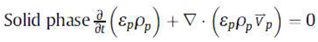
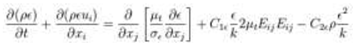
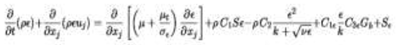
3.1. Governing Equations [42]
The Navier-stokes equations as shown below in Equations 1 – 5 are governing equations that are undertaken for fluid dynamic problems.
- (i)
- Continuity Equation
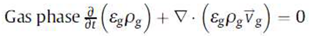 (1)
(1) (2)
(2)- (ii)
- Momentum Equation
 (3)
(3) (4)
(4)- (iii)
- Energy Equation
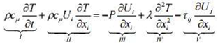 (5)
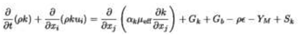
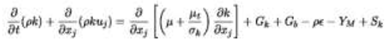
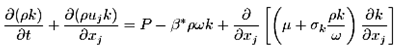
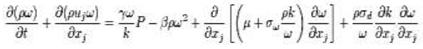
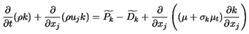
(5)3.2. The Turbulence Models Equations [42]
The turbulence models usually used are the k-ε turbulence model the k-ω turbulence model as shown in Equations 6 – 15.
- (i)
- Standard k-ε turbulence model [43]
 (6)
(6) (7)
(7)- (ii)
- RNG k-ε turbulence model [44]
 (8)
(8)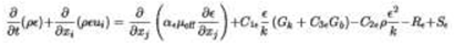 (9)
(9)- (iii)
- Realizable k-ε turbulence model [45]
 (10)
(10) (11)
(11)- (iv)
- k-ω two-equation turbulence model [46]
 (12)
(12) (13)
(13)- (v)
- Transition SST turbulence model [47]
 (14)
(14) (15)
(15) (16)
(16) (17)
(17) (18)
(18) (19)
(19)3.2. Mesh Density
Mesh density typically has three levels: coarse, medium, and fine. Fine mesh represents the highest level of grid precision in mesh generation. The density of the mesh greatly influences the problem's solution. In other words, the precision of the outcomes is may largely depend on the mesh quality [41,42,48]–[51]. Sha et al. [51] concluded that the mesh quality, especially the grid spacing near the wall surface, is crucial for accurate heat flux computations. Zhang and Yu [48] performed a numerical simulation to develop a theoretical framework for designing grid sizes in small-scale structures generated in hypersonic flows, where both viscous and non-viscous flows interact. The results showed that the accuracy of the numerical simulation is influenced by the grid sizes. The best simulation results were obtained when the grid design of the small-scale structure of the interaction shear flows (ISF) theory was used. Similarly, Chao et al. [52] propose that using a refined grid yields improved simulation results of the flow field.
Figure 5 shows a CFD model with different mesh densities which was performed on two different grids to determine the possibility of grid sensitivity. The models were meshed by the same tetragonal cell type. The primary distinction in mesh sensitivity was the cell density. As shown in Figure 5-a, the densest grid comprises 216,440 cells with an average side dimension of 11.3 μm. In contrast, Figure 5-b shows a less dense grid with 30,920 cells and an average side dimension of 22.6 μm. The less dense grid was employed because the results for both grids were nearly identical [53].
3.3. Turbulence Model
Turbulent flow is characterized by unsteady, irregular (aperiodic) motion where mass, momentum, and scalar quantities fluctuate across time and space, enhancing the mixing of matter, momentum, energy, and more, creating swirling patterns known as turbulent eddies. The structure of turbulent flow includes the transfer of energy from larger eddies to smaller ones, as depicted in Figure 6. In the smallest eddies, turbulent energy is transformed into internal energy through viscous dissipation, as illustrated in Figure 7.
In CFD simulations, turbulence models typically fall into three categories: RANS models, LES, and DNS. RANS and LES models are commonly utilized in various simulations, with RANS being a primary tool for burner combustion chamber design. Recently, LES has seen substantial progress and is increasingly influential in the design process [55]. LES model is typically used for transient turbulence models. While RANS model solves few turbulence models with a specific number of equations involved in the model. The Spalart-Allmaras model is categorized as a one-equation turbulence model. Models like Standard k–ε, RNG k–ε, Realizable k–ε, Standard k–ω, and SST k–ω are considered two-equation turbulence models. The V2F model falls under the four-equation category. Steady turbulence RANS models include the Reynolds Stress Model, k–kl–ω Transition Model, and SST Transition Model.
Reis et al. [27] used the standard k-ε, RNG k-ε, the Realizable k-ε and the Reynolds stress models to compare the flow performances of an industrial burner orifice through CFD simulation. Similarly, Eiamsa-ard et al. [56] compared the standard k-ε turbulence model with Reynolds-Stress Model (RSM) for a flow through a circular orifice. The simulation results were consistent with the experimental findings. Nevertheless, the RSM model proved to be more precise in the downstream orifice region compared to the k-ε model.
Coughtrie et al. [57] conducted a numerical study on the flow in a gas-lift digester with a central draft tube, employing various turbulence closure models, including k-ω Shear-Stress-Transport (SST), Renormalization-Group (RNG) k-ε, Linear RSM, and Transition-SST models. Their findings indicated that the Transition-SST model was the most effective in capturing mixing behavior and accurately predicting separation. Therefore, they recommended using the Transition-SST model over k-ε models for similar mixing challenges. Likewise, German and Mahmud [58] studied numerically the performance of different turbulence models using Reynolds-stress turbulence models, RSM and standard k-ε turbulence models in predicting turbulent generation for a non-premixed combusting swirling flow. It was observed that both k-ε and Reynolds-stress turbulence models produced fairly accurate predictions, especially concerning flame properties. However, the k-ε model was unable to replicate the subcritical nature of the isothermal flow, whereas the Reynolds-stress model provided a superior prediction of flame characteristics. Additionally, the Reynolds-stress model yielded better results for gas temperature and oxygen concentration levels in the internal recirculation zone and surrounding the shear region.
4. The Premix Injector
Yatsufusa et al. [59] developed a novel injector designed to directly introduce water into the combustion field to create a water-fuel emulsion. This emulsified fuel helps reduce flame temperature, resulting in lower Nox and PM emissions [59]–[64]. The new injector is designed to facilitate fuel-water internal rapid mixing. In the small mixing chamber, atomization air ensures the quick combination of fuel and water, which is then injected into the chamber. This water, fuel, and air mixture are directly introduced into the combustion field. The newly developed injector, termed the “fuel-water internally rapid mixing type injector. independently introduces fuel and water into a small mixing chamber. Figure 8 provides a detailed cross-sectional view of the injector. The mixing chamber has a capacity of 3.9 mL, with fuel being supplied through a ring-shaped slit (outer diameter: 5.5 mm, slit width: 0.45 mm) and water through a central hole (diameter: 2.0 mm). Additionally, the injector’s swirler generates swirl airflow within the mixing chamber to enhance mixing efficiency [59].
4.1. Fuel-air Premixing
Mixing occurs slowly and is not driven by forced convection. Convection refers to large-scale transport, while turbulence encompasses transport from large to small scales. Turbulent mixing is crucial in practical fluid flows exceeding a millimeter in size. Ultra-low-emission combustors depend on achieving nearly perfect mixture homogeneity before successful combustion. A homogeneous combustible mixture significantly lowers the risk of autoignition. High mixture homogeneity is essential for both reducing Nox emissions and preventing autoignition [66]. Furthermore, effective turbulent flow mixing can be achieved by combining water, fuels, gases, and other substances. The formation of a fuel-air mixture is crucial for combustion modeling and is a complex process that can be executed in various ways using diverse technologies.
Over the past 20 years, numerous researchers have examined spray fuel-air mixing, a field pioneered by the eminent spray researcher Lefebvre [67]. He employed various types of atomizers to mix fuel and air for both internal and external combustion applications. The atomizers developed were highly effective for fuel-air mixing, leading to their widespread production for spray injection applications. With advancements in mixing technologies, fuel-air mixing no longer relies solely on atomizers. External techniques such as turbulence generators, fractal grids, swirling flow, high-pressure fuel injection, and scramjets have been introduced to improve mixing. Cheng et al. [68] examined how initial fuel-air mixing impacts Nox and CO emissions in swirling methane jet flames. They focused on parameters such as the number of swirls used to adjust the initial fuel-air mixing before the swirling flame, the fuel-air momentum flux ratio, and the fuel injection point. Their findings demonstrated robust and rapid mixing in the highly recirculating flame. Additionally, improved mixture homogeneity decreased the characteristic time for Nox formation, leading to a lower Nox emission index.
4.2. Effects of Swirling Flow
For many years, researchers and industries have frequently utilized swirling flows to stabilize high-intensity combustion processes [71,72]. Swirling flow is crucial for forming an internal recirculation zone, generating low-velocity areas where the flame can remain stationary [71,73]. This recirculation zone enhances fuel/air mixing and increases turbulent flame speed by raising turbulence levels [71]. Liu et al. [71] examined how the nozzle gap shroud impacts combustion stability and spray characteristics in a swirl-cup combustor. They looked at various performance aspects, including flame patterns, ignition, and lean blowout. Their findings showed a significant improvement in ignition performance when the fuel/air ratio was below 18% of the ignition limit. Figure 9 illustrates the detailed flow structures within the venturi and the simulated non-reacting flow field inside the combustor model. Interaction between swirling air and jetting air streams from the purge holes notably affected the flow field structure. As h increased from 0.5 mm to 2.5 mm, the Central Recirculation Zone (CRZ) shifted downstream, and the reverse flow velocity decreased.
Rahman et al. [74] conducted a numerical analysis on the performance of the separator, which induces orthogonal driving flow to separate the water-vapor two-phase flow. They used the standard k-ε and realizable k-ε turbulence models in their study. Figure 10 illustrates the velocity vector results for both models. The realizable k-ε turbulence model exhibited high-velocity swirling flow at the center and low-velocity weak swirling flow near the wall. The intense swirling flow at the center generated centrifugal forces, pushing the liquid phase (water) to the outer vortex region, where it accumulated in the area of weak swirling intensity. Huang and Yang [75] considered LES techniques to numerically analyze the effect of inlet swirl on flow development and combustion dynamics in a lean-premixed, swirl-stabilized combustor. The findings indicated that an increase in swirl number pushed the recirculation zone upstream, merging it with the wake recirculation zone. They observed that higher swirl numbers boost turbulence intensity, which in turn reduces flame speed and surface area. However, an excessive swirl could cause the central recirculating flow to invade the inlet annulus, potentially leading to flame flashback.
4.3. Cavitation
Cavitation is a key method for reducing emissions from combustion at the source by enhancing spray breakup and creating smaller droplets inside the combustion chamber. The physical flow within the nozzle injector greatly affects spray formation. High pressure inside the injector drops sharply across the nozzle, accelerating the liquid through the small nozzle. This rapid increase in velocity and decrease in pressure generate cavitation, as shown in Figure 11. Cavitation within the nozzle is one of the most critical factors influencing fuel spray atomization.
Cavitation positively influences the development of fuel spray breakup. Numerous researchers have focused on experimental and numerical methods to better understand this phenomenon and its impact on the durability and performance of diesel fuel injections. Experiments on geometric-induced and string cavitation [77] revealed that the spray angle increases with the presence of string cavitation in the nozzle. Gavaises [78] found that cavitation causes damage at bubble collapse sites, while engine exhaust emissions rise due to the formation of string cavitation structures within the nozzle
Payri et al. [79] conducted an experimental study examining how geometrical parameters influence cavitation phenomena within a visual closed vessel using laser technologies. Their findings indicated that the jet angle significantly impacts cavitation behaviors. Desantes et al. [80] conducted an experimental study on the impacts of cavitation phenomena in the near-nozzle field using visualization techniques to identify cavitation bubbles injected into a pressurized chamber with liquid fuel. They observed a significant increase in spray cone angles and irregularities in spray contour, which were associated with the presence of cavitation bubbles at the orifice outlet. They inferred that this indicated an improvement in atomization due to the collapse of cavitation bubbles at the nozzle exit.
In a similar vein, Payri et al. [81] examined how the cavitation phenomenon impacts the spray cone angle, finding a notable increase as cavitation appeared. Hiroyasu [82] observed a comparable outcome by separately visualizing the internal flow and macroscopic spray from various large-scale nozzles. Sou et al. [83] numerically studied cavitation flow within an injector nozzle using a combination of LES, the Eulerian-Lagrangian Bubble Tracking Method (BTM), and the Rayleigh-Plesset (RP) equation to simulate initial cavitation with cavitation bubble clouds. Their findings showed that using these combined equations yielded accurate predictions of cavitation.
5. Orifice Geometries of Injector
5.1. Orifice Diameter
The design of the nozzle hole significantly affects nozzle orifice flow, spray characteristics, cavitation, and turbulence levels, all of which have an indirect influence on combustion [4,26,31], [77]. Researchers commonly use various types of nozzle orifices, which differ in hole shape (cylindrical and conical) and orifice diameter. Yang et al. [84] discovered that nozzle diameter influences atomization behavior when comparing the spray characteristics of two different nozzle diameters. Both injectors had the same swirl chamber size and tangential inlets. Under identical pressure drops, the spray angle for the 1.5 mm nozzle was smaller than for the 2 mm nozzle. The 1.5 mm nozzle produced a rotating fluid jet, while the 2 mm nozzle created a twisted ribbon-like structure due to stronger swirl effects.
Daikoku and Furudate [85] investigated how cavitation generation and collapse in a nozzle impact liquid breakup, using three different nozzle length-to-diameter ratios. Their findings indicate that disturbances within the nozzle dissipate when flowing through a large L/D ratio nozzle, which does not enhance liquid jet atomization. Conversely, in a small L/D ratio nozzle, cavitation occurs at low injection pressures, unaffected by downstream flow, and promotes liquid jet breakup. This cavitation affects all transitions in a small L/D ratio nozzle, reducing flow velocity and transitioning from a wavy jet to a spray. The liquid velocity for nozzle diameters of 3 mm and 1.5 mm resulted in slower velocities with smaller nozzle diameters, as depicted in Figure 12.
The study also determined that increasing injection pressure leads to a larger spray angle, as illustrated in Figure 13. This finding is consistent with experimental results from [86,87]. Similarly, Sun et al. [88] conducted a numerical study on how the geometrical parameters of a nozzle impact flow and cavitation characteristics within an injector’s nozzle. They found that the ratio of the nozzle’s length to the orifice’s diameter significantly affects these characteristics. Narrowing the orifice diameter increases drag force, sharply reducing flow velocity within the nozzle. Their study concluded that decreasing the nozzle diameter, given a specific length, leads to variations in the distribution of physical fields. Different nozzle diameters cause low (or even negative) pressure at various locations, resulting in distinct cavitation origins.
5.2. Nozzle Hope Shape
When examining the injection behavior of fuel, fuel-air mixing, or fuel-air-water mixing, two common nozzle shapes are employed: conical and cylindrical orifices. Numerous studies, such as [23]–[25,89], have utilized these nozzle shapes to investigate their performance differences in cavitation, flow efficiency (discharge coefficient), exit velocity, spray characteristics, mass flow rate, etc.
Benajes et al. [23]conducted an experimental study to analyze how conical and cylindrical nozzle orifices affect injection rate behaviors in a cavitation test. The experiment compared these two orifice shapes to enhance flow efficiency (discharge coefficient), reduce cavitation, and increase exit velocity. It was noted that the fuel injection rate decreased due to the smaller exit area. Payri et al. [24] noted smooth conditions with cylindrical nozzles. Meanwhile, the mass flow rate for the conical nozzle correlated with the square root of pressure drop when cavitation was absent at the nozzle exit. They also observed an increase in injection velocity due to vapor presence at the orifice outlet for the cylindrical nozzle. Additionally, Han et al. [25] determined that nozzle geometry significantly influences the primary breakup region, comparing conical and cylindrical nozzles.
5.3. Conical Nozzle
A conical nozzle features a cone shape with a half-cone angle when viewed from the side [5,26,53], [76,88]. It’s defined as the ratio of the difference between the nozzle’s inlet diameter and outlet diameter to a constant 10 µm [88,90]. When the orifice coefficient, is positive, the nozzle forms a conical pattern. Conversely, a negative coefficient value results in an inverted conical pattern. Conical nozzles offer a few advantages, such as their simple design and the lack of inflection when propellants are expelled from the combustion chamber. This results in propellants exiting in a straight line from the nozzle throat to the exit, making conical nozzles ideal for solid and hybrid propellant types. However, conical nozzles also have drawbacks, notably significant divergence loss at the exit. As the propellant flows parallel to the centerline, rather than at the cone angle, energy is lost due to divergence, leading to lower nozzle efficiency. The large exit angle further increases divergence loss. Additionally, conical nozzles are heavier because they require more materials compared to other nozzle designs.
A pintle-type nozzle produces conical-shaped sprays and creates a homogeneous mixture to achieve low exhaust emissions during premixed diesel combustion. Unlike a nozzle jet burner, the conical nozzle shape effectively controls partial premixing levels and stabilizes partially premixed flames [91]. A lean, highly homogeneous mixture can be achieved using a conical spray injector in advanced diesel injection. Additionally, directing the fuel jets onto the guide wall just before the nozzle exit enhances the conical spray nozzle, creating a conical spray shape [77]. Furthermore, the conical nozzle offers higher exit density, velocity, and discharge coefficient, helping to suppress cavitation. However, its fuel injection rate is reduced due to the smaller exit diameter.
Jia et al. [77] conducted a numerical simulation examining cavitation within a conical spray nozzle. Their findings showed that cavitation affects the film thickness, fuel velocity at the nozzle’s exit, and spray angle. Pougatch et al. [92] conducted a numerical study on how conical nozzle attachments influence spray dispersion in a fluidized bed. They discovered that smaller attachment angles stabilize the spray, whereas larger angles lead to destabilization. Moreover, Battistoni et al. [5] investigated cavitation flow and spray through CFD simulation, comparing cylindrical and conical nozzles, as well as diesel and biodiesel fuels. They found that fuel type had a minimal impact on cavitation regions, while nozzle shape was crucial. Cylindrical nozzles produced higher cavitating flow, whereas conical nozzles tended to reduce cavitation. However, diesel fuel showed greater liquid penetration in conical convergent nozzles. Elbaz et al. [91] explored the stabilization mechanisms, stability limits, and flow field structures of highly stabilized partially premixed methane flames in a concentric flow conical nozzle burner with air co-flow. They found that introducing air co-flow enhanced stability, and as the air co-flow velocity increased, most of the stable flames became nearly fully premixed.
5.4. Cylindrical Nozzle
The standard nozzle shape is cylindrical, with identical inlet and outlet diameters. This nozzle features a cylindrically shaped head at the exit, as depicted in Figure 14. Compared to conical nozzles, cylindrical nozzles are more prone to cavitation due to their smaller conicity and lower rounding radii values [89].
The mass flow rate of a cylindrical nozzle increases in proportion to the square root of the pressure differential until it reaches stability, a condition caused by cavitation. This critical cavitation point, defined as Kcrit, marks where the mass flow rate begins to stabilize. As a cylindrical nozzle is prone to cavitation, this phenomenon is observed when mass flow rate stabilization happens at a specific injection pressure, leading to reduced discharge pressure, also known as choking. Cavitation ensues if the cavitation number under these pressure conditions falls below the critical value, Kcrit [81].
Payri et al. [81] investigated the effects of cavitation on internal flow and the macroscopic spray behavior in diesel injection nozzles, comparing cylindrical and conical types. They noted an exception for the cylindrical nozzle, which showed a decreased discharge coefficient at each injection pressure with a pronounced Reynolds number, as depicted in Figure 15. This drop in the discharge coefficient was linked to a reduction in mass flow rate due to cavitation. Additionally, the increase in the discharge coefficient halted upon the onset of cavitation, indicating that the discharge coefficient is dependent on the cavitation number at that point.
5.1. Influences of Hole Shaped Nozzles
In research on fuel properties and spray characteristics, cylindrical and conical hole nozzles are frequently selected. Since biodiesel exhibits a slightly higher mass flow in cavitating nozzles, using hole-shaped nozzles with similar or slightly higher mass flow can help reduce diesel cavitation. Som et al. [26] conducted numerical and experimental studies on how hole shape and hydrogenising affect biodiesel sprays. They discovered that conicity notably reduced cavitation and turbulence levels within the nozzle orifice. Additionally, conicity was found to slow down the primary breakup process, resulting in larger spray droplets, greater penetration, and a smaller cone angle.
Hountalas et al. [94] conducted an experimental study on three different nozzle hole types to assess the impact of conical-hole nozzles on engine performance and emissions. The results showed that the divergent nozzle hole produced more soot, but lower Nox emissions compared to the other two nozzle types.
6. Spray Characteristics
Spray nozzles operate under different conditions based on their design. When selecting an appropriate nozzle, key spray characteristics such as spray pattern, capacity, impact, angle, and droplet size must be considered. These precision components are engineered to achieve specific spray characteristics under defined conditions. Factors like seat angle, streamwise or tangential velocity, and nozzle exit diameter can influence these characteristics. Therefore, optimizing these parameters is essential to ensure acceptable spray quality for a given application [95]. The physical properties significantly influence spray characteristics, particularly affecting spray atomization. Key factors include viscosity, density, and surface tension [96].
Extensive studies have been conducted on swirl burners with cone-shaped sprays through experiments and simulations. Figure 16 illustrates the progression from a swirling jet to the complete atomization of the spray cone. At low mass flow rates, a jet with a circular cross-section form near the nozzle. As the spray transitions, it adopts a flatter cross-section, resembling a twisted ribbon or thin sheet. This phenomenon typically occurs below the jet due to the interplay between the jet’s swirl strength and the fluid’s viscous stress [84]. Furthermore, Figure 17 provides a 3-D snapshot of the flow field and droplets (black dots), with the red line indicating gas temperatures above 1500 K. It was presented by Jones et al. [55] when they investigated turbulent mixing, fuel spray dispersion, evaporation, and combustion within a gas-turbine combustor geometry. Their comparison of the fuel spray model results accurately reflected the measured SMD and droplet velocity.
6.1. Spray Penetration
It refers to the maximum distance a liquid or liquid-fuel spray reaches when injected from the nozzle head into stagnant air. This distance is determined by the balance between the kinetic energy of the initial fuel jet and the aerodynamic resistance of the surrounding gas. Typically, a compact and narrow spray achieves greater penetration, whereas a spray with lower penetration usually has a high cone angle and is well atomized, facing more air resistance. Fluid properties such as surface tension, viscosity, and density influence droplet size and the ease of atomization after being injected from an orifice. Figure 18 demonstrates how different biofuel blends affect particle penetration and compares the maximum length within the injector for these various blends [18].
6.2. Spray Angle and Dispersion
The cone angle of a spray is typically measured using image processing methods in experimental studies. In numerical simulations, it can be determined through either image processing or droplet density dispersion distribution. Khalid et al. [65] utilized direct photography to study the effects of diesel-water emulsification on mixture formation, combustion, and flame development in a burner system. Their findings indicated that the higher water content increased viscosity, resulting in greater penetration length and a smaller spray angle. Consequently, this led to a lower combustible mixture and reduced flame penetration. The spray angle and penetration were analysed using image processing techniques.
Som et al. [4] performed a simulation study to examine the flow and spray behaviour of biodiesel compared to petrodiesel. Figure 19 displays the droplet density results in a plotted graph, with a black box in the centre representing the nozzle for reference. The dispersion distribution of droplets from both fuels allows for a comparison of spray angles. Fung [97] conducted both experimental and numerical studies on the spray characteristics of nasal spray devices, focusing on spray angle. The numerical analysis employed two different spray models, TAB and ETAB, and the results were compared with experimental data. The findings indicated a good agreement between the simulation and experimental results. During the later stages, specifically at injection times between 4 and 10ms for a 6-bar case, the maximum observed difference was approximately 2 degrees.
6.3. Spray Droplets
When liquid is mixed with air pressure in two-fluid nozzles or with liquid pressure in hydraulic nozzles, potential energy is generated due to the nozzle’s geometry. This energy causes the liquid to spread into thin ligaments, which then break up into small spherical pieces called drops, droplets, or liquid particles. A droplet, a small spherical liquid particle, remains round due to surface tension. This same surface tension causes droplets and soap bubbles to attract each other into a spherical shape, resisting spreading. Sprays form when the interface between liquid and gas is disturbed, producing liquid droplets [18]. Figure 20 illustrates the particle size for various biofuel blends, while Figure 21 shows the spray pattern from a spray nozzle.
6.4. Sauter Mean Diameter (SMD)
The SMD is the diameter of a droplet that has the same surface-to-volume ratio as the entire spray. This measurement, often abbreviated as SMD or D32 [66], is crucial for combustion applications. Predicting the SMD aids experimental studies by providing insights into specific modifications related to spray injection. Additionally, combustion performance and emission levels can be forecasted based on the SMD predictions. Smaller SMD values indicate a higher surface area per unit volume. This means that droplets will have more surface area, enhancing the efficiency of evaporation and mixture formation [98].
Jedelský and Jícha [99] conducted an experimental study on optimizing multi-hole effervescent atomizers for industrial burners, utilizing oil-based fossil fuels and bio- or waste fuels to reduce emissions. Their Phase-Doppler anemometry results revealed that the D32 profiles of these atomizers have an inversely bell-shaped distribution, with the minimum value located along the nozzle axis. Furthermore, Broukal and Hájek [16] conducted a validation study of an effervescent spray model with secondary atomization intended for use in a large-scale furnace. Their findings revealed an exaggerated bimodal distribution in drop sizes and inconsistencies in predicting the radial evolution of SMD. Despite this, there was a partial qualitative agreement in the radial evolution of drop size distributions. Fung et al. [100] numerically investigated the spray breakup mechanism at low pressure in a nasal spray to validate experimental results. They simulated the secondary breakup using the Taylor Analogy Breakup (TAB) model and the spread parameters of the Rosin-Rammler distribution. The model predicted the spray plume shape and droplet size distribution (D30, D32) for low-pressure applications, and the validation data was utilized for further simulations. Yasin et al. [101] utilized CFD simulation to compare the Discrete Multicomponent (DM) model with the traditional Continuous Thermodynamics (CTM) model for spray formation using diesel and biodiesel. Their study found that biodiesel produced larger SMD droplet sizes than diesel, consistent with experimental measurements.
6.5. Influence of Fuel on Spray Characteristics
Lin et al. [96] performed an experimental study focusing on how different fuels influence spray characteristics. The fuels examined were EME20 (emulsified WME with 20% water), WME (waste cooking oil methyl esters), and Diesel fuel. Figure 22 presents the measured spray cone angles for diesel fuel and WME. The graph indicates that there is no significant difference in spray angles, likely due to the higher viscosity of the emulsified fuel. Additionally, the EME spray angle was initially small during the early stages of atomization but increased significantly after 2 ms of spraying, potentially due to the micro-explosion of an emulsion droplet.
Figure 23 and Figure 24 display high-speed images of EMW20 and diesel fuel sprays at 380°C. Initially, the EME spray angle is small but gradually increases during atomization, around 2 to 3 ms. The improvement in spraying is more notable as the temperature rises. From a microscopic view, in water-in-oil (w/o) biodiesel emulsions, water serves as the dispersed phase, while WME is the continuous phase. In the combustion chamber, temperature increases during piston compression heat the droplets significantly since water microcells are encapsulated in oil. This leads to a “micro-explosion. occurring when the saturated vapor pressure of the dispersed water phase reaches critical pressure, causing droplets to burst. This micro-explosion results in secondary atomization, producing many fine droplets that evaporate quickly. As Figure 29 shows, the violent disintegration of EME droplets in later spraying stages generates fine secondary droplets with a larger physical volume, enhancing fuel spray characteristics. Consequently, the spray angle increases over time as illustrated in Figure 28. Large EME droplets penetrating the combustion chamber undergo micro-explosions, enhancing local mixing and combustion efficiency [96].
Figure 23.
Pattern of fuel spray [96].
Figure 23.
Pattern of fuel spray [96].
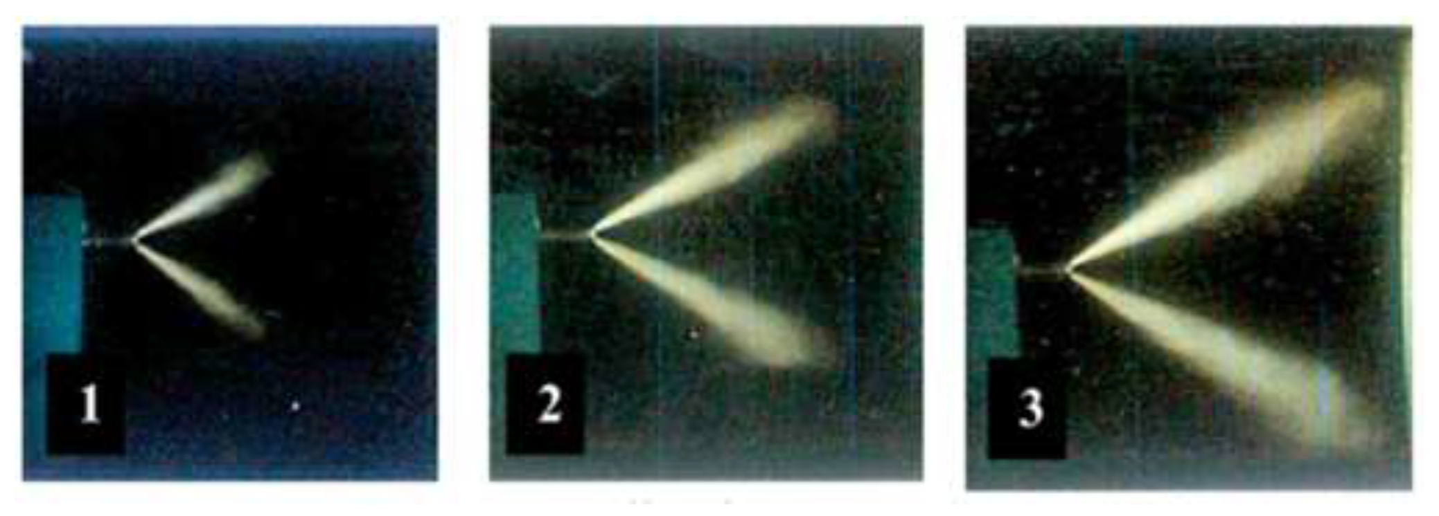
Figure 24.
Pattern of EMW20 fuel spray [96].
Figure 24.
Pattern of EMW20 fuel spray [96].

Ing et al. [18] presented a numerical analysis of biofuel spray characteristics, focusing on blends of Refined, Bleached, and Deodorized Palm Oil (RBDPO) and Commercial Diesel Fuel (CDF) in a gas turbine. They compared various biofuel blends to pure diesel, categorizing the blends into B5, B10, B15, and B20 ratios. The study revealed that increasing the percentage of RBDPO results in higher SMD and particle penetration. Additionally, SMD was found to rise with increasing density, surface tension, and viscosity. Biodiesel demonstrated a higher SMD compared to standard diesel. Figure 25 illustrates the predicted SMD for different biodiesel blends in comparison to diesel.
6.6. Spray Analysis
Spray characteristics are typically assessed by analyzing SMD, spray angle, and spray penetration length. Various types of spray analysis methods are used to compare these parameters effectively. Battistoni et al. [5] conducted a simulation study comparing biodiesel and diesel. The findings indicated that biodiesel exhibited similar behavior with both conical and cylindrical geometrical shapes. In contrast, diesel displayed distinct breakup characteristics, being more responsive to different hole shapes. Diesel produced a faster and denser spray, maintaining compactness longer with a conical hole, but exhibited enhanced spray breakup at a cavitating hole. Figure 26 presents the penetration of diesel and biodiesel sprays for different hole shapes. The diesel spray from the conical hole demonstrates higher liquid penetration. Conversely, both diesel and biodiesel sprays from the cylindrical hole display lower and comparable penetration trends over time [5].
Yasin et al. [101] performed a numerical work comparing the DM model with the traditional CTM model for diesel and biodiesel fuels. They also made a semi-quantitative comparison between the predicted spray-combustion characteristics and optical measurements of a swirl-stabilized flame for both fuels. It was observed that the Sauter mean diameter D32, normalized volume flux V, and normalized droplet density Dρ, along with all other spray variables, behaved as expected at their respective maximum values, except for D32, which was normalized using the characteristic diameter, d, from the Rosin Rammler distribution function in the spray boundary condition specification. The experimental findings showed that biodiesel had a droplet size, volume flux, and droplet density 20% higher than diesel. The simulation results similarly indicated higher droplet size, volume flux, and droplet density for biodiesel compared to diesel. Figure 27 depicts the normalized D32, V, and Dρ.
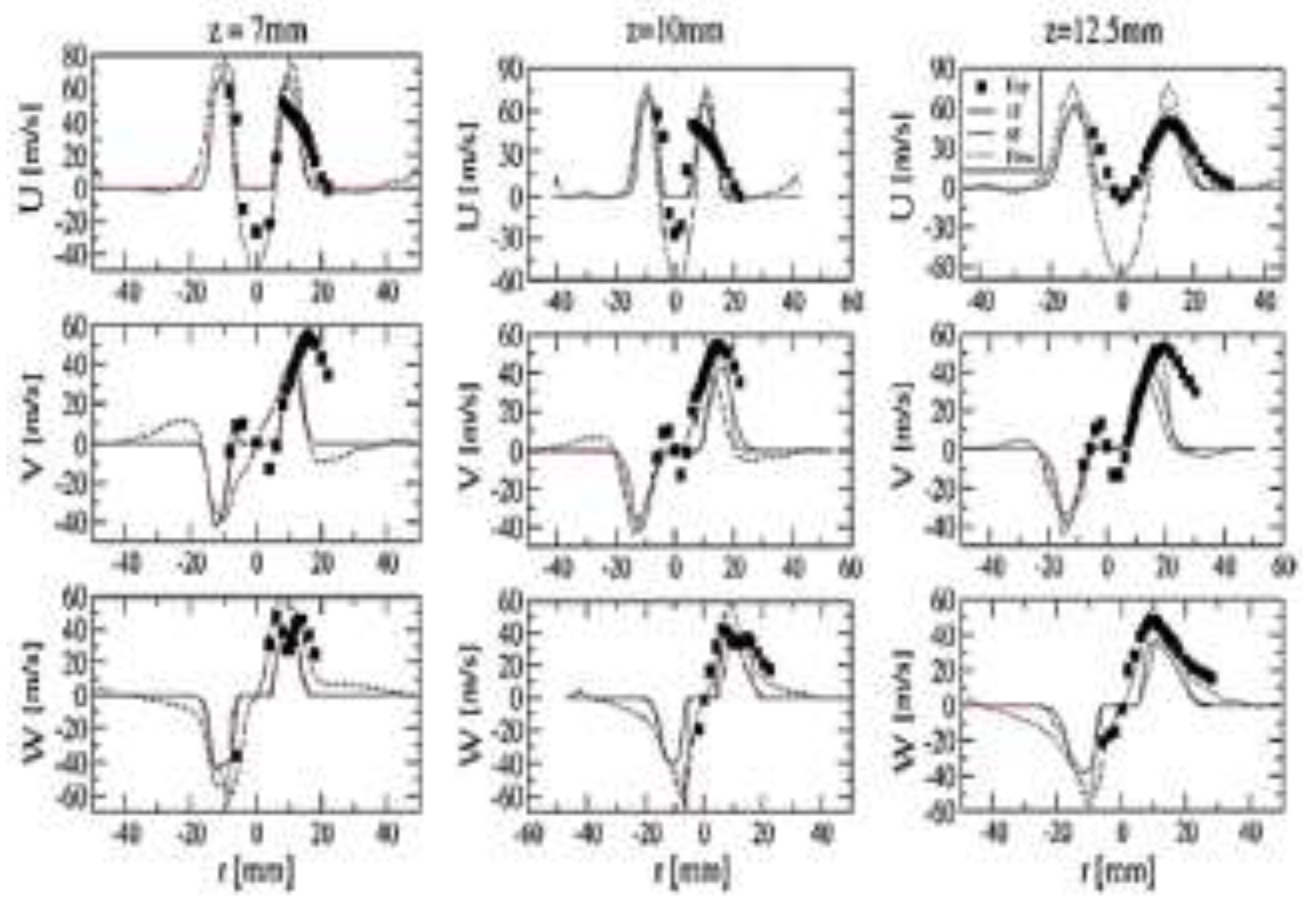
However, Jones et al. [55] conducted a numerical study using LES to examine turbulent mixing, fuel spray dispersion, evaporation, and combustion within a gas-turbine combustor geometry (the DLR Generic Single Sector Combustor). They analysed spray statistics and how these are influenced by the combusting flow field, predicting droplet diameter, velocity, and SMD. The dispersed phase model (fuel spray) employed in the study accurately replicated SMD and droplet velocity using LES. They also highlighted the need for future research on the suitability of a Lagrangian formulation for the dispersed phase near the injector. These methods are generally applicable to dilute sprays with sufficiently small droplet sizes, considered point sources of mass, momentum, species, and energy. Figure 28 shows the simulated SMD results at six different axial locations: z = 7 mm, 10 mm, 12.5 mm, 15 mm, 20 mm, and 30 mm. Figure 29 illustrates the radial profile of particle velocity along different axial locations: z = 7 mm, 10 mm, and 12.5 mm, based on the LES simulation.
Figure 28.
SMD at six axial positions [55].
Figure 28.
SMD at six axial positions [55].
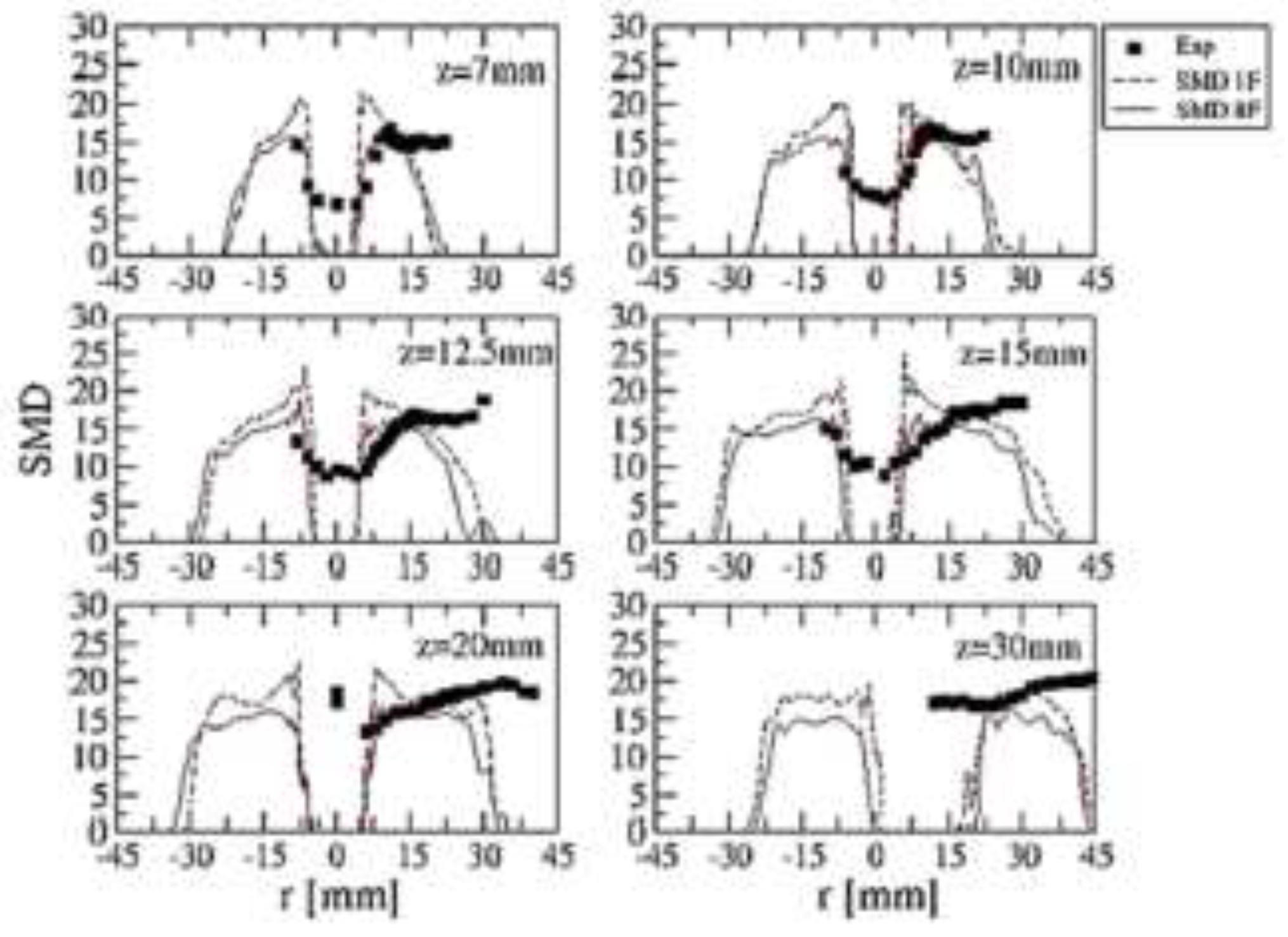
Figure 29.
Radial particle velocity at three axial positions [55].
Figure 29.
Radial particle velocity at three axial positions [55].
7. Conclusions
Alternative fuels have gained widespread attention worldwide due to the need for a global environmental solution. Alternative fuels and orifice characteristics play a significant role in reducing greenhouse gas emission. They collectively have the capability to enhance combustion performance and improve energy efficiency. The following conclusions can be summarised as below:
- (i)
- Biodiesel from crude palm oil (CPO) is capable to reduce the cavitation inside the orifice.
- (ii)
- The Reynolds-stress turbulence model and the Transition SST model are found to reasonably be the better turbulence models in the simulation of mixing.
- (iii)
- Premix injector can reduce emission in combustion process.
- (iv)
- Application of swirling flow enhances the fuel and air mixing.
- (v)
- Although cavitation could significantly improve the spray atomization, however, it may damage the orifice.
- (vi)
- The cylindrical orifice is concluded as a highly cavitating orifice, while conical orifice is capable to reduce the cavitation inside the orifice.
- (vii)
- Spray characteristics can enhance the overall combustion performances.
Author Contributions
Conceptualization and methodology; Amir Khalid, Djamal Hissein Didane; formal analysis and investigation. Ronny Yii Shi Chin; writing—original draft preparation, Djamal Hissein Didane; writing—review and editing, Amir Khalid; supervision. All authors have read and agreed to the published version of the manuscript.
Funding
This research received no external funding.
Data Availability Statement
Data is contained within the article or supplementary material.
Acknowledgments
The authors would also like to thank the Faculty of Mechanical and Manufacturing Engineering, Universiti Tun Hussein Onn Malaysia for its support.
Conflicts of Interest
The authors declare no conflicts of interest.
References
- Y. S. M. Altarazi, T. Yusaf, J. Yu, E. Gires, M. F. A. Ghafir, and J. Lucas. A review of engine performance and emissions using single and dual biodiesel fuels: Research paths, challenges, motivations and recommendations. Fuel 2022, 326, 125072. [Google Scholar] [CrossRef]
- T. N. Tuan, H. Okada, T. Tsukamoto, K. Ohe, and K. Iwasawa. Effect of rounding-off nozzle hole inlet on fuel injection and combustion characteristics under high-temperature and high-pressure. Marine Engineering 2007, 42, 288–294. [Google Scholar] [CrossRef] [PubMed]
- Y. Tezel. Spray characteristics of emulsified biodiesel-diesel blends in a constant volume combustion chamber.” Izmir Institute of Technology (Turkey), 2020.
- S. Som, D. E. Longman, A. I. Ramírez, and S. K. Aggarwal. A comparison of injector flow and spray characteristics of biodiesel with petrodiesel. Fuel 2010, 89, 4014–4024. [Google Scholar] [CrossRef]
- M. Battistoni and C. N. Grimaldi. Numerical analysis of injector flow and spray characteristics from diesel injectors using fossil and biodiesel fuels. Applied Energy 2012, 97, 656–666. [Google Scholar] [CrossRef]
- H. Zhou, Y. Yang, H. Liu, and Q. Hang. Numerical simulation of the combustion characteristics of a low NOx swirl burner: Influence of the primary air pipe. Fuel 2014, 130, 168–176. [Google Scholar] [CrossRef]
- S. Som, S. K. Aggarwal, E. M. El-Hannouny, and D. E. Longman. Investigation of nozzle flow and cavitation characteristics in a diesel injector. Journal of Engineering for Gas Turbines and Power 2010, 132, 42802. [Google Scholar] [CrossRef]
- N. S. M. Yaacob, A. Khalid, N. Jaat, A. R. Andsaler, M. A. Azizul, and A. Sapit. Simulation and modelling of spray characteristics, spray penetration length and injection pressure of biodiesel. in AIP Conference Proceedings, 2024, vol. 2998, no. 1.
- P. Hariharan, C. Periasamy, and S. R. Gollahalli. Effect of elliptic burner geometry and air equivalence ratio on the nitric oxide emissions from turbulent hydrogen flames. International journal of hydrogen energy 2007, 32, 1095–1102. [Google Scholar] [CrossRef]
- J. Ravikumar and S. Saravanan. Performance and emission analysis on blends of diesel, restaurant yellow grease and n-pentanol in direct-injection diesel engine. Environmental Science and Pollution Research 2017, 24, 5381–5390. [Google Scholar] [CrossRef]
- K. M. Rahman, M. Mashud, M. Roknuzzaman, and A. Al Galib. Biodiesel from Jatropha oil as an alternative fuel for diesel engine. International Journal of Mechanical & Mechatronics (IJMME-IJENS) 2010, 10, 1–6. [Google Scholar]
- S. A. Raja. Biodiesel production from jatropha oil and its characterization. Res J Chem Sci 2011, 1, 81–87. [Google Scholar]
- G. Antolın, F. V Tinaut, Y. Briceno, V. Castano, C. Perez, and A. I. Ramırez. Optimisation of biodiesel production by sunflower oil transesterification. Bioresource technology 2002, 83, 111–114. [Google Scholar] [CrossRef] [PubMed]
- G. Corro, N. Tellez, F. Bañuelos, and M. E. Mendoza. Biodiesel from Jatropha curcas oil using Zn for esterification step and solar radiation as energy source. Fuel 2012, 97, 72–79. [Google Scholar] [CrossRef]
- G. Vicente, M. Martınez, and J. Aracil. Integrated biodiesel production: a comparison of different homogeneous catalysts systems. Bioresource technology 2004, 92, 297–305. [Google Scholar] [CrossRef]
- J. Broukal and J. Hájek. Validation of an effervescent spray model with secondary atomization and its application to modeling of a large-scale furnace. Applied Thermal Engineering 2011, 31, 2153–2164. [Google Scholar] [CrossRef]
- S. Bari, C. Zhang, F. Kafrawi, and K. H. Lee. Study of Spray Behaviors to Correlate with Engine Performance and Emissions of a Diesel Engine Using Canola-Based Biodiesel. Fuels 2022, 3, 87–112. [Google Scholar] [CrossRef]
- M. N. M. Jaafar, M. S. A. Ishak, and M. A. A. Arizal. Spray Characteristic of Palm Biofuel Blends. International Journal of Mechanical and Materials Engineering 2010, 5, 214–221. [Google Scholar]
- H. Lefebvre. Atomization and Sprays (Hemisphere, New York, 1989). Google Scholar.
- Khalid, N. Tamaldin, M. Jaat, M. F. M. Ali, B. Manshoor, and I. Zaman. Impacts of biodiesel storage duration on fuel properties and emissions. Procedia Engineering 2013, 68, 225–230. [Google Scholar] [CrossRef]
- Khalid et al.. Effects of storage duration on biodiesel properties derived from waste cooking oil. Applied Mechanics and Materials 2014, 554, 494–499. [CrossRef]
- H. K. Suh, S. H. Park, and C. S. Lee. Experimental investigation of nozzle cavitating flow characteristics for diesel and biodiesel fuels. International Journal of Automotive Technology 2008, 9, 217–224. [Google Scholar] [CrossRef]
- J. Benajes, J. V. Pastor, R. Payri, and A. H. Plazas. Analysis of the influence of diesel nozzle geometry in the injection rate characteristic. Journal of Fluids Engineering 2004, 126, 63–71. [Google Scholar] [CrossRef]
- R. Payri, J. M. Garcia, F. J. Salvador, and J. Gimeno. Using spray momentum flux measurements to understand the influence of diesel nozzle geometry on spray characteristics. Fuel 2005, 84, 551–561. [Google Scholar] [CrossRef]
- J.-S. Han, P.-H. Lu, X.-B. Xie, M.-C. Lai, and N. A. Henein. Investigation of diesel spray primary break-up and development for different nozzle geometries. SAE Technical Paper, 2002.
- S. Som, A. I. Ramirez, D. E. Longman, and S. K. Aggarwal. Effect of nozzle orifice geometry on spray, combustion, and emission characteristics under diesel engine conditions. Fuel 2011, 90, 1267–1276. [Google Scholar] [CrossRef]
- L. Reis, J. A. Carvalho Jr, M. A. R. Nascimento, L. O. Rodrigues, F. L. G. Dias, and P. M. Sobrinho. Numerical modeling of flow through an industrial burner orifice. Applied Thermal Engineering 2014, 67, 201–213. [Google Scholar] [CrossRef]
- L. Huang, Z. Li, R. Sun, and J. Zhou. Numerical study on the effect of the Over-Fire-Air to the air flow and coal combustion in a 670 t/h wall-fired boiler. Fuel processing technology 2006, 87, 363–371. [Google Scholar] [CrossRef]
- L. Zeng, Z. Li, G. Zhao, S. Shen, and F. Zhang. Numerical simulation of combustion characteristics and NO x emissions in a 300 MWe utility boiler with different outer secondary-air vane angles. Energy & Fuels 2010, 24, 5349–5358. [Google Scholar]
- G. E. Ballachey and M. R. Johnson. Prediction of blowoff in a fully controllable low-swirl burner burning alternative fuels: Effects of burner geometry, swirl, and fuel composition. Proceedings of the Combustion Institute 2013, 34, 3193–3201. [Google Scholar] [CrossRef]
- Miller. Fuel considerations and burner design for ultra-supercritical power plants. in Ultra-Supercritical Coal Power Plants, Elsevier, 2013, pp. 57–80.
- Hayyan et al.. Ethanesulfonic acid-based esterification of industrial acidic crude palm oil for biodiesel production. Bioresource technology 2011, 102, 9564–9570. [CrossRef]
- S. H. Goh, Y. M. Choo, and A. S. H. Ong. Minor components in palm oil.. in Proceedings of the 1987 International Oil Palm/Palm Oil Conference. Progress and Prospects. Conference II. Technology, 29 June-1 July 1987, Kuala Lumpur, Malaysia., 1988, pp. 95–101.
- F. Motasemi and F. N. Ani. The production of biodiesel from waste cooking oil using microwave irradiation. Jurnal Mekanikal, 2011; 1.
- S. Bari, T. H. Lim, and C. W. Yu. Effects of preheating of crude palm oil (CPO) on injection system, performance and emission of a diesel engine. Renewable energy 2002, 27, 339–351. [Google Scholar] [CrossRef]
- P. Benjumea, J. Agudelo, and A. Agudelo. Basic properties of palm oil biodiesel–diesel blends. Fuel 2008, 87, 2069–2075. [Google Scholar] [CrossRef]
- Khalid, C. Y. M. Jaat, I. Zaman, B. Manshoor, and M. F. M. Ali. Effect of preheated fuel on mixture formation of biodiesel spray. in Applied Mechanics and Materials 2013, 393, 493–498. [Google Scholar]
- Khalid, M. F. Sies, B. Manshoor, L. Latip, and S. H. Amirnordin. Investigation of Mixture formation and Flame Development in Emulsified Biodiesel Burner Combustion.
- K. Phoungthong et al.. Emissions of particulate matter and associated polycyclic aromatic hydrocarbons from agricultural diesel engine fueled with degummed, deacidified mixed crude palm oil blends. Journal of Environmental Sciences 2013, 25, 751–757. [Google Scholar] [CrossRef] [PubMed]
- M. N. M. Jaafar, Y. A. Eldrainy, and M. H. Asril. Experimental investigation of spray characteristics of refined bleached and deodorized palm oil and diesel blends using phase Doppler particle analyzer. International Journal of Physical Sciences 2011, 6, 6674–6680. [Google Scholar]
- W. Zuo. Introduction of Computational Fluid Dynamics. St. Petersburg, 2005.
- G. Tingwen Li, S. Pannala, M. Shahnama, and M. Syamlal. CFD simulations of circulating fluidized bed risers, part I: Grid study. Powder Technology 2014, 254, 170–180. [Google Scholar] [CrossRef]
- H. K. Versteeg and W. Malalasekera, An introduction to computational fluid dynamics: the finite volume method. Pearson Education, 2007.
- Choundhury. Introduction to the renormalization group method and turbulence modelling. Fluent Inc., TM-107, 1993.
- T. -H. Shih, W. W. Liou, A. Shabbir, Z. Yang, and J. Zhu. A new k-ϵ eddy viscosity model for high reynolds number turbulent flows. Computers & Fluids 1995, 24, 227–238. [Google Scholar]
- C. Wilcox. Formulation of the kw turbulence model revisited. AIAA journal 2008, 46, 2823–2838. [Google Scholar] [CrossRef]
- R. Menter, R. B. Langtry, S. R. Likki, Y. B. Suzen, P. G. Huang, and S. Völker. A correlation-based transition model using local variables—part I: model formulation. Journal of turbomachinery 2006, 128, 413–422. [Google Scholar] [CrossRef]
- H. R. Zhang and Y. Yu. A guidance to grid size design for CFD numerical simulation of hypersonic flows. Procedia Engineering 2013, 67, 178–187. [Google Scholar] [CrossRef]
- H. D. Djamal, Q. Y. Woon, M. S. Suzairin, and S. H. Amirnordin. Effects of Geometrical Parameters to the Performance of Louvered Fin Heat Exchangers. Applied Mechanics and Materials 2015, 773, 398. [Google Scholar]
- S. H. Amirnordin, H. D. Djamal, M. Norani Mansor, A. Khalid, M. S. Suzairin, and V. R. Raghavan. Pressure drop and heat transfer characteristics of louvered fin heat exchangers. Applied Mechanics and Materials 2014, 465, 500–504.
- S. Pan, D. H. Feng, G. H. Ding, Z. Tian, Y. Yang, and H. Li. Grid dependency and convergence of hypersonic aerothermal simulation. Acta Aeronautica et Astronautica Sinica 2010, 31, 493–499. [Google Scholar]
- YAN, J. YU, and J. LI. Scheme effect and grid dependency in CFD computations of heat transfer. Acta Aerodynamica Sinica 2006, 1, 22. [Google Scholar]
- Dorri and, A. Hoxha. Influence of hole geometry in the cavitation phenomena of diesel injectors, a numerical investigation. Goriva i maziva: časopis za tribologiju, tehniku podmazivanja i primjenu tekućih i plinovitih goriva i inžinjerstvo izgaranja 2009, 48, 361–371. [Google Scholar]
- L. F. Richardson, Weather prediction by numerical process. Cambridge University Press, 2007.
- W. P. Jones, A. J. Marquis, and K. Vogiatzaki. Large-eddy simulation of spray combustion in a gas turbine combustor. Combustion and Flame 2014, 161, 222–239. [Google Scholar] [CrossRef]
- S. Eiamsa-ard, A. Ridluan, P. Somravysin, and P. Promvonge. Numerical investigation of turbulent flow through a circular orifice. KMITL Sci. J 2008, 8, 44–50. [Google Scholar]
- R. Coughtrie, D. J. Borman, and P. A. Sleigh. Effects of turbulence modelling on prediction of flow characteristics in a bench-scale anaerobic gas-lift digester. Bioresource technology 2013, 138, 297–306. [Google Scholar] [CrossRef]
- E. German and T. Mahmud. Modelling of non-premixed swirl burner flows using a Reynolds-stress turbulence closure. Fuel 2005, 84, 583–594. [Google Scholar] [CrossRef]
- T. Yatsufusa, Y. Kidoguchi, and D. Nakagawa. Improvement of emissions and burning limits in burner combustion using an injector on the concept of fuel-water internally rapid mixing. Journal of Energy and Power Engineering 2014, 8, 11. [Google Scholar]
- S. R. GOLLAHALLI. An experimental study of the combustion of unsupported drops of residual oils and emulsions. Combustion Science and Technology 1979, 19, 245–250. [Google Scholar] [CrossRef]
- J. C. Lasheras, A. C. Fernandez-Pello, and F. L. Dryer. Initial observations on the free droplet combustion characteristics of water-in-fuel emulsions. Combustion Science and Technology 1979, 21, 1–14. [Google Scholar] [CrossRef]
- Y. Mizutani and A. Taki. Burning and emission characteristics and combustion mechanisms of water-in-oil-emulsion sprays: 1st report, properties of emulsions and their burning and emission characteristics. Transactions of the Japan Society of Mechanical Engineers, Series B 1981, 47, 2379–2385. [Google Scholar] [CrossRef]
- H. Hiroyasu, M. Arai, and K. Nishida. The Combustion of Water-in-Heavy Oil Emulsions: 1st Report, Combustion Characteristics of Emulsion Sprays, J. J. JSME (B) 1985, 48, 1182–1188. [Google Scholar]
- T. Yatsufusa, T. Kumura, Y. Nakagawa, and Y. Kidoguchi. Advantage of using water-emulsified fuel on combustion and emission characteristics. Fuel, 2009.
- Khalid, S. H. Amirnordin, L. Lambosi, B. Manshoor, M. F. Sies, and H. Salleh. Spray characteristic of diesel-water injector for burner system. Advanced Materials Research, 2014. [Google Scholar]
- H. Lefebvre and D. R. Ballal, Gas turbine combustion: alternative fuels and emissions. CRC press, 2010.
- H. Lefebvre and V. G. McDonell, Atomization and sprays. CRC press, 2017.
- T. S. Cheng et al.. Effects of fuel-air mixing on flame structures and NOx emissions in swirling methane jet flames. in Symposium (International) on Combustion, 1998, vol. 27, no. 1, pp. 1229–1237.
- M. Stöhr, C. M. Arndt, and W. Meier. Transient effects of fuel–air mixing in a partially-premixed turbulent swirl flame. Proceedings of the Combustion Institute 2015, 35, 3327–3335. [Google Scholar] [CrossRef]
- Khalid and, B. Manshoor. Analysis of mixture formation and flame development of diesel combustion using a rapid compression machine and optical visualization technique. Applied Mechanics and Materials 2013, 315, 293–298. [Google Scholar] [CrossRef]
- Liu, F. Liu, J. Yang, Y. Mu, and G. Xu. Investigations of the effects of spray characteristics on the flame pattern and combustion stability of a swirl-cup combustor. Fuel 2015, 139, 529–536. [Google Scholar] [CrossRef]
- N. Syred and J. M. Beer. Combustion in swirling flows: a review. Combustion and flame 1974, 23, 143–201. [Google Scholar] [CrossRef]
- J. Driscoll and J. Temme. Role of swirl in flame stabilization. in 49th AIAA Aerospace Sciences Meeting including the New Horizons Forum and Aerospace Exposition, 2011, p. 108.
- M. M. Rahman, N. Tanaka, S. Yokobori, and S. Hirai. Three Dimensional Numerical Analysis of Two Phase Flow Separation Using Swirling Fluidics. Energy and Power Engineering 2013, 5, 301. [Google Scholar] [CrossRef]
- Y. Huang and V. Yang. Effect of swirl on combustion dynamics in a lean-premixed swirl-stabilized combustor. Proceedings of the Combustion Institute 2005, 30, 1775–1782. [Google Scholar] [CrossRef]
- Mohan, W. Yang, and S. Chou. Cavitation in injector nozzle holes–a parametric study. Engineering Applications of Computational Fluid Mechanics 2014, 8, 70–81. [Google Scholar] [CrossRef]
- M. Jia, M. Xie, H. Liu, W.-H. Lam, and T. Wang. Numerical simulation of cavitation in the conical-spray nozzle for diesel premixed charge compression ignition engines. Fuel 2011, 90, 2652–2661. [Google Scholar] [CrossRef]
- M. Gavaises. Flow in valve covered orifice nozzles with cylindrical and tapered holes and link to cavitation erosion and engine exhaust emissions. International Journal of Engine Research 2008, 9, 435–447. [Google Scholar] [CrossRef]
- R. Payri, F. J. Salvador, J. Gimeno, and J. De la Morena. Study of cavitation phenomena based on a technique for visualizing bubbles in a liquid pressurized chamber. International Journal of Heat and Fluid Flow 2009, 30, 768–777. [Google Scholar] [CrossRef]
- J. M. Desantes, R. Payri, F. J. Salvador, and J. De la Morena. Influence of cavitation phenomenon on primary break-up and spray behavior at stationary conditions. Fuel 2010, 89, 3033–3041. [Google Scholar] [CrossRef]
- Payri, V. Bermúdez, R. Payri, and F. J. Salvador. The influence of cavitation on the internal flow and the spray characteristics in diesel injection nozzles. Fuel 2004, 83, 419–431. [Google Scholar] [CrossRef]
- Hiroyasu. Spray breakup mechanism from the hole-type nozzle and its applications. Atomization and Sprays, 2000; 5.
- Sou, B. Biçer, and A. Tomiyama. Numerical simulation of incipient cavitation flow in a nozzle of fuel injector. Computers & Fluids 2014, 103, 42–48. [Google Scholar]
- L. Yang, Q. Fu, Y. Qu, W. Zhang, M. Du, and B. Xu. Spray characteristics of gelled propellants in swirl injectors. Fuel 2012, 97, 253–261. [Google Scholar] [CrossRef]
- M. Daikoku, H. Furudate, and T. Inamura. Effect of Cavitation in the Cylindrical Nozzle on the Liquid Breakup Process. in Proc. 9th ICLASS, 2003, pp. 12–17.
- H. A. Hamid and R. Atan. Spray characteristics of jet–swirl nozzles for thrust chamber injector. Aerospace Science and Technology 2009, 13, 192–196. [Google Scholar] [CrossRef]
- M. R. Halder, S. K. Dash, and S. K. Som. A numerical and experimental investigation on the coefficients of discharge and the spray cone angle of a solid cone swirl nozzle. Experimental Thermal and Fluid Science 2004, 28, 297–305. [Google Scholar] [CrossRef]
- Z. -Y. Sun, G.-X. Li, C. Chen, Y.-S. Yu, and G.-X. Gao. Numerical investigation on effects of nozzle’s geometric parameters on the flow and the cavitation characteristics within injector’s nozzle for a high-pressure common-rail DI diesel engine. Energy Conversion and Management 2015, 89, 843–861. [Google Scholar] [CrossRef]
- R. Payri, X. Margot, and F. J. Salvador. A numerical study of the influence of diesel nozzle geometry on the inner cavitating flow. SAE Technical Paper, 2002.
- M. Blessing, G. König, C. Krüger, U. Michels, and V. Schwarz. Analysis of flow and cavitation phenomena in diesel injection nozzles and its effects on spray and mixture formation. SAE transactions, 1706.
- M. Elbaz, M. F. Zayed, M. Samy, W. L. Roberts, and M. S. Mansour. The flow field structure of highly stabilized partially premixed flames in a concentric flow conical nozzle burner with coflow. Experimental Thermal and Fluid Science 2016, 73, 2–9. [Google Scholar] [CrossRef]
- K. Pougatch, M. Salcudean, and J. McMillan. Influence of conical nozzle attachments on horizontal spray dispersion in a fluidized bed. Chemical Engineering Research and Design 2012, 90, 1506–1516. [Google Scholar] [CrossRef]
- J. Ishimoto, H. Hoshina, T. Tsuchiyama, H. Watanabe, A. Haga, and F. Sato. Integrated simulation of the atomization process of a liquid jet through a cylindrical nozzle. Interdisciplinary Information Sciences 2007, 13, 7–16. [Google Scholar] [CrossRef]
- T. Hountalas, T. C. Zannis, G. C. Mavropoulos, V. Schwarz, J. Benajes, and C. A. Gonzalez. Use of a multi-zone combustion model to interpret the effect of injector nozzle hole geometry on HD DI diesel engine performance and pollutant emissions. SAE Technical Paper, 2005.
- S. Das and P. G. VanBrocklin. Effect of design and operating parameters on the spray characteristics of an outward opening injector. in Proceedings of the 13th International Multidimensional Engine Modeling User’s Group Meeting, Detroit, MI, 2003, pp. 1–6.
- Y. -S. Lin and H.-P. Lin. Study on the spray characteristics of methyl esters from waste cooking oil at elevated temperature. Renewable Energy 2010, 35, 1900–1907. [Google Scholar] [CrossRef]
- M. Fung. Experimental and numerical study of spray characteristics of nasal spray device. 2013.
- Baumgarten, Mixture formation in internal combustion engines. Springer Science & Business Media, 2006.
- J. Jedelský and M. Jícha. Spray characteristics and liquid distribution of multi-hole effervescent atomisers for industrial burners. Applied Thermal Engineering 2016, 96, 286–296. [Google Scholar] [CrossRef]
- M. C. Fung, K. Inthanvong, W. Yang, and J. Tu. Experimental and numerical modelling of nasal spray atomisation. in Ninth International Conference on CFD in the Minerals and Process Industries, 2012, pp. 1–6.
- M. F. M. Yasin, R. S. Cant, C. T. Chong, and S. Hochgreb. Discrete multicomponent model for biodiesel spray combustion simulation. Fuel 2014, 126, 44–54. [Google Scholar] [CrossRef]
Figure 1.
Particle sizes of PM (a) and particle-bound PAHs (b) by using PB0, PB30 and PB40 [39].
Figure 1.
Particle sizes of PM (a) and particle-bound PAHs (b) by using PB0, PB30 and PB40 [39].
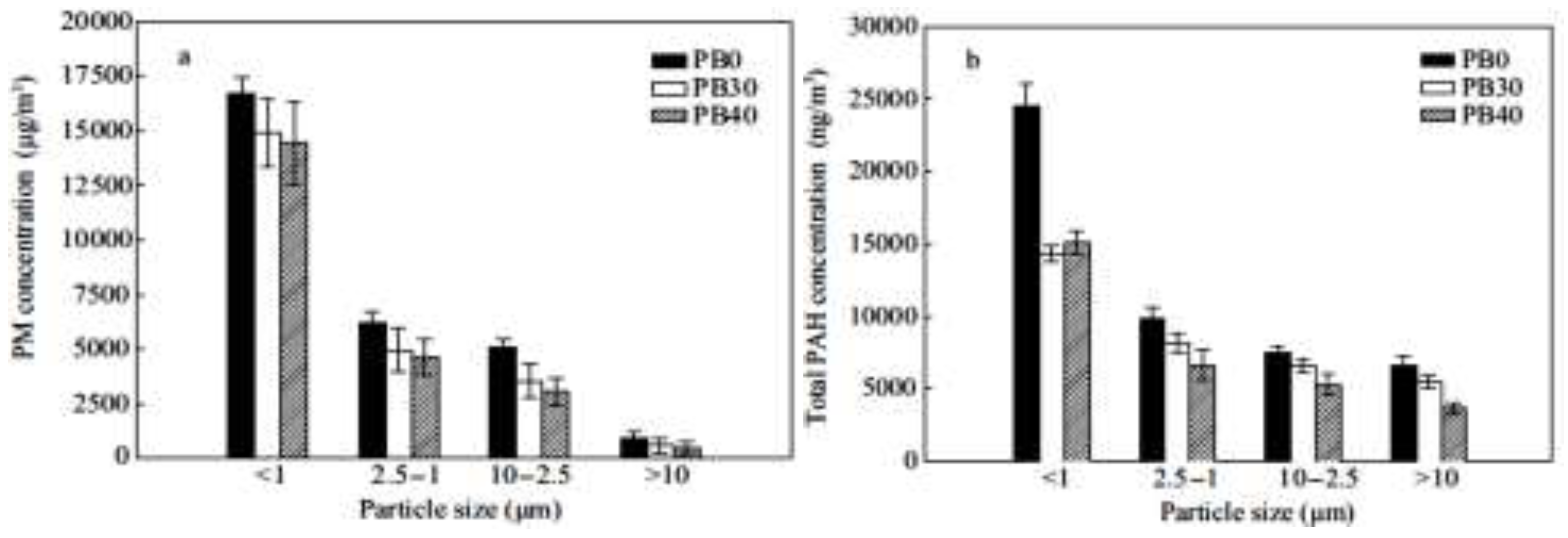
Figure 2.
Projected area against spray tip penetration [37].
Figure 2.
Projected area against spray tip penetration [37].
Figure 3.
The storage duration against viscosity and CO emission [20].
Figure 3.
The storage duration against viscosity and CO emission [20].
Figure 4.
SMD against different blends [40].
Figure 4.
SMD against different blends [40].
Figure 5.
Different grid sensitivity; (a) densest mesh and (b) less dense mesh [53].
Figure 5.
Different grid sensitivity; (a) densest mesh and (b) less dense mesh [53].
Figure 6.
Structure of a turbulent flow [54].
Figure 6.
Structure of a turbulent flow [54].
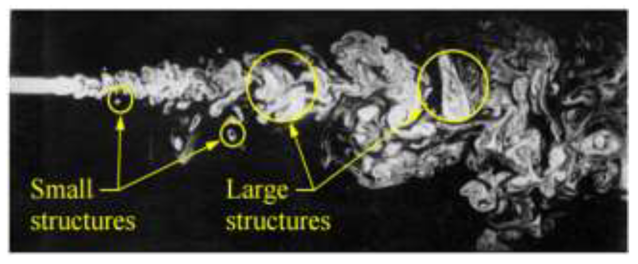
Figure 7.
Energy cascade [54].
Figure 7.
Energy cascade [54].
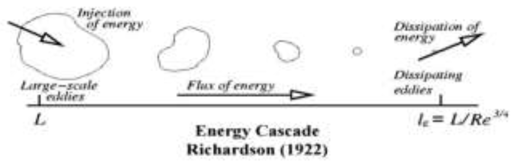
Figure 8.
Rapid mixing type injector [59].
Figure 8.
Rapid mixing type injector [59].
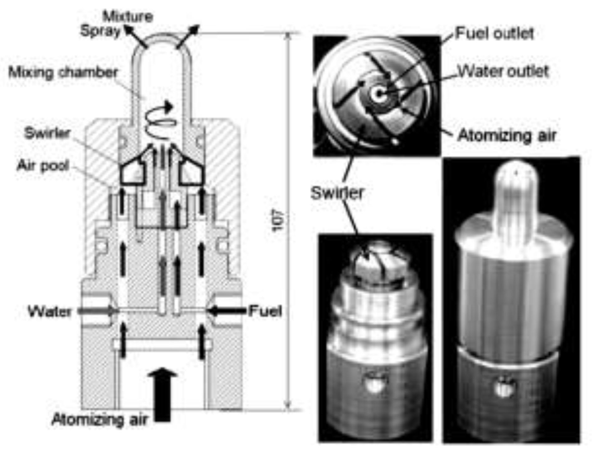
Figure 9.
Flow field and stream lines [71].
Figure 9.
Flow field and stream lines [71].
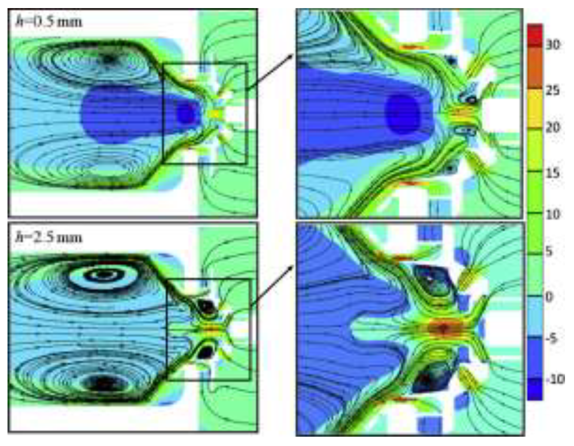
Figure 10.
Velocity vectors of (a) standard k – ε model, and (b) realizable k – ε model [74].
Figure 10.
Velocity vectors of (a) standard k – ε model, and (b) realizable k – ε model [74].
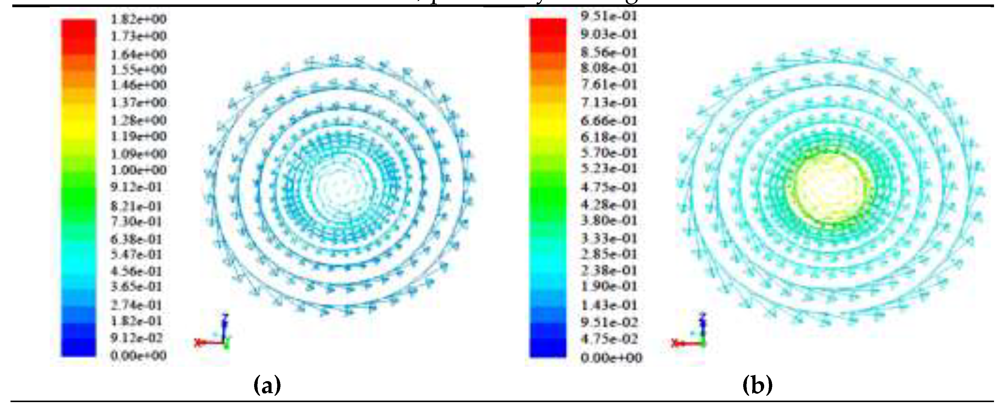
Figure 11.
Cavitation in a nozzle [76].
Figure 11.
Cavitation in a nozzle [76].
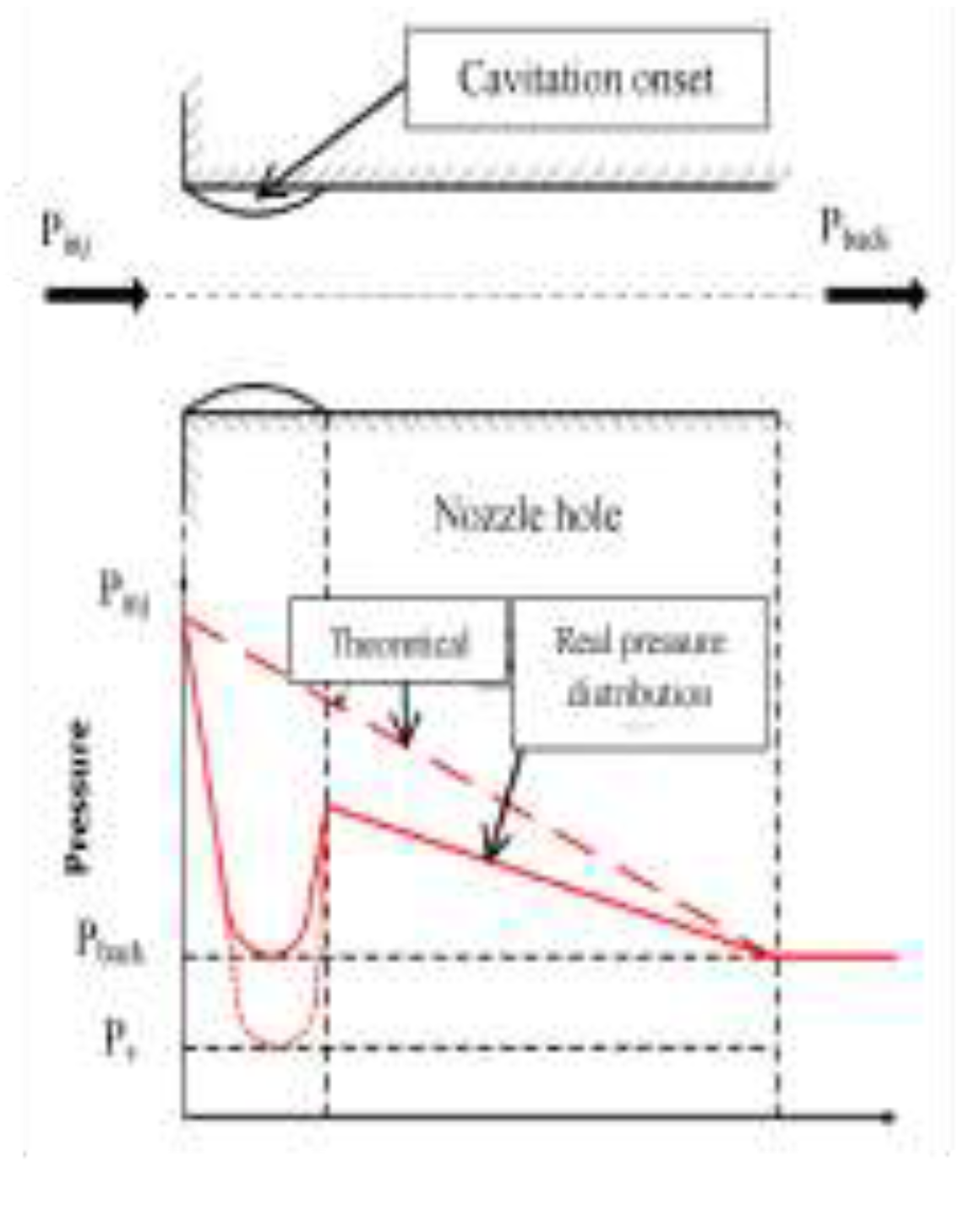
Figure 12.
Liquid velocity diameters with different L/D ratio (a) D = 3 mm and (b) D = 1.5 mm [85].
Figure 12.
Liquid velocity diameters with different L/D ratio (a) D = 3 mm and (b) D = 1.5 mm [85].
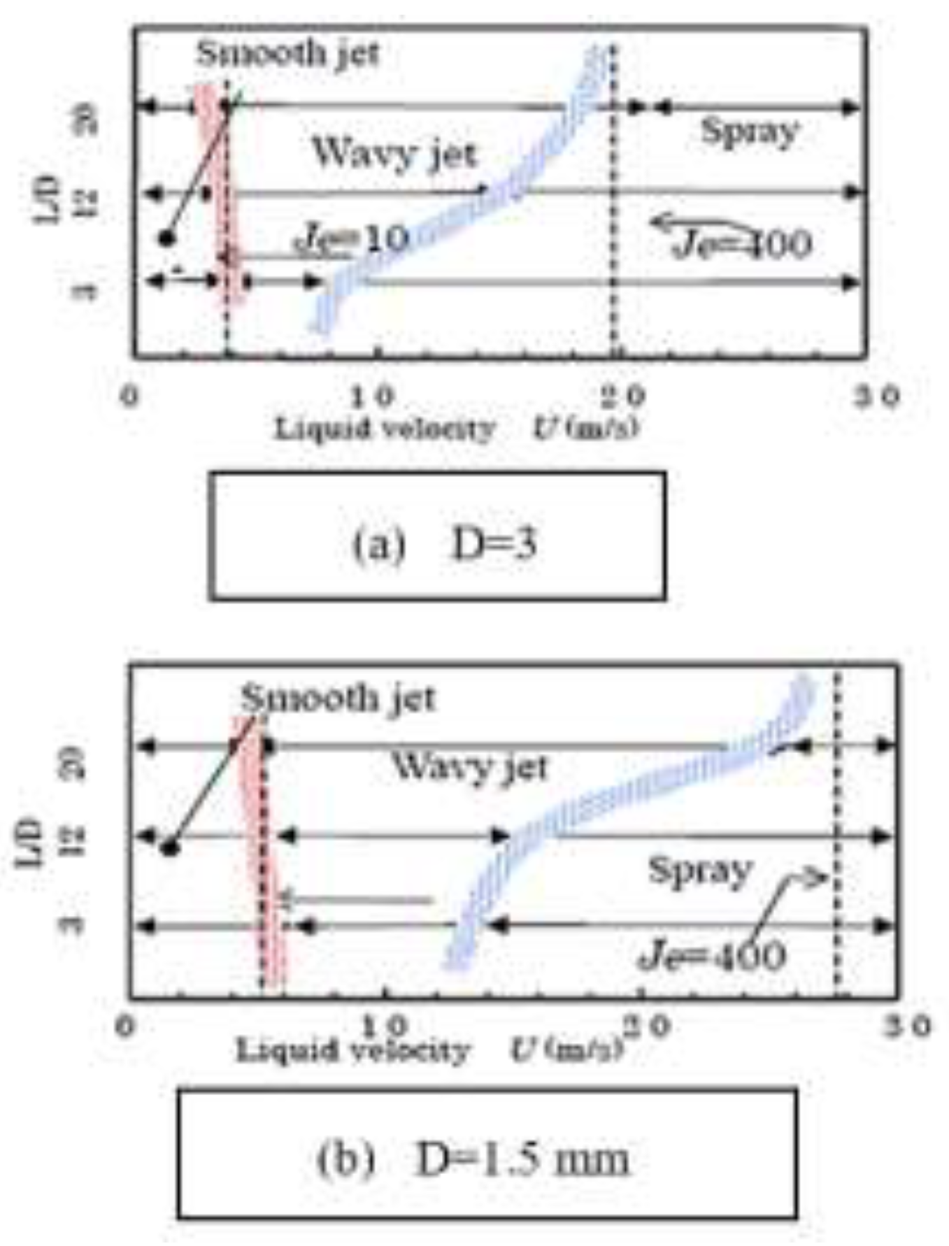
Figure 13.
Injection pressure against spray angle [86].
Figure 13.
Injection pressure against spray angle [86].
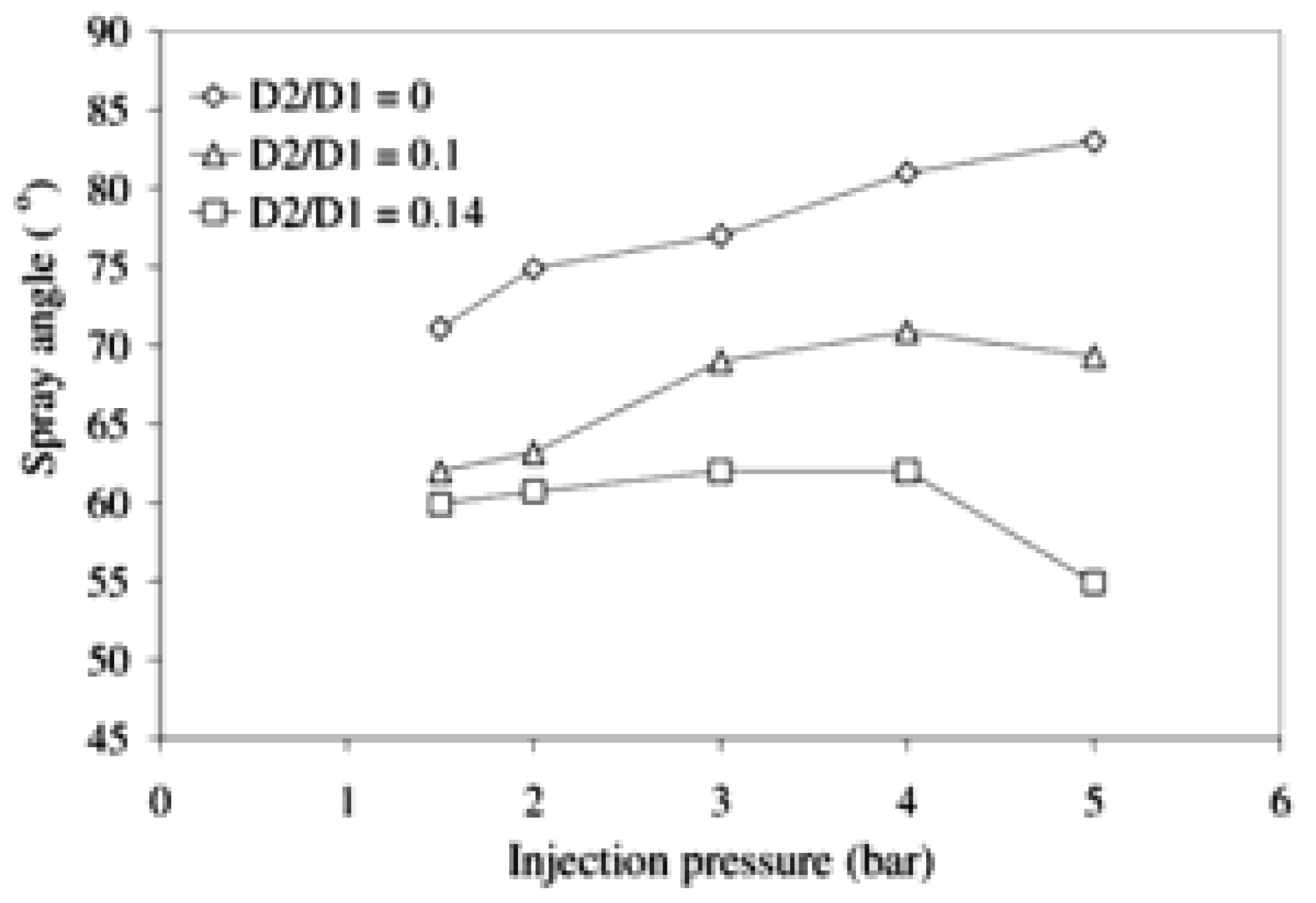
Figure 14.
Cylindrical nozzle [93].
Figure 14.
Cylindrical nozzle [93].
Figure 15.
Discharge coefficient against Reynolds number (Re) [81].
Figure 15.
Discharge coefficient against Reynolds number (Re) [81].
Figure 16.
The effects of flow rate on spray characteristics [84].
Figure 16.
The effects of flow rate on spray characteristics [84].
Figure 17.
3D spray flow distributions and droplets [55].
Figure 17.
3D spray flow distributions and droplets [55].
Figure 18.
Penetration length against biofuel blends [18].
Figure 18.
Penetration length against biofuel blends [18].
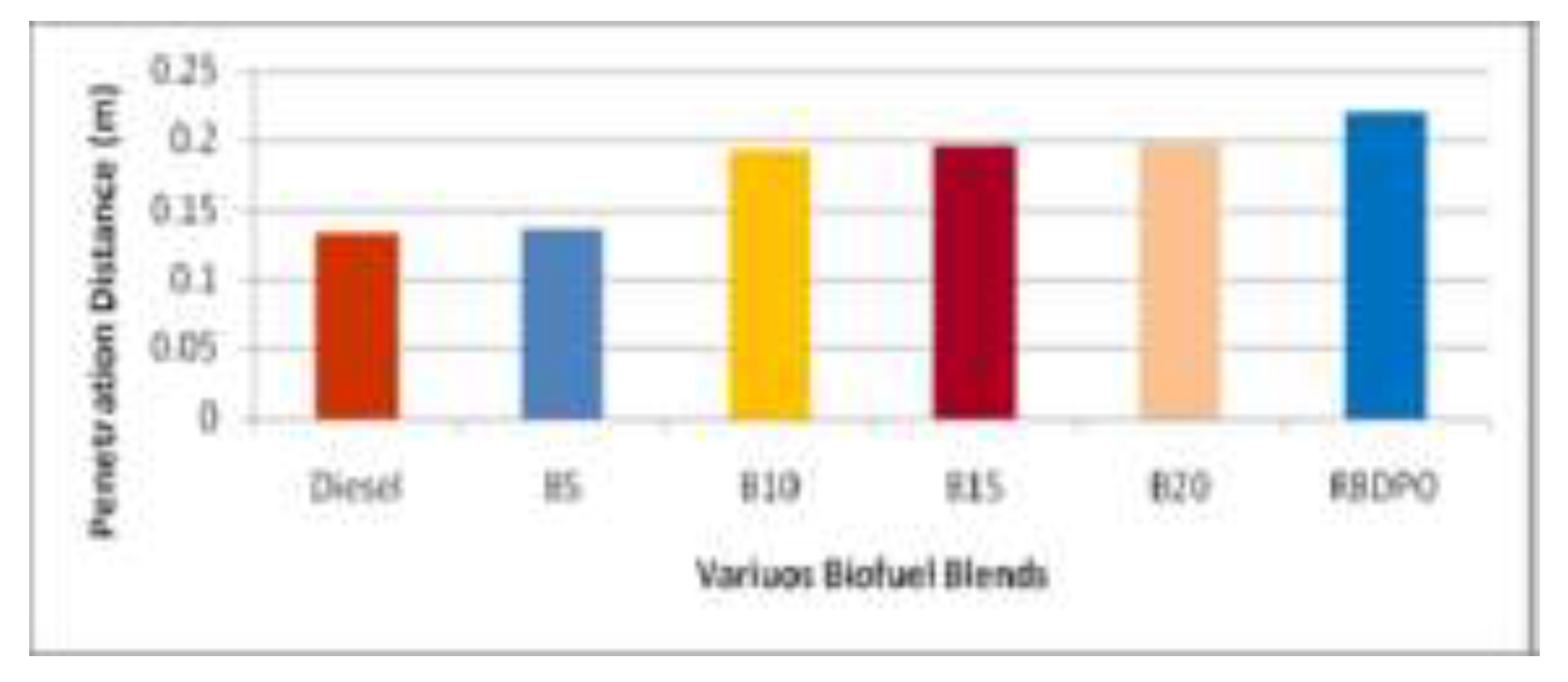
Figure 19.
Projected density distribution against transverse position [4].
Figure 19.
Projected density distribution against transverse position [4].
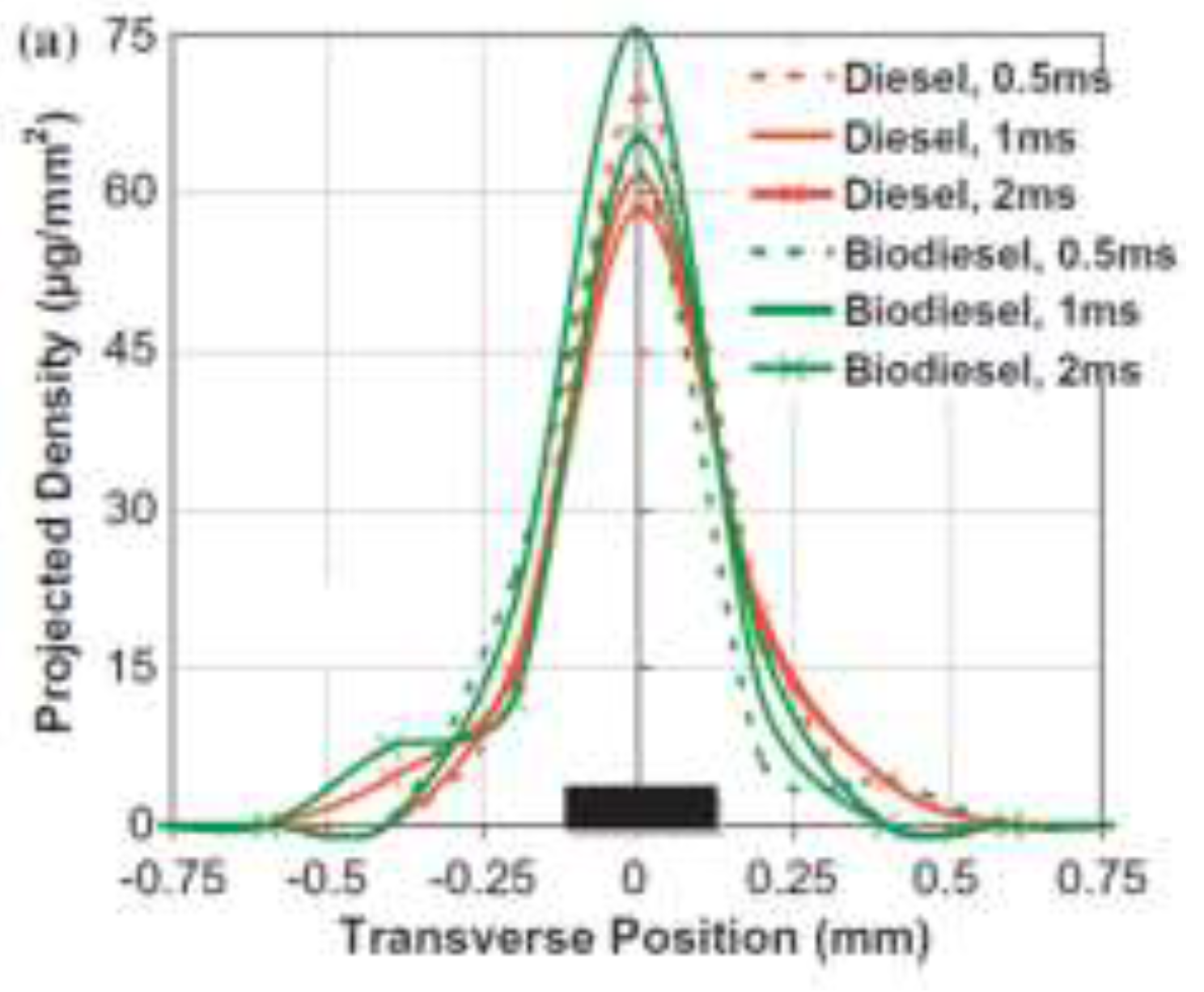
Figure 20.
Particles size versus various blends of biofuel [18].
Figure 20.
Particles size versus various blends of biofuel [18].
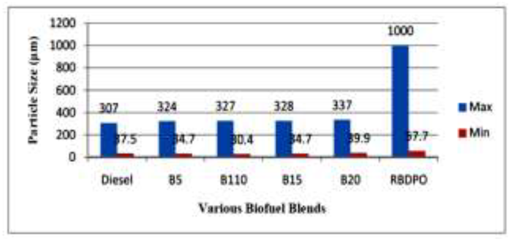
Figure 21.
A pattern of spray from a nozzle [86].
Figure 21.
A pattern of spray from a nozzle [86].
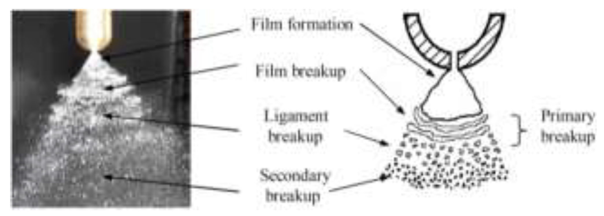
Figure 22.
Spray angle against time [96].
Figure 22.
Spray angle against time [96].
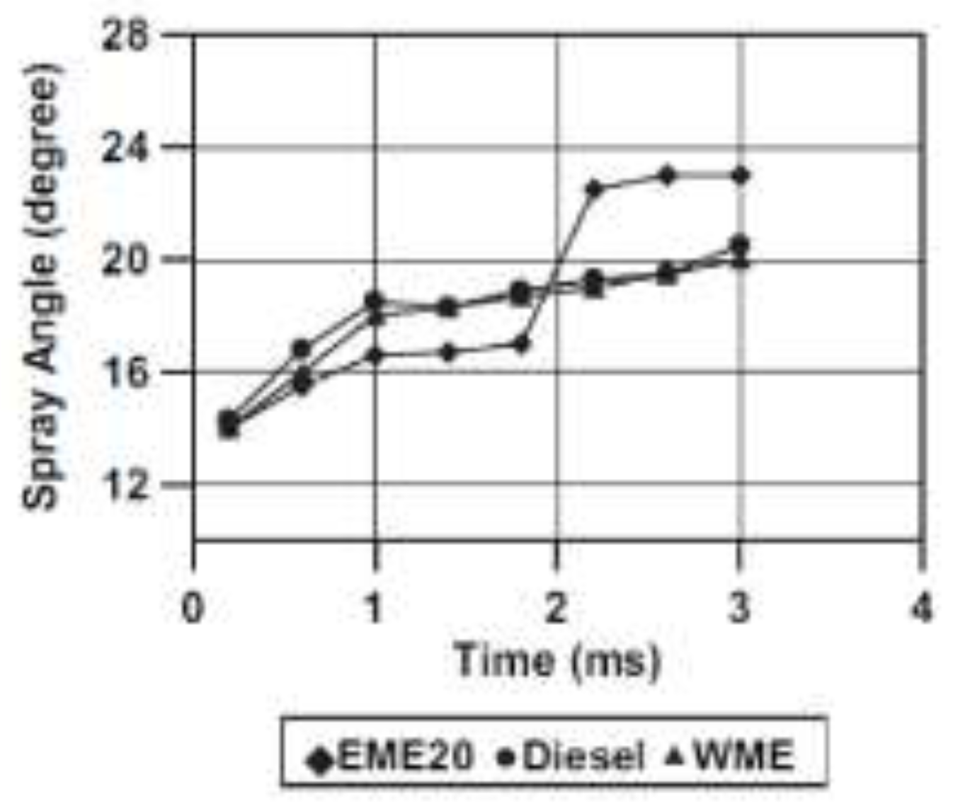
Figure 25.
SMD against different biodiesel blends of experimental and simulation results [18].
Figure 25.
SMD against different biodiesel blends of experimental and simulation results [18].
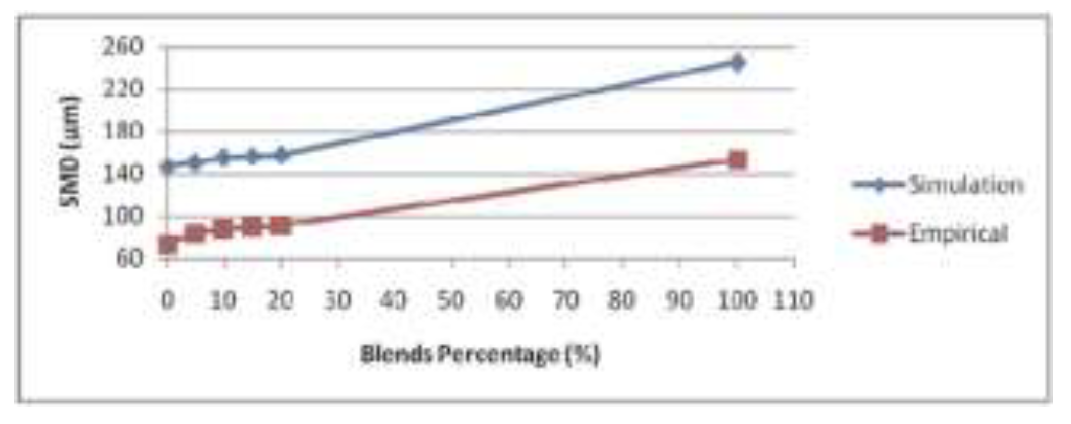
Figure 26.
Spray tip penetration versus time [5].
Figure 26.
Spray tip penetration versus time [5].
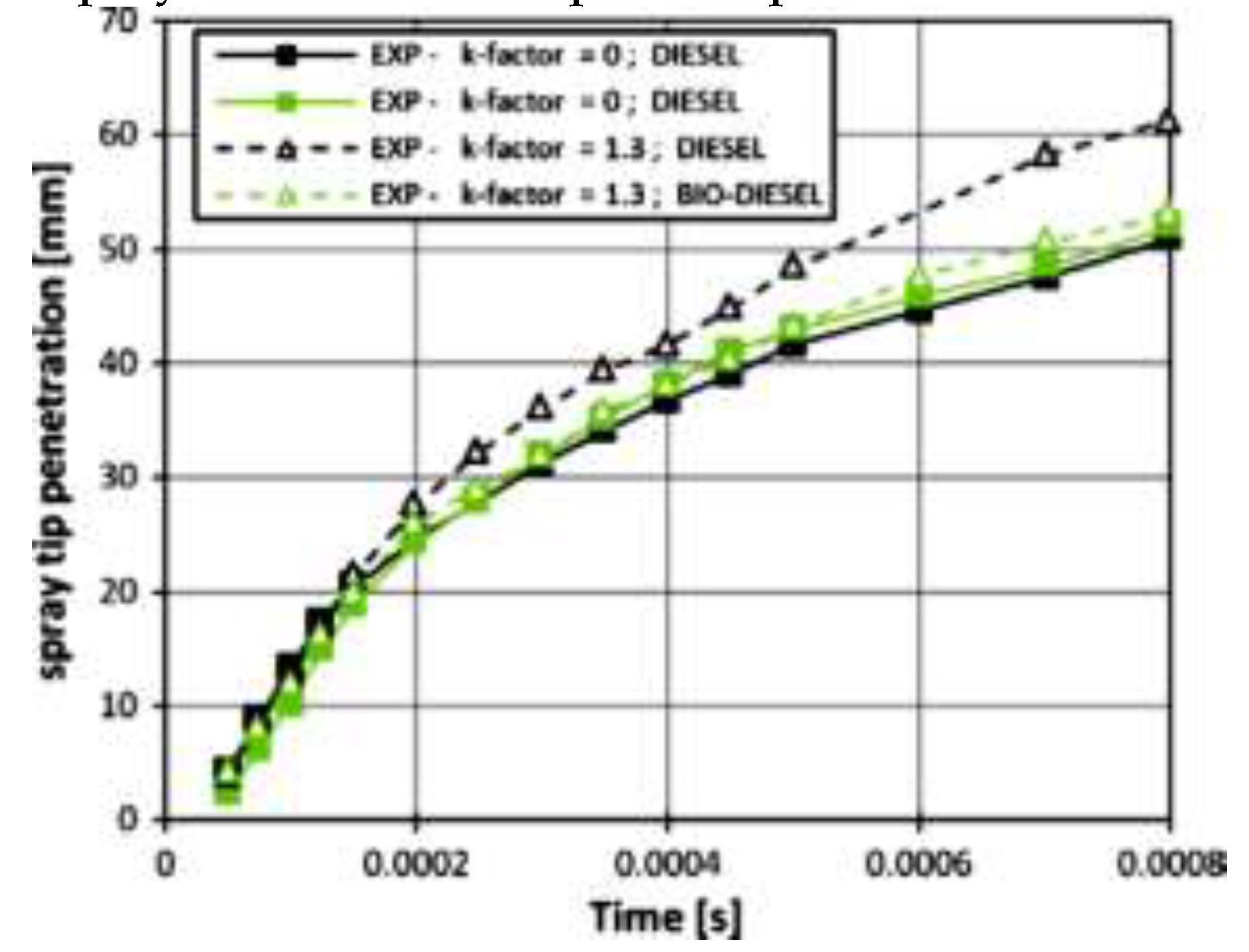
Figure 27.
Radial profiles (a) normalised D32, the (b) normalised V, and the (c) normalised Dρ [101].
Figure 27.
Radial profiles (a) normalised D32, the (b) normalised V, and the (c) normalised Dρ [101].
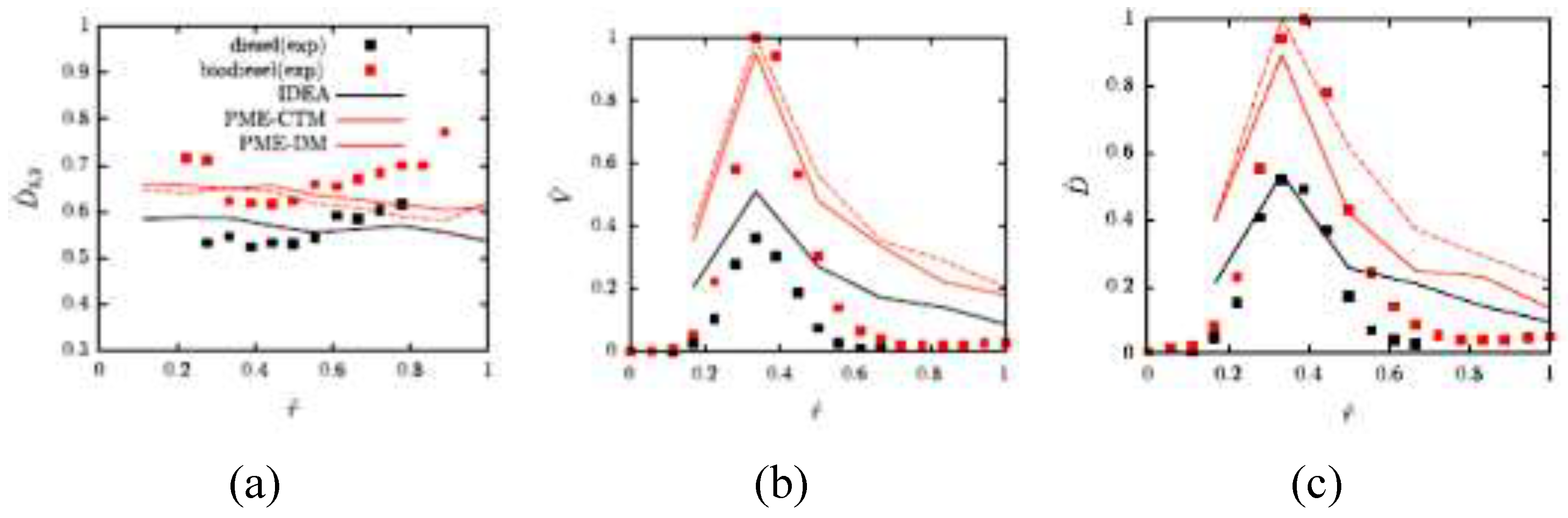
Disclaimer/Publisher’s Note: The statements, opinions and data contained in all publications are solely those of the individual author(s) and contributor(s) and not of MDPI and/or the editor(s). MDPI and/or the editor(s) disclaim responsibility for any injury to people or property resulting from any ideas, methods, instructions or products referred to in the content. |
© 2024 by the authors. Licensee MDPI, Basel, Switzerland. This article is an open access article distributed under the terms and conditions of the Creative Commons Attribution (CC BY) license (http://creativecommons.org/licenses/by/4.0/).
Copyright: This open access article is published under a Creative Commons CC BY 4.0 license, which permit the free download, distribution, and reuse, provided that the author and preprint are cited in any reuse.


