Submitted:
17 November 2024
Posted:
19 November 2024
You are already at the latest version
Abstract
RF signals are widely used in various applications such as telecommunications, wireless communication systems, and radar systems. These signals can be manipulated using phase shifters that adjust the signal's phase. This adjustment is essential for beam shaping, signal cancellation, and frequency synthesis in antenna arrays. By controlling the phase of the RF signal, phase shifters help manipulate electromagnetic waves for various applications. Therefore, as Gallo points out, phase shifters are essential for manipulating and controlling high-frequency signals. This manipulation and control is essential to improving the performance of wireless communication and radar systems and can improve signal reception and transmission.The study examines different types of phase shifters, conducts a comparative analysis of different phase shifter topologies and technologies, and highlights their respective advantages and limitations in applications. In addition, the review includes a specific study of liquid metal phase shifters. Finally, the article outlines future research directions for liquid metal phase shifters, It emphasizes the need for innovative design strategies to keep pace with the evolving wireless communications and telecommunications fields. Therefore, this article can serve as a reference for the milestones in RF phase shifter research.
Keywords:
1. Introduction
2. Methodology
2.1. Phase Shift’s Experimental Characterization
2.2. The principle of phase shift
2.2.1. Frequency Capability and Bandwidth
2.2.2. Insertion and Return Losses
2.2.3. Linearity
2.2.4. Resolution and Phase Range
2.2.5. Power Handling
2.2.6. Amplitude and Phase Errors
2.2.7. Surface area
2.2.8. Power Consumption
3. Related Work
3.1. Phase Shifters - Definition
- Definition 1:A phase shifter is a transformer-based device that regulates the phase angle of voltage in a power system. The phase shifter regulates power flow across a power line by shifting the phase of terminal voltage phases [15]. Phase shifters play a crucial role in microwave systems, including phase modulators, frequency up-converters, and phased arrays. They enable adaptive beam shaping and steering [16].
- Definition 2:. Phase shifters can be defined as two-port passive microwave devices that allows for the adjustable phase changing of the incoming RF signal at the output port. Both the input and output ports should have perfect impedance matching to result, ideally, attenuating the outgoing signal at zero. These approximations are realized by proper design criteria to obtain the best performance [17].
-
Definition 3: Phase shifters are the major building blocks of “phase array antenna” systems. They are mostly employed in the back of transmitter antennas to electronically steer the antenna beams. Two-port lossless phase shifters are used. From input to output, they change the transmission phase. The transfer scattering parameter’s phase (w), describes the phase shift and is measured by [18]:
- Definition 4:A phase shifter is a transformer-based device, of which the essential feature is to regulate a phase-angle of a voltage in a power system. Changing the phase shift between terminal voltage phasors, the phase shifter regulates power flow through a power line. This feature of the phase shifters may be used to overcome problems with loop flow in a power system. These undesirable power flows cause increasing power losses and by that reduce the transmission capability of power lines. The phase shifters redirect power flows in a power system, which can improve the stability of this system [19].
3.2. Phase shifters as key components in phased array systems
- mmWave phase shift 0-360° or 0-180° without exceeding insertion loss limits .
- The insertion loss variation over the entire phase shift range over the desired frequency band is small, i.e., h. The insertion loss variation with bias control is small. This is done to minimize beam distortion during steering. Since signal combining and nulling in undesirable directions are significantly affected by the signal amplitude in each channel, the phase shifter must not only have low insertion loss, but also maintain constant loss over its phase tuning range.
- High phase shift resolution.
- Control is facilitated by factors such as low frequency bias, along with a linear phase shift-voltage response and minimal power consumption, exemplified by a bias voltage of less than 10V.
- Fast response.
- Robust, reliable (for instance, capable of functioning in humid conditions and varying temperatures).
- High power handling capacity (needed for high-power, low-loss transmitters).
- Compact for being inserted.
3.3. Topologies of Phase Shifters
- Transmission Line Phase Shifters
- Ferrite Phase Shifters
- Reflective Load Phase Shifter (RTPS)
- Hybrid Coupler Phase Shifters
- Semiconductor Phase Shifters
- Digital Phase Shifters
3.4. Types of Phase Shifters
3.4.1. Digital phase shifters
-
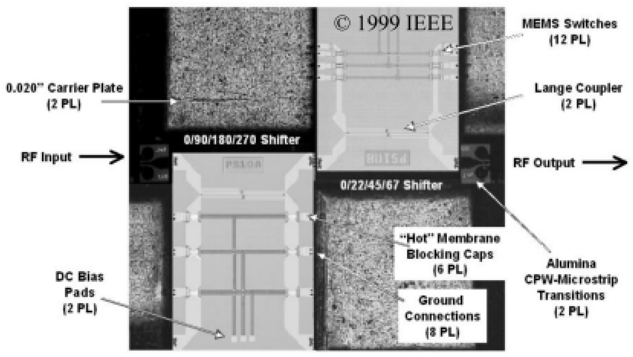
Microelectromechanical systems (MEMS):The primary feature of MEMS is its ability to perform electrical and mechanical activities. Their architecture is mechanically flexible and/or moveable in response to pressure, electrostatic, thermal, piezoelectric, or magnetic pressure. Electrostatic control is the most commonly utilized actuation method in microwave applications. Switches and radio frequency variable capacitors are the two main applications being pursued. Both of these devices operate on the same concept [19,21], and were applied to achieve the state switching of the phase shifter, as Figure 2 shows:Figure 2. Photograph of assembled 4-bit MEMS phase shifter circuit [22]Figure 2. Photograph of assembled 4-bit MEMS phase shifter circuit [22]
 There are numerous approaches(topologies) available for implementing RF MEMS digital phase shifters, as Figure 3 illustrates:Figure 3. The schematic layouts of (a) switched-line, (b) loaded-line, (c) reflection, and (d) distributed-line RF MEMS phase shifter design implementations. SPDT: single-pole double-throw[17] .Figure 3. The schematic layouts of (a) switched-line, (b) loaded-line, (c) reflection, and (d) distributed-line RF MEMS phase shifter design implementations. SPDT: single-pole double-throw[17] .
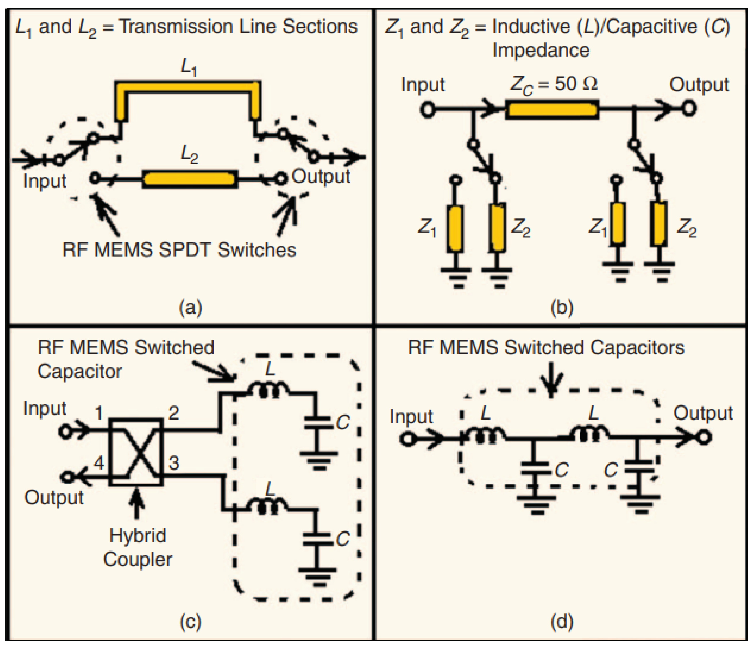
-
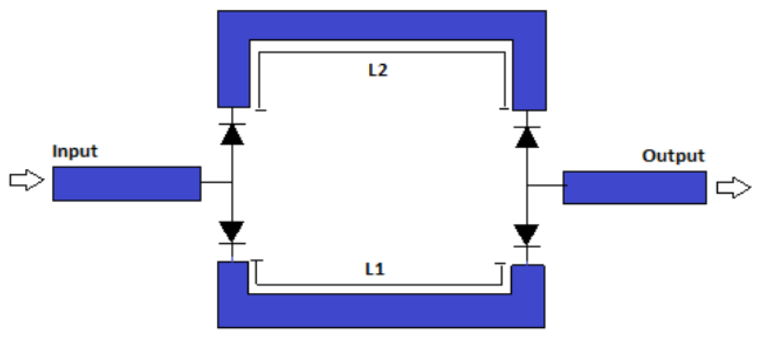
Switched line phase shifters: In terms of approach and design criteria, switching-line implementation is the simplest of all phase shifters. Their losses are comparable to the aggregate losses of switches and lines. This type of phase shifter can be built utilizing SPNTs (Single Pole N Throw) in either series or parallel mode. In Ka-band, 90° and 180° phase shifters with phase delay lines were constructed [23,24]. Figure 4 illustrates the simplest version of SLPS, which uses four Single Pole Single Throw (SPST) switches to transmit signals between two transmission lines of varying lengths. The equation 8 gives the differential phase shift between the two trajectories.Figure 4. Basic schematic of a switched line phase shifter [23]Figure 4. Basic schematic of a switched line phase shifter [23]
 The schematic layout of a standard RF MEMS three-bit switched-line phase shifter with a MEMS series switch is shown in Figure 5, The sequence shows three separate sections (bits) that each produces phase shifts of 30°, 60°, and 120°, cascading linearly. Each section (bit) comprises a delay line (generating the required amount of 30°, 60°, or 120° phase shift) and the reference line (of 0° phase shift), with switching elements in both the delay and reference lines. This makes it possible to select each transmission line section separately to achieve a specified phase shift value at the output; for instance, to generate a 90° phase shift, To achieve a 180° phase shift, it is necessary to select the first and second bits, and the second and third bits are also necessary [17]:Figure 5. The schematic layout of the switched-line phase shifter [17]Figure 5. The schematic layout of the switched-line phase shifter [17]
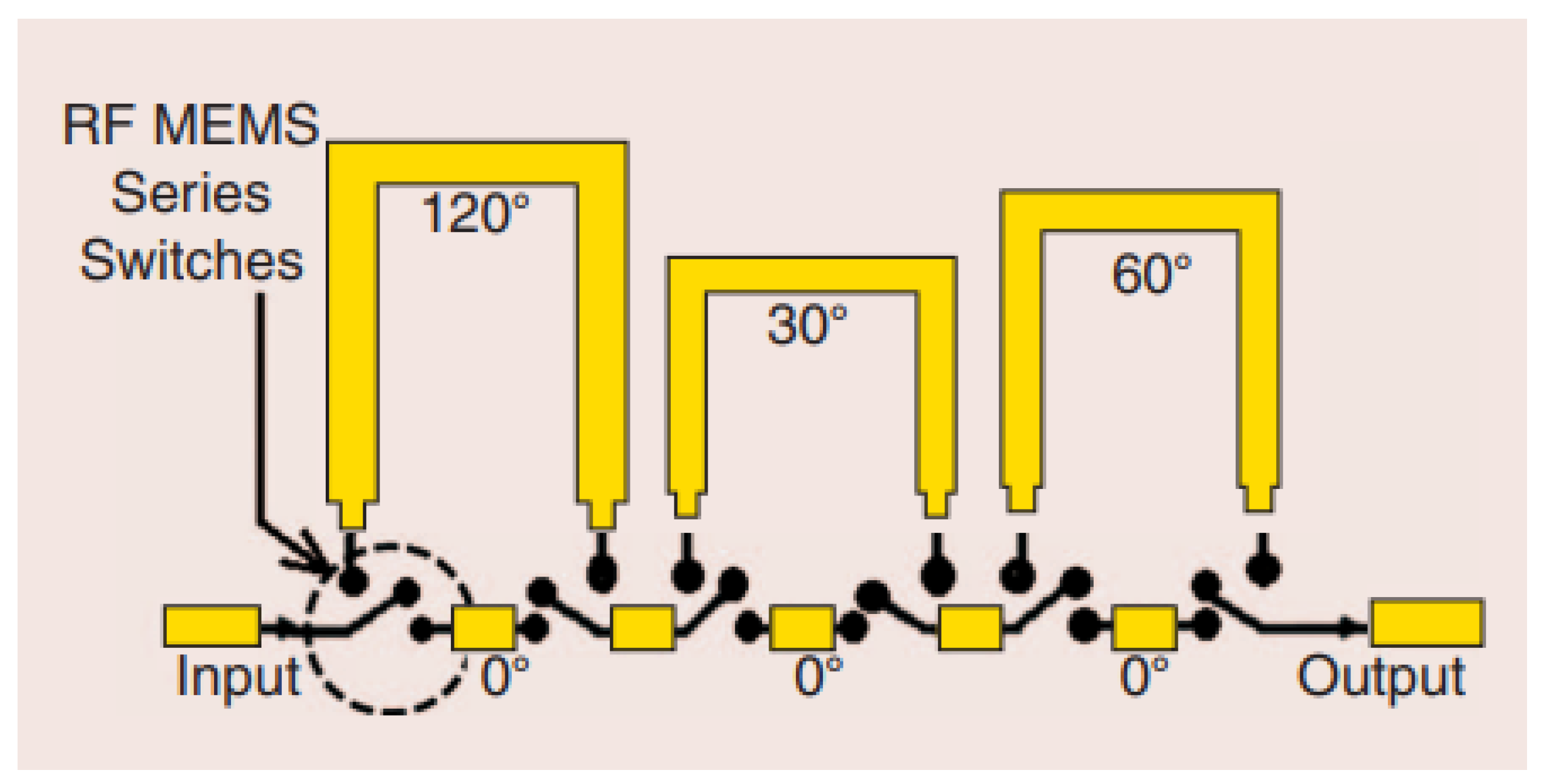
-
Loaded line phase shifters: The idea of loaded-line phase shifters dates back to the early 1960s and has been described in several research publications [25,26,27]. Both digital and analog phase shifters can be realized by employing the loaded-line technique, which is similar to the switched-line method. The phase shift mechanism of this circuit is based on a transmission line with a low reactance. More specifically, the plan is to load a line with two distinct impedances. A central line segment connecting the two networks may be utilized as a matching network to maintain input and output impedances close to 50 , as shown in Figure 6.Figure 6. The basic schematic of the loaded-line phase shifter [25]Figure 6. The basic schematic of the loaded-line phase shifter [25]
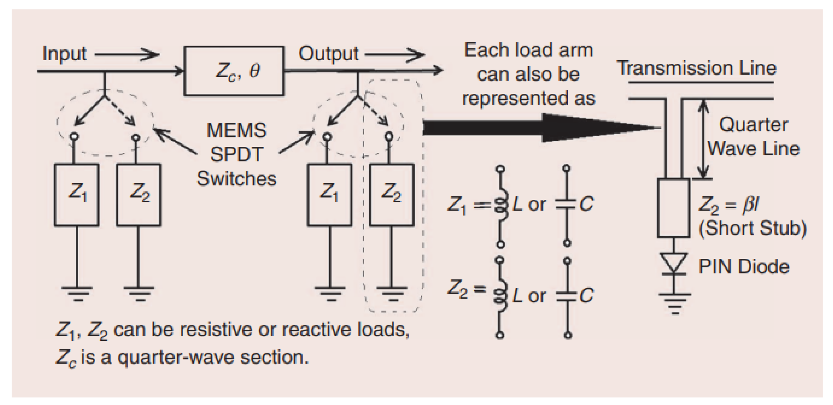 Radial stubs are used in microstrip technology to connect to MEMS switches located at regular intervals along the line. The phase shift occurs as a result of their simultaneous switching [25].Figure 7 represents the simulation model for a switched line with a loaded line. The long path has two tuning stubs (equivalent to a loaded line) at each corner, and the short path has one in the middle. To adjust the phase shift, simply change the length of the stubs.Figure 7. Simulation model of switched-line with loaded-line [25]Figure 7. Simulation model of switched-line with loaded-line [25]
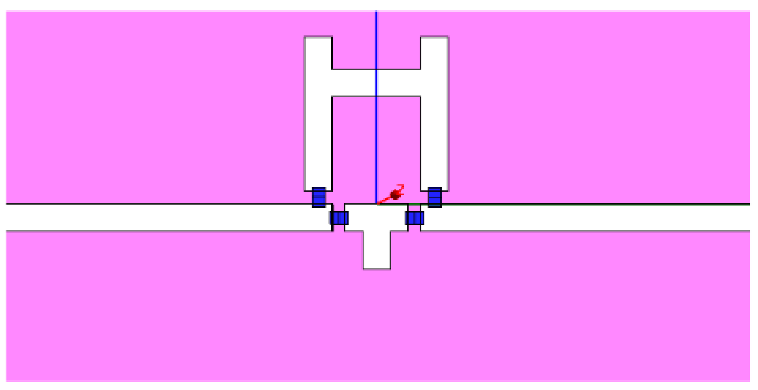
-
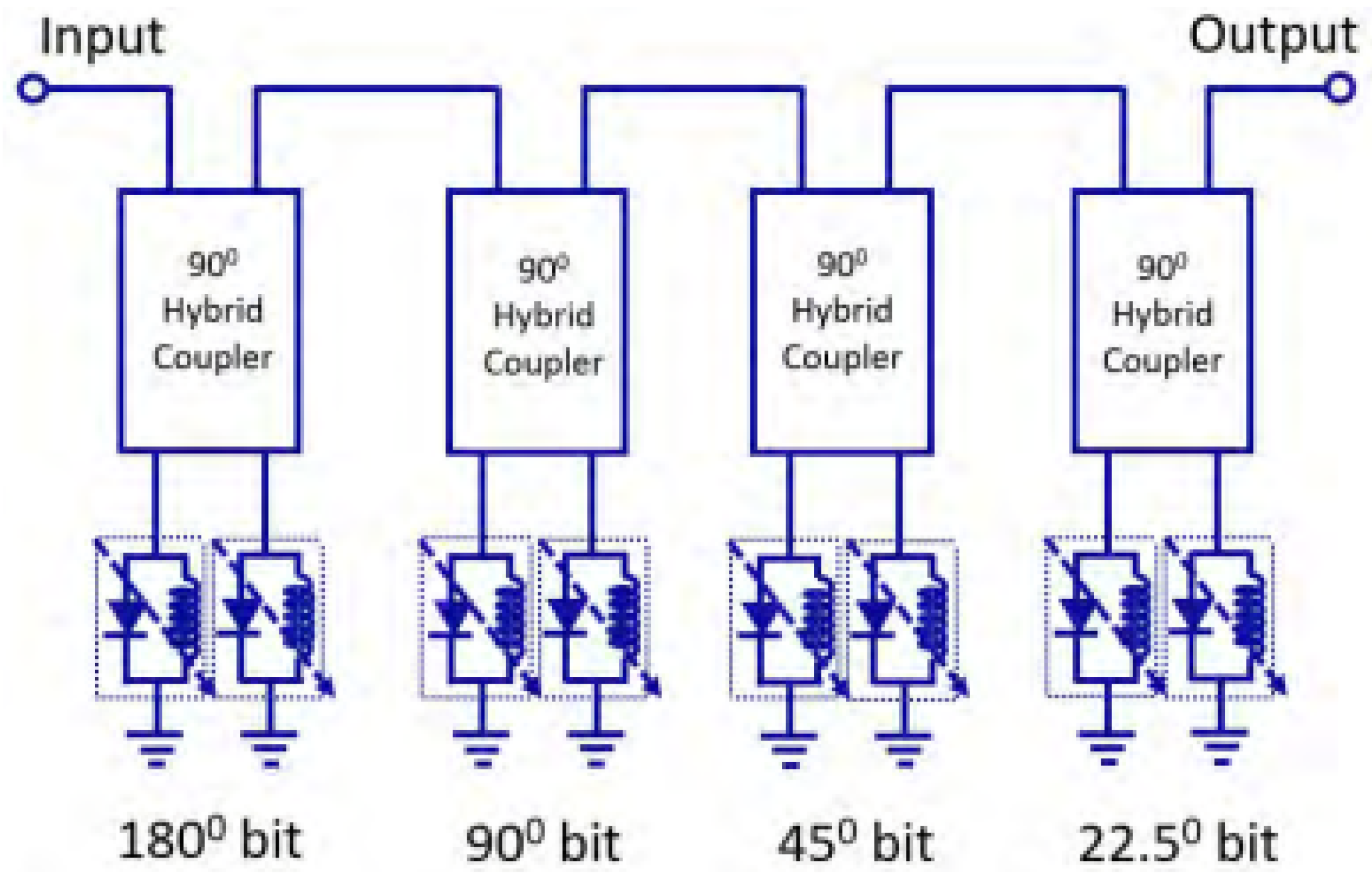
Reflection Phase Shifters: Similar to the earlier examples, digital and analog versions of RF MEMS-based reflection-type phase shifters can be built; however, the analog format is not commonly employed due to its complex design. Reflection phase shifters employ 3-dB hybrid couplers as one of their main components, in contrast to the previously documented switched-line and loaded-line phase shifter implementations.Figure 8. Schematic diagram of a reflection-type phase shifter [28]Figure 8. Schematic diagram of a reflection-type phase shifter [28]
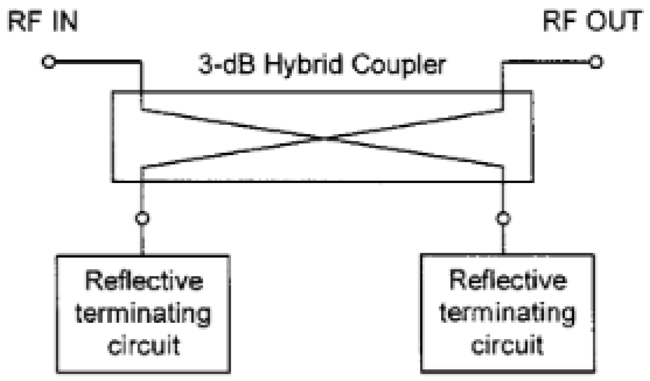 Figure 9(a) and (b) demonstrate two distinct approaches for implementing the reflection-type N-bit phase shifter, both of which use a sequence (say, "N") of MEMS series or shunt switches on a transmission line.Figure 9. Schematic diagram of a reflection-type phase shifter [28]Figure 9. Schematic diagram of a reflection-type phase shifter [28]
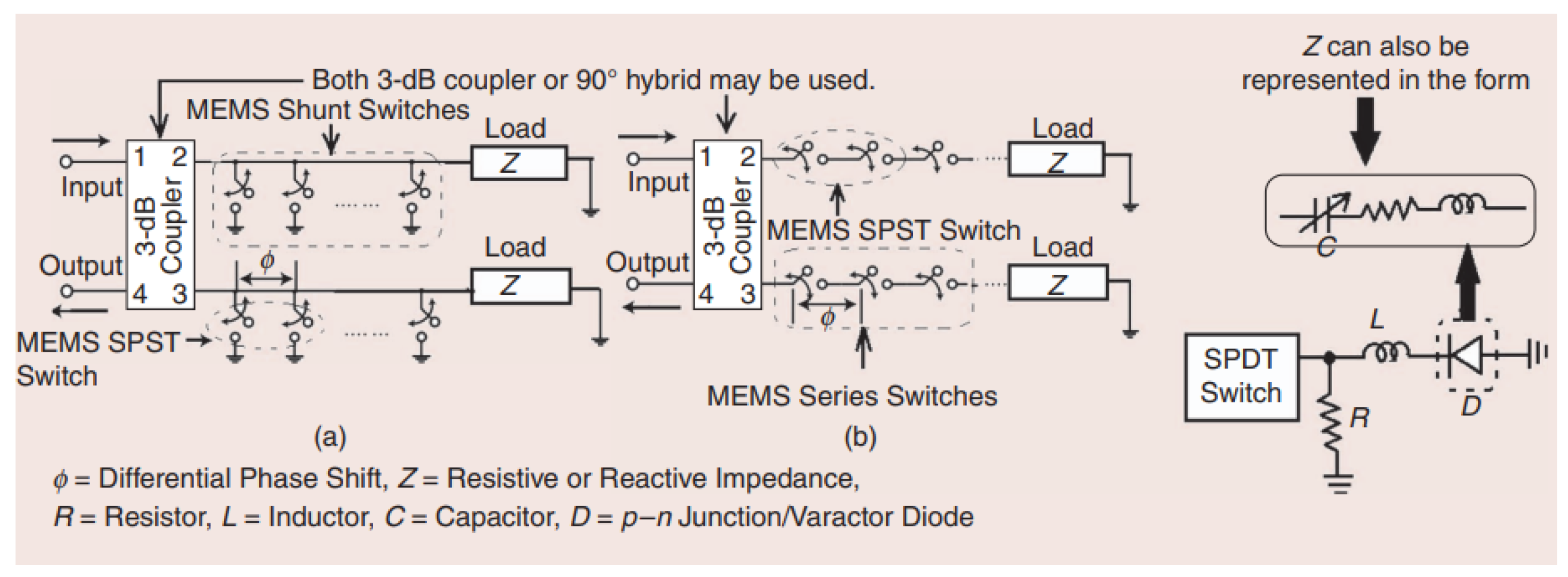
- Based Distributed-Line Phase Shifters: The most popular among all RF MEMS-based phase shifters is distributed-line phase shifters, or rather, distributed MEMS transmission line (DMTL) phase shifters. This category encompasses the majority of studies that relate to MEMS-based phase shifter designs, and they are still in the process of being researched. The principle of their operation is that a transmission line, like a CPW or microstrip line, is loaded by passive components, like switched capacitors or varactors, periodically.
-
- Transistors: In [29,30], transistors were used as switches, while resistors and capacitors were used to create the phase-shifting function. Compared to passive designs, active phase shifters [31], where differential phases are obtained by the roles of transistors rather than passive networks, can achieve a high integration level with decent gain and accuracy, as well as fine digital phase control under a constrained power budget.
- PIN diodes: These are commonly used in digital phase shifters to control signal phase shift. To adjust the conductivity of a digital phase shifter, the PIN diode is biased in either the forward or reverse direction. When the PIN diode is forward-biased, it acts as a low-resistance switch and permits current to pass through it. When the diode is reverse-biased, it has a high impedance and functions as an open switch. Phase shifters make use of numerous PIN diodes to create discrete phase shifts. Each PIN diode has a unique control signal that affects its biasing status. The phase shift can be regulated in discrete stages by using enabled diodes. In the proposed design [32], as shown in Figure 10, the PIN diode was modeled as separate components representing forward and reverse states. Loads were produced utilizing a single inductor coupled in parallel with PIN diodes, eliminating the need for high-isolation diodes.Figure 10. Configuration of 4-bit PIN diode reflection-type phase shifter [32]Figure 10. Configuration of 4-bit PIN diode reflection-type phase shifter [32]
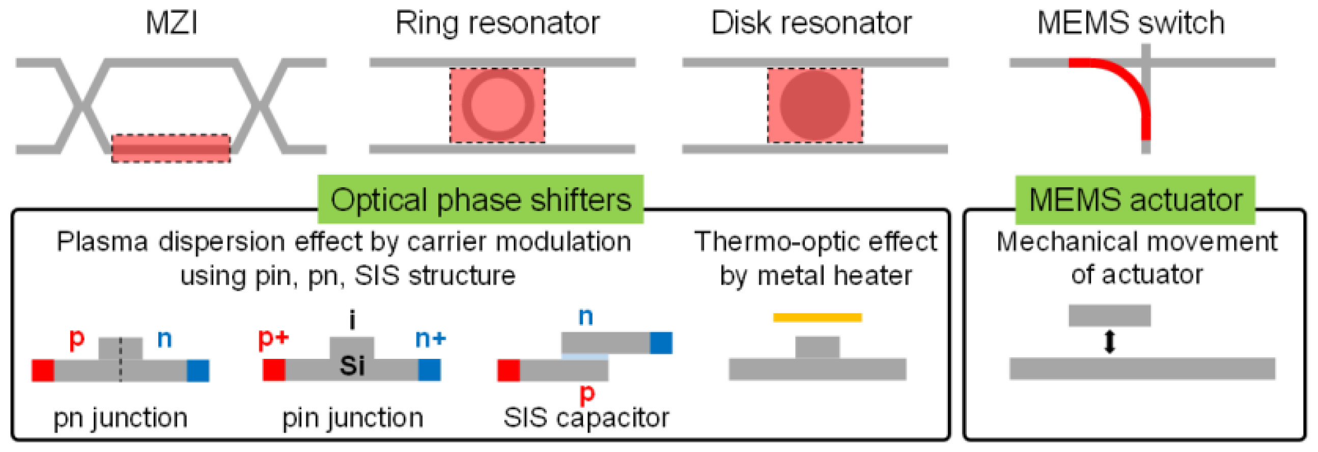
3.4.2. Optical phase shifters
3.4.3. Analog phase shifters
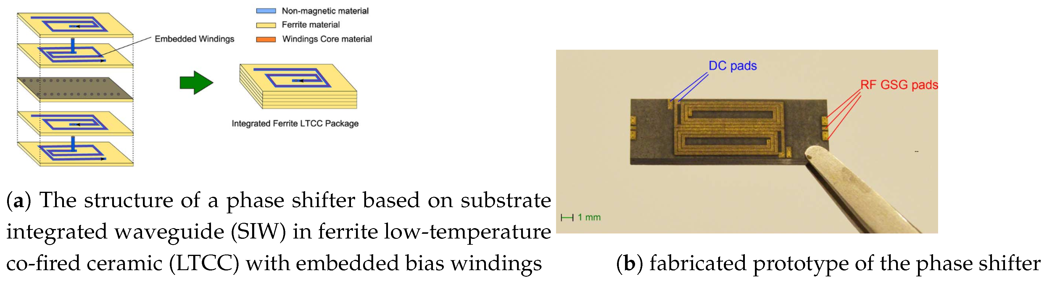
- Ferrite phase shifters: These traditional analog phase shifters use ferrite materials’ magnetic characteristics to produce phase shifting. Ferrite phase shifters work on the Faraday effect and the interaction of a magnetic field with a microwave signal [40,41]. Ferrite phase shifters have been used in microwave power applications for over two decades, providing fine phase control at moderate to high levels. However, this form of phase shifter is typically big and consumes a significant amount of power, making it unsuitable for compact and affordable microwave systems. Ferrite phase shifters have been used for over two decades in applications that require accurate phase control at moderate to high microwave power levels. However, this form of phase shifter is typically big and consumes a significant amount of power, making it unsuitable for compact and affordable microwave systems. Figure 12 represents a conventional ferrite phase shifter, as reported in [42].Figure 12. A typical ferrite phase shifter [42]Figure 12. A typical ferrite phase shifter [42]
-
Electronic components include phase shifters: Phase shifters use solid-state electrical components to modulate signals and control the phase shift. They are less expensive to operate since they do not require costly digital gear in the network. As a result, a large amount of research and development has been focused on phase shifters to enable low-cost and downsized microwave systems [17]. The phase shift of electronic components, including PIN diodes [42] [17], varactors [43,44], tunable inductors, transistors, and MEMS devices, can be modified within a specific range by adjusting the voltage applied to them [44,45,46,47,48].
- Typically, PIN diodes function as switches, maintaining two distinct states: ’ON’ and ’OFF’ , which create a phase difference. Consequently, in phase shifter units that solely utilize PIN diodes for control, the phase shift values are generally predetermined and limited to specific increments [49]. In a previous study [50], researchers utilized a phase shifter that incorporated a series of interconnected reconfigurable defected microstrip structure (DMS) units. These units were created by introducing a slot into a microstrip line and connecting it with PIN diodes. Through the manipulation of the PIN diodes, switching between the ’ON’ and ’OFF’ states, the DMS units were able to modify the current paths and produce desired phase shifts.
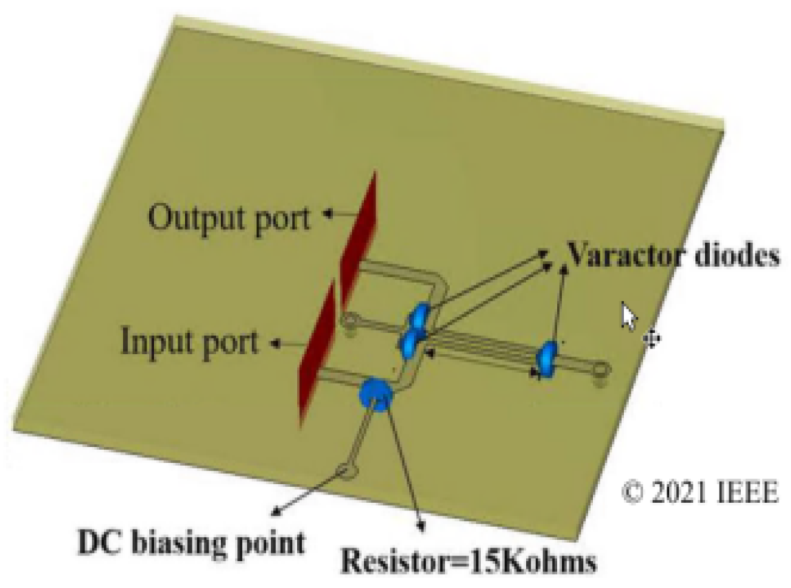
- With varactor diodes, phase shifters can continually tune the phase shift by continuously adjusting the capacitance, in contrast to phase shifters controlled by PIN diodes that have discrete and fixed phase shift values. An example of a tiny analog phase shifter that was utilized to accomplish a continuous transmission phase ranging from 0°to 180° was a varactor diode-based coupled-line construction [44]. Figure 13 shows the structure of this tiny analog phase shifter. It was comprised of two parallel coupling lines of identical length, joined directly at one end and loaded with a varactor diode and a short-circuited stub. Two varactor diodes were connected in series between parallel coupled lines and grounded via a microstrip line and a via hole. This phase shifter was tested to keep its insertion loss between 0.95 and 1.35 dB at 5.6 GHz, and it consistently achieved less than 3 dB insertion loss between 5.35 and 6.32 GHz.Figure 13. Schematic of a compact 180° analog phase shifter[49]Figure 13. Schematic of a compact 180° analog phase shifter[49]
- High power levels are achievable thanks to tunable inductor-based phase shifters. These phase shifters have minimal insertion loss, strong linearity, and a wide phase adjustment range. Additionally, they offer more consistent performance over temperature changes than other options because they are less affected by temperature fluctuations.
- The advantages of RF MEMS switches, such as low insertion loss, high linearity, wide bandwidth, fast switching speed, and high power handling capabilities, have made them a popular alternative to PIN diodes, FETs, and complimentary metal-oxide-semiconductor (CMOS) transistors [49].
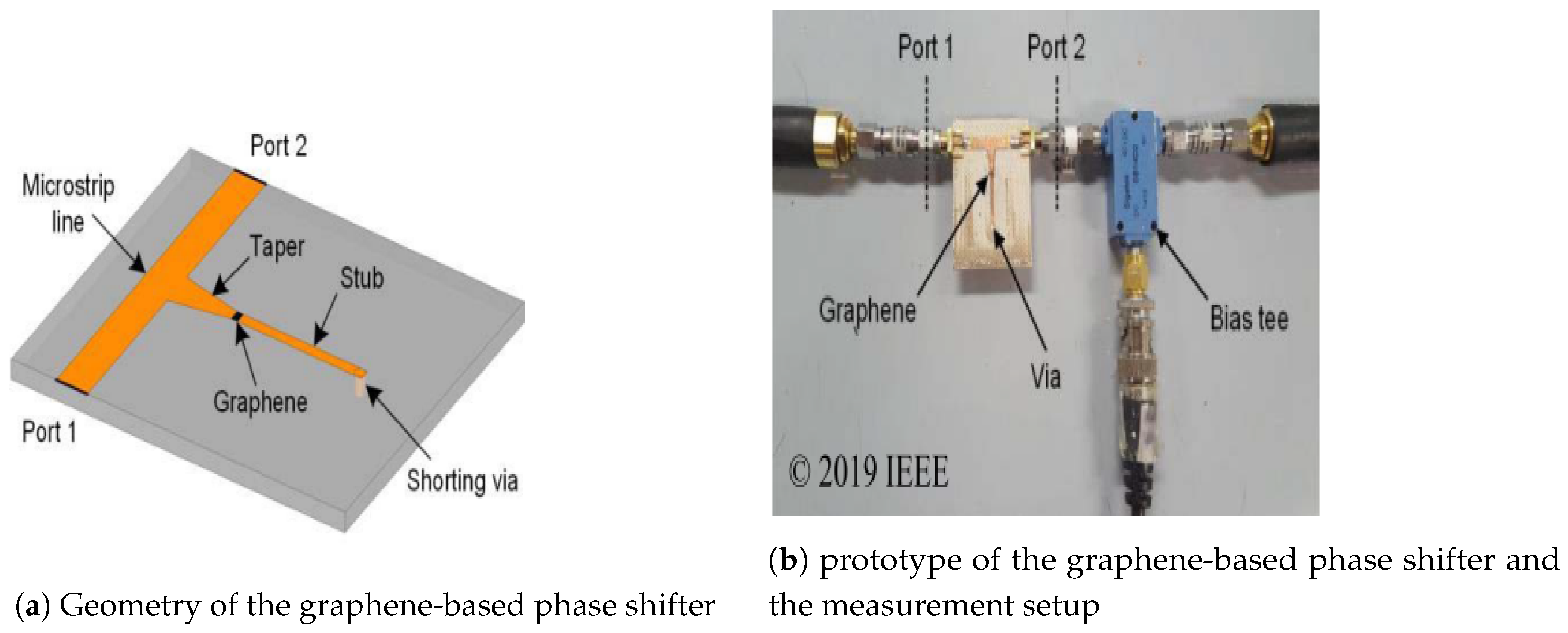
- Other type of analog phase shifters: Analog phase shifters can also use novel materials like graphene [50] or [44]. In [51], a graphene-based phase shifter achieved a maximum phase shift of 40 °within the 5 to 6 GHz range, with an insertion loss of 3 dB (see Figure 14). Because of the non-toxicity of gallium-based liquid metals such as Galinstan® and EGaIn, there has been a renaissance of research into liquid metal applications, particularly in the last 10-15 years. Some of the applications pursued by researchers (as outlined in the literature review) include reconfigurable antennas, stretchy antennas, strain, pressure sensors, and more [51].Figure 14. A typical graphene-based phase shifter
4. Comparative Studies
- •
- Mercury: Mercury has been discovered in Egyptian tombs dating back to 1500 BC [62], Mexican pyramids from 1800 years ago, and ancient Chinese and Tibetan histories [51]. While it is impossible to identify exactly what it was used for back then, it has modern applications in dentistry, lighting, gauges, mining, and electronics, to mention a few.
- •
- Gallium: Gallium is not a liquid metal at ambient temperature, like mercury, but its melting point is low enough (29.76 °C [85.58 °F]) to melt in a human hand and refreeze when removed [63]. When combined with other metals, some gallium alloys can have melting points as low as -19 °C (-2 °F) [63,63]. Since its discovery in 1875, gallium arsenide (GaAs) and gallium nitride (GaN) have been widely employed in electronics, particularly semiconductors. However, due to their non-toxicity, gallium liquid metal alloys have lately been employed as a replacement metal for a variety of mercury applications, including the thermometer [64].
5. Applications
-
Advanced Optical Computing Systems: Traditional computers built on the von Neumann architecture, which physically divides the processing module from the storage module, are encountering speed and integration density limits in the post-Moore era. To overcome Moore’s Law’s constraints, many scientists started investigating the upcoming generation of computer architectures and presented some intriguing computing platforms. we find two types:
- -
- Neuromorphic Computing System
- -
- Photonic Accelerator
- Optical Phased Array: Over the past 20 years, the optical phased array has advanced quickly, influenced by array radars in electronics. Thanks to its accurate and adjustable steering angle of emitted light, OPAs have emerged as a strong contender for spatially resolved optical sensors, LiDAR mapping, and optical communication in free space. Typically, an incident light coupler, a phase shifter array, and grating emitters make up an OPA.
- Multi-Functional Signal Processing Systems: Perez et al. proposed a hexagonal mesh structure inspired by FPGAs in the field of electronics [93]. This structure has a phase shifter on each side of the hexagon, enabling a particularly large number of functions, including ring-loaded MZIs, optical ring resonators, coupler resonator waveguides, side-coupler integrated spaced sequences of optical resonators, and single-input/single-output FIR filters. The photonic integrated circuits’ functionality and scalability are significantly enhanced by the architectures.
- On-Chip Spectrometer: In laboratories and industry today, spectrometers are crucial instruments for calibration and measurement. Spectrometers are currently trending towards downsizing, and researchers have made significant efforts in this respect, even though bulky, contemporary spectrometers are capable of high-resolution observations [94,95]. The spectrometer application may be made possible by the integrated phase shifters’ on-chip light splitting and routing capabilities, which produce on-chip light interference.
6. Challenges and Future Trends of Phase Shifters for Phased Array Systems
6.1. Liquid Metal-Based Phase Shifters
6.2. Future Trends of Phase Shifters for Phased Array Systems
7. Conclusions
| 1 | Insertion Loss |
| 2 | Return Loss |
| 3 | Single-Unit Two-Bit Reflection-Type Phase Shifters |
| 4 | Switched-Type Phase Shifters |
| 5 | Reflective-Type Phase Shifters |
| 6 | Loaded-Transmission Line Phase Shifters |
| 7 | Vector-Sum Phase Shifters |
| 8 | Root Mean Square |
References
- Lakshmaiah, D.; Rao, L.K.; Narayana, I.S.; Rajeshwari, B.; Venu, I. A Novel Feedforward Offset Cancellation Limiting Amplifier in Radio Frequencies. Cognitive Computing Models in Communication Systems 2022, p. 189.
- Lian, J.W.; Ban, Y.L.; Zhu, H.; Guo, Y.J. Uniplanar beam-forming network employing eight-port hybrid couplers and crossovers for 2-D multibeam array antennas. IEEE Transactions on Microwave Theory and Techniques 2020, 68, 4706–4718. [CrossRef]
- Li, T.W.; Wang, H. A millimeter-wave fully integrated passive reflection-type phase shifter with transformer-based multi-resonance loads for 360° phase shifting. IEEE Transactions on Circuits and Systems I: Regular Papers 2017, 65, 1406–1419. [CrossRef]
- Qian, H.J.; Zhang, B.; Luo, X. High-resolution wideband phase shifter with current limited vector-sum. IEEE Transactions on Circuits and Systems I: Regular Papers 2018, 66, 820–833. [CrossRef]
- Ouattara, D. Conception de déphaseurs innovants pour des applications en bande millimétrique: 5G/6G et radars automobiles. PhD thesis, Université Grenoble Alpes [2020-....], 2023.
- Kebe, M.; Yagoub, M.; Amaya, R. A Survey of Phase Shifters for Microwave Phased Array Systems. International Journal of Circuit Theory and Applications 2024. [CrossRef]
- Ansari, I. Irfan Ansari. PhD thesis, Department of Electronics and Information Systems Faculty of Engineering and …, 2023.
- Bogaerts, W.; De Heyn, P.; Van Vaerenbergh, T.; De Vos, K.; Kumar Selvaraja, S.; Claes, T.; Dumon, P.; Bienstman, P.; Van Thourhout, D.; Baets, R. Silicon microring resonators. Laser & Photonics Reviews 2012, 6, 47–73.
- Xu, X.; He, X.; Zhou, J. Design of an Image-Rejection Down-Converter with Ultra-Wideband 90-Degree Phase Shifter. 2020 International Conference on Microwave and Millimeter Wave Technology (ICMMT). IEEE, 2020, pp. 1–3.
- Sear, W.P. Techniques for Simultaneous Linearity and Efficiency Improvement in Compound RF Power Amplifiers. PhD thesis, University of Colorado at Boulder, 2022.
- Kim, C.; Bae, J.; Han, H.; Park, S.; Kim, H. Arbitrary Waveform Generator Using a Nonlinear Transmission Line Harmonic Generator and a Phase Shifter. 2019 8th Asia-Pacific Conference on Antennas and Propagation (APCAP). IEEE, 2019, pp. 69–70.
- Yu, Y.; Baltus, P.G.; Van Roermund, A.H. Integrated 60GHz RF beamforming in CMOS; Springer Science & Business Media, 2011.
- Thunberg, H.; Olson, J. Phase Noise Tracking: Circuit design and construction 2022.
- Li, X.; Fu, H.; Ma, K.; Hu, J. A 2.4–4-GHz wideband 7-bit phase shifter with low RMS phase/amplitude error in 0.5-μm GaAs technology. IEEE Transactions on Microwave Theory and Techniques 2021, 70, 1292–1301.
- Okon, T.; Wilkosz, K. Phase shifter models for steady state analysis. 2016 17th International scientific conference on electric power engineering (EPE). IEEE, 2016, pp. 1–6.
- Taravati, S.; Eleftheriades, G.V. Low-noise and linear nonmagnetic circulator by a temporal nonreciprocal phase shifter. Physical Review Applied 2022, 18, 034082. [CrossRef]
- Chakraborty, A.; Gupta, B. Paradigm phase shift: RF MEMS phase shifters: An overview. IEEE Microwave Magazine 2016, 18, 22–41. [CrossRef]
- Yarman, B.S. Design of Digital Phase Shifters for Multipurpose Communication Systems; River Publishers, 2022.
- Chu, H.N.; Ma, T.G. Beamwidth switchable planar microstrip series-fed slot array using reconfigurable synthesized transmission lines. IEEE Transactions on Antennas and Propagation 2017, 65, 3766–3771. [CrossRef]
- Li, J. Structure and optimisation of liquid crystal based phase shifter for millimetre-wave applications, University of Cambridge. PhD thesis, Ph. D. Dissertation, 2018.
- Alhamad, R.; Almajali, E.; Mahmoud, S. Electrical reconfigurability in modern 4g, 4g/5g and 5g antennas: A critical review of polarization and frequency reconfigurable designs. IEEE Access 2023, 11, 29215–29233. [CrossRef]
- Malczewski, A.; Eshelman, S.; Pillans, B.; Ehmke, J.; Goldsmith, C. X-band RF MEMS phase shifters for phased array applications. IEEE Microwave and Guided Wave Letters 1999, 9, 517–519. [CrossRef]
- Errifi, H.; Baghdad, A.; Badri, A.; Sahel, A. Electronically reconfigurable beam steering array antenna using switched line phase shifter. 2017 International Conference on Wireless Networks and Mobile Communications (WINCOM). IEEE, 2017, pp. 1–6.
- Huang, Y.; Bao, J.; Li, X.; Wang, Y.; Du, Y. A 4-bit switched-line phase shifter based on MEMS switches. 10th IEEE International Conference on Nano/Micro Engineered and Molecular Systems. IEEE, 2015, pp. 405–408.
- Wang, Z.; Yan, B.; Xu, R.M.; Guo, Y. Design of a ku band six bit phase shifter using periodically loaded-line and switched-line with loaded-line. Progress In Electromagnetics Research 2007, 76, 369–379. [CrossRef]
- Han, Y.; Qiao, L.; Zhao, X.B.; Xu, L.; Zhang, P.; Li, R.; Wei, F. A reconfigurable balanced loaded-line phase shifter based on slot line. International Journal of RF and Microwave Computer-Aided Engineering 2022, 32, e23418.
- Atwater, H.A. Circuit design of the loaded-line phase shifter. IEEE Transactions on Microwave Theory and Techniques 1985, 33, 626–634.
- Miyaguchi, K.; Hieda, M.; Nakahara, K.; Kurusu, H.; Nii, M.; Kasahara, M.; Takagi, T.; Urasaki, S. An ultra-broad-band reflection-type phase-shifter MMIC with series and parallel LC circuits. IEEE Transactions on Microwave Theory and Techniques 2001, 49, 2446–2452. [CrossRef]
- Kang, D.W.; Hong, S. A 4-bit CMOS phase shifter using distributed active switches. IEEE transactions on microwave theory and techniques 2007, 55, 1476–1483. [CrossRef]
- Gong, J.; He, W.; Hu, A.; Miao, J.; Chen, X. Analysis and Design of a X-Band Analog Phase Shifter for Passive Millimeter-Wave Imaging Application. 2022 IEEE 4th International Conference on Circuits and Systems (ICCS). IEEE, 2022, pp. 235–239.
- Ebrahimi, A.; Beziuk, G.; Ghorbani, K.; Martín, F. Tunable phase shifters using composite inductive-capacitive loaded slow-wave transmission lines. AEU-International Journal of Electronics and Communications 2022, 148, 154155. [CrossRef]
- Trinh, K.T.; Feng, J.; Shehab, S.H.; Karmakar, N.C. 1.4 GHz Low-Cost PIN Diode Phase Shifter for L-Band Radiometer Antenna. IEEE Access 2019, 7, 95274–95284. [CrossRef]
- Pan, S.; Ye, X.; Zhang, Y.; Zhang, F. Microwave photonic array radars. IEEE Journal of Microwaves 2021, 1, 176–190. [CrossRef]
- Li, T.; Chan, E.; Wang, X.; Feng, X.; Guan, B. All-optical photonic microwave phase shifter requiring only a single DC voltage control. IEEE Photonics Journal 2016, 8, 1–8. [CrossRef]
- Ghorbani, K.; Mitchell, A.; Waterhouse, R.; Austin, M. A novel wide-band tunable RF phase shifter using a variable optical directional coupler. IEEE transactions on microwave theory and techniques 1999, 47, 645–648. [CrossRef]
- Taghavi, I.; Moridsadat, M.; Tofini, A.; Raza, S.; Jaeger, N.A.; Chrostowski, L.; Shastri, B.J.; Shekhar, S. Polymer modulators in silicon photonics: review and projections. Nanophotonics 2022, 11, 3855–3871. [CrossRef]
- Komma, J.; Schwarz, C.; Hofmann, G.; Heinert, D.; Nawrodt, R. Thermo-optic coefficient of silicon at 1550 nm and cryogenic temperatures. Applied physics letters 2012, 101. [CrossRef]
- Errando-Herranz, C.; Takabayashi, A.Y.; Edinger, P.; Sattari, H.; Gylfason, K.B.; Quack, N. MEMS for photonic integrated circuits. IEEE Journal of Selected Topics in Quantum Electronics 2019, 26, 1–16.
- Kim, Y.; Han, J.H.; Ahn, D.; Kim, S. Heterogeneously-integrated optical phase shifters for next-generation modulators and switches on a silicon photonics platform: A review. Micromachines 2021, 12, 625. [CrossRef]
- Chang, T.H. Ferrite materials and applications. Electromagnetic Materials and Devices 2020, pp. 1–14.
- Myrzakhan, U.; Ghaffar, F.A.; Vaseem, M.; Fariborzi, H.; Shamim, A. Inkjet-printed ferrite substrate-based vialess waveguide phase shifter. IEEE Transactions on Magnetics 2023, 59, 1–12. [CrossRef]
- Nafe, A.; Shamim, A. An integrable SIW phase shifter in a partially magnetized ferrite LTCC package. IEEE Transactions on Microwave Theory and Techniques 2015, 63, 2264–2274. [CrossRef]
- Ellinger, F.; Jackel, H.; Bachtold, W. Varactor-loaded transmission-line phase shifter at C-band using lumped elements. IEEE Transactions on Microwave Theory and Techniques 2003, 51, 1135–1140. [CrossRef]
- Tang, J.; Xu, S.; Yang, F.; Li, M. Design and measurement of a reconfigurable transmitarray antenna with compact varactor-based phase shifters. IEEE Antennas and Wireless Propagation Letters 2021, 20, 1998–2002. [CrossRef]
- Khodarahmi, E.; Elmi, M.; Filanovsky, I.M.; Moez, K. A 16.5-31 GHz area-efficient tapered tunable transmission line phase shifter. IEEE Transactions on Circuits and Systems I: Regular Papers 2023, 70, 1517–1530. [CrossRef]
- Wang, T.; Jiang, W.; Divan, R.; Rosenmann, D.; Ocola, L.E.; Peng, Y.; Wang, G. Novel electrically tunable microwave solenoid inductor and compact phase shifter utilizing permaloy and PZT thin films. IEEE Transactions on Microwave Theory and Techniques 2017, 65, 3569–3577. [CrossRef]
- Barker, N.S.; Rebeiz, G.M. Optimization of distributed MEMS transmission-line phase shifters-U-band and W-band designs. IEEE Transactions on Microwave Theory and Techniques 2000, 48, 1957–1966. [CrossRef]
- Ibrahim, S.A.; Wang, Z.; Farrell, R. An MEMS phase shifter with high power handling for electronic beam tilt in base station antennas. IEEE Microwave and Wireless Components Letters 2017, 27, 269–271. [CrossRef]
- Valdes, J.R.L. Antennes agiles reconfigurables optiquement dans le domaine millimétrique avec l’intégration de matériaux à changement de phase. PhD thesis, Université de Limoges, 2020.
- Ding, C.; Guo, Y.J.; Qin, P.Y.; Bird, T.S.; Yang, Y. A defected microstrip structure (DMS)-based phase shifter and its application to beamforming antennas. IEEE transactions on antennas and propagation 2013, 62, 641–651. [CrossRef]
- Alkaraki, S.; Lin, Q.W.; Erman, F.; Jilani, S.F.; Wang, Z.; Wong, H.; Kelly, J.R. Liquid Metal Reconfigurable Phased Array Antenna. 2024 18th European Conference on Antennas and Propagation (EuCAP). IEEE, 2024, pp. 1–5.
- Tourissaud, A. Conception d’un front-end avec amplificateur de puissance, VGA et déphaseur en technologie SiGe pour des applications 5G aux fréquences millimétriques. PhD thesis, Université de Bordeaux, 2023.
- Zhu, H.; Abbosh, A.M. A compact tunable directional coupler with continuously tuned differential phase. IEEE Microwave and Wireless Components Letters 2017, 28, 19–21. [CrossRef]
- Dey, S.; Koul, S.K. Reliability analysis of Ku-band 5-bit phase shifters using MEMS SP4T and SPDT switches. IEEE Transactions on Microwave Theory and Techniques 2015, 63, 3997–4012. [CrossRef]
- Burdin, F.; Iskandar, Z.; Podevin, F.; Ferrari, P. Design of compact reflection-type phase shifters with high figure-of-merit. IEEE Transactions on Microwave Theory and Techniques 2015, 63, 1883–1893. [CrossRef]
- Pontes, L.; Oliveira, E.d.; Silva, C.; Barboza, A.; Melo, M.d.; Llamas-Garro, I. Microstrip 3-Bit Fractal-based Phase Shifter. Journal of Microwaves, Optoelectronics and Electromagnetic Applications 2022, 21, 598–604.
- Medina-Rull, A.; Pasadas, F.; Marin, E.G.; Toral-Lopez, A.; Cuesta, J.; Godoy, A.; Jimélnez, D.; Ruiz, F.G. A graphene field-effect transistor based analogue phase shifter for high-frequency applications. IEEE Access 2020, 8, 209055–209063. [CrossRef]
- Qiu, L.L.; Zhu, L.; Lyu, Y.P. Balanced wideband phase shifters with wide phase shift range and good common-mode suppression. IEEE Transactions on Microwave Theory and Techniques 2019, 67, 3403–3413. [CrossRef]
- Amin, F.; Liu, Y.; Zhao, Y.; Hu, S. Compact and low-loss phase shifters and multibit phase shifters based on inverted-E topology. IEEE Transactions on Microwave Theory and Techniques 2021, 69, 2120–2129. [CrossRef]
- Amin, F.; Liu, L.; Liu, Y.; Zhao, Y. Compact single-unit two-bit reflection-type phase shifters with large phase shift range. Electronics 2023, 12, 2412. [CrossRef]
- Wang, D.; Polat, E.; Tesmer, H.; Maune, H.; Jakoby, R. Switched and steered beam end-fire antenna array fed by wideband via-less Butler matrix and tunable phase shifters based on liquid crystal technology. IEEE Transactions on Antennas and Propagation 2022, 70, 5383–5392. [CrossRef]
- Ung, B.S.Y.; Liu, X.; Parrott, E.P.; Srivastava, A.K.; Park, H.; Chigrinov, V.G.; Pickwell-MacPherson, E. Towards a rapid terahertz liquid crystal phase shifter: terahertz in-plane and terahertz out-plane (TIP-TOP) switching. IEEE Transactions on Terahertz Science and Technology 2018, 8, 209–214. [CrossRef]
- Mendoza, J.J.M. MM-Wave Reconfigurable Antenna Arrays, Phase Shifters and Beamforming Networks with Reduced Hardware Complexity Using Integrated Microfluidic Actuation. PhD thesis, University of South Florida, 2022.
- Wu, Y.W.; Alkaraki, S.; Tang, S.Y.; Wang, Y.; Kelly, J.R. Circuits and antennas incorporating gallium-based liquid metal. Proceedings of the IEEE 2023, 111, 955–977. [CrossRef]
- Song, L.; Gao, W.; Chui, C.O.; Rahmat-Samii, Y. Wideband frequency reconfigurable patch antenna with switchable slots based on liquid metal and 3-D printed microfluidics. IEEE Transactions on Antennas and Propagation 2019, 67, 2886–2895. [CrossRef]
- Henry, D.; Ahmad, A.E.S.; Djilani, A.H.; Pons, P.; Aubert, H. Wireless Reading and Localization of Additively Manufactured Galinstan-Based Sensor Using a Polarimetric Millimeter-Wave Radar Imaging Technique. IEEE Transactions on Microwave Theory and Techniques 2023. [CrossRef]
- Hensley, D.M. A reconfigurable stretchable liquid metal antenna, phase shifter, and array for wideband applications. PhD thesis, The University of New Mexico, 2021.
- Karcher, C.; Kocourek, V.; Schulze, D. Experimental investigations of electromagnetic instabilities of free surfaces in a liquid metal drop. International Scientific Colloquium, Modelling for Electromagnetic Processing. Citeseer, 2003, pp. 105–110.
- Hammond, C. Properties of the elements and inorganic compounds. CRC handbook of chemistry and physics 2005.
- Dickey, M.D.; Chiechi, R.C.; Larsen, R.J.; Weiss, E.A.; Weitz, D.A.; Whitesides, G.M. Eutectic gallium-indium (EGaIn): a liquid metal alloy for the formation of stable structures in microchannels at room temperature. Advanced functional materials 2008, 18, 1097–1104. [CrossRef]
- Dickey, M.D. Emerging applications of liquid metals featuring surface oxides. ACS applied materials & interfaces 2014, 6, 18369–18379. [CrossRef]
- Koster, J. Directional solidification and melting of eutectic GaIn. Crystal Research and Technology: Journal of Experimental and Industrial Crystallography 1999, 34, 1129–1140.
- Yu, S.; Kaviany, M. Electrical, thermal, and species transport properties of liquid eutectic Ga-In and Ga-In-Sn from first principles. The Journal of chemical physics 2014, 140. [CrossRef]
- Liu, T.; Sen, P.; Kim, C.J. Characterization of nontoxic liquid-metal alloy galinstan for applications in microdevices. Journal of Microelectromechanical Systems 2011, 21, 443–450. [CrossRef]
- Khan, M.R.; Hayes, G.J.; Zhang, S.; Dickey, M.D.; Lazzi, G. A pressure responsive fluidic microstrip open stub resonator using a liquid metal alloy. IEEE Microwave and Wireless Components Letters 2012, 22, 577–579. [CrossRef]
- Alkaraki, S.; Lin, Q.W.; Borja, A.L.; Wang, Z.; Wong, H.; Tang, S.; Wang, Y.; Kelly, J.R. 10-GHz Low-Loss Liquid Metal SIW Phase Shifter for Phased Array Antennas. IEEE Transactions on Microwave Theory and Techniques 2023. [CrossRef]
- Alkaraki, S.; Lin, Q.W.; Kelly, J.R.; Wang, Z.; Wong, H. Phased array antenna system enabled by liquid metal phase shifters. IEEE Access 2023, 11, 96987–97000. [CrossRef]
- Hensley, D.M.; Christodoulou, C.G.; Jackson, N. A stretchable liquid metal coaxial phase shifter. IEEE Open Journal of Antennas and Propagation 2021, 2, 370–374.
- Alkaraki, S.; Borja, A.L.; Kelly, J.R.; Mittra, R.; Gao, Y. Reconfigurable liquid metal-based SIW phase shifter. IEEE Transactions on Microwave Theory and Techniques 2021, 70, 323–333.
- Sazegar, M.; Zheng, Y.; Maune, H.; Damm, C.; Zhou, X.; Jakoby, R. Compact tunable phase shifters on screen-printed BST for balanced phased arrays. IEEE transactions on microwave theory and techniques 2011, 59, 3331–3337. [CrossRef]
- Kagita, S.; Basu, A.; Koul, S.K. Characterization of LTCC-Based Ferrite Tape in X-band and Its Application to Electrically Tunable Phase Shifter and Notch Filter. IEEE Transactions on Magnetics 2016, 53, 1–8. [CrossRef]
- Wang, D.; Polat, E.; Tesmer, H.; Jakoby, R.; Maune, H. Highly miniaturized continuously tunable phase shifter based on liquid crystal and defected ground structures. IEEE Microwave and Wireless Components Letters 2022, 32, 519–522. [CrossRef]
- Ding, C.; Meng, F.Y.; Han, J.Q.; Mu, H.L.; Fang, Q.Y.; Wu, Q. Design of filtering tunable liquid crystal phase shifter based on spoof surface plasmon polaritons in PCB technology. IEEE Transactions on Components, Packaging and Manufacturing Technology 2019, 9, 2418–2426. [CrossRef]
- Panahi, M.A.; Yeung, L.; Hedayati, M.; Wang, Y.E. Sub-6 GHz high FOM liquid crystal phase shifter for phased array antenna. IEEE Journal of Microwaves 2022, 2, 316–325. [CrossRef]
- Luo, W.; Liu, H.; Zhang, Z.; Sun, P.; Liu, X. High-Power X-Band 5-b GaN Phase Shifter With Monolithic Integrated E/D HEMTs Control Logic. IEEE Transactions on Electron Devices 2017, 64, 3627–3633. [CrossRef]
- Cetindogan, B.; Ozeren, E.; Ustundag, B.; Kaynak, M.; Gurbuz, Y. A 6 bit vector-sum phase shifter with a decoder based control circuit for X-band phased-arrays. IEEE Microwave and wireless components letters 2015, 26, 64–66. [CrossRef]
- Sim, S.; Jeon, L.; Kim, J.G. A Compact X-Band Bi-Directional Phased-Array T/R Chipset in 0.13m CMOS Technology. IEEE Transactions on Microwave Theory and Techniques 2012, 61, 562–569. [CrossRef]
- Burak, A.; kan, C.; Yazici, M.; Gurbuz, Y. X-band 6-bit SiGe BiCMOS multifunctional chip with+ 12 dBm IP1dB and flat-gain response. IEEE Transactions on Circuits and Systems II: Express Briefs 2020, 68, 126–130. [CrossRef]
- Sorianello, V.; Midrio, M.; Romagnoli, M. Design optimization of single and double layer Graphene phase modulators in SOI. Optics express 2015, 23, 6478–6490. [CrossRef]
- Sorianello, V.; Midrio, M.; Contestabile, G.; Asselberghs, I.; Van Campenhout, J.; Huyghebaert, C.; Goykhman, I.; Ott, A.; Ferrari, A.; Romagnoli, M. Graphene–silicon phase modulators with gigahertz bandwidth. Nature Photonics 2018, 12, 40–44. [CrossRef]
- Capmany, J.; Domenech, D.; Muñoz, P. Silicon graphene reconfigurable CROWS and SCISSORS. IEEE Photonics Journal 2015, 7, 1–9. [CrossRef]
- Brunetti, G.; Sasanelli, N.; Armenise, M.N.; Ciminelli, C. High performance and tunable optical pump-rejection filter for quantum photonic systems. Optics & Laser Technology 2021, 139, 106978. [CrossRef]
- Brunetti, G.; Conteduca, D.; Dell’Olio, F.; Ciminelli, C.; Armenise, M.N. Design of an ultra-compact graphene-based integrated microphotonic tunable delay line. Optics express 2018, 26, 4593–4604. [CrossRef]
- Pérez, D.; Gasulla, I.; Crudgington, L.; Thomson, D.J.; Khokhar, A.Z.; Li, K.; Cao, W.; Mashanovich, G.Z.; Capmany, J. Multipurpose silicon photonics signal processor core. Nature communications 2017, 8, 636. [CrossRef]
- Ren, Z.; Zhang, Z.; Wei, J.; Dong, B.; Lee, C. Wavelength-multiplexed hook nanoantennas for machine learning enabled mid-infrared spectroscopy. Nature Communications 2022, 13, 3859. [CrossRef]
- Vallappil, A.K.; Rahim, M.K.A.; Khawaja, B.A.; Murad, N.A.; Mustapha, M.G. Butler matrix based beamforming networks for phased array antenna systems: A comprehensive review and future directions for 5G applications. IEEE Access 2020, 9, 3970–3987. [CrossRef]
- Juárez, E.; Mendoza, M.A.P.; Covarrubias, D.H.; Maldonado, A.R.; Sanchez, B.; del Rio, C. An innovative way of using coherently radiating periodic structures for phased arrays with reduced number of phase shifters. IEEE Transactions on Antennas and Propagation 2021, 70, 307–316. [CrossRef]

| Types | Benefits | Limits | References |
|---|---|---|---|
| Active phase shifters | -Lower insertion losses - Architecture simple -Compact geometry -Low cost for silicon surface area. |
-Their DC consumption is higher - The linearity is degraded - The transmission power is limited |
[5,52] |
| Passive phase shifters | - Reduces DC consumption - Improves linearity. |
-The circuits are less compact. Insertion losses are higher |
| Reference | Shift Method | Control Type | Frequency(GHz) | IL 1(dB) | RL2(dB) | (°) |
|---|---|---|---|---|---|---|
| [54] | Switched line | Digital | 13-18 | 2.7 | 22 | 349.3 |
| [55] | Reflection type | Analogue | 2 | 1 | 13.4 | 385 |
| [56] | Network type | Digital | 0.5-1 | 2.5 | 13 | 360 |
| [2] | Loaded transmission line | Analogue | 1 | 2 | 15 | 183 |
| [57] | GFET CS Amplifier | Digital | 3 | -2.5 | 0.9 | 197.9 |
| [57] | GFET CS Amplifier | Analogue | 3 | 0 | 0.4 | 84.5 |
| [32] | RTPS | Digital | 1.37-1.43 | 2.3 | >15 | 180 |
| [58] | Schiffman | Digital | 1.5-6 | 1.2 | > 10 | 323 |
| [59] | Inverted-E | Digital | 0.4-4 | 0.46-1.8 | > 12->15 | 100 |
| [60] | SUTBRTPSs3/single-unit | - | 0.9-1.1 | 2.1 | > 19 | 180 |
| Performance | STPS 4 | RTPS 5 | LLPS 6 | VSPS 7 |
|---|---|---|---|---|
| Bandwidth | Narrow | Narrow | Narrow | Wide |
| Passive/Active | Passive | Passive | Passive | Active |
| Phase control | Digital | Analog/Digital | Analog/Digital | Analog/Digital |
| Power consumption | Low | Low | Low | High |
| Chip area | Large | Large | Large | small |
| Linearity | High | High | High | Limited |
| Output power | High | High | High | Low to medium |
| Insertion loss | High | High | High | Low |
| Return loss | Medium | High | Low | High |
| References | Phase Shifters Type | Benefits | Limits |
|---|---|---|---|
| [54,55,60] | Ferrites | -High power-handling capacity -Decent reliability -Radiation tolerance -Suitability for high-power applications |
-They are bulky -less integratable -Slow in response (requiring long tuning times) -Expensive (not suitable for mass production) -Significant power consumption |
| [57,58] | p-i-n diodes, Varactors | -Offers continuous tunability of the output phase -maintains satisfactory isolation and reflection coefficients -Simple, easy to manufacture -Low cost |
-Limited phase-shift resolution - Unacceptably high losses in the millimetre-wave band |
| [59,60] | MEMS | -Significantly lower insertion loss -Higher linearity over wide bandwidth -Lower power consumption compared to semiconductor technologies |
-Still limited by the maximum operational frequency -Reliability issues |
| [58,59] | Tunable Dielectrics Methods | -Easy implementation and control. -Low insertion -High phase resolution -High tunability -Small phase deviation with frequency and linear phase tuning. |
-complex configurations -Expensive -High power consumption |
| [61,62] | Liquid crystal (LC) materials | -low insertion loss (IL) at higher frequencies. -They offer a wide phase tuning range -High phase resolution |
-The phase shifting range of some LC-based designs is limited -Slower switching speed compared to semiconductor- based solutions . |
| Property | Mercury | Gallium | EGaIn (Ga 75%, In 25%) |
Galinstan® | Generic galinstan (Ga 68.5%, In 21.5%, Sn 10%) |
|---|---|---|---|---|---|
| Color | Silver [65] | Silver [66] | Silver | Silver [67] | Silver |
| Odor | Odorless [68] | Odorless | Odorless | Odorless [66] | Odorless |
| Toxicity | Hight | Low | Low | Low | Low |
|
Boiling point |
356.73 °C [40,65] | 2204 °C [67] | Estimated similar to Galinstan® |
>1300 °C [67] | Similar to Galinstan® |
|
Melting point |
-38.83 °C [65,67] | 29.76 °C [66,69,70] | ∼15.5 °C [69] | -19 °C [67,71] | 11 °C [72], [64] |
| Density | 13.534 g/cm3 [65] |
5.904 g/cm3 [66] |
6.2275 g/cm3 [73] |
6.44 g/cm3 [67] |
6.44 g/cm3 [64,66] |
| Solubility | Insoluble [68] | Insoluble | Insoluble | Insoluble [66] | Insoluble |
| Viscosity | 1.526 x 10⁻³ Pa·s @ 25 °C [64] |
1.921 x 10⁻³ Pa·s @ 50 °C [64] |
1.99 x 10⁻³ Pa·s [73] |
2.4 x 10⁻³ Pa·s [63] | ∼2.25 x 10⁻³ Pa·S @ 25 °C [74] |
|
Thermal conductivity |
8.541 W/(m·K) [64] 8.3 W/(m·K) [65] |
29 W/(m·K) [66] |
26.43 W/(m·K) [74] |
16.5 W/(m·K) [63] | ∼25.41 W/(m·K) [66] |
|
Electrical conductivity |
1.04 x 10⁶ S/m [65] |
7.1 x 10⁶ S/m [66] |
3.46 x 10⁶ S/m [71] 3.4 x 10⁶ S/m [63] |
2.299 x 10⁶ S/m [63] 3.83 ± 0.16 x 10⁶ S/m @ 3-20 GHz |
3.46 x 10⁶ S/m [68] |
|
Surface tension |
>0.4 N/m [71] | >0.5 N/m [75] |
>0.5 N/m [75] ∼0.624 N/m [70] ∼0.435 N/m w/ HCl [71] |
>0.5 N/m [75] 534 ± 10.7 mN/m [75] |
0.718 N/m @ 20 °C [66] |
| Reference | Technology | Phase shifting(°) | IL(dB) | FoM(°/dB) | Resolution(°) | RMS 8 phase error(°) | RMS amplitude error(dB) | Size(mm) |
|---|---|---|---|---|---|---|---|---|
| [76] | Liquid Metal | 367.6 | <2.8 | 13.3 | ≈ 45 | 20 | <1.5 | 57.2*14 |
| [77] | Liquid Metal | 180 | 2.3 | 78.3 | 10 | 10 | NA | 87.2*56.2 |
| [78] | Liquid Metal(Non Uniform) | 367.6 | <2.8 | 131.3 | ≈ 45 | 20 | <1.5 | 57.2*14 |
| [78] | Liquid Metal(Uniform) | 379.5 | <3.1 | 122.4 | ≈ 45 | 20 | <1.5 | 57.2*14 |
| [79] | Ferroelectric based | 413 | 10.3 | 40.1 | NA | NA | >3 | 3.8*2.3 |
| [80] | Ferrite-LTCCC | 215 | <7 | 48 | NA | NA | NA | ≈ 45*45 |
| [81] | Liquid Crystal | ≈ 60 | 2.5 | 24 | NA | NA | NA | NA |
| [82] | Liquid Crystal | ≈ 101 | ≈ 5 | 15.2 | NA | NA | NA | NA |
| [83] | Liquid Crystal | 461 | 4.35 | 105.9 | NA | NA | NA | NA |
| [84] | GaN | 180 | 14 | 12.8 | 11.25 | 4.5 | ≈ 0.6 | 4.7*5 |
| [85] | 0.25 µm SiGe BiCMOS | 360 | <12 | <30 | 11.25 | 6.4 | >3.0 | 1.87*0.88 |
| [86] | 0.13 µm CMOS | 360 | 27.3 | 5.625 | 4.1 | ≈ 0.8 | 2.06 × 0.58 | |
| [87] | 0.18 µm SiGe BiCMOS | 360 | 11.9 | 30.25 | 5.625 | 4.6 | ≈ 0.6 | NA |
| [88] | 0.25 µm SiGe BiCMOS | 360 | ≈ 13 | 27.7 | 5.625 | 4 | ≈ 0.6 | 3.42 × 0.95 |
| [88] | PIN Diode-SIW | <180 | ≈ 2 | ≈ 90 | NA | NA | >0.8 | NA |
| Ref. | Liquid Metal | Benefits | Limits |
|---|---|---|---|
| 1 | Galinstan | -Enable reversibility and reconfigurability of the phase shifter. -Provide a wide operating frequency range suitable for various applications. -Provide flexibility -Efficient performance |
-Limitation in the frequency range -Nonlinearity |
| 2 | Galinstan R and EGaIn | -Offers stretchability -Ensures safety in handling and operation -High performance |
-Hight weight and sagging -Air gaps -Fabrication Complexity |
| 3 | Gallium | -Reconfigurability: which combines the advantages of planar antennas with millimeter wave and Internet of Things technologies. -Wide Phase Shift Range. -Low Insertion Loss. |
-Reconfiguration speed. -Fabrication Complexity. -Reliability Issues. -Performance Restrictions. |
| 4 | Gallium | -Reconfigurability,Liquid metal can be easily reconfigured. -Wide Phase Shifting Range. Low Insertion Loss. -Compact Design. |
- Have an impact on performance. -Corrosion and Oxidation. -Cost: expensive than using conventional solid-state materials |
| 5 | Gallium | -Wide range of phase shift (0° to 360°). -Operation at 10 GHz with low insertion losses, suitable for high-power RF applications. -Exceptionally low insertion loss. -Compact electrical footprint |
-Differences between measured and simulated phase responses -The use of liquid metal into the SIW framework has presented challenges with dependability and longevity. -Possible need for additional optimization to resolve differences in performance |
| 6 | Galinstan EGaIN | -Large Phase Tuning Ratio -Low Insertion Loss -Compact Design -High Power Handling Capability |
-Impact on RF Performance -Size Considerations -Fabrication Difficulties -Integrity Maintenance |
Disclaimer/Publisher’s Note: The statements, opinions and data contained in all publications are solely those of the individual author(s) and contributor(s) and not of MDPI and/or the editor(s). MDPI and/or the editor(s) disclaim responsibility for any injury to people or property resulting from any ideas, methods, instructions or products referred to in the content. |
© 2024 by the authors. Licensee MDPI, Basel, Switzerland. This article is an open access article distributed under the terms and conditions of the Creative Commons Attribution (CC BY) license (http://creativecommons.org/licenses/by/4.0/).


