Submitted:
02 December 2024
Posted:
03 December 2024
You are already at the latest version
Abstract
Potassium-ion batteries (KIBs) have attracted significant attention in the last few years due to the necessity to develop low-cost, sustainable batteries, based on non-critical raw materials, and to be competitive with lithium-ion batteries. KIBs are excellent candidates due to the possibility of providing high power and energy densities because of their faster K+ diffusion and very close re-duction potential to Li+/Li. However, KIBs research is still in its infancy; hence, further investigation should be carried out from the materials to the device level. In this work, we focus on the recent strategies to enhance the electrochemical properties of anode intercalation materials, i.e., carbon-, titanium- and vanadium-based compounds. Hitherto, the most promising anode materials are the carbon-based ones, such as graphite, soft or hard carbon, each with its advantages and disad-vantages. Although a wide variety of strategies have been reported with excellent performances, the standardization of best carbon properties, electrode formulation and electrolyte composition still need to be improved due to the impossibility of a direct comparison. Therefore, further effort should be made to understand which are the crucial carbon parameters to develop a reference electrode and electrolyte formulation to boost the performances further and move a step forward in the commercialization of KIBs.
Keywords:
Potassium-ion
; batteries
; rechargeable
; intercalation
; carbonaceous materials
; graphite
; hard car-bon
; soft carbon
; oxides
; anode
; materials
1. Introduction
The current ever-growing energy demand, along with the environmental pollution caused by fossil fuels, makes necessary a shift towards cleaner and sustainable energy sources. However, the associated intermittency of renewable energies requires the utilization of energy storage devices, with rechargeable batteries, specifically lithium-ion batteries (LIBs), being one of the most popular choices [1,2]. Besides large-scale applications, such as grid-scale, LIBs dominate the market of portable electronic devices due to their high energy density and long cycle life, and also power EVs (electric vehicles), which globally accounted for nearly 14 million sales in 2023 [3]. Nonetheless, this successful technology presents certain limitations. LIB production is limited by the scarce, costly, and unevenly distributed lithium resources [4,5,6], and the prospects for their recycling [7] are not yet encouraging enough. Emerging alternatives to LIBs based on abundant (hence, more economical) and worldwide available alkali metals, now under exhaustive research, are sodium-ion batteries (NIBs) [8,9,10,11,12,13,14,15,16,17,18,19] and potassium-ion batteries (KIBs) [20,21,22,23,24,25,26,27,28,29,30]. Sodium (2.4 wt.%) and potassium (2.1 wt.%) are, respectively, the sixth and the eighth most abundant elements on the Earth´s crust, after oxygen (46.1 wt.%), silicon (28.2 wt.%), aluminum (8.23 wt.%), iron (5.63 wt.%) and calcium (4.15 wt.%) [31]. Both NIBs and KIBs follow the same working principle as LIBs, where the corresponding alkali ions “rock” back and forth between the electrodes that build up the battery [32]. In addition, as a result of their similar physicochemical properties, most of the knowledge acquired over the years, the kind of electrode materials and electrolytes used in LIBs, as well as manufacturing processes, could be, in principle, transferred to NIBs and KIBs, being a drop-in technology [26,33]. Regrettably, this is not so straightforward since sodium and potassium have larger ionic radii than lithium (see Table 1), and hence, host electrodes in NIBs and KIBs must provide big enough sites to accommodate them within their structure. On the other hand, unlike LIBs, NIBs, and KIBs can benefit from using aluminum foil as the current collector in the anode since Na and K do not alloy with aluminum at low voltages. The replacement of copper with aluminum not only translates into battery cost [20] and weight reductions, opening the possibility to bipolar-stacking [23], but also into safety improvement, as the batteries can be transported and stored fully discharged [34]. Nonetheless, despite the aforementioned similarities, KIBs possess three valuable advantages over NIBs (please see Table 1):
1) K+ has the smallest Stokes (or solvated) radius compared to Li+ and Na+ due to its weaker Lewis acidity, resulting in faster K+ diffusion either in aqueous or non-aqueous electrolyte and, hence, would enable enhanced power capability, which is extremely beneficial for the quick charge and discharge requirement that the market demands lately [24,34].
2) The K+/K standard reduction potential (vs. SHE) is lower than that of Na+/Na and closer to the Li+/Li one, thus guaranteeing a higher cell operating voltage and, therefore, theoretically overcoming the constrained energy density of NIBs [20,21,23]. Indeed, K+/K exhibits a lower potential than that of Li+/Li in PC (propylene carbonate) [35] and EC: DEC (ethylene carbonate: diethyl carbonate), encouraging the possibility that KIBs may achieve even higher cell voltages than LIBs, as long as the cathodes in KIBs displayed the same voltages as their LIBs analogues [20].
3) Besides, K+ intercalates into commercially available graphite anode electrodes conversely to Na+, as we will further detail in the subsequent paragraphs. This represents a step forward towards the potential industrial production of KIBs, being truly a “drop-in technology”, which can be quickly transferred to standard LIB production [26].

Table 1.
Comparison of some physicochemical, electrochemical, and economic properties of Li, Na, and K.
Table 1.
Comparison of some physicochemical, electrochemical, and economic properties of Li, Na, and K.
| Properties | Li | Na | K |
|---|---|---|---|
| Atomic mass, u | 6.941 | 22.989 | 39.098 |
| Melting point, ⁰C | 180.5 | 97.7 | 63.4 |
| Atomic radius, pm | 145 | 180 | 220 |
| Ionic radius, Å [36] | 0.76 | 1.02 | 1.38 |
| Stokes radius in water, Å [37] | 2.38 | 1.84 | 1.25 |
| Stokes radius in PC, Å [38] | 4.8 | 4.6 | 3.6 |
| Voltage (A+/A) vs. SHE, 1 V [39] | -3.04 | -2.71 | -2.93 |
| Voltage (A+/A) vs. Li+/Li in PC, V [39] | 0 | 0.23 | -0.09 |
| Voltage (A+/A) vs. Li+/Li in EC: DEC, V [40] | 0 | - | -0.15 |
| Theoretical capacity of graphite, mAh g-1 [41] | 372 | 111.72 | 279 |
| Crust abundance, mass % [31] | 0.0017 | 2.4 | 2.1 |
| Distribution [27] | 70% S. Am.3 | Global | Global |
| Cost of carbonate [42], 4 US$ ton-1 | 13860 | 350 | 1540 |
1 A = Li, Na, K; SHE = standard hydrogen electrode. 2 Values obtained in ether-based electrolytes. 3 S. Am. = South America. 4 Analogously, sodium and potassium carbonate were consulted. Data: November 2024, for Europe.
Nonetheless, KIBs also present some disadvantages with respect to NIBs (as reflected in Table 1), such as i) a low melting point of K metal, reducing the maximum operating temperature of the cell to 60 ⁰C (in case the anode is K metal), ii) a bigger K ionic radius, requiring cathode and anode materials with larger cavities to diffuse the K+ and not hinder its kinetics, and iii) a higher cost of K-based carbonate (typically used as a precursor in the synthesis of K-based materials), whilst still much lower than the Li one.
Although KIBs are mainly envisaged for large-scale applications, a recent techno-economic analysis based on Hurlbutt et al.´s model, carried out by Pasta et al., [26] also suggested that this technology could rival/compete with commercial LiFePO4/graphite LIBs, i.e., cobalt-free LIBs, for low-range EVs applications, both in terms of cost and specific energy. In fact, efforts are being performed in this regard; for example, the Group1 US company announced in 2024 their 1st 18650 KIB production, composed of graphite anode and Prussian White cathode [43]. However, KIBs still face several challenges that must be overcome before entering the real market, such as limited energy and power density, low K ion diffusion in solid electrodes, poor rate performance, large volume variations upon potassiation/depotassiation, and battery safety hazards [24]. With the common goal of pursuing KIBs reaching the same destination as LIBs, i.e., a real application, research, particularly in electrode materials, has been hectic since 2015. So far, the main classes of cathodes under investigation are layered transition metal oxides, Prussian blue analogues, polyanionic compounds, and organic materials [44,45,46,47]. In this review, we will explore the anode materials, focusing on the different types of intercalation materials, which are the most promising ones until today. We will provide a compilation of an updated bibliography, highlighting the most promising candidates based on the most recent advances. In addition, the shortcomings and key issues of this technology will be addressed, along with the possible strategies and future directions to follow.
2. Carbon-Based Intercalation Anodes
2.1. Graphite
Graphite is one of the allotropes in which carbon naturally crystallizes [48]. It is a 3D (three-dimensional) material with a layered structure formed by stacked graphene layers (as shown in Figure 1a and b) where alkali ions can be intercalated, forming GICs (graphite intercalation compounds) [49]. In addition, this material benefits from electronic and thermal conductivity [48].
As we just mentioned, fortunately, potassium can be reversibly inserted into graphite. The formation of potassium-GICs (K-GICs), including the stage-I KC8, was reported back in the 1930s [52]. Nevertheless, the electrochemical intercalation of K+ in graphite at RT (room temperature) was not outlined until 2015 [41,40,53]. Using commercially available synthetic graphite as working electrode active material, K metal as the counter/reference electrode, and 0.8 M KPF6 in EC: DEC 50: 50 as the electrolyte, Jian et al. achieved a depotassiation capacity of 273 mAh g-1 at C/40, which is close to the theoretically expected value (279 mAh g-1, see Table 2 for more details) [41]. It is worth noting that the theoretical capacity of graphite in KIBs (to form KC8) is lower than that of LIBs (to reach LiC6) [26], as reflected in Table 1, and that the voltage hysteresis increases as follows. Whereas K+ intercalation occurs at similar potentials (∼0.2 V vs. K+/K) to lithiation in LIBs (∼0.1 V vs. Li+/Li), K+ extraction happens at ca. 0.3 V vs. K+/K (compared to the 0.1 V vs. Li+/Li) [23]. Although the slightly higher intercalation potential in KIBs could be beneficial to avoid metal plating, a low ICE (initial Coulombic efficiency) of ca. 60%, fast capacity fading - due to a large volume expansion -, and moderate rate capability were also observed.
2.1.1. Mechanism
As for the K-storage mechanism, it is still controversial. According to Jian´s ex-situ XRD (X-ray diffraction) experiments, after KC36 and KC24 intermediate phases, KC8 is formed at the end of the potassiation, and this transformation is reversibly reverted upon depotassiation (except for KC24, which was not detected) to obtain graphite less crystalline than the pristine one [41]. In fact, graphite potassiation could be described as: Cgraphite → KC36 (stage III) → KC24 (stage II) → KC8 (stage I) [41], in agreement with the K-intercalated graphite stages reported previously for vapor pressure experiments [54]. Another mechanism, proposed by Luo et al., based on a combination of ab initio DFT (density functional theory) calculations and electrochemical characterization, also divided the storage of K+ into three possible steps: Cgraphite → KC24 (stage III) → KC16 (stage II) → KC8 (stage I) [53]. However, Zhao considered the intercalation of K+ in graphite as a four-step process: Cgraphite → KC48 → KC36 → KC24 → KC8 [55,32]. Apparently, the most plausible theory was reported by Liu et al., who detected the coexistence of multiple stages by in-situ XRD and Raman spectroscopy and proposed an intrastate transition of stage-II K-GIC: Cgraphite → KC24 (stage III) → KC24/KC16 (stage II) → KC8 (stage I) [56,34]. In any case, there is a consensus that the most stable stoichiometry and fully-potassiated species formed is KC8. Contrasting to LIBs, where LiC6 has the highest lithiation extent, KC6 would never be reached electrochemically within the voltage window typically used. If more negative potentials were applied, K metal plating would be formed instead [53]. At full K+ intercalation, graphite experiences a volume expansion about six times higher (ca. 60%) than that of Li+ intercalation (11 %) [55], resulting in enlarged interlayer distances of 5.35 Å for KC8 compared to the 3.5 Å for LiC6 [57,21].
2.1.2. Diffusion Coefficients, Formation Enthalpy, and Safety
Interestingly, DFT calculations have revealed that KC8 has a larger diffusion coefficient (2x10⁻¹⁰ m2 s-1) and a lower formation enthalpy (-27.5 kJ mol-1) compared to LiC6 (1.5x10⁻¹⁵ m2 s-1 and -16.4 kJ mol-1) [57,58], suggesting an easier intercalation of K+ into graphite and a superior rate performance of KIBs regarding LIBs. For the sake of comparison, the calculated enthalpies of formation of NaC6 and NaC8 were positive (respectively, +20.8 and +19.9 kJ mol-1), pointing out the instability of these phases [58], which is in concordance with the experimental results, since Na+ does not easily intercalate into graphite nor does it exhibit a high capacity as Li+ and K+ do [59,60]. The diffusion coefficients would, however, have intermediate values (2.8⋅10-12 and 7.8⋅10-13 m2 s-1, accordingly for NaC6 and NaC8) between those for LiC6 and KC8 [57].
More importantly, analogous to LIBs, K metal plating may occur in the KIBs anode in an overcharged state. As K metal is known to react violently (more than Li and Na), safety is an inherent concern when considering the practical use of KIBs. Nonetheless, the greater difference between the potential at which K+ intercalates into graphite and the potential at which K metal plating is occurring could reduce the risk of forming dendrites in KIBs compared to LIBs. Furthermore, in the event that K plating happens, the high reactivity of K metal would favor its quick reaction with the electrolyte, leading to the disappearance of most of the plated metal before causing a short circuit. Or, if a short-circuit were to occur, K metal could act as a fuse, melting - due to its low melting point (63.4 ⁰C, Table 1) - and thus stopping the short-circuit before serious thermal runaway takes place [55,34,26]. Anyway, to verify these hypotheses, safety studies in KIBs are urgently required. In the meantime, there are still reports that prudently consider the high reactivity of K metal a safety hazard [24,61]. Of the few studies published to date in this regard, it has been reported that the onset of thermal runaway for graphite in KIBs happens at lower temperatures than the commercial graphite LIBs anode (100 ⁰C vs. 50-450 ⁰C), although generating significantly less heat (395 J g−1 vs. 1048 J g−1) [62]. From our viewpoint, a possible attempt to prevent thermal runaway could be, for instance, to replace the liquid electrolyte with a non-flammable and/or fire-retardant liquid electrolyte or move towards solid-state ones, which are intrinsically safer.
2.1.3. Binder and Electrolyte Optimization to Extend the ICE and Cyclability
The optimization of binders and electrolytes can effectively upgrade the ICE, cyclability, and rate capabilities of graphite (see Table 2). In this sense, Komaba´s group illustrated that, despite the almost identical capacity and redox potential observed, the substitution of the binder from PVDF (polyvinylidene fluoride) to PANa (sodium polyacrylate) or CMC (sodium carboxymethylcellulose) had a preformed-SEI (solid electrolyte interphases) effect, which led to an increased ICE (from 59% to 79 or 89%, respectively) in a graphite KIB cell, as well as to enhanced cycle stability (> 200 mA h g−1 for 50 cycles) and rate capability with PANa [40].
Electrolytes also have a tremendous impact on the formation of a stable SEI in terms of composition, morphology, and ionic conductivity, thus affecting the long-cycle performance of the cell [63]. Along with the most used K-salt, KPF6, which prevents the corrosion of the Al current collector [26], carbonate electrolytes mixtures (EC: DMC, EC: DEC, and EC: PC 1:1 v/v, where DMC = dimethyl carbonate) have been tested as solvents, obtaining the highest ICE (66.5%) and best capacity retention (220 mAh g−1 after 200 cycles) in EC: PC, among the three tested [55]. Significant decomposition of DEC, occurring both at the Kǁelectrolyte and the graphiteǁelectrolyte interphases, has been confirmed by 1H-NMR (proton nuclear magnetic resonance) [64]. By limiting the lower voltage to 0.25 V vs. K+/K and moving to ether-based electrolytes, such as diglyme (diethylene glycol dimethyl ether, also known as DEGDME) or DME (1,2-dimethoxyethane), excellent capacity retention of 95% over 1000 cycles and up to 100 mAh g-1 of capacity were demonstrated at 2 A g-1 in free-standing multi-layered graphene foam electrodes [65]. Although K+ intercalates into graphite at a higher operating voltage in ether-based DME than in carbonate-based EC: DMC electrolyte (∼0.7 V vs. ∼0.2 V) and the specific capacity is reduced because ether-based electrolytes co-intercalate with K+ into graphite, the K+ diffusion coefficient is greater (3x10⁻⁸ cm2 s−1 vs. 6.1x10⁻¹⁰ cm2 s−1), the volume variation is smaller (7.7% in DME vs. 63% in EC: DMC), and apparently an almost negligible SEI is formed (even after 350 cycles) as indicated its low SEI resistance (< 10 Ω) [66]. These results are in agreement with a thin SEI detected by XPS (X-ray photoelectron spectroscopy) and TEM (transmission electron microscopy) on the surface of graphite in DEGDME electrolytes [67].
Despite the tendency of KFSI (potassium bis(fluorosulfonyl)imide)-based electrolytes at conventional concentration (∼ 1M) to cause Al current collector corrosion at potentials > 4 V vs. K+/K, KFSI is the second most used salt in KIBs [63]. The work by Wu and coworkers, who first proposed a high-concentration KFSI in DME electrolyte for the K-metal anode, and found that this combination allowed reversible platting and stripping on it without dendrite formation during ca. 200 cycles, encouraged further studies [68]. Precisely, in highly concentrated KFSI in DME, Komaba et al. recently reported the exceptional performance of graphite, exhibiting 260 mAh g-1 stable for 300 cycles (i.e., 99.9% capacity retention) and an impressive rate capability (200 mAh g-1 at 5C) [69]. Highly concentrated electrolytes have high oxidation resistance and, thus, higher voltage window stability. In addition, in highly-concentrated KFSI-based electrolytes, as a result of the decreased activity of the solvent, the Al3+ dissolution (causing Al corrosion) is suppressed, and the DME co-intercalation is prevented [69]. Pasta´s group also proved a superior performance using KFSI in Pyr13FSI (N-butyl-N-methylpyrrolidinium bis(fluorosulfonyl)imide) IL (ionic liquid) electrolyte. They observed a reversible capacity of 246 mAh g-1, maintained over 400 cycles (99% capacity retention), and a stable average CE of 99.94% [70]. Even more incredible, in the high concentration electrolyte KFSI in EMC (ethylene methylene carbonate) in a molar ratio of 1: 2.5, graphite is capable of displaying a high reversible capacity (ca. 255 mAh g-1) and outstanding cyclability in KIBs, with negligible capacity decay during 2000 cycles (equivalent to ca. 17 months), most likely due to the formation of a more stable and robust inorganic-rich SEI [71]. In general, KFSI electrolytes offer higher conductivity than the KPF6 analogues, in various solvents, including PC, DME, or EC: DEC [69], and a thinner, more homogeneous, and stable SEI [72,71]. Meanwhile, KPF6-derived SEI is rich in unstable organic alkyl carbonates [72]. In this context, conscious of the decisive role of KFSI salt on SEI formation but its costly price compared to KPF6, Komaba et al. tested KPF6/KFSI binary-salt electrolytes in carbonaceous ester solvents. In mixtures with KPF6/KFSI ratios ≥ 3, particularly 0.75m K(PF6)0.9(FSI)0.1 and 1m K(PF6)0.75(FSI)0.25 in EC: DEC, better ICE (87% and 89%, respectively) and rate performances were observed for graphite negative electrodes. Furthermore, negligible Al corrosion at high voltage enabled reversibility of a graphiteǁK(PF6)0.75(FSA)0.25/EC/PCǁK2Mn[Fe(CN)6] full cell for 500 cycles [73]. Recently, Guo´s group succeeded in using TEP (triethyl phosphate), a non-flammable solvent, with a moderate concentration (2M) of KFSI salt for graphite anodes in KIBs, achieving near-theoretical capacity at 0.2C and 90% retention after 300 cycles [74]. They showed, as well, unprecedented stability of a graphite anode by using a moderately concentrated KFSI in TMP (TMP = trimethyl phosphate) in an 8: 3 molar ratio fire-retardant and non-flammable electrolyte, which enabled the retention of 74% of the initial capacity over 24 months of cycling (ca. 2000 cycles) at 0.2C [75]. According to the authors, this work represents the longest calendar life ever reported for graphite in KIBs, and somehow reinforces the practicability of KIBs. Another remarkable work is the research by Lu et al., who prepared commercial graphite with an artificial inorganic SEI simply by keeping in contact the graphite anode with K metal foil and soaking it in 3M KFSI in DME for 15 h. This surface-modified graphite exhibited an ICE of 93% and almost 1000 cycles with little capacity decay when tested in half-cell configuration and using industrial carbonate-based electrolyte (0.8M KPF6 in EC: EMC, 1:1 v/v) [76].
Regarding additives, FEC (fluoroethylene carbonate), which is well known for facilitating the formation of a stable SEI in both LIBs and NIBs [77], unexpectedly reduces the reversible capacity and increases capacity degradation in graphite KIBs half cells, possibly due to the formation of a highly resistive passivating layer [78]. On the contrary, the incorporation of 1 or 10 wt.% of KFSI or DMSF (dimethyl sulfamoyl fluoride) to the conventional 0.75m KPF6 in EC: DEC electrolyte has shown improved CE and discharge capacities in the graphite performance. In full cell configuration, graphite ǁK(PF6)0.75(FSI)0.25/EC/DECǁK2Mn[Fe(CN)6], adding 10 wt.% of DMSF improves the capacity retention from 37% to 68% after 500 cycles, and further adding DMSF and KFSI led to 82.4% capacity retention and high CE [79]. On the other hand, the addition of 6 wt.% DTD (ethylene sulfate) made the utilization of non-concentrated 1M KFSI in a non-flammable and fire-retardant TMP solvent compatible with a graphite anode, which extended its cyclability, showing 272 mAh g-1 at 0.2C with almost negligible decay for 100 cycles. According to the authors’ findings, this positive effect of DTD was not due to the formation of a stable SEI but to the suppression of the co-insertion of K+-TMP into graphite [80].
In summary, it is evident that the electrolyte solvents and additives accompanying the selected salt, as well as the binder, play a crucial role in the electrochemical properties. Therefore, the adequate choice of binder (to prepare graphite anode electrodes) and of the electrolyte salt (and adjustment of its concentration), together with the use of suitable solvent or co-solvents, optimizing in the latter case their proportion, and the use of additives can considerably improve the SEI composition, thereby improving the ICE and extending the cycle life of the battery [81]. Although the attention in this review has been focused on organic electrolytes, ILs and solid-state electrolytes represent an alternative - the latter, especially for K metal batteries -, of which further information can be found in other comprehensive reviews exclusively dedicated to the electrolyte [81,82,83].
2.1.4. Graphite Structure Engineering to Enhance Its Performance
We have just seen that, aiming at a more stable SEI, research mainstream has mainly focused on the electrolyte. Although less common, some efforts have also been directly devoted to transforming or modifying the structure of graphite. Several approaches, including mechanical methods (ball milling), chemical transformation (chemical etching and oxidations), shape and nanosize engineering, surface modification, doping, and chemical pre-potassiation, are among the graphite´s engineering strategies utilized (see Table 2) with the goal of remarkably upgrading the cyclability and C-rate performance of graphite as the anode in KIBs.
Ball milling (BM) can improve, to a certain extent, the performance of graphite for K+ storage. As a result of the mechanical exfoliation of graphite achieved by this method, Carboni et al. showed an enhanced capacity and capacity retention compared to manual agate mortar electrode materials mixing [84]. However, probably due to the minimal structural modification in graphite and because the electrodes were only composed of 90 wt.% graphite and 10 wt.% PVDF binder, the capacity retention fell below 80% in less than 100 cycles. Shortly after, an acetone-based wet & low-energy BM method, developed by Rahman and coworkers, led to obtaining thin graphite flakes with a high surface area capable of delivering 227 mAh g-1 after 500 cycles (98% capacity retention) at 100 mA g-1 and with outstanding performance at high rates (226 mAh g-1 at 4A g-1) in 0.8M KPF6 in EC: DEC, 1:1 v/v vs. K [85].
Another strategy to change the structure of graphite is to expand its c-axis. In this context, expanded graphite has been synthesized by chemical etching after mixing high-purity graphite with KOH and posterior high-temperature (850 ⁰C) treatment under the Ar-atmosphere. After activation, the particle size decreased from micrometer to nanometer, some of the c-axis interplanar distance enlarged to 0.358 nm, and the number of pores increased, resulting in ca. 7 times improved K+ diffusion coefficient [86]. Mildly-expanded graphite (MEG-x) with adjustable interlayer lattice distance, obtained by Kang´s group via wet chemical oxidation with permanganate and subsequent annealing at 650 ⁰C, has also proven a remarkable K+ storage. In particular, MEG-2 prepared using a permanganate: graphite ratio of 2: 3 displayed good specific capacity (226 mAh g-1) and capacity retention (85% and 72%, respectively, after 100 and 200 cycles) at 100 mA g-1 [87]. In a more recent study, expanded graphite, commercially available, with enlarged interlayer distances of 0.387 nm (compared to the 0.34 nm of regular graphite), provided almost 180 mAh g-1 for 500 cycles at 200 mA g-1 in 1M KFSI in EC: DEC [88]. Through initial strong oxidation of graphite and posterior pyrolysis at several temperatures, Xing´s group has also prepared expanded graphite. A good C-rate performance, with reversible capacities of 303 mAh g-1 at 10 mA g-1 and 105 mAh g-1 at 1 A g-1, was observed for the expanded graphite pyrolyzed at 750 ⁰C, which presented a d-spacing of 0.37 nm. The adsorption process mainly occurred above 0.3 V, whereas intercalation mostly happened below this potential. In addition, 160 mAh g-1 could be maintained after 1000 cycles at 200 mA g-1, with a capacity decay of only 0.02% per cycle [89].
Shape and nanosize engineering is another methodology to follow. In this sense, a unique polynanocrystalline graphite, with highly graphitic nanodomains along the c-axis randomly packed to form micron-size particles, was synthesized by Xing et al. using chemical vapor deposition, which exhibited poorer C-rate capability but better capacity retention (50% vs. 6% after 300 cycles) than regular graphite [90]. Interestingly, Guo´s group designed a flexible, ultra-light, current-collector-free, and binder-free graphite anode by simply drawing on filter paper with a pencil. As the inert weight of the electrode was reduced, a capacity improvement close to 200% over that of current-collector-containing electrodes was observed. With this innovative anode, a high reversible capacity of 230 mAh g-1 at 0.2 A g-1 was achieved, along with fairly good capacity retention (75% over 300 cycles at 0.4 A g-1) and excellent rate performance (66% capacity retention at 0.5 A g-1) [91].
Surface modification, such as coating the surface of graphite with Al2O3 by ALD (atomic layer deposition), allows for building a stable SEI and enhances the K+-storage performance of graphite anode [92].
Doping is another well-known option for transforming graphite electrochemical properties. For instance, the incorporation of N heteroatom creates structural defects and/or doping sites in the carbon lattice, contributing to the absorption of K+ [93] and thus boosting its capacity. The effect of different N-doping concentrations and configurations was studied in self-supported graphite foam. The enlarged interlayer spacing (~3.46 nm) via N-doping and the holey structures induced by pyridinic and pyrrolic nitrogen contributed to improving K+-storage, offering reversible capacities of 248 mAh g-1 at 10 mA g-1, notable cycling stability (86% capacity retention over 200 cycles at 40 mA g-1) and also superior rate capability (fast K+ diffusion in the electrode) than graphite [94]. Li et al. prepared N-doped graphitic carbons at different carbonization temperatures (referred to as ENGC-T). In particular, ENGC-850, with an expanded interlayer distance of 0.358 nm, ultra-high edge-N ratio (76.6%), and N-5 (or pyrrolic-N) content (ca. 42%), exhibited a prolonged cycle life, delivering 189 mAh g-1 at 2C after 2200 cycles. Conversely, a not-so-good ICE of 74% (at 0.5 A g-1) was observed, even though pre-potassiation [76] was applied. It is also important to note that the process occurring was mainly capacitative-controlled [95].
Chemical pre-potassiation has also been reported. In a recent study, potassium-enriched graphite (KRG), electrochemically prepared by over-discharging it down to a certain capacity (250 mAh g-1), was capable of surpassing the capacity of the graphite parent, reaching ~ 520 mAh g-1 in 5m KFSI in EC: DEC. Nonetheless, no more than 50 cycles are shown. A full cell was constructed by pairing the enriched graphite with a Prussian blue cathode, which could deliver 108 mAh g-1 after 180 cycles at 100 mA g-1 [96].
The most relevant works covered in this review related to the use of graphite as an anode in KIBs, including strategies to improve its electrochemical performance, both by electrolyte/binder optimization and structure modification, are summarized in Table 2.
Graphite has proven to be a good candidate as anode material in KIBs. Nonetheless, certain aspects must be addressed before getting to commercialization, such as improving its long-term cyclability and C-rate performance, eliminating any possible risk of K plating, and achieving a deeper understanding of its reaction mechanism and the structure and composition of its SEI, the latter being closely related to the use of the selected electrolyte (either liquid or solid) and binder, which are still in search of optimized ones.
Table 2.
Electrochemical performance of graphite anode materials in KIBs.
| Cyclability | Rate capability | ||||||
| Anode material | Electrolyte | Binder | ICE |
Capacity (mAh g-1) |
cycle number@ current density (A g-1) |
Capacity (mAh g-1)@ current density (A g-1) |
Ref. |
| Graphite (TIMCAL) | 0.8M KPF6/EC: DEC | PVDF | 57.4% | ~100 | 50 cycles@0.14 | ~75@0.28 | [41] |
| Graphite (GT) | 0.5M KPF6/EC: DEC | PVDF | 74% | 207 | N/A | ~88@0.2 | [53] |
| Natural graphite | 1M KFSI/EC: DEC | PANa | 79% | ~230 | 50 cycles@0.028 | 225@4.19 | [40] |
| Natural graphite | 1M KFSI/EC: DEC | CMC | 89% | ~230 | 8 cycles@0.028 | N/A | [40] |
| Natural graphite | 1M KFSI/EC: DEC | PVDF | 59% | ~230 | 20 cycles@0.028 | N/A | [40] |
| Graphite | 1M KPF6/EC: PC | Na-alginate | 66.5% | ~230 | 200 cycles@0.02 | N/A | [55] |
| MLGF 1 | 1M KPF6/DEGDME | Free | 73% | 95 | 1000 cycles@2 | ~80@10 | [65] |
| Natural graphite | 1M KPF6/DME | CMC | 87.4% | 73 | 3500 cycles@2.8 | 87@2.8 | [66] |
| Flake graphite | 0.5M KPF6/DEGDME | PVDF | 90% | 80.81 | 50 cycles@0.025 | N/A | [67] |
| Graphite | 0.8M KPF6/EC: DEC: THF | PVDF | 54% | 196 | 100 cycles@0.093 | ~80@0.28 | [97] |
| Graphite | 7m KFSI/DME | PANa | ~78% | ~260 | 300 cycles@0.025 | ~200@0.75 | [69] |
| Graphite | 1m KFSI/Pyr1,3FSI | PAA 2 | ~80% | 233 | 400 cycles@C/5 | ~216@2C | [70] |
| Graphite | 2.5M KFSI/EMC | CMC | ~80% | 255 | 2000 cycles@0.093 | N/A | [71] |
| Graphite | 1m K(PF6)0.75(FSI)0.25/EC: DEC | PANa | 89% | 270 | 100 cycles@0.025 | N/A | [73] |
| Graphite | 2M KFSI/TEP | PVDF | 88.5% | ~250 | 300 cycles@0.056 | ~130@0.56 | [74] |
| Graphite | KFSI/TMP (8: 3) | PVDF | ~58% | ~204 | 2000 cycles@0.056 | ~100 mAh g-1@0.56 | [75] |
| Graphite | 0.8M KPF6/EC: EMC + artif. SEI | CMC | 93% | ~260 | 1000 cycles@0.1 | ~100 mAh g-1@0.5 | [76] |
| Graphite | 0.75m KPF6/EC: DEC + 10 wt.% DMSF |
CMC | ~84% | ~240 | 25 cycles@0.1C | ~225@1C | [79] |
| Graphite | 0.75m KPF6/EC: DEC + 10 wt.% KFSI |
CMC | ~89% | ~240 | 25 cycles@0.1C | ~225@1C | [79] |
| Graphite | 1M KFSI/TMP + 6 wt% DTD | CMC+SBR | 86.6% | 272 | 100 cycles@0.028 | ~225@0.67 | [80] |
| BM graphite | 0.8M KPF6/EC: DEC | PVDF | 61% | 150 | 100 cycles@0.025 | ~200@0.25 | [84] |
| BM graphite flakes | 0.75M KPF6/EC: DEC | CMC | 74% | 222 | 500 cycles@0.1 | 226@4 | [85] |
| Activated carbon | 0.8M KPF6/EC: DEC | PVDF | ~78% | 100 | 100 cycles@0.2 | 114@0.4 | [86] |
| Expanded graphite | 0.5M KPF6/EC: DEC | PVDF | ~51% | 192 | 100 cycles@0.1 | 88@1.5 | [87] |
| Expanded graphite | 1M KFSI/EC: DEC | CMC | 81.6% | 228 | 200 cycles@0.05 | 180@0.2 | [88] |
| Expanded graphite | 0.8M KPF6/EC: DEC | PVDF | 39.5% | 158 | 1000 cycles@0.2 | 106@1 | [89] |
| Polynanographite | 0.8M KPF6/EC: DEC | CMC | 54.1% | 75 | 240 cycles@0.1 | 43.2@0.5 | [90] |
| Pencil-trace anode | 0.8M KPF6/EC: DEC | Free | ~65% | ~170 | 350 cycles@0.4 | ~115@1 | [91] |
| N-doped GT foam | 1M KFSI/EC: DEC | Free | 59% | ~170 | 200 cycles@0.4 | 112@0.2 | [94] |
| Rich N-doped GT | 1M KFSI/DME | PVDF | 48.7% | 266 | 100 cycles@0.5 | 112 @0.2 | [95] |
| K-enriched GT | 5m KFSI/EC: DEC | PVDF | ~85% | ~215 | 200 cycles@0.025 | N/A | [96] |
1 MLGF = Multilayered graphene foam. 2 PAA = Polyacrylic acid.
2.2. Other Non-Graphite Carbonaceous Materials (Graphene, Hard Carbon, Soft Carbon, etc.)
2.2.1. Graphene
Graphene is a 2D (two-dimensional) carbon material with sp2 hybridization (see Figure 1c), which shows an ultra-high surface-to-mass area (∼2600 m2 g-1), high electronic conductivity, excellent mechanical properties, and the potential to store K ions. In theory, its capacity to store K+ is higher than that of graphite, given that potassium absorption can occur on both sides of graphene.[32,98] Therefore, graphene is an appealing anode material under investigation for KIBs.
Reduced graphene oxide (rGO). Advantageously, rGO presents a larger interlayer distance compared with graphite. The electrochemical intercalation of K+ in a graphene-derived material, rGO, was reported for the first time in 2015. Although this free-standing rGO film, with an interlayer distance of 3.66 Å, showed a first-cycle reversible capacity of 222 mAh g-1 at 5 mA g-1, its cyclability was mediocre, and its rate capability was poor [53]. To improve this low K+ ionic conductivity exhibited by rGO, Simon et al. designed and synthesized a 3D rGO aerogel via a freeze-drying method. Apparently, because it avoided restacking (a common problem of graphene), 3D rGO displayed an initial capacity of 267 mAh g-1 at C/3 (26 mA g-1) and improved cycle life, retaining ca. 80% of this capacity after 100 cycles. Even at a higher C-rate of 125 mA g-1, 125 mAh g-1 was obtained after 500 cycles (see further details in Table 3) [99]. Interestingly, the electrochemical performance of rGO in KIBs is correlated with its microstructure, which turns out to be temperature-dependent. As a result of its expanded interlayer distance and graphite-like structure, a rGO graphitized at 2500 ⁰C (rGO-2500) was capable of exhibiting an ultralong cycle-life over 2500 cycles [100].
Few-layer graphene (FLG). The electrochemical K+ storage has also been evaluated in FLG grown by CVD (chemical vapor deposition) on Ni foam [101]. Although this binder-free material delivered a reasonable capacity of 210 mAh g-1 at 0.1 mA g-1, of which only 140 mAh g-1 was retained elapsed 100 cycles, and its rate testing was not good either, it allowed elucidating the insertion mechanism of K+ into the FLG with the help of in-situ Raman, which supported Jian´s proposal K+ storage mechanism [41] for graphite. Superior cycling stability was achieved, however, with 3D FLG microspheres (FLGM) prepared from tetraphenyltin by a sulfur-assisted methodology. Of the initial 285 mAh g-1 exhibited at 50 mA g-1, 255 mAh g-1 (89%) were still maintained over 100 cycles, and at higher current densities, such as 200 mA g-1, negligible capacity loss was observed [102].
Doping. Luckily, the electrochemical performance of graphene can be tailored by heteroatom functionalization [103]. As we have discussed in the graphite section, heteroatom-doping is an efficient strategy to increase the active surface area and boost the capacity and reaction kinetics in carbon-based materials [32]. F-doped [103], N-doped [104,105], S-doped [106], and even dual P/O-co-doped [107], N/P-co-doped [108,109], N/O-co-doped [110] and N/S-co-doped [111] graphene-derivatives have been explored for K ion storage. Its ameliorated electrochemical properties are collected in Table 3, along with those of other graphene-based materials.
Even though heteroatom doping increases the chemical adsorption and conductivity of K+ in graphene-based materials, enhancing their electrochemical properties in KIBs, some of the still outstanding challenges associated with this type of materials are lack of defined voltage plateau (or slope-like potential profile), perceptible voltage hysteresis and low ICE due to an excessive electrolyte consumption.
2.2.2. Soft and Hard Carbons
Soft and hard carbons primarily differ in their structure and ability to completely reconvert to graphite (Figure 2a) at temperatures above 2500 ⁰C. Soft carbon (SC) is graphitizable, with long-rage ordered (Figure 2b), high conductivity, and adjustable interplanar distance and crystallinity [26,112]. Whereas hard carbons (HC) are non-graphitizable materials with disordered (although short-range ordered) structures and large interlayer spacing (Figure 2c) [112,113]. Therefore, HC is characterized for displaying excellent cycle performance, and SC for exhibiting superior rate performance.
Soft carbon. In addition to evidencing the reversible insertion of K+ into graphite, Ji´s group investigated the performance of SC in KIBs, which resulted in improved cycling stability and rate capability compared to graphite [41]. This SC, prepared by pyrolysis of PTCDA (3,4,9,10-perylene-tetracarboxylicacid-dianhydride) at 900 ⁰C for 5 h, turned out to be less dense than graphite (1.6 g cm-3 vs. 2.3 g cm-3) and present a favorable turbostratic structure with enlarged d-spacing (0.355 nm). Also, using PCTA as the precursor, SC semi-hollow microrods were synthesized as anodes for KIBs at diverse sintering temperatures [114].
Pitch-derived SC, with a high structural flexibility, was also identified as a promising high-performance anode material for KIBs. Its turbostratic lattice had a wide lattice spacing (3.49 Å) that favors the fast intercalation/deintercalation of K+, and prevent long-range lattice ordering - often observed in SC -, thus conferring it a higher structural and mechanical resilience compared to graphite. Consequently, longer cycling stability was observed at 1C (ca. 0.28 A g-1) in contrast to graphite and HC [115]. In addition, higher energy density would be guaranteed compared to HC if the voltage window was restricted below 1 V vs. K+/K, as, in these conditions, intercalation significantly contributes to the capacity, while surface chemical adsorption does not. Although a similar K+ intercalation mechanism than graphite was expected for SC, the authors evidenced that different processes occurred, as higher ordered phases KC24 and KC36 were particularly hard to form. In a recent study, the influence of the chemical structure of the pitches was tackled, observing that the total absence or massive existence of aliphatic substituents in the pitch was conductive of bulk structures, while the existence of a certain amount of aliphatic substituents could lead to beneficial lamellar structures instead [116].
Hard carbon. Inspired by early investigations in LIBs and NIBs, Ji´s group also pioneered the research on HC as anode for KIBs. The potassiation/depotassiation profile of the HC microspheres they prepared consisted of 2 distinct regions: a high-voltage slope-shape region and a low-voltage plateau-like region [117]. According to a later mechanism study, these regions are respectively associated with the absorption of K+ on the HC surface and the insertion/extraction process [118]. Compared to conventional graphite or SC, this mesoporous HC showed excellent cyclability, retaining about 83% of the capacity over 100 cycles. More importantly, the discharge plateau for HC occurred at ~ 0.2 V (like in graphite), i.e., above K metal plating, so reducing the potential risk of dendrite formation. Favorably, the rate capability of HC can be greatly improved if conductive carbon is added to the electrode preparation, as Valma et al. pointed out [119].
Similarly to other carbon-based materials, heteroatom-doping has been adopted as a measure to upgrade the capacity, K+ diffusion rate, and ICE in HC. So far, N-doping [120], P-doping [121], S-doping [122], and dual doping, such as N/O [123], S/O [124], and S/N [125] have been explored for HC anodes in KIBs. Probably, the most impressive results have been reported for N-doped HC microspheres (N-doped CS, see Table 4 for further details) derived from chitin [120]. Through a sol-gel method and posterior carbonization, pyridinic N-rich (ca. 76%) CS with hierarchical porous and an average diameter of 28 nm were synthesized. The N-doped CS exhibited an unprecedented high-rate capability of 154 mAh g-1 at 72C (~ 20.2 mA g-1) and an ultralong cycling stability (180 mAh g-1 at 1.8C) for 4000 cycles with no obvious capacity fading.
Soft/hard carbon composites. In 2023, an HC/SC hybrid carbon anode, where below 5 nm HC domains are uniformly distributed in SC, was chemically synthesized by esterification reaction. The synergistic effect of having both types of carbons enhanced the diffusion kinetics of K+ and cycle life, exhibiting up to 121 mAh g-1 at the high current density of 3.2 A g-1 and an average capacity decay of 0.078% per cycle at 1 A g-1 [126].
As previously, the electrochemical performance of most of the works addressed in this section dedicated to disordered carbons (SC and HC) are compiled in Table 4.
2.2.3. Other Carbonaceous anode Materials
Numerous nanostructured carbon materials, namely carbon nanofibers (CNFs), carbon nanotubes (CNTs), carbon nanocages (CNCs), and carbon nanospheres (CNSs), have been explored as anode materials for KIBs (see their structure in Figure 3). The main goal of their use is to lessen the volume expansion that a material with K+ insertion undergoes and so prolong its cycle life.
One-dimensional (1D) materials, including nanofibers, nanotubes, and nanowires, are expected to show good rate performance in KIBs as a result of the shorter K ion diffusion distance as well as the interconnected conductive network.
Carbon nanofibers. The first insight into the electrochemical potassiation of individual hollow CNF was conducted in 2014 by Wang et al., who observed a sloping profile. Despite poor capacity retention was attained, and now we know that this was due to the electrolyte choice (1M KPF6 in EC: DMC), the authors recognized CNFs as a viable material for KIBs [130]. Indeed, high capacity (272 mAh g-1 at 0.02 mA g-1), high-rate capability, and long cycle stability (0.01% capacity decay per cycle over 1200 cycles) were reported for electrospinning-prepared flexible free-standing CNFs paper, whose porous structure is believed to alleviate the volume expansion suffered during the insertion of K+ [131]. It is important to note, though, that a significant content of N and O heteroatoms, i.e., N/O-dual doping, was found in these CNFs. Benefiting also from heteroatom doping, superior rate capability, and long-cycling life have been displayed for K+ storage in CNFs (as shown in Table 5) [132,133,134]. Outstandingly, up to 146 mAh g-1 have been retained after 4000 cycles at 2 A g-1, and about 100 mAh g-1 have been achieved at the high current density of 20 A g-1 [134].
Carbon nanotubes. SWCNTs (single-walled CNTs) and MWCNTs (multiwalled CNTs) were the first CNTs investigated as anode materials in KIBs back in 2017 [21]. However, although electrochemical K+ insertion was confirmed, releasing 196 mAh g-1 and 351 mAh g-1 at 5 mA g-1, respectively, both materials experienced a severe capacity decay (prompted, from our point of view, by the electrolyte´s election – which was 1M KPF6 in EC: DMC) in the subsequent 4 cycles. Shortly after, improved stability (91% capacity retention over 500 cycles) and high-rate performance were reported for free-standing hyperporous multi-walled hierarchical CNTs. These hierarchical CNTs consisted of an inner CNT and an outer CNT, the former with graphitic walls densely stacked and the latter with more loose-stacked disordered walls, which were interconnected to a hyperporous bulk sponge, conferring to the material a unique structural stability [135]. Additionally, from hydrothermally-synthesized carbon quantum dots (CQDs), porous carbon microtubes (PCMs) were obtained. With an interlayer spacing of 0.396 nm and doped with P and S elements, PCMs maintained 260 out of ~350 mAh g-1 at 1 A g-1 after 100 cycles [136]. The K+ storage properties of N-doped CNTs [137], including those of self-standing N-doped CNTs [138], have also been evaluated and can be consulted in Table 5. Leaving doping aside, a free-standing CNTs/GCF flexible anode with 3D nanostructure, prepared by introducing CNTs onto GCF (graphitic carbon foam), also led to excellent capacity retention and cycle lifespan. Out of 229 mAh g-1 delivered at 0.1 A g-1, 98% of the capacity (i.e., 226 mAh g-1) was preserved after 800 cycles, and 127 mAh g-1 (i.e., 96% capacity retention) over 2000 cycles at a higher current density of 0.5 A g-1 [139]. More information about CNTs reported in the last years as negative electrodes for KIBs can be found in the following review [140].
Carbon nanocages and carbon nanospheres. Besides CNFs and CNTs, the electrochemical performance of CNCs [141] and CNSs [142] in KIBs has been tackled (Table 5). Guo´s group fabricated graphitic CNCs by simple high-temperature treatment of Ketjen black at 2800 ⁰C under an inert atmosphere. This material presented excellent cyclability, 195 mAh g-1 after 100 cycles (representing 92% of capacity retention) at 0.2C, and a superior rate capability of 175 mAh g-1 at 35C. Most likely, its hollow structure helps to maintain the structural integrity during cycling, and the hybrid K-storage mechanism, combining faradaic (intercalation/deintercalation) and capacitative (surface adsorption/desorption) processes, would be responsible for the fast diffusion of K+; however, the ICE was of only 40% [141]. On the other hand, S-grafted CNSs, containing O (3.4%) and rich in S (37.6%), exhibited one of the highest reversible capacities (572 mAh g-1 at 25 mA g-1) reported in KIBs for a carbon-based material; and almost no capacity fade (ca. 150 mAh g-1) at 3 A g-1 for over 1000 cycles. Post-mortem Raman analysis revealed that S, either covalently bonded to carbon or nanoconfined within the carbon matrix, contributed to the capacity at these low voltages through a reversible secondary conversion reaction [142].
Less rigid carbon materials. In addition to nanostructured carbon anodes, many other less rigid carbonaceous materials have been developed for KIBs. Among them, some interesting examples include activated carbon (see Table 1) [86], mesoporous carbons [143], hollow carbons [144], and 2D and 3D carbons (see Table 5) [145,146].
For instance, by combining short-ranged order atoms of amorphous carbon, which present enlarged interlayer spacing that can better tolerate volume variations, and porous carbon, which increases the surface area, amorphous ordered mesoporous carbon (OMC) has been obtained. This amorphous OMC, whose interlayer spacing is estimated at 5.21 Å, has shown high endurance to volume variation (ca. 7%) during potassiation and depotassiation, resulting in high capacity (up to 307 mAh g-1 at 0.05 A g-1), high-rate performance as well as long cycle stability (147 mAh g-1 are still delivered over 1000 cycles at 1 A g-1) [143].
Structural engineering is another effective way to generate stable carbon anodes. Via simple pyrolysis of MF (melamine-formaldehyde) resin, hollow interconnected neuron-like carbon, which can be used as a self-standing electrode, has been prepared. Its highly stable and flexible hollow structure, most likely induced by glass-blowing, ensures high electrochemical performance with superior cyclability, observing no capacity fading over 150 cycles at 0.14 A g-1 [144]. On the other hand, 2D sheet-like carbon – derived from a COF (covalent organic framework) -, with a carbon interlayer spacing of 0.4 nm, homogeneously co-doped with N and P, and rich in all types of pores (macro-, micro- and mesopores), displayed a remarkably high capacity of 404 mAh g−1 at 100 mA g−1, and excellent long-term cycle life (179 mAh g−1 at 1 A g−1 over 2000 cycles) [145]. Also, 3D amorphous carbon has been achieved after carbonization and activation in KOH of SAPs (superabsorbent polymers) from baby diapers. With a porous nanostructure and short-ranged graphitic domains with an increased interlayer spacing (4.09 Å), this material exhibited a high capacity (430 mAh g-1 at 0.05 A g-1) and was capable of retaining 162 mAh g-1 after 1000 cycles at 1 A g-1 [146].
If we realize, heteroatom doping is a common strategy used for carbon materials intended for KIBs. Its ameliorated performance by heteroatom doping can be summarized as follows. Indistinctly, N- or S-doping increases the conductivity and offers additional capacitative capacity. Doping with B- or N-, however, enhances the K+ absorption energy of carbon. The introduction of N-, S- or P- heteroatoms enlarges the interlayer distance. On the other hand, P- or S-doping is conducive to (conversion) reactions with K+, contributing to boosting the capacity. Dual- or triple-doping brings together the respective advantages of the heteroatoms involved to further enhance the K+ storage properties. Nonetheless, the impact of the doping positions (either between layers or replacing some atoms in the carbon network) and the cooperative effects of doping with multiple heteroatoms on the K-ion storage performance should be inspected in detail.
In brief, great effort has been devoted to improving graphite´s limitations (structural integrity during charge/discharge cycles, K+ conductivity, etc.) and many carbon-based materials are being considered as alternatives to graphite. Graphene and disordered materials, such as hard carbon and soft carbons, present a more sloped voltage profile and higher average working potential than graphite, thus leading to a lower risk of dendrite formation but also to a lower full cell energy density. Generally, hard carbons achieve superior cyclability (up to 4000 cycles have been reported) since their structures can tolerate volume variations induced by K+ insertion much better, and soft carbons possess excellent rate capabilities. Alternatively, carbonaceous materials, either nanostructured or not, typically exhibit both long-term stability and high-rate performance. Nevertheless, although similar or even higher specific capacities (above 450 mA h g-1 in some graphene-derived and non-nanostructured carbons) have been reached with these materials, their volumetric energies (as a result of the lower bulk densities) and ICE are inferior, and their production costs increase compared to graphite.). Taking all this into account, some of the future directions to pursue could be developing simple and non-expensive synthetic methodologies and improving the ICE. To overcome the latter challenge, as we have seen for graphite, optimization of electrolyte and binder, SEI-preformation (artificial SEI) as well as pre-potassiation are effective strategies that should be adopted. Further morphological modification, composition tuning, and surface engineering may be explored. Meanwhile, a deeper understanding of the influence that the carbon structure has on the K+ storage mechanism is urgently needed.
3. Other Intercalation Anode Materials
3.1. Titanium Oxides
Titanium-based oxide anodes have numerous merits, such as fabulous chemical and thermal stability, non-toxicity, and abundance. They also present a higher average working voltage than graphite (typically between 0.6 – 1 V vs. K+/K), making them safer anodes. Conversely, they exhibit poor electrical conductivity, which theoretically limits their applications in KIBs [147]. In fact, compared to their LIBs and SIBs counterparts, relatively little research on titanium-based anodes has been conducted in KIBs.
The most representative titanium oxide material is TiO2. However, its low ion/electron conductivity, along with the slower ionic diffusion and higher ionic radius of K+, drastically limits its K-storage. Although simple nanostructuring might be a possible solution to overcome this issue, it remains a challenge. Aiming at improving the electrical conductivity, structural modifications and/or carbon incorporation have been implemented to obtain hierarchical tubular TiO2-carbon heterostructure (HeTiO2eC) microtubes [148], TiO2-coated polyaniline intercalated layered titanate [149], G-TiO2 (graphene-coating on the surface of TiO2 nanotubes) [150], TiO2@NGC (TiO2 nanoparticles (NPs) supported N-rich graphitic porous carbon) [151], carbon-coated flower-like TiO2 nanosphere [152] and sandwich-like structured TiO2/graphene composite [153], which showed superior K-storage performances (see Table 6). Heteroatom doping has also been deployed to prepare Ta-doped TiO2/CNFs [154] and 3D F-doped TiO2 nanorods [155], of which the latter has allowed the development of dendrite-free metal anodes, including K.
K2Ti4O9 has a layered structure that can accommodate up to 2 K+ per formula unit, according to the following reversible reaction: K2Ti4O9 + 2 K+ + 2 e− ⇔ K4Ti4O9. Kishore et al. synthesized this phase using a solid-state method and reported a specific capacity of 80 mAh g-1 at 0.1 A g-1 for K+ intercalation [156]. Improved results were attained with ultrathin K2Ti4O9 nanoribbons (M-KTO) prepared by concomitant oxidation and alkalization of Ti3C2 MXene nanosheets. Benefiting from the 0.93 nm interlayer and its microporous structure, M-KTO showed more than double the capacity reported by Kishore and extended cycle life (88 mAh g-1 at 0.3 A g-1 over 900 cycles) [157].
K2Ti8O17 is another appealing Ti-based layered-structure oxide, with open channels suitable for K+ transport and storage and a theoretical capacity (as long as all the Ti4+ gets reduced to Ti3+) of 308 mAh g-1. Xu´s group first reported its utilization as an anode for KIBs. Via a hydrothermal synthesis followed by an annealing process, they obtained acantospheres-like K2Ti8O17 nanorods with an interlayer distance of 0.367 nm, capable of delivering 182 mAh g-1 at 20 mAh g-1 [158].
Xu´s group also investigated the K+ storage performance of KTi2(PO4)3. Using the same methodology as for K2Ti8O17, KTi2(PO4)3 nanocubes with 0.367 nm interlayer spacing and 3D framework were prepared [159]. Inferior capacities but better ICE than K2Ti8O17 were found for KTi2(PO4)3. Also, the beneficial effect of carbon-coating KTi2(PO4)3 (referred to as KTi2(PO4)3 nanocubes@C) on its cycle stability was evidenced.
Other phosphate-derivatives have also been reported, including KTiOPO4 [160] and KTiPO4F [161]. KTiOPO4 possesses an average plateau of ca. 0.8 V vs. K+/K, which is ca. 0.33 V below that of KTi2(PO4)3, so elevating the full-cell voltage, but still preventing K-dendrite formation. It can achieve 102 mAh g-1 at 5 mA g-1 by reversible (de)intercalation of ~0.75 K+ and retain 80% of the capacity elapsed 50 cycles. Besides, it benefits from a quasi-3D expansion, i.e., expansion in the 3 directions of the space, with a cell volume expansion of 9.5% comparable to that observed for graphite in LIBs, which guarantees structural stability [160]. By simply reducing the size to the nanoparticle range, which shortens the K+ diffusion pathway and stimulates its de(intercalation), high capacity (192 mAh g-1 at 30 mA g-1), long-life (78% capacity retention after 10000 cycles at 3 A g-1), high-rate (100 and 84 mAh g-1, respectively, at 1.5 and 3 A g-1, respectively) as well as a reasonable capacity at low-temperature operation (62 mAh g-1 at -5 ⁰C) have been reported for KTiOPO4 obtained via one-step low-temperature hydrothermal synthesis in H2O: EtOH 1: 7 v/v [162]. Also through a facile hydrothermal synthesis, KTiPO4F has been prepared, although further coating with carbon and mixing with graphene platelets was implemented prior evaluating it as anode for KIBs [161]. With a similar voltage plateau than that of KTiOPO4 (0.8 V vs. K+/K), KTiPO4F is capable of delivering 205 mAh g-1 at C/5 (26 mA g-1), whereas only 130 mAh g-1 are maintained after 100 cycles. Positively, the cell volume variation has been calculated in only 8.5%, positioning it as the lowest among its anode competitors, according to the authors of the investigation.
For its part, oriented K2Ti6O13 nanorods coated with a 4-11 nm carbon layer have shown about 150 mAh g-1 at 25 mA g-1, with good capacity retention (approx. 80% after 200 cycles) and improved K+ diffusion and electronic conductivity [163].
Table 6 gathers the K-storage activity of most of the studies mentioned in this section 3.1, dedicated to titanium oxides.
3.2. Vanadium Oxides
Analogously to titanium-based oxides, vanadium-based oxides present a layered structure with extra space suitable for accommodating K+. Additionally, the multivalency of vanadium, whose oxidation states range from V2+ to V5+, offers the possibility of further expanding the theoretical capacity, making V-based compounds appealing as potential negative materials for KIBs [164].
The first vanadate evaluated in KIBs was the flower-like K0.23V2O5. Luo´s group obtained it via the hydrothermal method followed by calcination. The material showed a high initial specific capacity, 404 mAh g-1 at 20 mA g−1, but only maintained 121.6 mAh g−1 (approx. 30% capacity retention) after 150 cycles [165].
Layered K2V3O8, synthesized through a facile hydrothermal method, has also been tested as a novel anode material for K-intercalation [166]. Although K2V3O8 exhibited relatively high initial capacity (282 mAh g-1 and 270 mAh g-1 at 50 and 100 mA g−1, accordingly), severe capacity degradation was observed over the cycles, with ca. only 31.1% capacity retention after 180 cycles at 0.1 A g-1. However, since this capacity decay was attributed to side reactions between the electrolyte and K-metal, better results could be attained with another electrolyte and in a full cell configuration.
Among vanadium oxides, VO2 has a bilayer structure with large interlayer spacing, which facilitates reversible insertion/extraction of K+ and endure the resulting volume expansion. Nonetheless, slow K+ diffusion kinetics and poor electronic conductivity are their main limitations. To overcome these drawbacks, Zhang´s group engineered VO2 nanorods with an amorphous surface (SA-VO2) through a facile hydrothermal reaction and a subsequent chemical reduction. The intimate interaction between the crystalline VO2 core and its oxygen-defective amorphous shell creates intimate heterointerfaces that can accelerate the interfacial charge transfer and additional active sites for K+ storage. Therefore, large capacity (290 mAh g-1 at 50 mA g-1), good rate capability (179 and 141 mAh g-1, respectively, at 1 and 2 A g-1), and impressive cycle stability (86% capacity retention after 500 cycles at 0.5 A g-1) were attained with this material [167].
Motivated by this interfacial engineering, Gao´s group has recently designed a VO2-V2O5 composite embedded in a 3D N-doped carbon matrix (denoted as VO2-V2O5/NC). Again, as a result of the favorable interfacial effect between the ultrasmall size VO2-V2O5 heterostructures, but also due to the highly conductive 3D carbon network, a distinctive K-ion storage is achieved, exhibiting high capacity, significant long-term stability (501 and 256 mAh g-1 are maintained, accordingly, after 120 and 1600 cycles at 0.1 and 1 A g-1, respectively) and high-rate capability (108 mAh g-1 at 10 mA g-1) [168].
Another promising anode material for KIBs, due to its 3D open tunnel structure, is V2O3. However, it faces similar challenges to its counterpart VO2, i.e., low electron/ion conductivity and, as a result of the substantial volume variation experienced during the K+ intercalation/deintercalation process, a fast capacity decay. To address these disadvantages, Jin et al. fabricated self-standing flexible V2O3@PNCNFs electrodes by embedding V2O3 NPs in 1D porous N-doped CNFs via electrospinning and posterior annealing. The evaluation of V2O3@PNCNFs as anode for K+ intercalation resulted in a reversible capacity of 240 mAh g-1 at 50 mA g-1, excellent capacity retention of ca. 96% elapsed 500 cycles, and fast charge/discharge ability, delivering still 134 mAh g-1 at 1 A g-1 [169]. Also, with the goal to overcome V2O3 limitations, Hu et al. encapsulated V2O3 NPs in amorphous carbon nanosheets (V2O3@C) [170]. On the one hand, the nano-size of V2O3 shortens ion/electron diffusion paths and ameliorates the electrochemical reactivity. On the other hand, carbon nanosheets increment volume change tolerance and the area of contact between the electrolyte and the active materials. Besides, the structure is strengthened, and the charge transfer is accelerated across the composite interface since C-O-V bonds are formed. Consequently, V2O3@C displayed high C-rate performance, exhibiting 117 mAh g-1 at 5 A g-1 and long cyclability, retaining ca. 150 mAh g-1 over 1800 cycles at 2 A g-1.
Further details related to the K-intercalation properties of most of the studies on vanadium-based oxides mentioned in this section are summarized in Table 7.
From the above exposed, it can be concluded that despite titanium- and vanadium-based materials' strengths (namely safety and structural stability), their relatively low reversible capacity and poor electrical conductivity have hindered their development in KIBs. In the case of titanium-based anode materials, although the hydrothermal route (whether combined with sintering or not) is adequate for synthesizing, other novel and simple, low-cost methods should be explored in order to better control morphology, particle size, and porosity, thus promoting ion/electron diffusion and extending their cycle life. In the case of vanadium-based compounds, although the initial delivered capacities are acceptable, they suffer from drastic capacity decay. The best results, in terms of stability, were obtained by SA-VO2 or V2O3, but the C-coating/N-doping is crucial. In general, strategies such as carbon coating, doping, size reduction or the formation of carbon-based composites have proven to help enhance K-storage performance, so overcoming the low electrical conductivity of titanium- and vanadium-derived anode materials. As for boosting their relatively low reversible capacity, high-capacity active materials can be incorporated, thus forming composites.
6. Conclusions and Perspectives
This review emphasizes the potential of KIBs for several applications, such as EVs and large-scale stationary applications. The abundance and global distribution of potassium, as well as the lack of critical raw materials on their electrode components, conversely to LIBs, make KIBs as sustainable and low-cost as NIBs. Advantageously, KIBs are more appealing for high-power applications than NIBs due to the faster K+ diffusion in liquid electrolytes. In addition, if the K+ diffusion obstacle in solids is overcome, and an optimal electrode composition and electrode-electrolyte configuration are designed, high energy density and long-term KIBs could be reached, which will be competitive with LIBs - due to the proximity in their standard reduction potentials -. Nevertheless, KIBs are still in their infancy, and further investigations should be carried out to understand how their electrochemical performances could be boosted to make their commercialization a reality.
The main challenges are related to the electrochemical properties of the anode materials, and their reactivity and compatibility with a liquid electrolyte. Although great achievements have been made in the development of anode materials for KIBs, overcoming some of their issues (e.g., improving the ICE, specific capacity, long-term stability, and so on) is still necessary before moving from lab scale to the prototype or industrial level. Particularly, this work has comprehensively reviewed the recently reported intercalation anode materials for KIBs, such as carbon-based species and titanium- and vanadium-based oxides, with the aim of opening new avenues of research and developing competitive anode materials and, in turn, competitive KIBs.
Carbon-based materials are the best candidates as anode electrodes for KIBs - as are graphite and hard carbon, respectively, for LIBs and NIBs - mainly due to their low voltage of potassiation, easy synthetic route and flexibility to tune physicochemical and electrochemical properties during their fabrication. Among them, graphite seems to stand as the potential winning horse, but this remains to be proven. Therefore, graphite, soft- and hard-carbon materials are primarily the only viable option for KIBs. However, they still exhibit a great variety of challenges and issues, and are far from being the perfect anode materials.
Regarding the synthesis, the manufacture of carbon materials, such as graphite and soft carbon, requires high temperatures (> 2500 ⁰C) and low heating rates (0.1-5 K min-1), increasing significantly the energy consumption and, consequently, the production cost [26,112,171]. The hard carbon could represent a better choice since they could be obtained at lower temperatures (< 1200 ⁰C). However, its synthetic yield is usually lower than 30% and, although the use of bio-waste as a precursor could reduce the market price, its chemical properties have a direct influence on the hard carbon final electrochemical properties [172]. Therefore, new and cost-effective fabrication methods should be designed to make the carbon-based anode materials good candidates in terms of cost production.
As just mentioned, another important aspect is that the final properties of the soft- and hard carbon anode materials depend on a large variety of parameters, such as the precursor’s source and properties, pre-and post-treatment steps, annealing conditions (temperature, time, heating rate, inter atmosphere and its flux, and so on), etc. In other words, there is no standard synthesis protocol for soft- and hard-carbon anode materials.
In addition, the K+ storage mechanism is still controversial. In fact, several mechanisms have been proposed for graphite and hard carbon anodes in the last years, making it difficult to understand which properties are crucial for enhancing K+ storage, although again these are related to the fact that each investigation uses carbon anode with intrinsically different properties. Hence, it is not possible to extrapolate the results obtained on one type of carbon to other carbon-based materials, making synthetic production protocol standardization difficult.
Moreover, the techniques for characterizing carbon microstructure, pore properties, and K-storage mechanism are still limited, further complicating the standardization of carbon manufacturing. Therefore, not only should studies be performed on the material level to understand the process better, but additional techniques or new measurement protocols should be developed to understand and characterize the carbon-based material well.
The challenges related to the electrochemical properties of graphite, soft- and hard-carbon anode materials, in general, are their low ICE, limited specific capacity, poor rate capability and cycling stability, and large volume expansion upon (de)potassiation. Although multiple strategies have been reported in the last years, with excellent results, they are still insufficient to achieve performances similar to graphite or hard carbon in LIBs and NIBs, respectively. The main approaches are related to the engineering of electrodes and electrolytes, such as heteroatom doping, control of particle size and shape, surface modifications, and adjustment of the chemistry and/or formulation of the electrode and/or electrolytes.
For instance, heteroatom-doping is commonly used to enhance the K+ storage capacity, enlarging the interlayer distance of graphite or creating absorption sites on the surface of the carbon anode and so enhancing its electronic conductivity. Nonetheless, as mentioned in the review, the impact of the doping positions and the cooperative effects of doping with multiple heteroatoms on the K ion storage performance should be examined in detail. Indeed, the addition of heteroatom(s) usually induces a large specific surface area on the carbon anode, significantly increasing the side reactions between the active material and the electrolyte, thus drastically reducing its reversibility (and affecting its ICE) [172]. Therefore, in the heteroatom-doping strategy, an equilibrated balance between doping and the specific surface area formed is critical.
Another possible strategy to boost the specific capacity, as well as the rate performance and cycle stability, is the use of 1D (CNTs, CNCs, CNFs, etc.) and 2D (graphene) carbon-based materials. However, these materials are not an alternative for real applications due to their very low bulk density (even lower than hard carbon), which leads to poor volumetric energy densities. In our opinion, these 1D and 2D carbon-based materials would be best used in electrode composites, which could be beneficial, for instance, to increase the electronic conductivity or behave as a matrix to limit and retain the volume expansion upon cycling.
The benefits of using 1D and 2D carbon-based materials for composites with titanium- and vanadium-based oxides have been reported as well. Titanium-based compounds (vanadium-based materials are less attractive in terms of sustainability and toxicity) are often coated and/or composed with 1D/2D carbons to enhance their poor electronic conductivity. Although their applications in KIBs are currently limited due to their low conductivity and restricted K+ diffusion, these non-carbonaceous intercalation anode materials should be seriously considered in the near future since they show excellent chemical and thermal stability, non-toxicity, abundance, and exhibit higher average operating voltage than carbon-based anode, making them safer anodes.
On the other hand, despite alloy- and conversion-type materials (not addressed in this review) could be considered second-generation anode electrodes due to their higher theoretical specific capacities, the reality is that they exhibit significant capacity fading upon cycling caused by i) a large volume expansion, resulting in aggregation and pulverization of the active material, and ii) formation of an unstable SEI, newly exposing its surface to additional decomposition reactions (during the charge/discharge processes). Considering the larger ionic radius of K ion, these types of anode materials are not an option (at least at this stage) for KIBs. Nonetheless, like in LIBs, their composites with graphite (the latter in a dominant proportion) could be an attractive solution.
Moving back to the most promising anode materials, graphite, soft- and hard carbon, their ICE, reversible capacity, and cycle stability can be controlled by electrode and electrolyte engineering.
On the one hand, electrode composition and surface engineering are crucial because they could block the degradation of the electrode surface resulting from contact with the electrolyte. The binder, which is typically considered an inert component of the electrodes, contributes to the SEI formation and, in turn, to the first reversibility (i.e., ICE). It is not clear yet, but aqueous binders, such as CMC, could participate in the formation of the SEI due to their decomposition upon reduction, protecting the carbon-based electrode surface from the first cycle, in addition to being beneficial in terms of sustainability in the electrode production. Another approach to improve the ICE, and consequently reversible capacity and long-term stability, could be the creation of some protective surface coating and/or resort to an artificial SEI that could prevent the electrode degradation and tune the electrolyte decomposition reaction with the electrode and, in turn, the SEI formation.
On the other hand, the electrolyte selection is another critical parameter, as already demonstrated for LIBs and NIBs. In the case of LIBs, the addition of EC co-solvent, which prevents the exfoliation of graphite upon cycling and helps form a stable SEI, was crucial for its commercialization in 1991 [173]. In NIBs, although carbonate-based electrolytes are mainly used, it has been reported that non-carbonate-based electrolytes are better candidates because they do not form carbonate species on the SEI, which are highly soluble in the electrolyte, providing higher stability upon cycling [174,175]. In the case of KIBs, the presence of carbonate-based species, either as solvent or additives, such as FEC, lead to not so favorable or even detrimental electrochemical performance. Besides, the standard KPF6 salt is not the best choice since, as already mentioned in this review, it does not form enough inorganic species upon reduction to stabilize the K-based SEI. Ether-based and KFSI-salt-based electrolytes are one possible solution. However, it is known that they exhibit poor oxidation stability, also causing Al current collector corrosion at high potential, not being, in general, compatible with high-voltage cathodes, and hindering the development of high energy density KIBs. Although highly concentrated KFSI-based electrolytes ameliorate the stability against aluminum corrosion, this comes at a price (literally, it increases cost), and do not solve its oxidation stability problem. This clearly reveals the need to continue developing new salts and electrolytes for KIBs. The recently reported results on the use of non-flammable and fire-retardant electrolytes, i.e., TEP or TMP, should be the way forward in the search for safe KIBs.
Therefore, it is paramount that upcoming studies focus on the overall electrode composition as well as on the compatibility between electrode-electrolytes, emphasizing the need to develop new materials and not directly transfer the acquired knowledge from LIBs and NIBs.
To identify which electrode composition and electrolyte chemistry are best for achieving carbon-based anode materials (e.g., graphite, soft- and had-carbon) with high ICE and capacity, the following analysis has been carried out. Graphite: PVDF electrode composition tested in 0.8 M KPF6 in EC: DEC electrolyte (see Table 2) [41] i.e., the parameters most identical to those used for commercial LIB technology, have been taken as reference values. The ICE and capacity are then compared, where only one parameter (i.e., binder, electrolyte salt and solvent, or active material properties) has been modified and the exhibited ICE or capacity is higher than that of the reference system. Exceptionally, 0.8 M KFSI in EC: DEC can be considered as a second reference value for graphite (Figure 4a). Nevertheless, it should be mentioned that it is impossible to accurately contrast the reported work on graphite, soft- and hard carbon-based anode materials to understand their optimum properties and find the best electrode-electrolyte configuration because there is no standardized material, electrode composition, electrolyte chemistry, formulation, electrochemical cycling protocol, etc. Figure 4 and Figure 5 illustrate some critical properties to enhance the ICE and capacity of graphite and soft- and hard-carbon electrodes, respectively.
For the particular case of graphite, the ICE (Figure 4a) is upgraded by tuning the electrode and/or electrolyte chemistry. Indeed, higher reversibility in the 1st cycle could be attained by controlling the particle size of graphite (BM graphite) or replacing KFP6 with KFSI - due to the formation of inorganic-rich SEI -, as mentioned above. However, these results suggest that the most critical parameters to obtain a high ICE (> 80%) correspond to the binder election and/or electrolyte solvent(s), both of which participate in the SEI formation. The best results (Figure 4a) have been achieved with aqueous-based CMC binder, KFSI salt and EC: DEC carbonate solvents, or with PVDF in a non-carbonate and non-flammable based TEP solvent.
Regarding the capacity after 50-100 cycles (Figure 4b), similar behavior is observed, i.e., the binder and electrolyte chemistry are decisive. The comparison indicates that the most critical component is again a good combination between the binder and electrolyte. Indeed, the highest capacity (after 100 cycles) reported for the graphite is achieved by using CMC: SBR binder, TMP solvent and DTD additive. Unfortunately, there is no direct correlation between high ICE and high capacity. For example, the graphite: CMC electrodes tested in 1M KFSI in EC: DEC exhibit the highest ICE (89%); however, the capacity they deliver (not included in Figure 4b) is only of 230 mAh g-1. For its part, the graphite: CMC: SBR electrodes tested in 1M KFSI in TMP + 6wt.% DTD exhibits a slightly lower ICE of 86.6%, but the highest capacity retention. The combination of these results reveals that the optimum electrode and electrolyte chemistry should be based on aqueous binders (CMC, SBR) with KFIS and non-flammable electrolytes (TMP, or probably TEP). Additionally, the use of non-carbonate-based additives, such as DTD seems to be crucial, where its concentration might be optimized. Hence, further studies should be carried out to explore the possibility of developing superior graphite anode electrodes for KIBs.
A similar analysis has been performed with soft- and hard-carbon electrodes (values from Table 5), the other promising carbon-based anode materials. In terms of ICE (Figure 5a), there is not enough reported work to draw an accurate conclusion. However, the soft carbon material exhibits a higher ICE in comparable systems, e.g., electrodes based on PVDF binder and tested in 0.8M KPF6 in EC: DEC electrolyte. More findings could be found in terms of delivered capacities (Figure 5b). Both soft- and hard-carbon anode electrodes deliver higher capacities than graphite – easily explained by the adsorption phenomenon they experience in addition to the intercalation mechanism -, which could be further increased by engineering the active material, such as changing the carbon precursor or resorting to heteroatom doping. In fact, heteroatom doping is one of the most promising strategies for enhancing the specific capacity and long-term stability of hard carbon [176].
In summary, this analysis demonstrates the superior performance - regarding certain electrochemical properties (such as ICE and capacity) here evaluated - of soft- and hard-carbon anodes relative to graphite for KIBs. Besides, it should be considered that soft- and hard-carbon anode electrodes were mainly tested with carbonate-based electrolytes, and as shown for graphite, the alternative chemistries, such as KFSI, glymes or non-flammable electrolytes, could even lead to superior performances and be the path to follow.
Finally, although this review has focused on anode intercalation materials for the practical application of KIBs, the current performance evaluation is still insufficient and mainly based on material-level and half-cell testing. Thus, paying more attention to full cell testing protocols from lab to device level is necessary, avoiding using K metal as a counter electrode, which could alter the results. In addition, it is advisable to go one step further, focusing on the cathode-anode degradation mechanism of the full cell, as well as moving to cell device configuration.
Funding
M.Z. acknowledges the financial support from the Bildung und Forschung (BMBF) with the “SPIRIT” project (03XP0186) within the M.Era-net framework and the Helmholtz Association.
Institutional Review Board Statement
Not applicable
Informed Consent Statement
Not applicable
Data Availability Statement
No new data were created.
Conflicts of Interest
The authors declare no conflicts of interest.
References
- Tarascon, J.-M.; Armand, M. Issues and Challenges Facing Rechargeable Lithium Batteries. Nature 2001, 414, 359–367. [Google Scholar] [CrossRef] [PubMed]
- Armand, M.; Tarascon, J.-M. Building Better Batteries. Nature 2008, 451, 652–657. [Google Scholar] [CrossRef] [PubMed]
- Global EV Outlook 2024: Trends in electric cars. https://www.iea. (accessed on 11 August 2024)2024.
- Li, M.; Lu, J.; Chen, Z.; Amine, K. 30 Years of Lithium-Ion Batteries. Adv. Mater. 2018, 30, 1800561. [Google Scholar] [CrossRef] [PubMed]
- Olivetti, E.A.; Ceder, G.; Gaustad, G.G.; Fu, X. Lithium-Ion Battery Supply Chain Considerations: Analysis of Potential Bottlenecks in Critical Metals. Joule 2017, 1, 229–243. [Google Scholar] [CrossRef]
- Vikström, H.; Davidsson, S.; Höök, M. Lithium Availability and Future Production Outlooks. Appl. Energy 2013, 110, 252–266. [Google Scholar] [CrossRef]
- Dobó, Z.; Dinh, T.; Kulcsár, T. A Review on Recycling of Spent Lithium-Ion Batteries. Energy Rep. 2023, 9, 6362–6395. [Google Scholar] [CrossRef]
- Palomares, V.; Serras, P.; Villaluenga, I.; Hueso, K.B.; Carretero-González, J.; Rojo, T. Na-Ion Batteries, Recent Advances and Present Challenges to Become Low Cost Energy Storage Systems. Energy Environ. Sci. 2012, 5, 5884. [Google Scholar] [CrossRef]
- Slater, M.D.; Kim, D.; Lee, E.; Johnson, C.S. Sodium-Ion Batteries. Adv. Funct. Mater. 2013, 23, 947–958. [Google Scholar] [CrossRef]
- Yabuuchi, N.; Kubota, K.; Dahbi, M.; Komaba, S. Research Development on Sodium-Ion Batteries. Chem. Rev. 2014, 114, 11636–11682. [Google Scholar] [CrossRef]
- Kubota, K.; Komaba, S. Review—Practical Issues and Future Perspective for Na-Ion Batteries. J. Electrochem. Soc. 2015, 162, A2538–A2550. [Google Scholar] [CrossRef]
- Han, M.H.; Gonzalo, E.; Singh, G.; Rojo, T. A Comprehensive Review of Sodium Layered Oxides: Powerful Cathodes for Na-Ion Batteries. Energy Environ. Sci. 2015, 8, 81–102. [Google Scholar] [CrossRef]
- Muñoz-Márquez, M.Á.; Saurel, D.; Gómez-Cámer, J.L.; Casas-Cabanas, M.; Castillo-Martínez, E.; Rojo, T. Na-Ion Batteries for Large Scale Applications: A Review on Anode Materials and Solid Electrolyte Interphase Formation. Adv. Energy Mater. 2017, 7, 1700463. [Google Scholar] [CrossRef]
- Vaalma, C.; Buchholz, D.; Weil, M.; Passerini, S. A Cost and Resource Analysis of Sodium-Ion Batteries. Nat. Rev. Mater. 2018, 3, 18013. [Google Scholar] [CrossRef]
- Delmas, C. Sodium and Sodium-Ion Batteries: 50 Years of Research. Adv. Energy Mater. 2018, 8, 1703137. [Google Scholar] [CrossRef]
- Tarascon, J.-M. Na-Ion versus Li-Ion Batteries: Complementarity Rather than Competitiveness. Joule 2020, 4, 1616–1620. [Google Scholar] [CrossRef]
- Goikolea, E.; Palomares, V.; Wang, S.; De Larramendi, I.R.; Guo, X.; Wang, G.; Rojo, T. Na-Ion Batteries—Approaching Old and New Challenges. Adv. Energy Mater. 2020, 10, 2002055. [Google Scholar] [CrossRef]
- Tapia-Ruiz, N.; Armstrong, A.R.; Alptekin, H.; Amores, M.A.; Au, H.; Barker, J.; Boston, R.; Brant, W.R.; Brittain, J.M.; Chen, Y.; et al. 2021 Roadmap for Sodium-Ion Batteries. J. Phys. Energy 2021, 3, 031503. [Google Scholar] [CrossRef]
- Na-ion Batteries; 1st ed.; Wiley, 2021; ISBN 978-1-78945-013-2.
- Eftekhari, A.; Jian, Z.; Ji, X. Potassium Secondary Batteries. ACS Appl. Mater. Interfaces 2017, 9, 4404–4419. [Google Scholar] [CrossRef]
- Pramudita, J.C.; Sehrawat, D.; Goonetilleke, D.; Sharma, N. An Initial Review of the Status of Electrode Materials for Potassium-Ion Batteries. Adv. Energy Mater. 2017, 7, 1602911. [Google Scholar] [CrossRef]
- Kubota, K.; Dahbi, M.; Hosaka, T.; Kumakura, S.; Komaba, S. Towards K-Ion and Na-Ion Batteries as “Beyond Li-Ion. ” Chem. Rec. 2018, 18, 459–479. [Google Scholar] [CrossRef]
- Vaalma, C.; Buchholz, D.; Passerini, S. Non-Aqueous Potassium-Ion Batteries: A Review. Curr. Opin. Electrochem. 2018, 9, 41–48. [Google Scholar] [CrossRef]
- Zhang, W.; Liu, Y.; Guo, Z. Approaching High-Performance Potassium-Ion Batteries via Advanced Design Strategies and Engineering. Sci. Adv. 2019, 5, eaav7412. [Google Scholar] [CrossRef] [PubMed]
- Rajagopalan, R.; Tang, Y.; Ji, X.; Jia, C.; Wang, H. Advancements and Challenges in Potassium Ion Batteries: A Comprehensive Review. Adv. Funct. Mater. 2020, 30, 1909486. [Google Scholar] [CrossRef]
- Dhir, S.; Wheeler, S.; Capone, I.; Pasta, M. Outlook on K-Ion Batteries. Chem 2020, 6, 2442–2460. [Google Scholar] [CrossRef]
- V, A.; John, B.; Td, M. Potassium-Ion Batteries: Key to Future Large-Scale Energy Storage? ACS Appl. Energy Mater. 2020, 3, 9478–9492. [Google Scholar] [CrossRef]
- Wu, Z.; Zou, J.; Chen, S.; Niu, X.; Liu, J.; Wang, L. Potassium-Ion Battery Cathodes: Past, Present, and Prospects. J. Power Sources 2021, 484, 229307. [Google Scholar] [CrossRef]
- Zarrabeitia, M.; Carretero-González, J.; Leskes, M.; Adenusi, H.; Iliev, B.; Schubert, T.J.S.; Passerini, S.; Castillo-Martinez, E. Could Potassium-Ion Batteries Become a Competitive Technology? Energy Mater. 2023, 3. [Google Scholar] [CrossRef]
- Ma, L.; Lv, Y.; Wu, J.; Xia, C.; Kang, Q.; Zhang, Y.; Liang, H.; Jin, Z. Recent Advances in Anode Materials for Potassium-Ion Batteries: A Review. Nano Res. 2021, 14, 4442–4470. [Google Scholar] [CrossRef]
- CRC Handbook of Chemistry and Physics: A Ready-Reference Book of Chemical and Physical Data; Haynes, W. M., Lide, D.R., Bruno, T.J., Eds.; 2016th–2017th, 97th edition ed.; CRC Press: Boca Raton, Florida, 2017; ISBN 978-1-4987-5429-3. [Google Scholar]
- Zang, S.; Hu, C.; Nie, L.; Chen, H.; Yu, X.; Ma, M.; Zheng, J. Research Progress in Anode Materials Based on Multiple Potassium Storage Mechanisms. Sustain. Mater. Technol. 2022, 33, e00480. [Google Scholar] [CrossRef]
- Zheng, J.; Wu, Y.; Sun, Y.; Rong, J.; Li, H.; Niu, L. Advanced Anode Materials of Potassium Ion Batteries: From Zero Dimension to Three Dimensions. Nano-Micro Lett. 2021, 13, 12. [Google Scholar] [CrossRef]
- Hosaka, T.; Kubota, K.; Hameed, A.S.; Komaba, S. Research Development on K-Ion Batteries. Chem. Rev. 2020, 120, 6358–6466. [Google Scholar] [CrossRef] [PubMed]
- Matsuura, N.; Umemoto, K.; Takeuchi, Z. Standard Potentials of Alkali Metals, Silver, and Thallium Metal/Ion Couples in N, N ′-Dimethylformamide, Dimethyl Sulfoxide, and Propylene Carbonate. Bull. Chem. Soc. Jpn. 1974, 47, 813–817. [Google Scholar] [CrossRef]
- Shannon, R.D. Revised Effective Ionic Radii and Systematic Studies of Interatomic Distances in Halides and Chalcogenides. Acta Crystallogr. Sect. A 1976, 32, 751–767. [Google Scholar] [CrossRef]
- Nightingale, E.R. Phenomenological Theory of Ion Solvation. Effective Radii of Hydrated Ions. J. Phys. Chem. 1959, 63, 1381–1387. [Google Scholar] [CrossRef]
- Matsuda, Y.; Nakashima, H.; Morita, M.; Takasu, Y. Behavior of Some Ions in Mixed Organic Electrolytes of High Energy Density Batteries. J. Electrochem. Soc. 1981, 128, 2552–2556. [Google Scholar] [CrossRef]
- Marcus, Y. Thermodynamic Functions of Transfer of Single Ions from Water to Nonaqueous and Mixed Solvents: Part 3 - Standard Potentials of Selected Electrodes. Pure Appl. Chem. 1985, 57, 1129–1132. [Google Scholar] [CrossRef]
- Komaba, S.; Hasegawa, T.; Dahbi, M.; Kubota, K. Potassium Intercalation into Graphite to Realize High-Voltage/High-Power Potassium-Ion Batteries and Potassium-Ion Capacitors. Electrochem. Commun. 2015, 60, 172–175. [Google Scholar] [CrossRef]
- Jian, Z.; Luo, W.; Ji, X. Carbon Electrodes for K-Ion Batteries. J. Am. Chem. Soc. 2015, 137, 11566–11569. [Google Scholar] [CrossRef]
- https://businessanalytiq.com/procurementanalytics/index/lithium-carbonate-price-index/ (last access: November 18, 2024).
- https://group1.ai/ (last access: November 18, 2024).
- Zhang, Q.; Wang, Z.; Zhang, S.; Zhou, T.; Mao, J.; Guo, Z. Cathode Materials for Potassium-Ion Batteries: Current Status and Perspective. Electrochem. Energy Rev. 2018, 1, 625–658. [Google Scholar] [CrossRef]
- Sha, M.; Liu, L.; Zhao, H.; Lei, Y. Review on Recent Advances of Cathode Materials for Potassium-ion Batteries. ENERGY Environ. Mater. 2020, 3, 56–66. [Google Scholar] [CrossRef]
- Liu, S.; Kang, L.; Jun, S.C. Challenges and Strategies toward Cathode Materials for Rechargeable Potassium-Ion Batteries. Adv. Mater. 2021, 33, 2004689. [Google Scholar] [CrossRef]
- Meng, Y.; Nie, C.; Guo, W.; Liu, D.; Chen, Y.; Ju, Z.; Zhuang, Q. Inorganic Cathode Materials for Potassium Ion Batteries. Mater. Today Energy 2022, 25, 100982. [Google Scholar] [CrossRef]
- Hirsch, A. The Era of Carbon Allotropes. Nat. Mater. 2010, 9, 868–871. [Google Scholar] [CrossRef]
- Dresselhaus, M.S.; Dresselhaus, G. Intercalation Compounds of Graphite. Adv. Phys. 1981, 30, 139–326. [Google Scholar] [CrossRef]
- https://commons.wikimedia.org/wiki/File:Balls_and_sticks_model_of_AB_stacked_graphite_with_other_layer_stackings.svg (last access: November 19, 2024).
- https://blogs.iu.edu/sciu/2023/09/16/graphene-magic-material/ (last access: November 19, 2024).
- Schleede, A.; Wellmann, M. Über Die Struktur Der Einwirkungsprodukte von Alkalimetallen Auf Graphit. Z. Für Phys. Chem. 1932, 18B, 1–28. [Google Scholar] [CrossRef]
- Luo, W.; Wan, J.; Ozdemir, B.; Bao, W.; Chen, Y.; Dai, J.; Lin, H.; Xu, Y.; Gu, F.; Barone, V.; et al. Potassium Ion Batteries with Graphitic Materials. Nano Lett. 2015, 15, 7671–7677. [Google Scholar] [CrossRef]
- Nixon, D.E. ; G S Parry Formation and Structure of the Potassium Graphites. J. Phys. Appl. Phys. 1968, 1, 303. [Google Scholar] [CrossRef]
- Zhao, J.; Zou, X.; Zhu, Y.; Xu, Y.; Wang, C. Electrochemical Intercalation of Potassium into Graphite. Adv. Funct. Mater. 2016, 26, 8103–8110. [Google Scholar] [CrossRef]
- Liu, J.; Yin, T.; Tian, B.; Zhang, B.; Qian, C.; Wang, Z.; Zhang, L.; Liang, P.; Chen, Z.; Yan, J.; et al. Unraveling the Potassium Storage Mechanism in Graphite Foam. Adv. Energy Mater. 2019, 9, 1900579. [Google Scholar] [CrossRef]
- Wang, Z.; Ratvik, A.P.; Grande, T.; Selbach, S.M. Diffusion of Alkali Metals in the First Stage Graphite Intercalation Compounds by vdW-DFT Calculations. RSC Adv. 2015, 5, 15985–15992. [Google Scholar] [CrossRef]
- Wang, Z.; Selbach, S.M.; Grande, T. Van Der Waals Density Functional Study of the Energetics of Alkali Metal Intercalation in Graphite. RSC Adv 2014, 4, 3973–3983. [Google Scholar] [CrossRef]
- Jache, B.; Adelhelm, P. Use of Graphite as a Highly Reversible Electrode with Superior Cycle Life for Sodium-Ion Batteries by Making Use of Co-Intercalation Phenomena. Angew. Chem. Int. Ed. 2014, 53, 10169–10173. [Google Scholar] [CrossRef] [PubMed]
- Li, Y.; Lu, Y.; Adelhelm, P.; Titirici, M.-M.; Hu, Y.-S. Intercalation Chemistry of Graphite: Alkali Metal Ions and Beyond. Chem. Soc. Rev. 2019, 48, 4655–4687. [Google Scholar] [CrossRef] [PubMed]
- Larhrib, B.; Larbi, L.; Madec, L. Nonaqueous Potassium-Ion Full-Cells: Mapping the Progress and Identifying Missing Puzzle Pieces. J. Energy Chem. 2024, 93, 384–399. [Google Scholar] [CrossRef]
- Adams, R.A.; Varma, A.; Pol, V.G. Mechanistic Elucidation of Thermal Runaway in Potassium-Ion Batteries. J. Power Sources 2018, 375, 131–137. [Google Scholar] [CrossRef]
- Wang, H.; Zhai, D.; Kang, F. Solid Electrolyte Interphase (SEI) in Potassium Ion Batteries. Energy Environ. Sci. 2020, 13, 4583–4608. [Google Scholar] [CrossRef]
- Lei, Yu; Qin, Lei; Liu, Ruliang; Lau, Kah Chun; Wu, Yiying; Zhai, Dengyun; Li, Baohua; Kang, Feiyu Exploring Stability of Nonaqueous Electrolytes for Potassium-Ion Batteries. ACS Appl. Energy Mater. 2018, 1, 1828–1833. [CrossRef]
- Cohn, A.P.; Muralidharan, N.; Carter, R.; Share, K.; Oakes, L.; Pint, C.L. Durable Potassium Ion Battery Electrodes from High-Rate Cointercalation into Graphitic Carbons. J. Mater. Chem. A 2016, 4, 14954–14959. [Google Scholar] [CrossRef]
- Wang, L.; Yang, J.; Li, J.; Chen, T.; Chen, S.; Wu, Z.; Qiu, J.; Wang, B.; Gao, P.; Niu, X.; et al. Graphite as a Potassium Ion Battery Anode in Carbonate-Based Electrolyte and Ether-Based Electrolyte. J. Power Sources 2019, 409, 24–30. [Google Scholar] [CrossRef]
- Lei, Yu; Han, Da; Dong, Jiahui; Qin, Lei; Li, Xiaojing; Zhei, Dengyun; Li, Baohua; Wu, Y. ; Kang, F. Unveiling the influence of electrode/electrolyte interface on the capacity fading for typical graphite-based potassium-ion batteries. Energy Storage Mater. 2020, 24, 319–328. [Google Scholar] [CrossRef]
- Xiao, N.; McCulloch, W.D.; Wu, Y. Reversible Dendrite-Free Potassium Plating and Stripping Electrochemistry for Potassium Secondary Batteries. J. Am. Chem. Soc. 2017, 139, 9475–9478. [Google Scholar] [CrossRef] [PubMed]
- Hosaka, T.; Kubota, K.; Kojima, H.; Komaba, S. Highly Concentrated Electrolyte Solutions for 4 V Class Potassium-Ion Batteries. Chem. Commun. 2018, 54, 8387–8390. [Google Scholar] [CrossRef] [PubMed]
- Fiore, M.; Hurlbutt, K.; Wheeler, S.; Capone, I.; Fawdon, J.; Ruffo, R.; Pasta, M. Paving the Way Toward Highly Efficient High-Energy Potassium-Ion Batteries with Ionic-Liquid Electrolytes 2020.
- Fan, L.; Ma, R.; Zhang, Q.; Jia, X.; Lu, B. Graphite Anode for a Potassium-Ion Battery with Unprecedented Performance. Angew. Chem. Int. Ed. 2019, 58, 10500–10505. [Google Scholar] [CrossRef] [PubMed]
- Wang, H.; Wang, H.; Chen, S.; Zhang, B.; Yang, G.; Gao, P.; Liu, J.; Fan, X.; Huang, Y.; Lin, J.; et al. A Depth-Profiling Study on the Solid Electrolyte Interface: Bis(Fluorosulfuryl)Imide Anion toward Improved K + Storage. ACS Appl. Energy Mater. 2019, 2, 7942–7951. [Google Scholar] [CrossRef]
- Hosaka, T.; Matsuyama, T.; Kubota, K.; Yasuno, S.; Komaba, S. Development of KPF 6 /KFSA Binary-Salt Solutions for Long-Life and High-Voltage K-Ion Batteries. ACS Appl. Mater. Interfaces 2020, 12, 34873–34881. [Google Scholar] [CrossRef]
- Liu, S.; Mao, J.; Zhang, Q.; Wang, Z.; Pang, W.K.; Zhang, L.; Du, A.; Sencadas, V.; Zhang, W.; Guo, Z. An Intrinsically Non-flammable Electrolyte for High-Performance Potassium Batteries. Angew. Chem. Int. Ed. 2020, 59, 3638–3644. [Google Scholar] [CrossRef] [PubMed]
- Liu, S.; Mao, J.; Zhang, L.; Pang, W.K.; Du, A.; Guo, Z. Manipulating the Solvation Structure of Nonflammable Electrolyte and Interface to Enable Unprecedented Stability of Graphite Anodes beyond 2 Years for Safe Potassium-Ion Batteries. Adv. Mater. 2021, 33, 2006313. [Google Scholar] [CrossRef] [PubMed]
- Liu, Q.; Rao, A.M.; Han, X.; Lu, B. Artificial SEI for Superhigh-Performance K-Graphite Anode. Adv. Sci. 2021, 8, 2003639. [Google Scholar] [CrossRef]
- Komaba, S.; Ishikawa, T.; Yabuuchi, N.; Murata, W.; Ito, A.; Ohsawa, Y. Fluorinated Ethylene Carbonate as Electrolyte Additive for Rechargeable Na Batteries. ACS Appl. Mater. Interfaces 2011, 3, 4165–4168. [Google Scholar] [CrossRef]
- Bie, X.; Kubota, K.; Hosaka, T.; Chihara, K.; Komaba, S. A Novel K-Ion Battery: Hexacyanoferrate( ii )/Graphite Cell. J. Mater. Chem. A 2017, 5, 4325–4330. [Google Scholar] [CrossRef]
- Gossage, Z.T.; Hosaka, T.; Matsuyama, T.; Tatara, R.; Komaba, S. Fluorosulfonamide-Type Electrolyte Additives for Long-Life K-Ion Batteries. J. Mater. Chem. A 2023, 11, 914–925. [Google Scholar] [CrossRef]
- Liu, G.; Cao, Z.; Zhou, L.; Zhang, J.; Sun, Q.; Hwang, J.; Cavallo, L.; Wang, L.; Sun, Y.; Ming, J. Additives Engineered Nonflammable Electrolyte for Safer Potassium Ion Batteries. Adv. Funct. Mater. 2020, 30, 2001934. [Google Scholar] [CrossRef]
- Zhang, X.; Meng, J.; Wang, X.; Xiao, Z.; Wu, P.; Mai, L. Comprehensive Insights into Electrolytes and Solid Electrolyte Interfaces in Potassium-Ion Batteries. Energy Storage Mater. 2021, 38, 30–49. [Google Scholar] [CrossRef]
- Zhou, W.; Zhang, M.; Kong, X.; Huang, W.; Zhang, Q. Recent Advance in Ionic-Liquid-Based Electrolytes for Rechargeable Metal-Ion Batteries. Adv. Sci. 2021, 8, 2004490. [Google Scholar] [CrossRef]
- Zhu, X.; Ali, R.N.; Song, M.; Tang, Y.; Fan, Z. Recent Advances in Polymers for Potassium Ion Batteries. Polymers 2022, 14, 5538. [Google Scholar] [CrossRef]
- Carboni, M.; Naylor, A.J.; Valvo, M.; Younesi, R. Unlocking High Capacities of Graphite Anodes for Potassium-Ion Batteries. RSC Adv. 2019, 9, 21070–21074. [Google Scholar] [CrossRef]
- Rahman, M.M.; Hou, C.; Mateti, S.; Tanwar, K.; Sultana, I.; Glushenkov, A.M.; Chen, Y. Documenting Capacity and Cyclic Stability Enhancements in Synthetic Graphite Potassium-Ion Battery Anode Material Modified by Low-Energy Liquid Phase Ball Milling. J. Power Sources 2020, 476, 228733. [Google Scholar] [CrossRef]
- Tai, Z.; Zhang, Q.; Liu, Y.; Liu, H.; Dou, S. Activated Carbon from the Graphite with Increased Rate Capability for the Potassium Ion Battery. Carbon 2017, 123, 54–61. [Google Scholar] [CrossRef]
- Li, X.; Lei, Y.; Qin, L.; Han, D.; Wang, H.; Zhai, D.; Li, B.; Kang, F. Mildly-Expanded Graphite with Adjustable Interlayer Distance as High-Performance Anode for Potassium-Ion Batteries. Carbon 2021, 172, 200–206. [Google Scholar] [CrossRef]
- An, Y.; Fei, H.; Zeng, G.; Ci, L.; Xi, B.; Xiong, S.; Feng, J. Commercial Expanded Graphite as a Low–Cost, Long-Cycling Life Anode for Potassium–Ion Batteries with Conventional Carbonate Electrolyte. J. Power Sources 2018, 378, 66–72. [Google Scholar] [CrossRef]
- Li, W.; Peng, D.; Huang, W.; Zhang, X.; Hou, Z.; Zhang, W.; Lin, B.; Xing, Z. Adjusting Coherence Length of Expanded Graphite by Self-Activation and Its Electrochemical Implication in Potassium Ion Battery. Carbon 2023, 204, 315–324. [Google Scholar] [CrossRef]
- Xing, Z.; Qi, Y.; Jian, Z.; Ji, X. Polynanocrystalline Graphite: A New Carbon Anode with Superior Cycling Performance for K-Ion Batteries. ACS Appl. Mater. Interfaces 2017, 9, 4343–4351. [Google Scholar] [CrossRef] [PubMed]
- Tai, Z.; Liu, Y.; Zhang, Q.; Zhou, T.; Guo, Z.; Liu, H.K.; Dou, S.X. Ultra-Light and Flexible Pencil-Trace Anode for High Performance Potassium-Ion and Lithium-Ion Batteries. Green Energy Environ. 2017, 2, 278–284. [Google Scholar] [CrossRef]
- Chen, J.; He, X.; Li, D.; Feng, J. Improved Potassium Ion Storage Performance of Graphite by Atomic Layer Deposition of Aluminum Oxide Coatings. Int. J. Energy Res. 2020, 44, 4260–4268. [Google Scholar] [CrossRef]
- Wu, Z.-S.; Ren, W.; Xu, L.; Li, F.; Cheng, H.-M. Doped Graphene Sheets As Anode Materials with Superhigh Rate and Large Capacity for Lithium Ion Batteries. ACS Nano 2011, 5, 5463–5471. [Google Scholar] [CrossRef]
- Wang, H.; Yang, G.; Chen, Z.; Liu, J.; Fan, X.; Liang, P.; Huang, Y.; Lin, J.; Shen, Z. Nitrogen Configuration Dependent Holey Active Sites toward Enhanced K+ Storage in Graphite Foam. J. Power Sources 2019, 419, 82–90. [Google Scholar] [CrossRef]
- Wang, B.; Gu, L.; Yuan, F.; Zhang, D.; Sun, H.; Wang, J.; Wang, Q.; Wang, H.; Li, Z. Edge-Enrich N-Doped Graphitic Carbon: Boosting Rate Capability and Cyclability for Potassium Ion Battery. Chem. Eng. J. 2022, 432, 134321. [Google Scholar] [CrossRef]
- Lei, Y.; Zhang, S.; Dong, J.; Gao, Y.; Gao, C.; Wei, Y.; Qin, L.; Han, D.; Huang, D.; Wei, G.; et al. Potassium-Enriched Graphite for Use as Stable Hybrid Anodes in High-Efficiency Potassium Batteries. Carbon 2023, 201, 1030–1037. [Google Scholar] [CrossRef]
- Zhang, J.; Wu, J.-F.; Wang, Z.; Mo, Y.; Zhou, W.; Peng, Y.; He, B.; Xiao, K.; Chen, S.; Xu, C.; et al. Stabilizing SEI by Cyclic Ethers toward Enhanced K+ Storage in Graphite. J. Energy Chem. 2022, 71, 344–350. [Google Scholar] [CrossRef]
- Xu, H.; Chen, H.; Gao, C. Advanced Graphene Materials for Sodium/Potassium/Aluminum-Ion Batteries. ACS Mater. Lett. 2021, 3, 1221–1237. [Google Scholar] [CrossRef]
- Liu, L.; Lin, Z.; Chane-Ching, J.-Y.; Shao, H.; Taberna, P.-L.; Simon, P. 3D rGO Aerogel with Superior Electrochemical Performance for K – Ion Battery. Energy Storage Mater. 2019, 19, 306–313. [Google Scholar] [CrossRef]
- Chen, Y.; Qin, L.; Lei, Y.; Li, X.; Dong, J.; Zhai, D.; Li, B.; Kang, F. Correlation between Microstructure and Potassium Storage Behavior in Reduced Graphene Oxide Materials. ACS Appl. Mater. Interfaces 2019, 11, 45578–45585. [Google Scholar] [CrossRef] [PubMed]
- Share, K.; Cohn, A.P.; Carter, R.E.; Pint, C.L. Mechanism of Potassium Ion Intercalation Staging in Few Layered Graphene from in Situ Raman Spectroscopy. Nanoscale 2016, 8, 16435–16439. [Google Scholar] [CrossRef]
- Zhang, Q.; Cheng, X.; Wang, C.; Rao, A.M.; Lu, B. Sulfur-Assisted Large-Scale Synthesis of Graphene Microspheres for Superior Potassium-Ion Batteries. Energy Environ. Sci. 2021, 14, 965–974. [Google Scholar] [CrossRef]
- Ju, Z.; Zhang, S.; Xing, Z.; Zhuang, Q.; Qiang, Y.; Qian, Y. Direct Synthesis of Few-Layer F-Doped Graphene Foam and Its Lithium/Potassium Storage Properties. ACS Appl. Mater. Interfaces 2016, 8, 20682–20690. [Google Scholar] [CrossRef]
- Share, K.; Cohn, A.P.; Carter, R.; Rogers, B.; Pint, C.L. Role of Nitrogen-Doped Graphene for Improved High-Capacity Potassium Ion Battery Anodes. ACS Nano 2016, 10, 9738–9744. [Google Scholar] [CrossRef]
- Xie, Y.; Chen, Y.; Liu, L.; Tao, P.; Fan, M.; Xu, N.; Shen, X.; Yan, C. Ultra-High Pyridinic N-Doped Porous Carbon Monolith Enabling High-Capacity K-Ion Battery Anodes for Both Half-Cell and Full-Cell Applications. Adv. Mater. 2017, 29, 1702268. [Google Scholar] [CrossRef]
- Li, J.; Qin, W.; Xie, J.; Lei, H.; Zhu, Y.; Huang, W.; Xu, X.; Zhao, Z.; Mai, W. Sulphur-Doped Reduced Graphene Oxide Sponges as High-Performance Free-Standing Anodes for K-Ion Storage. Nano Energy 2018, 53, 415–424. [Google Scholar] [CrossRef]
- Ma, G.; Huang, K.; Ma, J.-S.; Ju, Z.; Xing, Z.; Zhuang, Q. Phosphorus and Oxygen Dual-Doped Graphene as Superior Anode Material for Room-Temperature Potassium-Ion Batteries. J. Mater. Chem. A 2017, 5, 7854–7861. [Google Scholar] [CrossRef]
- Luan, Y.; Hu, R.; Fang, Y.; Zhu, K.; Cheng, K.; Yan, J.; Ye, K.; Wang, G.; Cao, D. Nitrogen and Phosphorus Dual-Doped Multilayer Graphene as Universal Anode for Full Carbon-Based Lithium and Potassium Ion Capacitors. Nano-Micro Lett. 2019, 11, 30. [Google Scholar] [CrossRef]
- Qiu, W.; Xiao, H.; Li, Y.; Lu, X.; Tong, Y. Nitrogen and Phosphorus Codoped Vertical Graphene/Carbon Cloth as a Binder-Free Anode for Flexible Advanced Potassium Ion Full Batteries. Small 2019, 15, 1901285. [Google Scholar] [CrossRef] [PubMed]
- Sun, Y.; Zhu, D.; Liang, Z.; Zhao, Y.; Tian, W.; Ren, X.; Wang, J.; Li, X.; Gao, Y.; Wen, W.; et al. Facile Renewable Synthesis of Nitrogen/Oxygen Co-Doped Graphene-like Carbon Nanocages as General Lithium-Ion and Potassium-Ion Batteries Anode. Carbon 2020, 167, 685–695. [Google Scholar] [CrossRef]
- Choi, J.; Jin, A.; Jung, H.D.; Ko, D.; Um, J.H.; Choi, Y.J.; Kim, S.H.; Back, S.; Yu, S.-H.; Piao, Y. Nitrogen and Sulfur Co-Doped Graphene Nanoribbons with Well-Ordered Stepped Edges for High-Performance Potassium-Ion Battery Anodes. Energy Storage Mater. 2022, 48, 325–334. [Google Scholar] [CrossRef]
- Lu, X.; Peng, H.; Liu, G.; Qi, F.; Shi, C.; Wu, S.; Wu, Y.; Yang, H.; Shan, J.; Sun, Z. Hard Carbons: Potential Anode Materials for Potassium Ion Batteries and Their Current Bottleneck. Energy Adv. 2023, 2, 1294–1308. [Google Scholar] [CrossRef]
- Xiao, B.; Rojo, T.; Li, X. Hard Carbon as Sodium-Ion Battery Anodes: Progress and Challenges. ChemSusChem 2019, 12, 133–144. [Google Scholar] [CrossRef]
- Wang, X.; Han, K.; Qin, D.; Li, Q.; Wang, C.; Niu, C.; Mai, L. Polycrystalline Soft Carbon Semi-Hollow Microrods as Anode for Advanced K-Ion Full Batteries. Nanoscale 2017, 9, 18216–18222. [Google Scholar] [CrossRef]
- Liu, Y.; Lu, Y.; Xu, Y.; Meng, Q.; Gao, J.; Sun, Y.; Hu, Y.; Chang, B.; Liu, C.; Cao, A. Pitch-Derived Soft Carbon as Stable Anode Material for Potassium Ion Batteries. Adv. Mater. 2020, 32, 2000505. [Google Scholar] [CrossRef]
- Wu, S.; Song, Y.; Lu, C.; Yang, T.; Yuan, S.; Tian, X.; Liu, Z. High-Rate Soft Carbon Anode in Potassium Ion Batteries: The Role of Chemical Structures of Pitches. Carbon 2023, 203, 211–220. [Google Scholar] [CrossRef]
- Jian, Z.; Xing, Z.; Bommier, C.; Li, Z.; Ji, X. Hard Carbon Microspheres: Potassium-Ion Anode Versus Sodium-Ion Anode. Adv. Energy Mater. 2016, 6, 1501874. [Google Scholar] [CrossRef]
- Alvin, S.; Cahyadi, H.S.; Hwang, J.; Chang, W.; Kwak, S.K.; Kim, J. Revealing the Intercalation Mechanisms of Lithium, Sodium, and Potassium in Hard Carbon. Adv. Energy Mater. 2020, 10, 2000283. [Google Scholar] [CrossRef]
- Vaalma, C.; Giffin, G.A.; Buchholz, D.; Passerini, S. Non-Aqueous K-Ion Battery Based on Layered K 0.3 MnO 2 and Hard Carbon/Carbon Black. J. Electrochem. Soc. 2016, 163, A1295–A1299. [Google Scholar] [CrossRef]
- Chen, C.; Wang, Z.; Zhang, B.; Miao, L.; Cai, J.; Peng, L.; Huang, Y.; Jiang, J.; Huang, Y.; Zhang, L.; et al. Nitrogen-Rich Hard Carbon as a Highly Durable Anode for High-Power Potassium-Ion Batteries. Energy Storage Mater. 2017, 8, 161–168. [Google Scholar] [CrossRef]
- Alvin, S.; Chandra, C.; Kim, J. Extended Plateau Capacity of Phosphorus-Doped Hard Carbon Used as an Anode in Na- and K-Ion Batteries. Chem. Eng. J. 2020, 391, 123576. [Google Scholar] [CrossRef]
- Zhang, Y.; Li, L.; Xiang, Y.; Zou, G.; Hou, H.; Deng, W.; Ji, X. High Sulfur-Doped Hard Carbon with Advanced Potassium Storage Capacity via a Molten Salt Method. ACS Appl. Mater. Interfaces 2020, 12, 30431–30437. [Google Scholar] [CrossRef]
- Yang, J.; Ju, Z.; Jiang, Y.; Xing, Z.; Xi, B.; Feng, J.; Xiong, S. Enhanced Capacity and Rate Capability of Nitrogen/Oxygen Dual-Doped Hard Carbon in Capacitive Potassium-Ion Storage. Adv. Mater. 2018, 30, 1700104. [Google Scholar] [CrossRef]
- Chen, M.; Wang, W.; Liang, X.; Gong, S.; Liu, J.; Wang, Q.; Guo, S.; Yang, H. Sulfur/Oxygen Codoped Porous Hard Carbon Microspheres for High-Performance Potassium-Ion Batteries. Adv. Energy Mater. 2018, 8, 1800171. [Google Scholar] [CrossRef]
- Liu, Y.; Dai, H.; Wu, L.; Zhou, W.; He, L.; Wang, W.; Yan, W.; Huang, Q.; Fu, L.; Wu, Y. A Large Scalable and Low-Cost Sulfur/Nitrogen Dual-Doped Hard Carbon as the Negative Electrode Material for High-Performance Potassium-Ion Batteries. Adv. Energy Mater. 2019, 9, 1901379. [Google Scholar] [CrossRef]
- Xu, H.; Cheng, B.; Du, Q.; Zhang, Y.; Duan, H.; Egun, I.L.; Yin, B.; He, H. Strengthening Synergistic Effects between Hard Carbon and Soft Carbon Enabled by Connecting Precursors at Molecular Level towards High-Performance Potassium Ion Batteries. Nano Res. 2023, 16, 10985–10991. [Google Scholar] [CrossRef]
- https://www.flickr.com/photos/mrspugliano/5350438637 (last access: November 14, 2024).
- Yu, D.; Ma, Y.; Hu, F.; Lin, C.; Li, L.; Chen, H.; Han, X.; Peng, S. Dual-Sites Coordination Engineering of Single Atom Catalysts for Flexible Metal–Air Batteries. Adv. Energy Mater. 2021, 11, 2101242. [Google Scholar] [CrossRef]
- Yue, H.Y.; Song, S.S.; Huang, S.; Gao, X.; Wang, B.; Guan, E.H.; Zhang, H.J.; Wu, P.F.; Guo, X.R. Preparation of Three-Dimensional Hollow Graphene Balls and Simultaneous Electrochemical Determination of Dopamine and Uric Acid. J. Mater. Sci. Mater. Electron. 2018, 29, 12330–12339. [Google Scholar] [CrossRef]
- Liu, Y.; Fan, F.; Wang, J.; Liu, Y.; Chen, H.; Jungjohann, K.L.; Xu, Y.; Zhu, Y.; Bigio, D.; Zhu, T.; et al. In Situ Transmission Electron Microscopy Study of Electrochemical Sodiation and Potassiation of Carbon Nanofibers. Nano Lett. 2014, 14, 3445–3452. [Google Scholar] [CrossRef]
- Zhao, X.; Xiong, P.; Meng, J.; Liang, Y.; Wang, J.; Xu, Y. High Rate and Long Cycle Life Porous Carbon Nanofiber Paper Anodes for Potassium-Ion Batteries. J Mater Chem A 2017, 5, 19237–19244. [Google Scholar] [CrossRef]
- Adams, R.A.; Syu, J.-M.; Zhao, Y.; Lo, C.-T.; Varma, A.; Pol, V.G. Binder-Free N- and O-Rich Carbon Nanofiber Anodes for Long Cycle Life K-Ion Batteries. ACS Appl. Mater. Interfaces 2017, 9, 17872–17881. [Google Scholar] [CrossRef]
- Hao, R.; Lan, H.; Kuang, C.; Wang, H.; Guo, L. Superior Potassium Storage in Chitin-Derived Natural Nitrogen-Doped Carbon Nanofibers. Carbon 2018, 128, 224–230. [Google Scholar] [CrossRef]
- Xu, Y.; Zhang, C.; Zhou, M.; Fu, Q.; Zhao, C.; Wu, M.; Lei, Y. Highly Nitrogen Doped Carbon Nanofibers with Superior Rate Capability and Cyclability for Potassium Ion Batteries. Nat. Commun. 2018, 9, 1720. [Google Scholar] [CrossRef]
- Wang, Y.; Wang, Z.; Chen, Y.; Zhang, H.; Yousaf, M.; Wu, H.; Zou, M.; Cao, A.; Han, R.P.S. Hyperporous Sponge Interconnected by Hierarchical Carbon Nanotubes as a High-Performance Potassium-Ion Battery Anode. Adv. Mater. 2018, 30, 1802074. [Google Scholar] [CrossRef]
- Wang, B.; Yuan, F.; Wang, W. (Alex); Zhang, D.; Sun, H.; Xi, K.; Wang, D.; Chu, J.; Wang, Q.; Li, W. A Carbon Microtube Array with a Multihole Cross Profile: Releasing the Stress and Boosting Long-Cycling and High-Rate Potassium Ion Storage. J. Mater. Chem. A 2019, 7, 25845–25852. [Google Scholar] [CrossRef]
- Liu, Y.; Yang, C.; Pan, Q.; Li, Y.; Wang, G.; Ou, X.; Zheng, F.; Xiong, X.; Liu, M.; Zhang, Q. Nitrogen-Doped Bamboo-like Carbon Nanotubes as Anode Material for High Performance Potassium Ion Batteries. J. Mater. Chem. A 2018, 6, 15162–15169. [Google Scholar] [CrossRef]
- Zhao, X.; Tang, Y.; Ni, C.; Wang, J.; Star, A.; Xu, Y. Free-Standing Nitrogen-Doped Cup-Stacked Carbon Nanotube Mats for Potassium-Ion Battery Anodes. ACS Appl. Energy Mater. 2018, 1, 1703–1707. [Google Scholar] [CrossRef]
- Zeng, S.; Zhou, X.; Wang, B.; Feng, Y.; Xu, R.; Zhang, H.; Peng, S.; Yu, Y. Freestanding CNT-Modified Graphitic Carbon Foam as a Flexible Anode for Potassium Ion Batteries. J. Mater. Chem. A 2019, 7, 15774–15781. [Google Scholar] [CrossRef]
- Khan, N.; Han, G.; Mazari, S.A. Carbon Nanotubes-Based Anode Materials for Potassium Ion Batteries: A Review. J. Electroanal. Chem. 2022, 907, 116051. [Google Scholar] [CrossRef]
- Cao, B.; Zhang, Q.; Liu, H.; Xu, B.; Zhang, S.; Zhou, T.; Mao, J.; Pang, W.K.; Guo, Z.; Li, A.; et al. Graphitic Carbon Nanocage as a Stable and High Power Anode for Potassium-Ion Batteries. Adv. Energy Mater. 2018, 8, 1801149. [Google Scholar] [CrossRef]
- Ding, J.; Zhang, H.; Zhou, H.; Feng, J.; Zheng, X.; Zhong, C.; Paek, E.; Hu, W.; Mitlin, D. Sulfur-Grafted Hollow Carbon Spheres for Potassium-Ion Battery Anodes. Adv. Mater. 2019, 31, 1900429. [Google Scholar] [CrossRef]
- Wang, W.; Zhou, J.; Wang, Z.; Zhao, L.; Li, P.; Yang, Y.; Yang, C.; Huang, H.; Guo, S. Short-Range Order in Mesoporous Carbon Boosts Potassium-Ion Battery Performance. Adv. Energy Mater. 2018, 8, 1701648. [Google Scholar] [CrossRef]
- Bin, D.-S.; Lin, X.-J.; Sun, Y.-G.; Xu, Y.-S.; Zhang, K.; Cao, A.-M.; Wan, L.-J. Engineering Hollow Carbon Architecture for High-Performance K-Ion Battery Anode. J. Am. Chem. Soc. 2018, 140, 7127–7134. [Google Scholar] [CrossRef]
- Xu, Q.; Li, Q.; Guo, Y.; Luo, D.; Qian, J.; Li, X.; Wang, Y. Multiscale Hierarchically Engineered Carbon Nanosheets Derived from Covalent Organic Framework for Potassium-Ion Batteries. Small Methods 2020, 4, 2000159. [Google Scholar] [CrossRef]
- Du, J.; Gao, S.; Shi, P.; Fan, J.; Xu, Q.; Min, Y. Three-Dimensional Carbonaceous for Potassium Ion Batteries Anode to Boost Rate and Cycle Life Performance. J. Power Sources 2020, 451, 227727. [Google Scholar] [CrossRef]
- Deng, Q.; Zhao, Y.; Zhu, X.; Yang, K.; Li, M. Recent Advances and Challenges in Ti-Based Oxide Anodes for Superior Potassium Storage. Nanomaterials 2023, 13, 2539. [Google Scholar] [CrossRef]
- Li, Y.; Yang, C.; Zheng, F.; Pan, Q.; Liu, Y.; Wang, G.; Liu, T.; Hu, J.; Liu, M. Design of TiO2eC Hierarchical Tubular Heterostructures for High Performance Potassium Ion Batteries. Nano Energy 2019, 59, 582–590. [Google Scholar] [CrossRef]
- Liao, J.; Hu, Q.; Mu, J.; Chen, F.; He, X.; Chen, F.; Wen, Z.; Chen, C. Introducing a Conductive Pillar: A Polyaniline Intercalated Layered Titanate for High-Rate and Ultra-Stable Sodium and Potassium Ion Storage. Chem. Commun. 2020, 56, 8392–8395. [Google Scholar] [CrossRef]
- Cai, J.; Cai, R.; Sun, Z.; Wang, X.; Wei, N.; Xu, F.; Shao, Y.; Gao, P.; Dou, S.; Sun, J. Confining TiO2 Nanotubes in PECVD-Enabled Graphene Capsules Toward Ultrafast K-Ion Storage: In Situ TEM/XRD Study and DFT Analysis. Nano-Micro Lett. 2020, 12, 123. [Google Scholar] [CrossRef]
- Dubal, D.P.; Schneemann, A.; Ranc, V.; Kment, Š.; Tomanec, O.; Petr, M.; Kmentova, H.; Otyepka, M.; Zbořil, R.; Fischer, R.A.; et al. Ultrafine TiO 2 Nanoparticle Supported Nitrogen-Rich Graphitic Porous Carbon as an Efficient Anode Material for Potassium-Ion Batteries. Adv. Energy Sustain. Res. 2021, 2, 2100042. [Google Scholar] [CrossRef]
- Ling, L.; Wang, X.; Zhou, M.; Wu, K.; Lin, C.; Younus, H.A.; Zhang, M.; Zhang, S.; Cheng, F.; Zhang, Y. Carbon-Coated Flower-Like TiO 2 Nanosphere as an Ultrastable Anode Material for Potassium-Ion Batteries: Structure Design and Mechanism Study. ACS Appl. Energy Mater. 2022, 5, 15586–15596. [Google Scholar] [CrossRef]
- Li, W.; Gao, N.; Cheng, S.; Wu, J.; Chen, Q. Electrochemical Performance of Sandwich-like Structured TiO2/Graphene Composite as Anode for Potassium-Ion Batteries. Int. J. Electrochem. Sci. 2022, 17, 221222. [Google Scholar] [CrossRef]
- Su, D.; Liu, L.; Liu, Z.; Dai, J.; Wen, J.; Yang, M.; Jamil, S.; Deng, H.; Cao, G.; Wang, X. Electrospun Ta-Doped TiO 2 /C Nanofibers as a High-Capacity and Long-Cycling Anode Material for Li-Ion and K-Ion Batteries. J. Mater. Chem. A 2020, 8, 20666–20676. [Google Scholar] [CrossRef]
- Cui, J.; Yin, P.; Xu, A.; Jin, B.; Li, Z.; Shao, M. Fluorine Enhanced Nucleophilicity of TiO2 Nanorod Arrays: A General Approach for Dendrite-Free Anodes towards High-Performance Metal Batteries. Nano Energy 2022, 93, 106837. [Google Scholar] [CrossRef]
- Kishore, B.; G, V.; Munichandraiah, N. K 2 Ti 4 O 9 : A Promising Anode Material for Potassium Ion Batteries. J. Electrochem. Soc. 2016, 163, A2551–A2554. [Google Scholar] [CrossRef]
- Dong, Y.; Wu, Z.-S.; Zheng, S.; Wang, X.; Qin, J.; Wang, S.; Shi, X.; Bao, X. Ti 3 C 2 MXene-Derived Sodium/Potassium Titanate Nanoribbons for High-Performance Sodium/Potassium Ion Batteries with Enhanced Capacities. ACS Nano 2017, 11, 4792–4800. [Google Scholar] [CrossRef]
- Han, J.; Xu, M.; Niu, Y.; Li, G.-N.; Wang, M.; Zhang, Y.; Jia, M.; Li, C.M. Exploration of K 2 Ti 8 O 17 as an Anode Material for Potassium-Ion Batteries. Chem. Commun. 2016, 52, 11274–11276. [Google Scholar] [CrossRef]
- Han, J.; Niu, Y.; Bao, S.; Yu, Y.-N.; Lu, S.-Y.; Xu, M. Nanocubic KTi 2 (PO 4 ) 3 Electrodes for Potassium-Ion Batteries. Chem. Commun. 2016, 52, 11661–11664. [Google Scholar] [CrossRef]
- Zhang, R.; Huang, J.; Deng, W.; Bao, J.; Pan, Y.; Huang, S.; Sun, C. Safe, Low-Cost, Fast-Kinetics and Low-Strain Inorganic-Open-Framework Anode for Potassium-Ion Batteries. Angew. Chem. 2019, 131, 16626–16631. [Google Scholar] [CrossRef]
- Ramezankhani, V.; Luchinin, N.D.; Marshenya, S.N.; Zakharkin, M.V.; Golubnichiy, A.A.; Morozov, A.V.; Emilianova, O.; Stevenson, K.J.; Antipov, E.V.; Abakumov, A.M.; et al. Exploring KTiPO 4 F as a Robust Polyanion Anode Material for Potassium-Ion Batteries. J. Mater. Chem. A 2024, 12, 18404–18411. [Google Scholar] [CrossRef]
- Qi, Y.; Li, J.; Zhong, W.; Bao, S.; Xu, M. KTiOPO4: A Long-Life, High-Rate and Low-Temperature-Workable Host for Na/K-Ion Batteries. Chem. Eng. J. 2021, 417, 128159. [Google Scholar] [CrossRef]
- Liu, C.; Wang, H.; Zhang, S.; Han, M.; Cao, Y.; Liu, S.; Yang, Z.; Chen, A.; Sun, J. K 2 Ti 6 O 13 /Carbon Core–Shell Nanorods as a Superior Anode Material for High-Rate Potassium-Ion Batteries. Nanoscale 2020, 12, 11427–11434. [Google Scholar] [CrossRef]
- Chen, M.; Liu, Q.; Hu, Z.; Zhang, Y.; Xing, G.; Tang, Y.; Chou, S. Designing Advanced Vanadium-Based Materials to Achieve Electrochemically Active Multielectron Reactions in Sodium/Potassium-Ion Batteries. Adv. Energy Mater. 2020, 10, 2002244. [Google Scholar] [CrossRef]
- Liu, C.; Luo, S.; Huang, H.; Wang, Z.; Wang, Q.; Zhang, Y.; Liu, Y.; Zhai, Y.; Wang, Z. Potassium Vanadate K0.23V2O5 as Anode Materials for Lithium-Ion and Potassium-Ion Batteries. J. Power Sources 2018, 389, 77–83. [Google Scholar] [CrossRef]
- Lu, M.; Wang, K.; Ke, H.; Hu, Q.; Liu, Z.; Wu, H. Potassium Vanadate K2V3O8 as a Superior Anode Material for Potassium-Ion Batteries. Mater. Lett. 2018, 232, 224–227. [Google Scholar] [CrossRef]
- Li, Y.; Zhang, Q.; Yuan, Y.; Liu, H.; Yang, C.; Lin, Z.; Lu, J. Surface Amorphization of Vanadium Dioxide (B) for K-Ion Battery. Adv. Energy Mater. 2020, 10, 2000717. [Google Scholar] [CrossRef]
- Kuai, X.; Li, K.; Chen, J.; Wang, H.; Yao, J.; Chiang, C.-L.; Liu, T.; Ye, H.; Zhao, J.; Lin, Y.-G.; et al. Interfacial Engineered Vanadium Oxide Nanoheterostructures Synchronizing High-Energy and Long-Term Potassium-Ion Storage. ACS Nano 2022, 16, 1502–1510. [Google Scholar] [CrossRef]
- Jin, T.; Li, H.; Li, Y.; Jiao, L.; Chen, J. Intercalation Pseudocapacitance in Flexible and Self-Standing V2O3 Porous Nanofibers for High-Rate and Ultra-Stable K Ion Storage. Nano Energy 2018, 50, 462–467. [Google Scholar] [CrossRef]
- Hu, J.; Xie, Y.; Zheng, J.; Li, H.; Wang, T.; Lai, Y.; Zhang, Z. Encapsulating V 2 O 3 Nanoparticles in Hierarchical Porous Carbon Nanosheets via C–O–V Bonds for Fast and Durable Potassium-Ion Storage. ACS Appl. Mater. Interfaces 2021, 13, 12149–12158. [Google Scholar] [CrossRef] [PubMed]
- Coetzee, D.; Militký, J.; Wiener, J.; Venkataraman, M. Comparison of the Synthesis, Properties, and Applications of Graphite, Graphene, and Expanded Graphite. In Advanced Multifunctional Materials from Fibrous Structures; Militký, J., Venkataraman, M., Eds.; Advanced Structured Materials; Springer Nature Singapore: Singapore, 2023; Vol. 201, pp. 71–87 ISBN 978-981-9960-01-9.
- Zhao, L.; Hu, Z.; Lai, W.; Tao, Y.; Peng, J.; Miao, Z.; Wang, Y.; Chou, S.; Liu, H.; Dou, S. Hard Carbon Anodes: Fundamental Understanding and Commercial Perspectives for Na-Ion Batteries beyond Li-Ion and K-Ion Counterparts. Adv. Energy Mater. 2021, 11, 2002704. [Google Scholar] [CrossRef]
- Fong, R.; Von Sacken, U.; Dahn, J.R. Studies of Lithium Intercalation into Carbons Using Nonaqueous Electrochemical Cells. J. Electrochem. Soc. 1990, 137, 2009–2013. [Google Scholar] [CrossRef]
- Li, K.; Zhang, J.; Lin, D.; Wang, D.-W.; Li, B.; Lv, W.; Sun, S.; He, Y.-B.; Kang, F.; Yang, Q.-H.; et al. Evolution of the Electrochemical Interface in Sodium Ion Batteries with Ether Electrolytes. Nat. Commun. 2019, 10, 725. [Google Scholar] [CrossRef]
- Qin, B.; Zarrabeitia, M.; Hoefling, A.; Jusys, Z.; Liu, X.; Tübke, J.; Behm, R.J.; Cui, G.; Varzi, A.; Passerini, S. A Unique Polymer-Inorganic Cathode-Electrolyte-Interphase (CEI) Boosts High-Performance Na3V2(PO4)2F3 Batteries in Ether Electrolytes. J. Power Sources 2023, 560, 232630. [Google Scholar] [CrossRef]
- Ando, H.; Hashi, K.; Ohki, S.; Hatakeyama, Y.; Nishina, Y.; Kowata, N.; Ohkubo, T.; Gotoh, K. State Change of Na Clusters in Hard Carbon Electrodes and Increased Capacity for Na-Ion Batteries Achieved by Heteroatom Doping. Carbon Trends 2024, 16, 100387. [Google Scholar] [CrossRef]
Figure 1.
(a) AB stacked graphite structure, where the C-C distance (1.42 Å) in the hexagonal close packing within a graphene layer and the interplanar distance between graphene layers (3.35 Å) are observed. (b) Schematic top view of the AB layer stacking structure (figures adapted from Josef Sivek [50]). (c) Graphene monolayer (image “c” credit: Dr. Shixiong Zhang [51]).
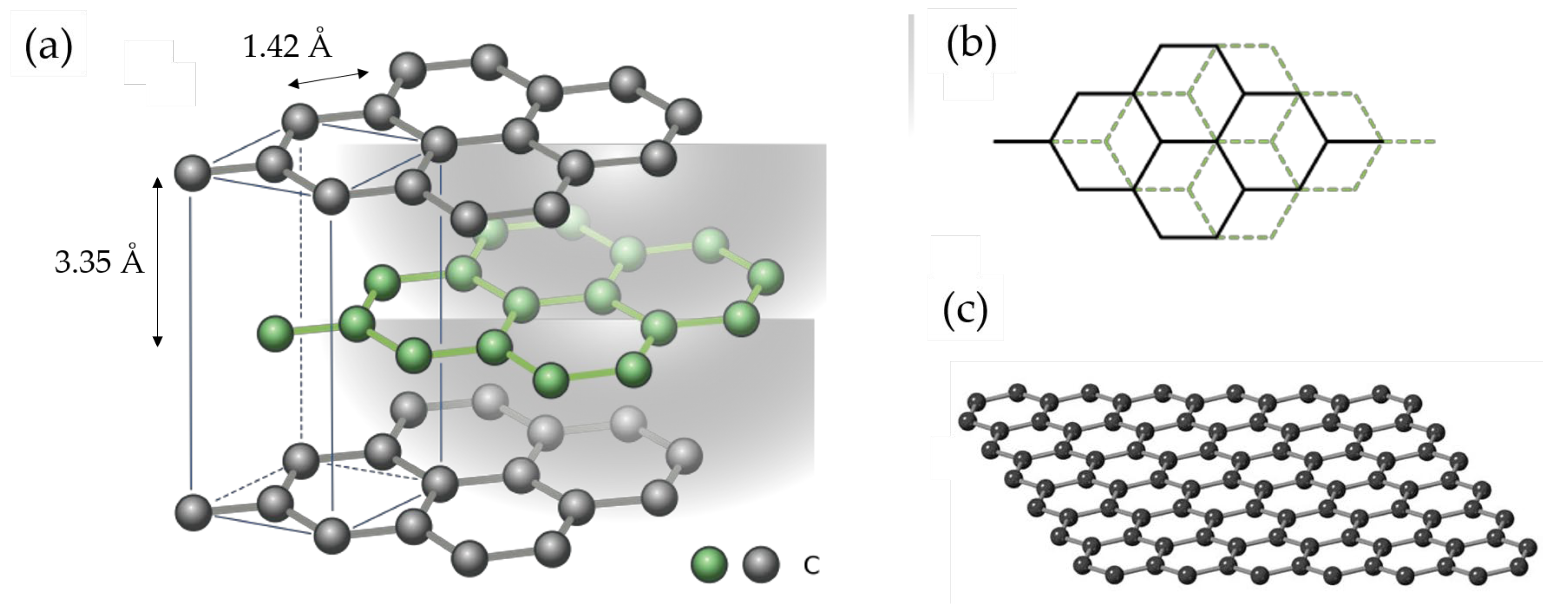
Figure 2.
Schematic illustrations of the structure of (a) graphite, (b) soft (disordered, graphitizable) carbon, and (c) hard (disordered, non-graphitizable) carbon.
Figure 2.
Schematic illustrations of the structure of (a) graphite, (b) soft (disordered, graphitizable) carbon, and (c) hard (disordered, non-graphitizable) carbon.
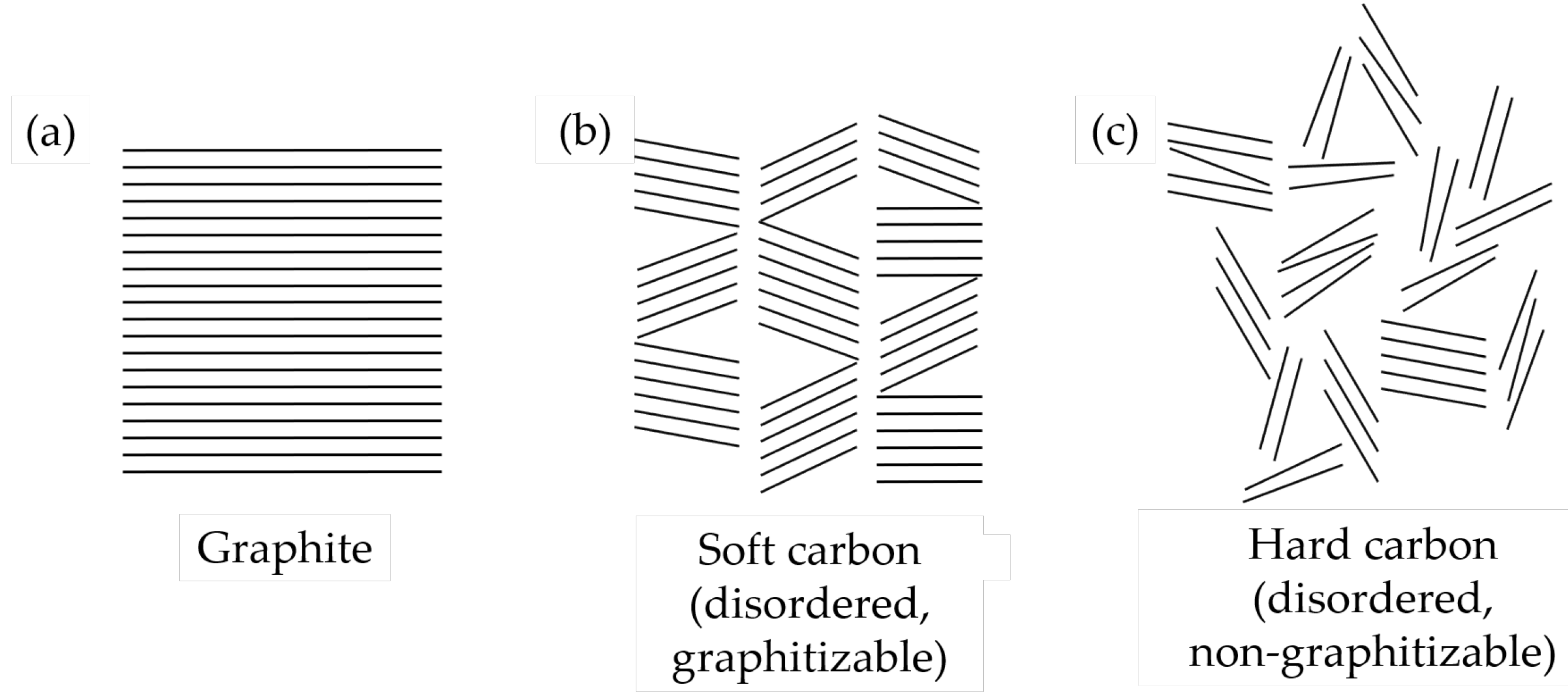
Figure 3.
Typical structure of a (a) CNT (credit image: Mrs. Plugiano, [127]), (b) CNC (adapted from ref. [128]), and (c) CNS materials (adapted from ref. [129]).
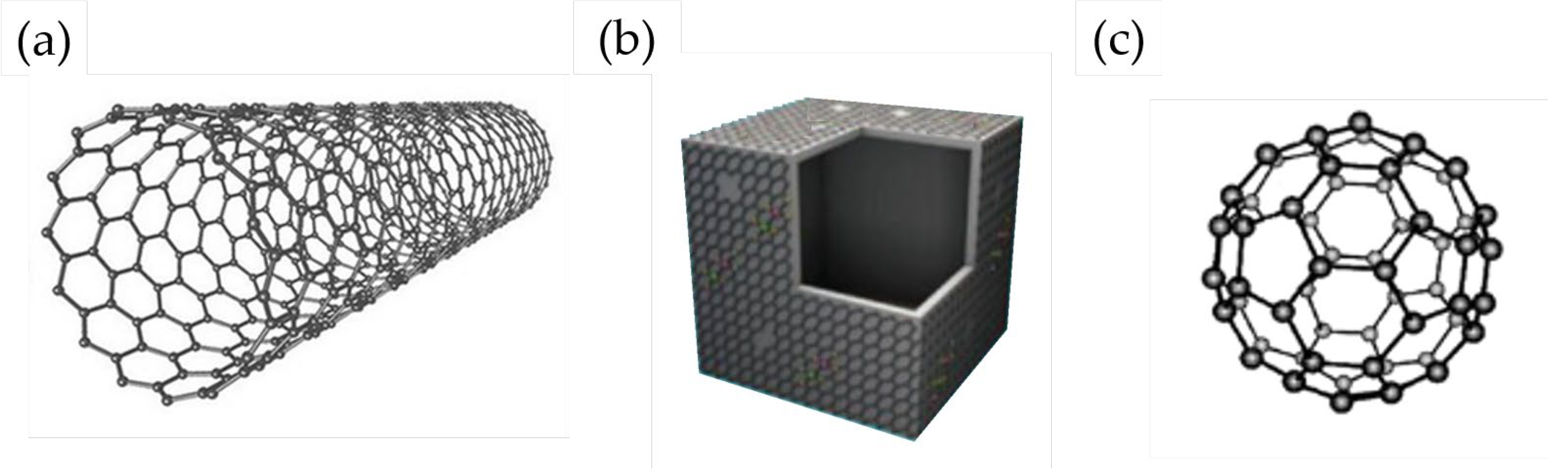
Figure 4.
Comparison of the (a) ICE and (b) capacities of graphite* (values gathered from Table 2) achieved after 50-100 cycles using different graphite properties (red), binder (green) and electrolyte (blue) combinations. *The capacity of graphite: PVDF and graphite: CMC electrodes tested in 1M KFSI in EC: DEC corresponds to a cyclability of only 20 and 8 cycles, respectively.
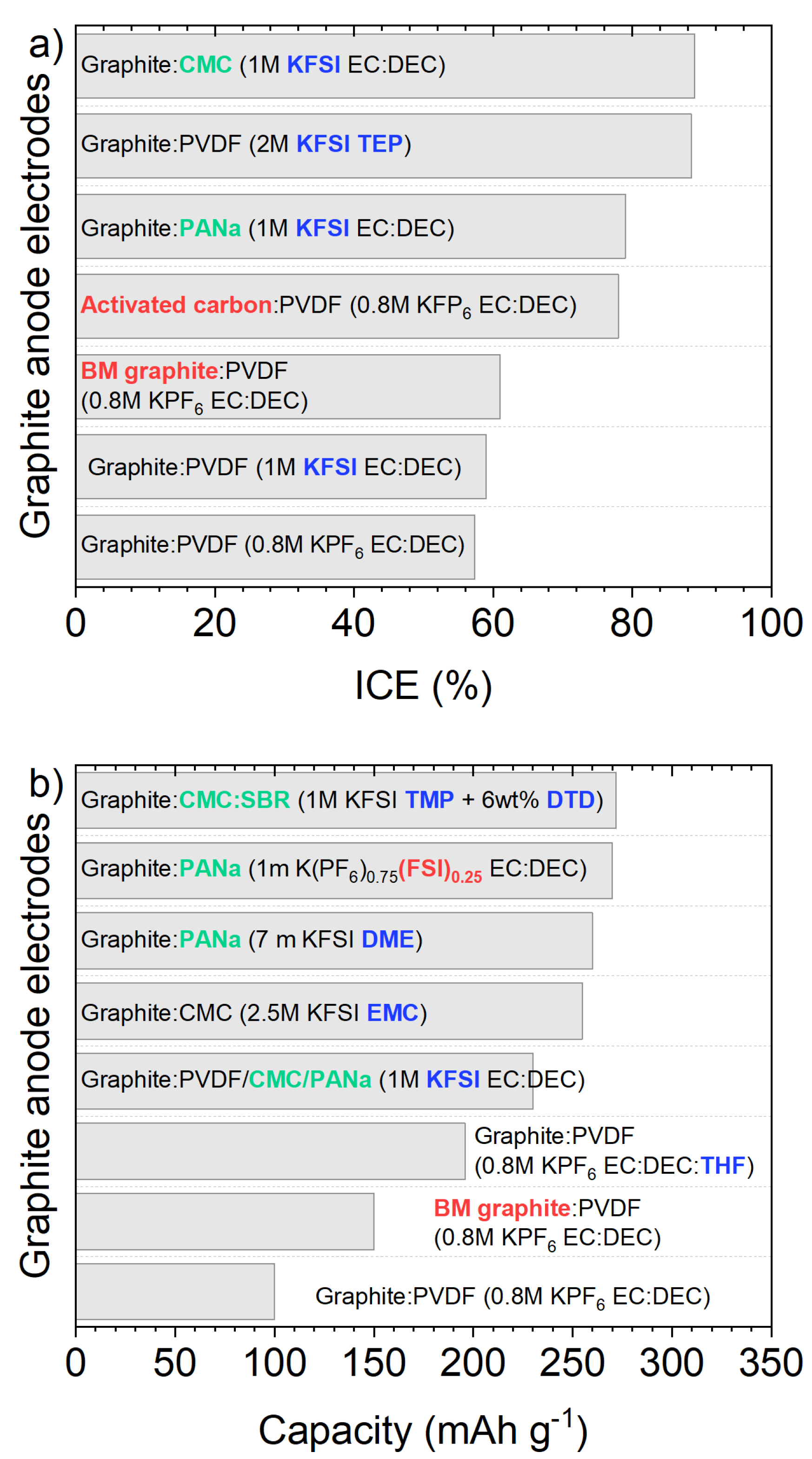
Figure 5.
Comparison of the (a) ICE and (b) capacities of SC or HC achieved after 50-100 cycles using different active material properties (red), binder (green) and electrolyte (blue) combinations.
Figure 5.
Comparison of the (a) ICE and (b) capacities of SC or HC achieved after 50-100 cycles using different active material properties (red), binder (green) and electrolyte (blue) combinations.
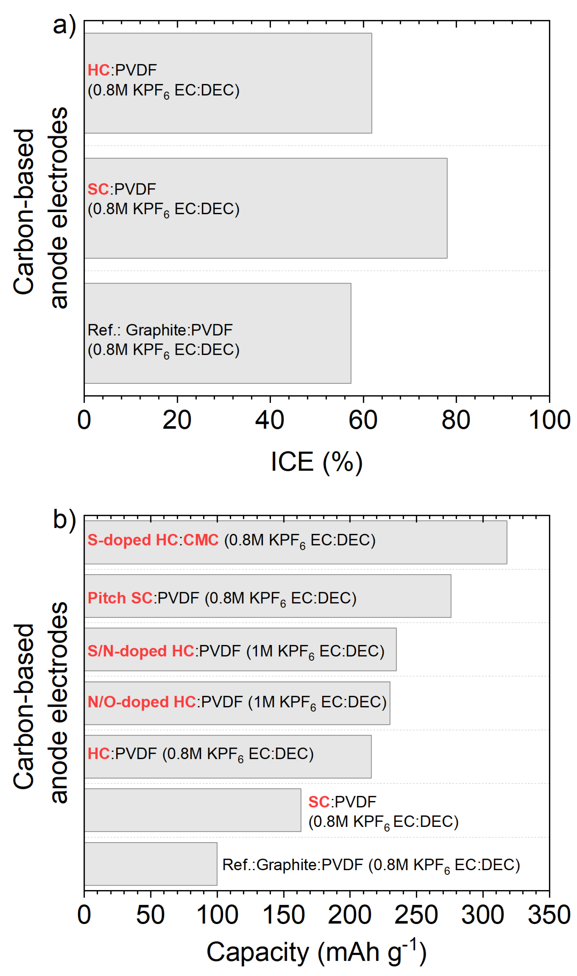
Table 3.
Electrochemical performance of graphene-derived anode materials in KIBs.
| Cyclability | Rate capability | |||||||
| Anode material | Electrolyte | Binder | ICE |
Initial capacity (mAh g-1)@ current density (A g-1) |
Capacity (mAh g-1) |
cycle number@ current density (A g-1) |
Capacity (mAh g-1)@ current density (A g-1) |
Ref. |
| S-s. rGO 1 | 0.5M KPF6/EC: DEC | Free | ~50% | ~222@0.010 | ~107 | 150 cycles@0.010 | 50@0.1 | [53] |
| S.s. rGO aerogel 1 | 0.7M KPF6/EC: DEC | Free | 44% | 267@0.026 | 230 | 100 cycles@0.026 | ~100@0.523 | [99] |
| rGO-2500 | 0.5M KPF6/DEGDME | PVDF | 62% | 125@0.1 | 88.4 | 2500 cycles@0.1 | ~60@1.1 | [100] |
| FLG 2 on Ni foam | 0.8M KPF6/EC: DEC | Free | N/A | ~210@0.1 | ~140-150 | 100 cycles@0.1 | ~62@0.1 | [101] |
| FLG microspheres | 0.8M KPF6/EC: DMC + artif. SEI | CMC | 94% | 285@0.05 | 230 | 1000 cycles@0.2 | 95@1 | [102] |
| F-doped FLG foam | 0.8M KPF6/EC: DEC | PVDF | 41.2% | 356@0.05 | 166 | 200 cycles@0.5 | 213@0.5 | [103] |
| N-doped FLG | 0.8M KPF6/EC: DEC | Free | ~87% | 270@0.05 | 210 | 100 cycles@0.1 | ~50@0.2 | [104] |
| N-doped monolith | 0.8M KPF6/EC: DEC | CMC | ~15% | 487@0.02 | 150 | 1000 cycles@0.5 | ~180@5 | [105] |
| S-s. S-doped rGO | 1M KPF6/EC: PC | Free | 65% | 456@0.05 | 361 | 50 cycles@0.05 | 224@1 | [106] |
| P/O-doped graphene | 1M KClO4/EC: DEC | PVDF | 22.6% | 566@0.05 | ~400 | 600 cycles@0.5 | 222@1 | [107] |
| N/P-doped MLG 3 | 1M KPF6/EC: DEC | PVDF | 15% | 387@0.05 | 242 | 500 cycles@0.5 | 194@1 | [108] |
| N/P-doped G on CC 4 | 1M KPF6/EC: DEC + 5wt%FEC | Free | 53% | 366@0.025 | 281 | 1000 cycles@0.025 | 186@1 | [109] |
| N/O-doped G-l CNC 5 | 1M KPF6/DEGDME | CMC | N/A | ~185@0.5 | 130 | 300 cycles@0.5 | 114@1 | [110] |
| N/S-doped G nrb 6 | 0.8M KPF6/EC: DEC | PAA | 55% | ~267@0.5 | 224 | 500 cycles@0.5 | 212@1 | [111] |
1 S-s. = Self-standing. 2 FLG = Few-layer graphene. 3 MLG = Multi-layer graphene. 4 G = graphene, CC = carbon-cloth. 5 G-l = graphene-like, CNC = carbon nanocages. 6 nrb = nanoribbons.
Table 4.
Electrochemical performance of soft-carbon and hard-carbon anode materials in KIBs.
| Cyclability | Rate capability | |||||||
| Anode material | Electrolyte | Binder | ICE |
Initial capacity (mAh g-1)@ current density (A g-1) |
Capacity (mAh g-1) |
cycle number@ current density (A g-1) |
Capacity (mAh g-1)@ current density (A g-1) |
Ref. |
| SC | 0.8M KPF6/EC: DEC | PVDF | ~78% | ~273@0.007 | ~163 | 50 cycles@0.56 | 140@1.4 | [41] |
| SC hollow microrods | 0.8M KPF6/EC: DMC+5wt.% FEC | PTFE | ~57% | ~340@0.1 | 249 | 100 cycles@0.1 | 214@0.5 | [114] |
| Pitch-derived SC | 0.8M KPF6/EC: DEC | CMC+SBR | ~53% | 296@0.028 200@0.28 |
276183 | 50 cycles@0.028 1000 cycles@0.28 |
115@1.4 | [115] |
| HC microspheres | 0.8M KPF6/EC: DEC | PVDF | 61.8% | 262@0.028 | 216 | 100 cycles@0.028 | 136@1.4 | [117] |
| N-doped CS | 0.8M KPF6/EC: DEC | PVDF | ~88% | 180@0.5 | 180 | 4000 cycles@0.5 | 154@20.2 | [120] |
| P-doped HC | 0.8M KPF6/EC: DEC | PVDF | N/A | 160 | ~155 | 700 cycles@0.3 | ~175@0.5 | [121] |
| S-doped HC | 0.8M KPF6/EC: DEC | CMC | 35.1% | 361@0.05 | 318 | 100 cycles@0.05 | 116@1.6 | [122] |
| N/O-doped HC | 1M KPF6/EC: DEC | PVDF | 25% | 315@0.05 174@1.05 |
230 130 |
100 cycles@0.5 1100 cycles@1.05 |
118@3 | [123] |
| S/O-doped HCM 1 | 0.8M KPF6/EC: DEC | PVDF | N/A | 220@0.2 ~175@1 |
~200 ~110 |
200 cycles@0.2 2000 cycles@1 |
~175@1 | [124] |
| S/N-doped HC | 1M KPF6/EC: DEC | PVDF | ~35% | 294@0.1 174@3 |
235 145 |
300 cycles@0.1 1200 cycles@3 |
174@3 | [125] |
| HC/SC | 0.8M KPF6/EC: DEC | PVDF | N/A | N/A ~166@1 |
185 101 |
100 cycles@0.1 500 cycles@1 |
121@3.2 | [126] |
1 HCM = Hard carbon microspheres.
Table 5.
Electrochemical performance of other carbonaceous anode materials in KIBs.
| Cyclability | Rate capability | |||||||
| Anode material | Electrolyte | Binder | ICE |
Initial capacity (mAh g-1)@ current density (A g-1) |
Capacity (mAh g-1) |
cycle number@ current density (A g-1) |
Capacity (mAh g-1)@ current density (A g-1) |
Ref. |
| S-s. CNF paper 1 (N/O-doped) |
0.8M KPF6/EC: DEC | Free | 24.1% | 272@0.2 223@0.2 |
270 211 |
80 cycles@0.02 1200 cycles@0.2 |
100@7.7 | [131] |
| S-s. N/O-doped CNF 1 | 0.8M KPF6/EC: DEC | Free | 35% | ~280@0.028 ~190@0.28 |
170 | 1900 cycles@0.28 | ~120@1.4 | [132] |
| N-doped (chitin-d) 2 CNF | 0.8M KPF6/EC: DEC | Na-alginate | 37.8% | 215@0.056 | ~200 103 |
100 cycles@0.056 500 cycles@0.56 |
~85 @1.4 | [133] |
| N-doped CNF | 0.8M KPF6/EC: PC | CMC | 49% | 368@0.025 | 248 146 |
100 cycles@0.25 4000 cycles@2 |
101@20 | [134] |
| S-s. Hierarchical CNT 1 | 0.8M KPF6/EC: DEC | Free | 15% | 232@0.1 | 210 | 500 cycles@0.1 | 162@1.6 | [135] |
| Carbon MICROtube (P/S-doped) |
0.8M KPF6/EC: DEC + 3wt.% FEC | PVDF | 42.5% | 450@0.5 N/A |
395 176 |
100 cycles@0.5 2000 cycles@2 |
177@1 | [136] |
| N-doped CNTs | 0.8M KPF6/EC: DEC | PDVD | 23.3% | 380@0.5 | 204 | 1000 cycles@0.5 | N/A | [137] |
| S-s. N-doped CNTs 1 | N/A | Free | 14% | 324@0.02 | 236 | 100 cycles@0.02 | 75@1 | [138] |
| CNTs/GCF | 0.7M KPF6/EC: DEC | Free | 24% | 229@0.1 132@0.5 |
226 127 |
800 cycles@0.1 2000 cycles@0.5 |
~75@1 | [139] |
| Graphitic CNCs | 1M KFSI/EC: PC | CMC+PAA | 40% | 212@0.056 | 195 | 100 cycles@0.056 | 175@9.8 | [141] |
| S-grafted CNSs | 0.8M KPF6/EC: DEC | PVDF | 51.4% | 572@0.25 160@3 |
~290 ~150 |
250 cycles@0.2 1000 cycles@3 |
110@5 | [142] |
| Amorphous OMC | 0.8M KPF6/EC: DEC | PVDF | 63.6% | 307.4@0.05 ~175@1 |
257 147 |
100 cycles@0.05 1000 cycles@1 |
114@0.4 | [143] |
| S-s. Hollow carbon 1 (neuron-like) |
0.8M KPF6/EC: DEC | Free | 72.1% | 340@0.028 | 250 ~115 |
150@0.14 ~175@0.28 |
~115@0.56 | [144] |
| 2D Sheet-like carbon (N, P-doped) |
0.8M KPF6/EC: DEC | PVDF | 49% | 404@0.1 250@1 |
350 179 |
300 cycles@0.1 2000 cycles@1 |
90@5 | [145] |
| 3D carbon | 0.8M KPF6/EC: DEC | CMC | 23.6% | 430@0.05 ~185@1 |
270 162 |
100@0.05 2000@1 |
78@5 | [146] |
1 S-s. = self-standing. 2 chitin-d = chitin-derived.
Table 6.
Electrochemical performance of titanium oxides as anode materials in KIBs.
| Cyclability | Rate capability | |||||||
| Anode material | Electrolyte | Binder | ICE |
Initial capacity (mAh g-1)@ current density (A g-1) |
Capacity (mAh g-1) |
cycle number@ current density (A g-1) |
Capacity (mAh g-1)@ current density (A g-1) |
Ref. |
| HeTiO2eC microtubes | 0.8M KPF6/EC: DEC | CMC | 49.1% | 241@0.1 163@0.5 |
197 133 |
200 cycles@0.1 1200 cycles@0.5 |
97@2 | [148] |
| TiO2-coated polyaniline | 3M KFSI/DME | CMC | 56.6% | 219@0.05 110@0.5 |
198 150 |
400 cycles@0.05 2500 cycles@0.5 |
80@5 | [149] |
| G-TiO2 | 0.8M KPF6/EC: DMC | Na-alginate | 39% | 320@0.05 129@5 |
222 96 |
400 cycles@0.1 3000 cycles@5 |
129@5 | [150] |
| TiO2@NGC | 1M KPF6/EC: DMC | PVDF | 44% | 228@0.05 ~120@0.5 |
~270 185 |
100 cycles@0.05 2000 cycles@0.5 |
114@1 | [151] |
| C-coated flower-like TiO2 | 3M KFSI/DME | Na-alginate | 32% | 172@0.036 ~100@0.36 |
137 ~100 |
100 cycles@0.036 2500 cycles@0.36 |
93@0.7 | [152] |
| TiO2/graphene composite | 0.8M KPF6/EC: DMC | PVDF | 42% | 337@0.1 | 245 | 100 cycles@0.1 | 174@0.6 | [153] |
| Ta-doped TiO2/CNFs | 1M KFSI/EC: DMC | PVDF | 37.9% | 255@0.05 122@2 |
N/A 149 |
N/A 800 cycles@2 |
103@5 | [154] |
| K2Ti4O9 | 1M KPF6/EC: PC | PVDF | ~20% | ~80@0.1 | ~40 | 30 cycles@0.1 | 50@1 | [156] |
| M-KTO (KTO = K2Ti4O9) | 1M KPF6/DEGDME | PVDF | 25.9% | 151@0.05 120@0.2 |
~92 50 |
100 cycles@0.05 900 cycles@0.2 |
81@0.3 | [157] |
| K2Ti8O17 nanorods | 0.8M KPF6/EC: DMC | PVDF | ~66% | 182@0.02 | 102 | 50 cycles@0.02 | 44@0.5 | [158] |
| KTi2(PO4)3 nanocubes | 0.8M KPF6/EC: DEC | PVDF | ~92% | ~68@0.064 | ~30 | 100 cycles@0.064 | N/A | [159] |
| KTi2(PO4)3 nanocubes@C | 0.8M KPF6/EC: DEC | PVDF | ~78% | ~60@0.064 | ~80 | 100 cycles@0.064 | N/A | [159] |
| KTiOPO4 | 5M KFSI/DEGME | CMC | 66% | 102@0.005 | ~82 | 50 cycles@0.005 | N/A | [160] |
| KTiOPO4 NPs | 0.8M KPF6/EC: DEC | CMC | N/A | 161@0.15 84@3 |
139 66 |
100 cycles@0.15 10000 cycles@3 |
84@3 | [162] |
| KTiPO4F@C + G nanoplates | 1M KPF6/EC: PC | PVDF | ~60% | ~205@0.026 N/A@0.13 |
133 130 |
100 cycles@0.026 1000 cycles@0.13 |
50@1 | [161] |
| K2Ti6O13@C | 1M KFSI/E: DEC | PVDF | ~25% | 151@0.025 | 119 | 200 cycles@0.025 | 65@0.5 | [163] |
Table 7.
Electrochemical performance of vanadium oxides (and derivatives) as anode materials in KIBs.
Table 7.
Electrochemical performance of vanadium oxides (and derivatives) as anode materials in KIBs.
| Cyclability | Rate capability | |||||||
| Anode material | Electrolyte | Binder | ICE |
Initial capacity (mAh g-1)@ current density (A g-1) |
Capacity (mAh g-1) |
cycle number@ current density (A g-1) |
Capacity (mAh g-1)@ current density (A g-1) |
Ref. |
| K0.23V2O5 | 0.8M KPF6/EC: DEC | PVDF | 49.3% | 404@0.02 ~265@0.1 |
122 97 |
150 cycles@0.02 100 cycles0.1 |
92@0.4 | [165] |
| K2V3O8 | 0.8M KPF6/EC: DMC | CMC | ~60% | 282@0.05 | 84 | 180 cycles@0.1 | 103@0.5 | [166] |
| SA-VO2 | 0.8M KFSI/E: DEC | PVDF | 64.4% | 290@0.05 205@0.5 |
288 177 |
50 cycles@0.05 500 cycles@0.5 |
141@2 | [167] |
| VO2-V2O5/NC | 0.8M KPF6/EC: DMC: DEC | PVDF | N/A | N/A@0.1 ~540@1 |
501 256 |
120 cycles@0.1 1600 cycles@1 |
108@10 | [168] |
| S-s. V2O3 NPs@PNCNFs 1 | 0.8M KPF6/EC: DEC | Free | 60% | 215@0.05 | 206 | 500 cycles@0.05 | 134@1 | [169] |
| V2O3 NPs@C nanosheets | 1M KFSI/DME | PVDF | 31% | ~254@0.1 N/A@2 |
267 148 |
100 cycles@0.1 1800 cycles@2 |
116@5 | [170] |
1 S-s. = self-standing.
Disclaimer/Publisher’s Note: The statements, opinions and data contained in all publications are solely those of the individual author(s) and contributor(s) and not of MDPI and/or the editor(s). MDPI and/or the editor(s) disclaim responsibility for any injury to people or property resulting from any ideas, methods, instructions or products referred to in the content. |
© 2024 by the authors. Licensee MDPI, Basel, Switzerland. This article is an open access article distributed under the terms and conditions of the Creative Commons Attribution (CC BY) license (http://creativecommons.org/licenses/by/4.0/).
Copyright: This open access article is published under a Creative Commons CC BY 4.0 license, which permit the free download, distribution, and reuse, provided that the author and preprint are cited in any reuse.


