1. Introduction
Inspection within the industry plays a very important role in the manufacturing process. Machine vision systems automate complex tasks for positioning inspection, identification, verification, measurement, and fault detection within the production chain. Unlike human inspectors, who can process only a certain amount of information at a time, machine vision systems work tirelessly, performing 100% automated inspection [
32], improving quality and aggregating yields. Higher industries and lower costs in the production chain [
10]. High quality and consistent product appearance and functionality [
19] drive a positive customer experience and ultimately increase product market share.
Industries have been using Automatic Optical Inspection (AOI) to assist in inspecting defective PCB components [
25]. AOI systems generally use defect inspection methods by scanning the board and performing analysis, using methods such as matching local features as a standard image [
15], and morphological image comparison to detect defects obtaining excellent results; however, problems with reflective materials can cause false disapprovals. With the increasing miniaturization of components inserted on the surface of PCBs, the challenges to ensure the detection of numerous components inserted in PCBs are becoming increasingly complex [
5], for the detection and recognition of various components, such as screws, threads, gasket, and thermal paste, whose recognition is difficult through manual visual inspection [
24], increasingly requiring the automation of inspection processes through vision systems for defect detection [
14].
In this article, we propose the development of an industrial hydro system using machine vision and vision sensor to inspect to detect the absence of screws, screw threads, excess or absence of thermal paste, conductive pad, and chassis tab on the surface of the main PCBs of the car radio, produced in an automotive industry.
2. Theoretical Frame
Machine vision is strongly related to computer vision, which enables significant gains in efficiency and quality reliability for failure mode detection. This requires good lighting systems, sensors, cameras, and computer systems such as a vision builder for image processing [
31].
With the advancement of artificial intelligence and the constant improvement of cameras and sensors, machine vision has been gaining ground within industries for measurement and decision-making to determine compliance [
21]. According to [
1], machine vision has been used in processes with a large scale of repetition, benefiting several industrial activities.
2.1. Process Failure Mode and Effect Analysis - FMEA
The manual quality inspection process needs to have a minimum of failures during production. Through the inspection guarantee, it is possible to reduce defects. With this need, the automotive industry adopted the FMEA Failure Mode and Effect Analysis AIAG-VDA quality tool to evaluate possible process defects to prevent the occurrence.
The FMEA manual consists of an analysis technique developed to be applied in components, the objective of which is to know all the possible defects and evaluate the effects these failures have on the other components, according to the FMEA manual.
The main objective of the FMEA is to identify defects, evaluate the causes and effects, and propose solutions to prevent their occurrence, with the final objective of producing a product free of defects in the production process and during customer use, according to the FMEA manual [
6].
Each component is examined to identify possible defects. For each defect mode, three values are assigned: the Severity of the defect impact (“S”), the Occurrence of the defect mode (“O”), and the Detection is the ability to detect the defect before it occurs (“D”). The multiplication of these three variables generates the risk value, NPR, according to the FMEA manual, shown in
Figure 1.
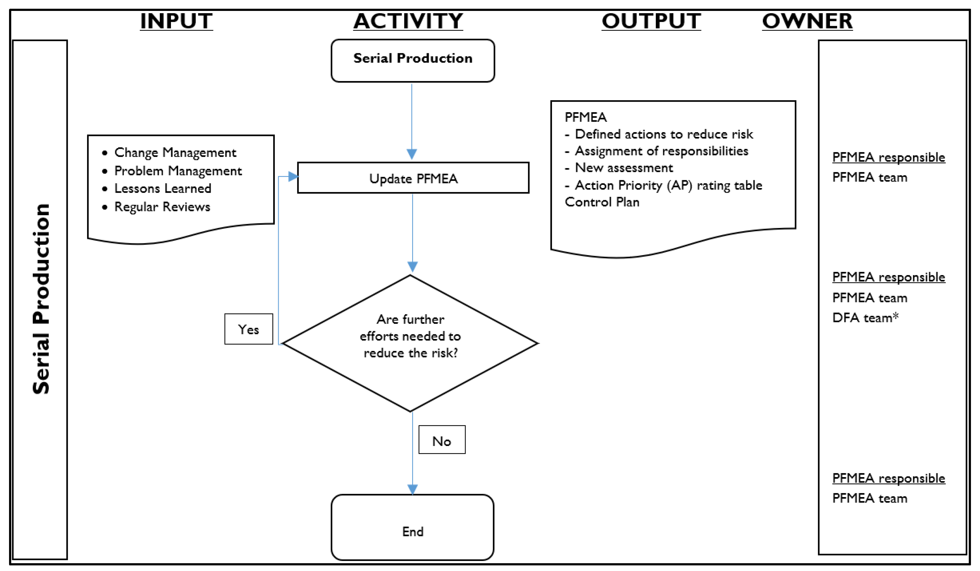
During serial production, FMEA needs regular reviews based on lessons learned, problems, and change management using the process flow shown in
Figure 2.
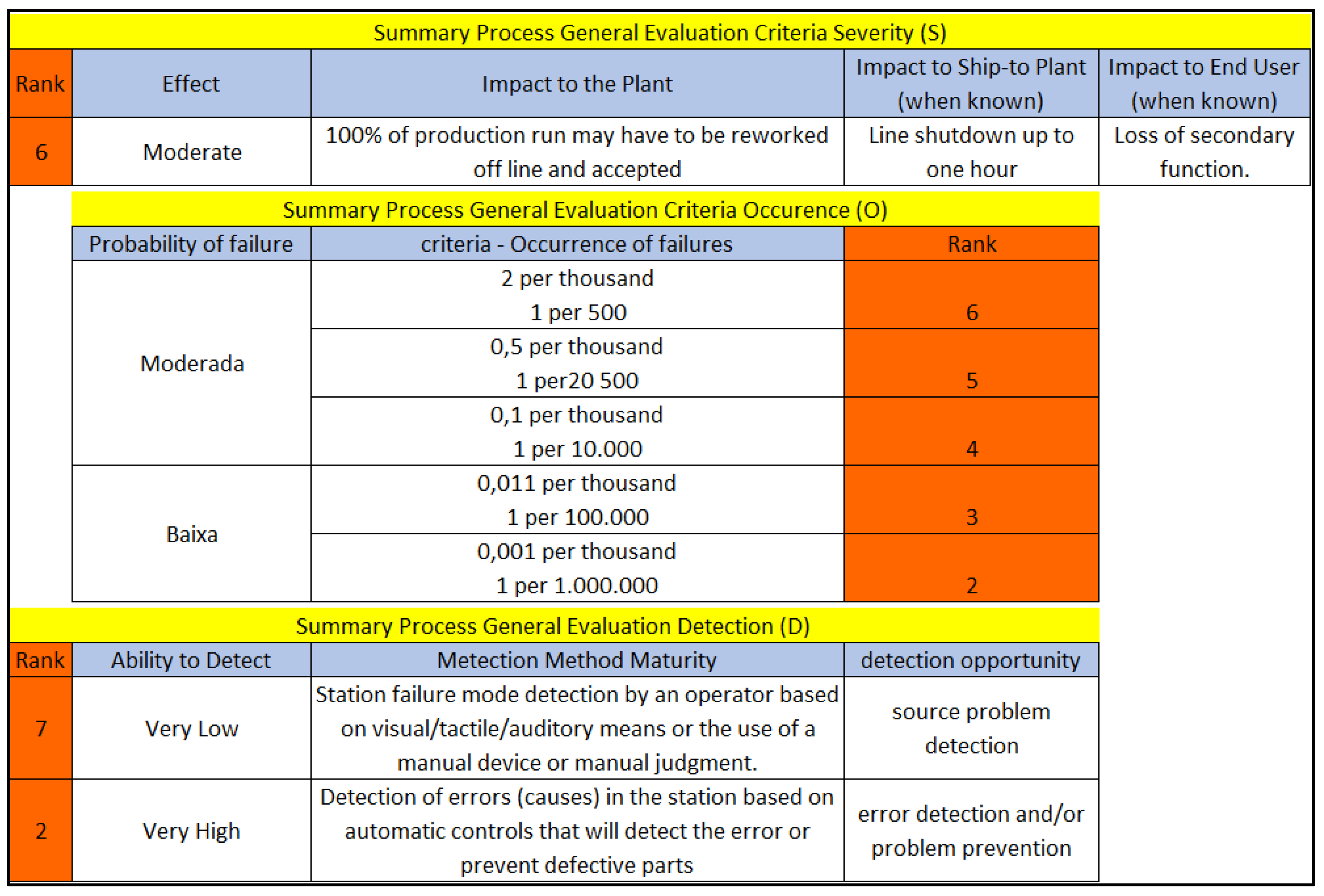
The FMEA reference manual indicates that when the severity is 6, the risk must be treated by recommended actions, as shown in
Figure 3, or existing project controls, according to the FMEA manual. Every action must reduce the severity, occurrence, or non-detection and have the person responsible and a deadline to be fulfilled.
Based on the Detection probability table, the grade 7 attributed to detection in the process FMEA is high grade and indicates that the probability of the operator detecting a possible failure is very low [
12,
25].
According to [
5,
8], the manual quality inspection process must be reliable to meet consumer expectations and the standards the automotive industry sets. However, it is common for this inspection to take place manually, which can be time-consuming, tedious, generate high operating costs, be subject to human error, and present difficulties in standardizing the results, making its automation desirable.
According to [
7,
22], in the case of Industry, the existing base of computerized automation and a business vision focused on digital transformation gives rise to the concept of Industry 4.0. Based on the integration of information and communication technologies that allow reaching new levels of productivity, flexibility, quality, and management, enabling the generation of new strategies and business models for the industry through communication, integration, and connection through sophisticated software and sensors, to spread advanced manufacturing technologies.
The purpose of this research is to develop a new methodology for using machine vision to carry out automatic inspection and increase quality reliability. According to the FMEA manual, the action taken through automatic controls will cause the change from rank 7 (low detection capacity) to rank 2 (high detection capacity), shown in
Figure 3, generating a significant increase in failure detection.
2.2. Inspection Process
Inspection processes increasingly use the concept of flexible manufacturing in the automotive industry, where it is possible to produce several models using the same manufacturing plant [
3]. A large part of the line setup is prepared by human operators, which in many cases increases compliance errors, such as the incorrect replacement or feeding of components.
According to [
8], sensing technologies are proposed to provide reliability in the manufacturing process without excessive human dependence.
Several manufacturing service providers have been offering industries various applications for production and inspection using machine vision aimed at industrial demand, such as applications for component assembly, which uses vision systems to position objects at a given coordinate for insertion or inspection of components on the surface of the PCB. In the automatic visual inspection, the inspection submits the components to the result of a specific condition of compliance or rejection, according to the pre-established parameters in the strategy for each inspected item.
2.3. Failures Modes Defined
Several failures can be detected in a production process, which may have their origin in the different phases of the project, such as in the line setup, jigs, or even non-compliance with the production instructions [
13].
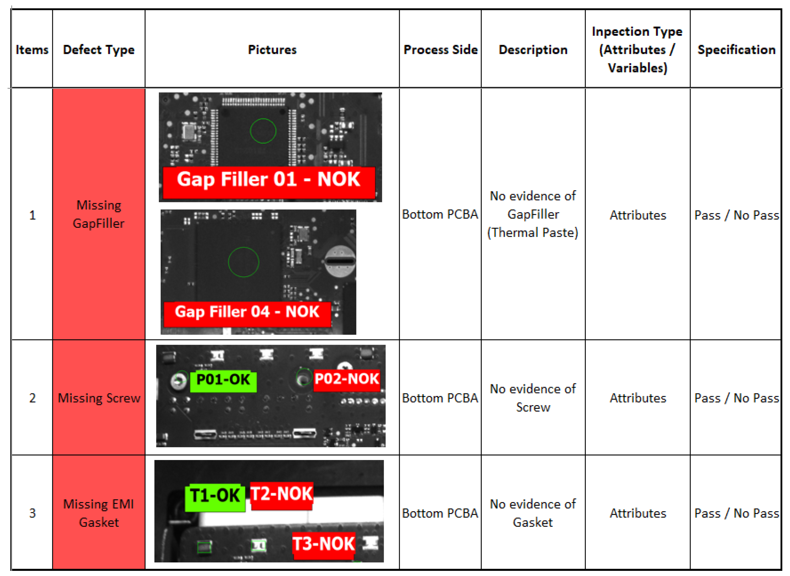
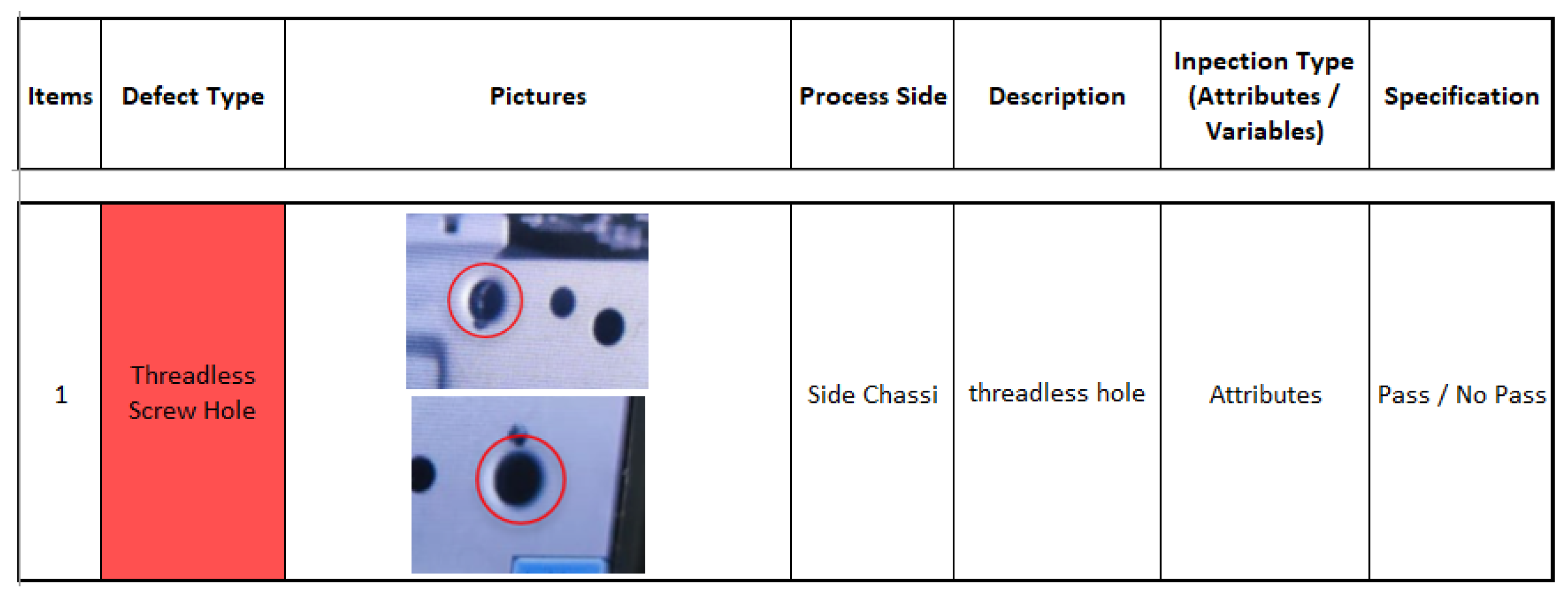
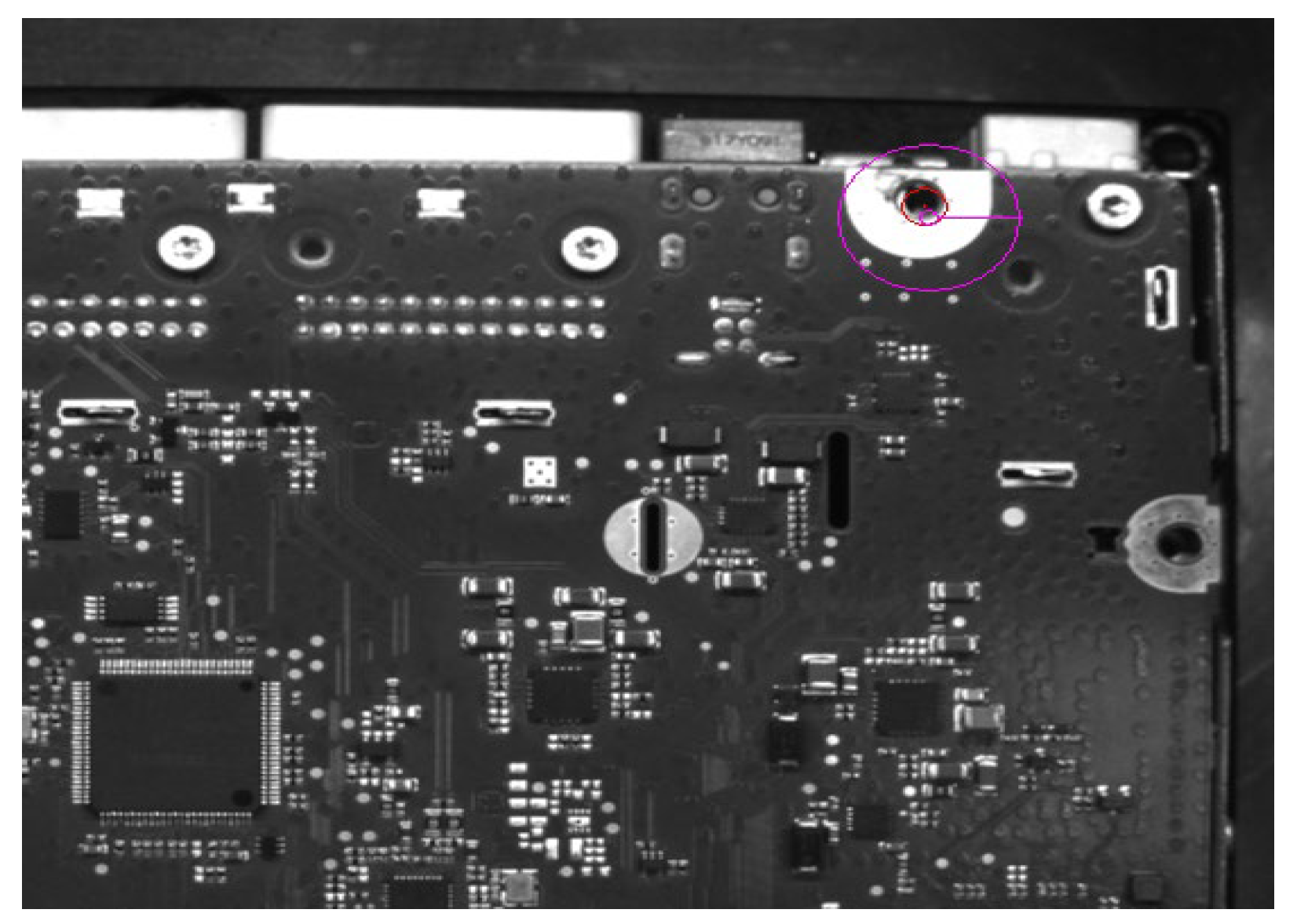
Figure 4 and
Figure 5 show some flaws in the production of the main PCB and the chassis that make up the car radio.
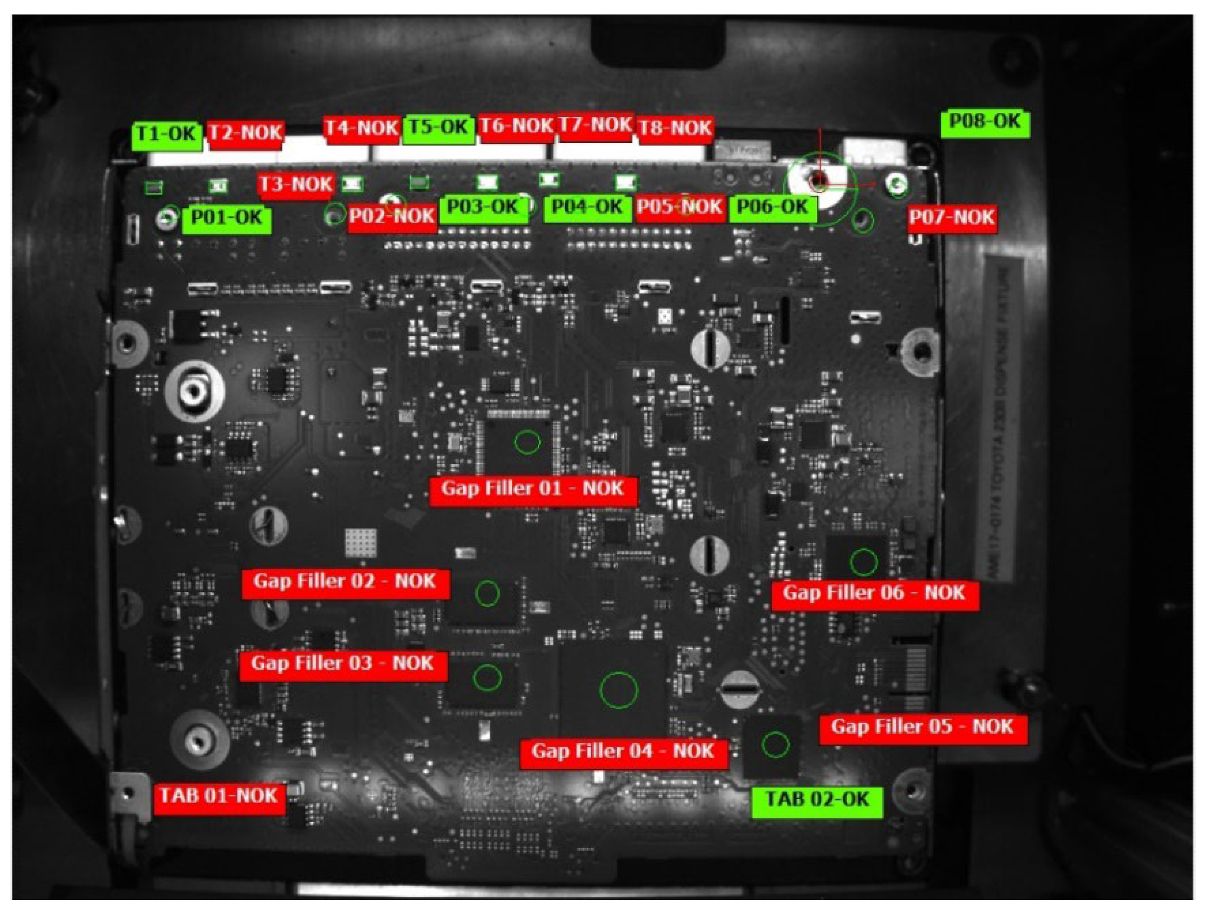
Figure 4 shows the failure modes inspected at the workstation, such as missing thermal paste (gap filler), missing screw, and missing conductive pad, performed on the PCB surface.
Figure 5 shows the failure mode without thread for the screw hole on the car radio chassis inspected at the workstation.
2.4. Manausl Inspection and Machine Vision
Visual inspection processes can occur in two ways, by human or automatic analysis and judgment [
5]. The efficiency of manual inspection is often compromised by environmental and human factors, which fail or reject the human capacity for evaluation and perception, which are compromised throughout the workday by fatigue [
4].
According to [
18], using intelligent processes used in the industry using machine vision has been one of the main technologies used to carry out inspections, increasingly showing its efficiency and quickly promoting the replacement of human visual inspection. Machine vision is a system that automatically collects and processes images of a real object by capturing optical devices and sensors autonomously.
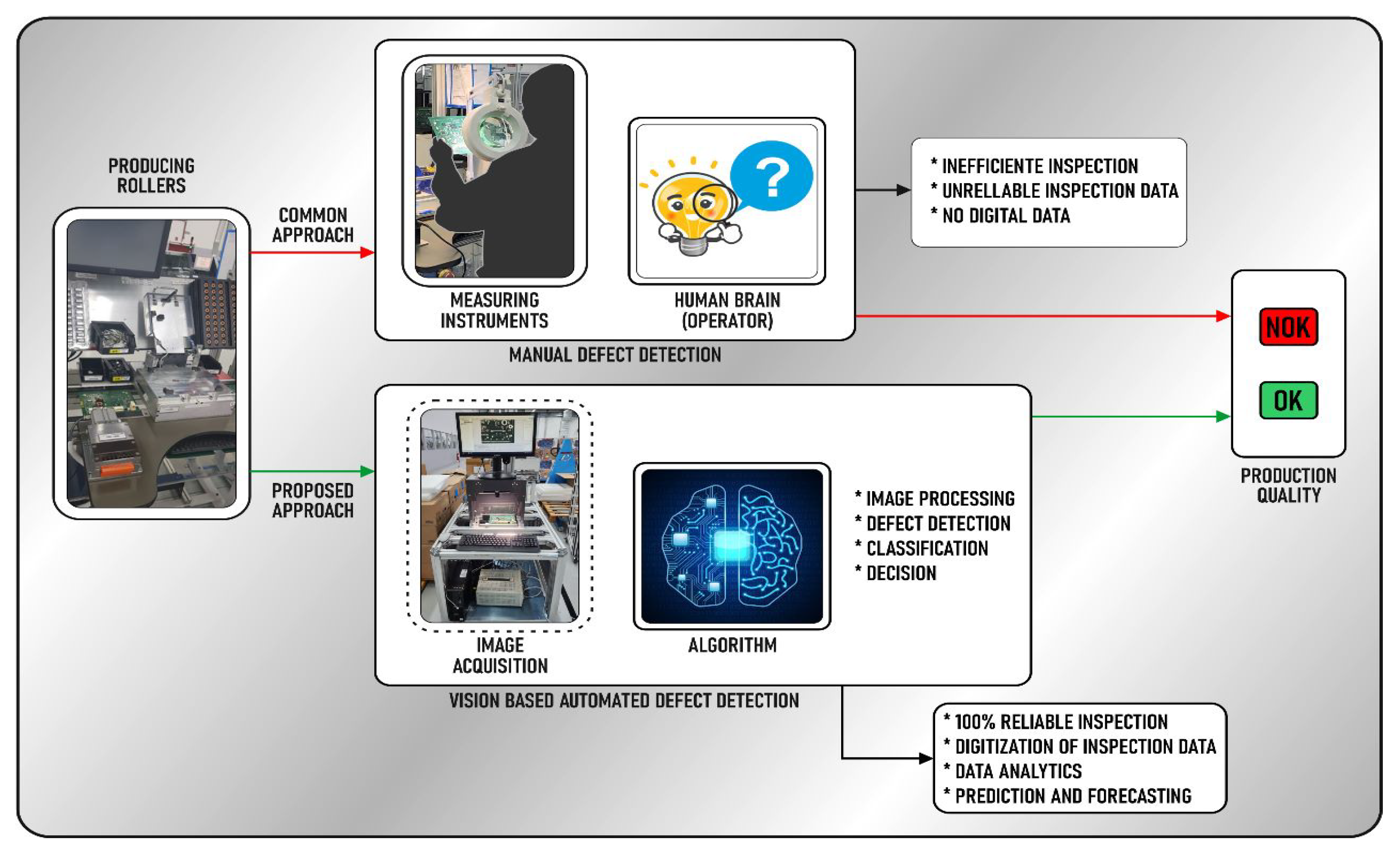
Figure 5 demonstrates the use of manual process inspection and the automatic use made through machine vision.
Figure 6 shows the image capture process for carrying out the inspection. In contrast, the manual process is done by an operator who performs the judgment process, which often, added to fatigue, can affect the judgment to approve or disapprove the item. inspected. On the other hand, inspection using machine vision does not undergo biological variations over time, which does not affect any stage of the inspection to which they were submitted [
27].
3. Machine Vision System
Machine vision is best viewed as a technique that can be used to achieve various tasks. Industrial inspections, observation, monitoring, and sorting are some machine vision, although machine vision is not limited to only accomplishing these examples [
18,
20,
28]:
Industrial Inspection: Machine vision is commonly associated with this use case. It uses machine vision to locate defects in a product.
Process Monitoring: Machine vision cameras come in different types, are made to be reliable in different environments, and have a long lifespan. Because of this, machine vision cameras help observe or monitor certain situations.
Sorting: Machine vision can be used in various ways to sort different objects based on color, shape, size, and others. The software component of machine vision identifies the object, and that data can be later passed on to another device to sort the object physically.
Optical measurements: Machine vision can also serve as a method to perform measurements visually. Suppose the setup is stable and the incoming images are acquired under consistent conditions. In that case, information can be extracted from the image and converted into real-world units as a result.
Robotics: Like the method of attaining optical measurements, controlling robotic movement is another common use for machine vision. Using the incoming images as a reference, data can be calculated and translated as commands to the robotic components to move or change settings.
Machine Vision is the process of: Acquisition – acquiring images; Image processing – digital manipulation of images; Data extraction – extracting quantitative data from images and making autonomous decisions – based on the extracted data [
27].
The machine vision systems aim to inspect 24 items on the surface of the PCB and 7 holes for screwing in the car radio chassis automatically from the capture of images of the PCB and the chassis inserted in the inspection station. The main processes and items to be inspected will be:
1) Find the fiducial points in the image.
2) Binarization of the image.
3) Component mapping based on the information provided by the golden sample image.
4) Gap filler detection in components.
5) Screws and pad detection.
6) Detect thread to screw.
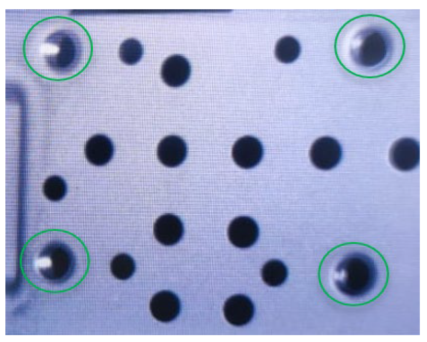
The location of the PCB fiducial is the initial and critical process since the displacement correction reflects on the result of every inspection. The fiduciary points are generally symmetrical, represented in a circular shape [
30], as shown in
Figure 7. To locate the fiducial point of the plate, the Hough transform was inserted in the algorithm strategy, which proposes the method used in image processing to detect parameterizable shapes with lines, ellipses, and circles [
29].
After defining the fiducial of the PCB, the real object is captured. An image can be defined mathematically, as a two-dimensional function f(x,y), with x, y ∈ ℜ², where x and y are the spatial coordinates that identify a given point, f(x,y) denotes the gray level intensity of the image at a given point in the image, where ℜ the set of real numbers [
20].
A digital image is a function f(x,y) discretized both in spatial coordinates and in the intensity of gray levels and can be represented through a matrix in which the row and column indices identify an image element (pixel) and the element value identifies the gray level applied to the image [
17].
After capturing the image, the captured image is binarized, which consists of converting the various levels of gray [0, 255] to [0, 1] that defines pixels with a value of 1 representing white and those with a value of 0 representing black, or vice versa [
16], shown in Equation 1.
where b is the binary output image, f is the input image in gray levels, and Lb is the threshold chosen for pixel grouping.
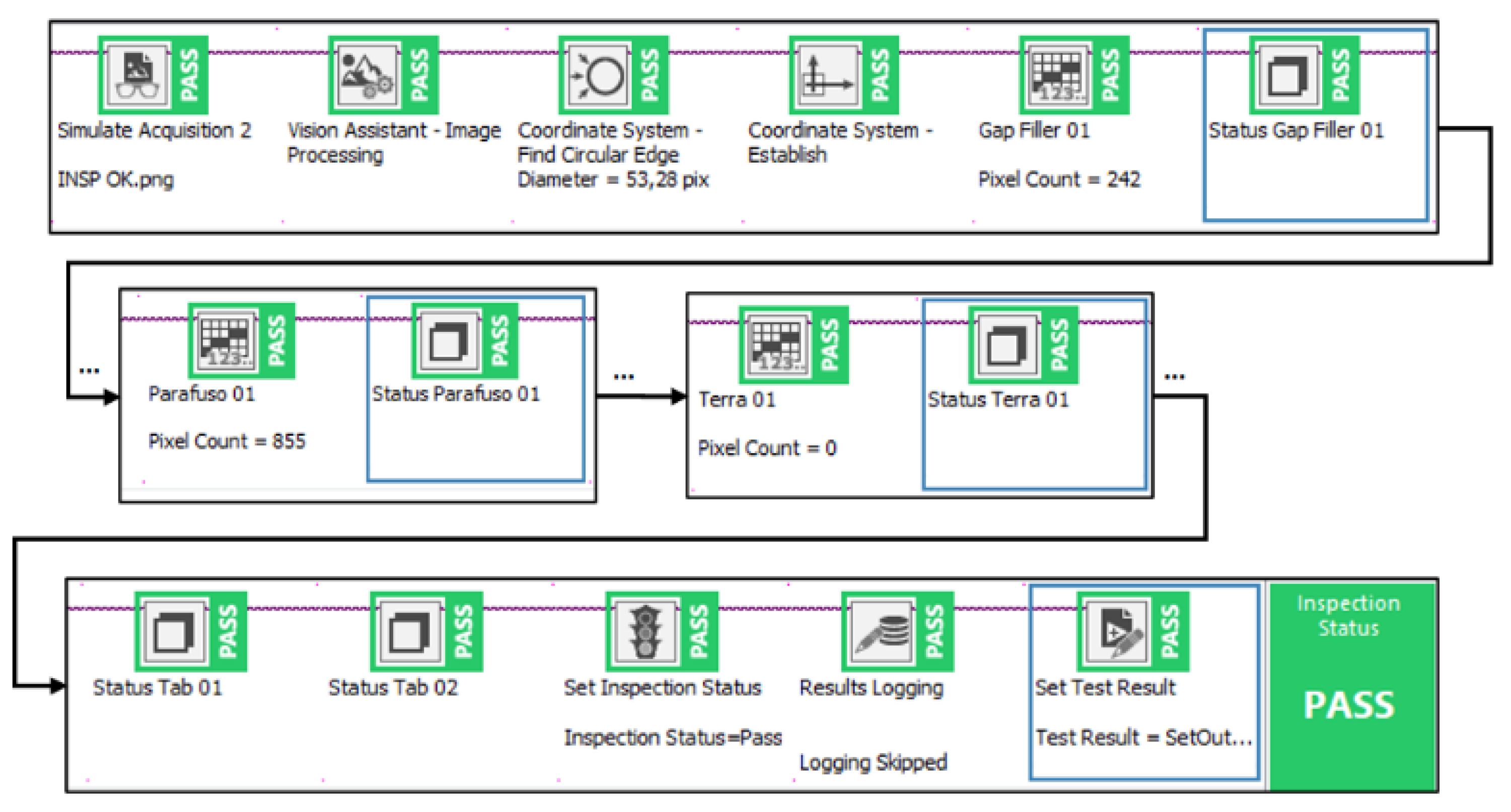
As shown in
Figure 8, the component mapping was developed by creating the strategy using the Vision Builder tool.
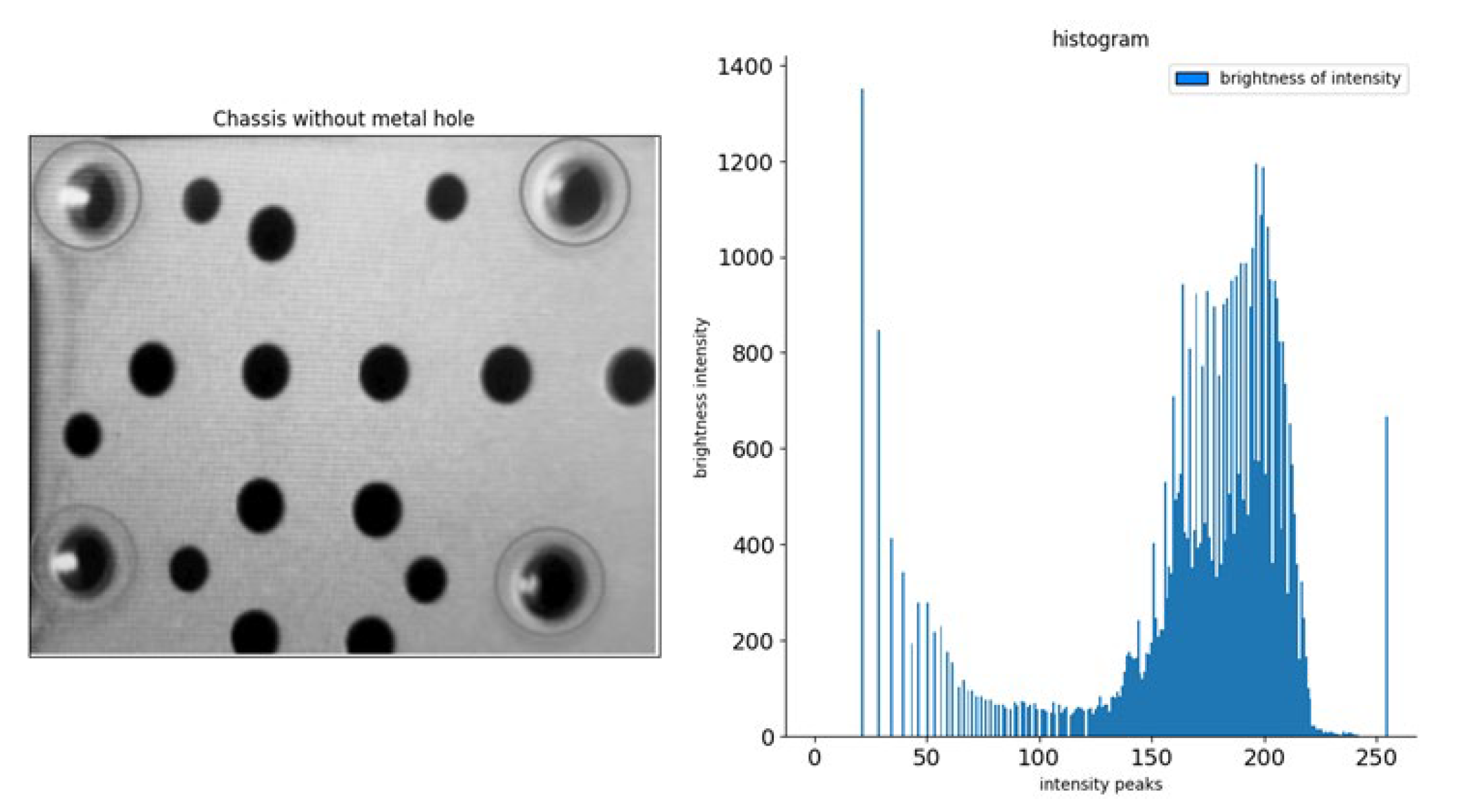
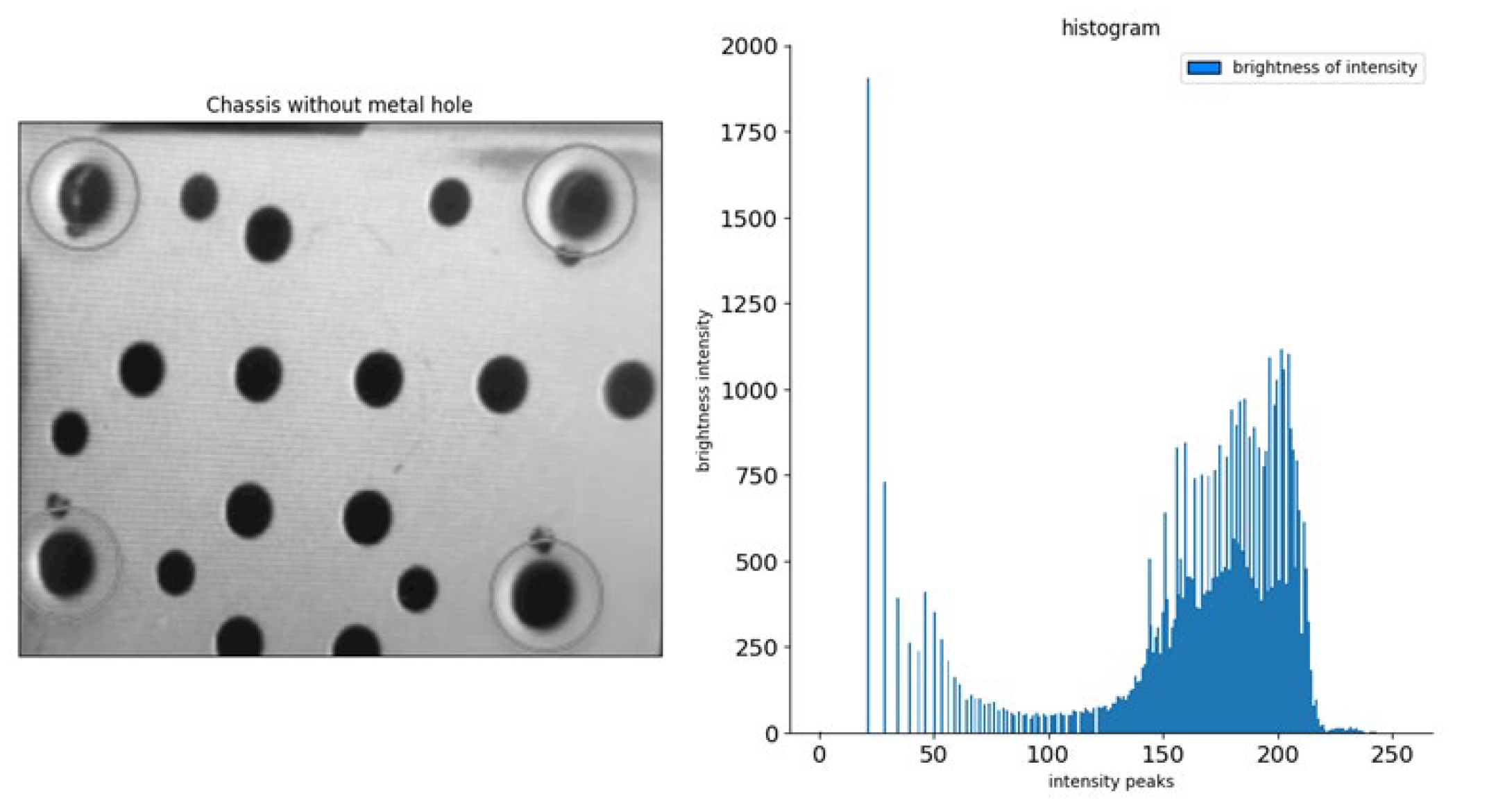
For the thread's inspection on the chassis, the luminosity criterion was defined to detect the metalized hole on the car radio chassis. An image sensor was used to detect the brightness intensity in the chassis hole. Using the properties of histograms, since they do not preserve the spatial information of pixel distributions, considering only the number of pixels with a specific gray level [
2], an effect is shown in
Figure 9.
Even with different images, the histograms can be identical, allowing their use for pattern recognition purposes [
11], as illustrated in
Figure 10 and
Figure 11.
4. Results and Discussions
During the execution of the tests to evaluate the strategy, Equation 1 describes the perfect adaptability of the algorithm in treating data entry.
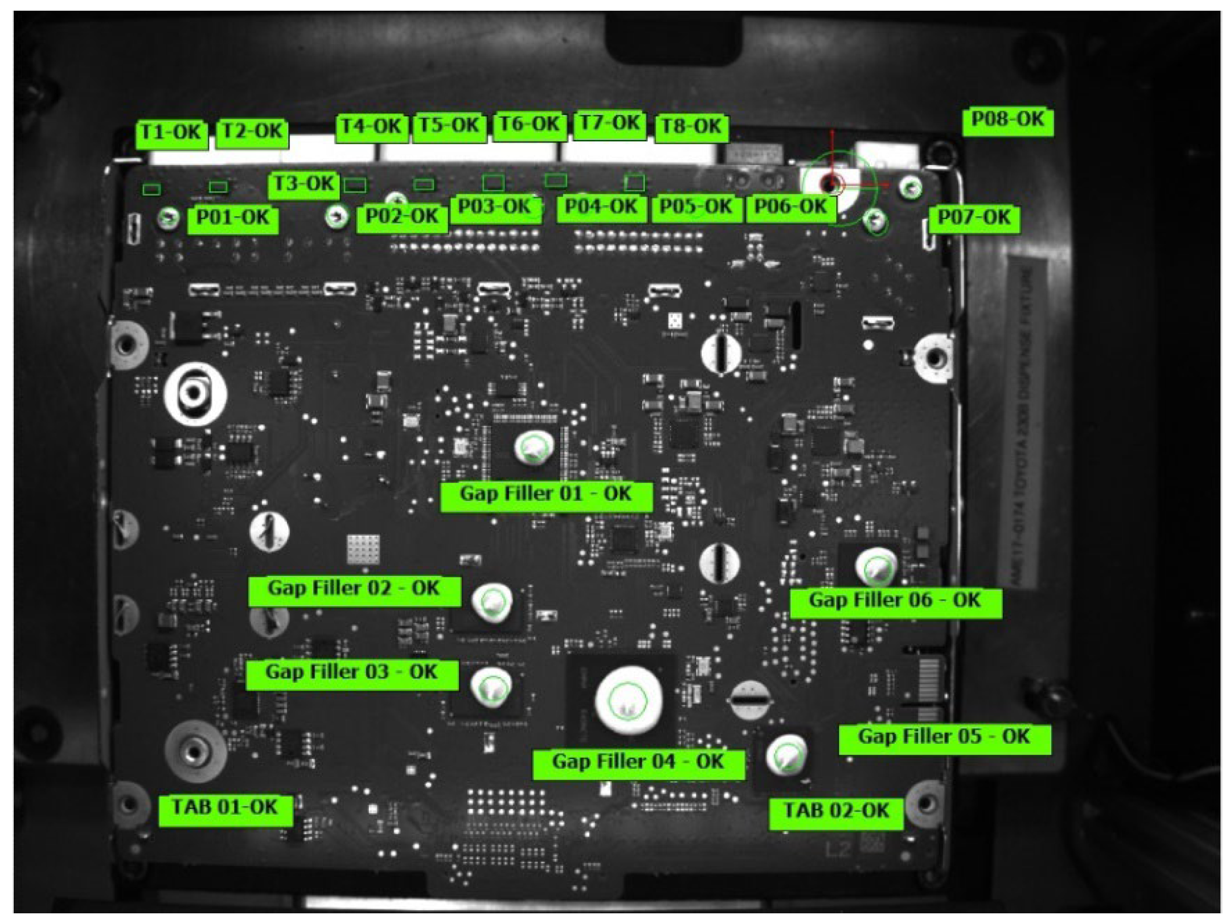
The failure detection described in the defined failure modes had excellent results, as illustrated in
Figure 10.
Figure 11 illustrates the system's efficiency in identifying PCBs and chassis within the established conformities.
In
Figure 12, the chassis image has pixels between 25 and 245. It is noticed that there was much dispersion in the number of pixels with the highest intensity of brightness, reaching 1400 brightness intensity, with the most intense pixels at 30, 35, 200, and 220, precisely at the points where there was a higher incidence of brightness.
In
Figure 13, the chassis image has pixels between 25 and 230. It is noticed that there was much dispersion in the number of pixels with greater intensity of brightness, reaching 1100 brightness intensity, with the most intense pixels at 30, 35, 200, and 210, precisely at the points where there was less incidence of brightness, resulting in a darker image.
5. Conclusions
With the need to provide quality products to the automotive consumer market, automatic inspection will be directly linked to quality control since defects, such as PCBs without conductive pads, can mean a loss of product efficiency and a decrease in the quality of the final product. In this way, we realized the need to create methods for developing a hybrid system to inspect 24 items and 7 metallic holes in the product chassis using the machine vision system integrated with a vision sensor.
The research created a new smart-vision solution and improved the operator's decision-make. The research proposed to unify the inspection of flaws using machine vision techniques to detect defects in the absence or excess of thermal paste, conductive pad, guide pin, screws, and threads for screwing.
Smart-Vision Inspection can improve failure detection in manufacturing, reduce the risk during the FMEA study, and demonstrate a reliable manufacturing process to the customer.
Author Contributions
All authors contributed to all stages of the study and have read and agreed to the published version of the manuscript.
Funding
This research received no external funding.
Data Availability Statement
The data presented in this study are available on request from the corresponding author. The data are not publicly available because they are part of an ongoing study.
Conflicts of Interest
The authors declare no conflicts of interest.
References
- Badmos, O., Kopp, A., Bernthaler, T., & Schneider, G. (2020). Image-based defect detection in lithium-ion battery electrode using convolutional neural networks. Journal of Intelligent Manufacturing, 31(4), 885-897. [CrossRef]
- Baduge, S. K., Thilakarathna, S., Perera, J. S., Arashpour, M., Sharafi, P., Teodosio, B., Shringi, A., & Mendis, P. (2022). Artificial intelligence and smart vision for building and construction 4.0: Machine and deep learning methods and applications [Review]. Automation in Construction, 141, Article 104440. [CrossRef]
- Boudella, M. E. A., Sahin, E., & Dallery, Y. (2018). Kitting optimisation in Just-in-Time mixed-model assembly lines: assigning parts to pickers in a hybrid robot–operator kitting system. International Journal of Production Research, 56(16), 5475-5494. [CrossRef]
- Dai, W., Mujeeb, A., Erdt, M., & Sourin, A. (2020). Soldering defect detection in automatic optical inspection. Advanced Engineering Informatics, 43, 101004. [CrossRef]
- Ebayyeh, A. A. R. M. A., & Mousavi, A. (2020). A Review and Analysis of Automatic Optical Inspection and Quality Monitoring Methods in Electronics Industry. IEEE Access, 8, 183192-183271. [CrossRef]
- Group, A. I. A. (2019). AIAG-VDA FMEA Handbook (1st ed.).
- Han, L.; Xia, M.; Yu, Y.; He, S. A Novel Method for Failure Mode and Effect Analysis Based on the Fermatean Fuzzy Set and Bonferroni Mean Operator. Machines 2024, 12, 332. [CrossRef]
- HARB, H. & MAKHOUL, A. 2018. Energy-Efficient Sensor Data Collection Approach for Industrial Process Monitoring. IEEE Transactions on Industrial Informatics, 14, 661-672.
- Ivančan, J.; Lisjak, D. New FMEA Risks Ranking Approach Utilizing Four Fuzzy Logic Systems. Machines 2021, 9, 292. [CrossRef]
- Kim, D., & Kang, S. (2019). Effect of Irrelevant Variables on Faulty Wafer Detection in Semiconductor Manufacturing. Energies, 12(13). [CrossRef]
- Kim, T. H., Kim, H. R., & Cho, Y. J. (2021). Product inspection methodology via deep learning: An overview [Article]. Sensors, 21(15), Article 5039. [CrossRef]
- Kuchekar, P.; Bhongade, A.S.; Rehman, A.U.; Mian, S.H. Assessing the Critical Factors Leading to the Failure of the Industrial Pressure Relief Valve Through a Hybrid MCDM-FMEA Approach. Machines 2024, 12, 820. [CrossRef]
- LIN, Y., XIANG, Y., LIN, Y. & YU, J. Defect detection system for optical element surface based on machine vision. 2nd IEEE International Conference on Information Systems and Computer Aided Education, ICISCAE 2019, 2019. Institute of Electrical and Electronics Engineers Inc., 415-418.
- Liu, Z., & Qu, B. (2021). Machine vision based online detection of PCB defect. Microprocessors and Microsystems, 82, 103807. [CrossRef]
- Lu, H., Mehta, D., Paradis, O., Asadizanjani, N., Tehranipoor, M., & Woodard, D. L. (2020). FICS-PCB: A Multi-Modal Image Dataset for Automated Printed Circuit Board Visual Inspection. https://eprint.iacr.org/2020/366.
- Lu, S., Mahmoodi, S., & Niranjan, M. (2022). Robust 3D rotation invariant local binary pattern for volumetric texture classification. 26th International Conference on Pattern Recognition, ICPR 2022,.
- Marques da Silva, A. M., Patrocínio, A. C., & Schiabel, H. (2019). Processamento e Análise de Imagens Médicas. Revista Brasileira de Física Médica, 13(1), 34-48. [CrossRef]
- Park, M., & Jeong, J. (2022). Design and Implementation of Machine Vision-Based Quality Inspection System in Mask Manufacturing Process [Article]. Sustainability (Switzerland), 14(10), Article 6009. [CrossRef]
- Peres, R. S., Barata, J., Leitao, P., & Garcia, G. (2019). Multistage Quality Control Using Machine Learning in the Automotive Industry. IEEE Access, 7, 79908-79916. [CrossRef]
- Reichenstein, T., Raffin, T., Sand, C., & Franke, J. (2022). Implementation of Machine Vision based Quality Inspection in Production: An Approach for the Accelerated Execution of Case Studies. Procedia CIRP,.
- Ren, Z., Fang, F., Yan, N., & Wu, Y. (2022). State of the Art in Defect Detection Based on Machine Vision [Review]. International Journal of Precision Engineering and Manufacturing - Green Technology, 9(2), 661-691. [CrossRef]
- Sacomano, J. B. S., M. T. da; Gonçalves, R. F.; Bonilla, S. H.; Sátyro, W. C. (2018). Industria 4.0 Conceitos e Fundamentos (1. Edição ed.). Blucher.
- Shanmukhaprasanthi, T., Rayavarapu, S. M., Lavanya, Y. L., & Rao, G. S. (2023, 3-4 March 2023). A Comprehensive Study of Image Inpainting Techniques with Algorithmic approach. 2023 6th International Conference on Information Systems and Computer Networks (ISCON),.
- Shen, J., Liu, N., & Sun, H. (2020). Defect detection of printed circuit board based on lightweight deep convolution network. IET Image Processing, 14(15), 3932-3940. [CrossRef]
- Silva, C. A. D., Uhlmann, I. R., & Frazzon, E. M. (2020). SCREW TORQUE TRACEABILITY CONTROL: INDUSTRIAL APPLICATION. INDEPENDENT JOURNAL OF MANAGEMENT & PRODUCTION, 11(2), 538-547. [CrossRef]
- Silva, L. H. D. S., Azevedo, G. O. D. A., Fernandes, B. J. T., Bezerra, B. L. D., Lima, E. B., & Oliveira, S. C. (2019). Automatic Optical Inspection for Defective PCB Detection Using Transfer Learning. 6th IEEE Latin American Conference on Computational Intelligence, LA-CCI 2019,.
- Singh, S. A., & Desai, K. A. (2023). Automated surface defect detection framework using machine vision and convolutional neural networks [Article]. Journal of Intelligent Manufacturing, 34(4), 1995-2011. [CrossRef]
- Wang, S.; Jiao, R.J. Smart In-Process Inspection in Human–Cyber–Physical Manufacturing Systems: A Research Proposal on Human–Automation Symbiosis and Its Prospects. Machines 2024, 12, 873. [CrossRef]
- Wang, Q., Zhou, Q., Jing, G., & Bai, S. (2023). Circular saw core localization in the quenching process using machine vision [Article]. Optics and Laser Technology, 161, Article 109111. [CrossRef]
- Yacob, F., Semere, D., & Nordgren, E. (2019). Anomaly detection in Skin Model Shapes using machine learning classifiers. The International Journal of Advanced Manufacturing Technology, 105(9), 3677-3689. [CrossRef]
- Yang, Y., Pan, L., Ma, J., Yang, R., Zhu, Y., Yang, Y., & Zhang, L. (2020). A High-Performance Deep Learning Algorithm for the Automated Optical Inspection of Laser Welding. Applied Sciences, 10(3), 933. [CrossRef]
- Zakaria, S. S., Amir, A., Yaakob, N., & Nazemi, S. (2020). Automated Detection of Printed Circuit Boards (PCB) Defects by Using Machine Learning in Electronic Manufacturing: Current Approaches. IOP Conference Series: Materials Science and Engineering, 767(1), 012064. [CrossRef]
|
Disclaimer/Publisher’s Note: The statements, opinions and data contained in all publications are solely those of the individual author(s) and contributor(s) and not of MDPI and/or the editor(s). MDPI and/or the editor(s) disclaim responsibility for any injury to people or property resulting from any ideas, methods, instructions or products referred to in the content. |
© 2024 by the authors. Licensee MDPI, Basel, Switzerland. This article is an open access article distributed under the terms and conditions of the Creative Commons Attribution (CC BY) license (http://creativecommons.org/licenses/by/4.0/).

