1. Introduction
In the recent decade, the FPGA technologies have undergone huge progress, and they are becoming very popular in the development of electronic systems for different application domains: from machine learning to IoT [
1,
2,
3].
In power generation, the use of microprocessors or micro-controllers for control system is still very common, even for critical applications such as nuclear Reactor Protection Systems (RPS) I&C functions development according to the IEC 60880 standard [
4] requirements and recommendations. The complexity of such designs and the consequential high cost of V&V (Verification & Validation) activities have become long-term issues for safety justification in the licensing process of such systems (safety critical reactor protection functions, safety monitoring and actuations) in Nuclear Power Plants (NPPs).
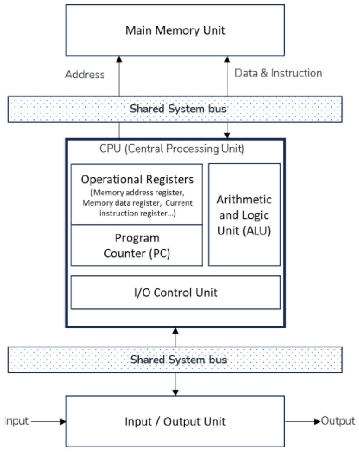
Indeed, such digital systems make use of real time embedded operating system with different strategies of memory allocation and execution for cyclic tasks, which monitor I/O (Input/Output) of the process. They are computer based (i.e., designed mainly according to Von NEUMANN architecture principles as shown in
Figure 1), and their hardware is built around generic microprocessors and associated peripheral components. Their programming is based on a dual software architecture where an operational system software (operating system) is used to coordinate different parts of the hardware and support the execution of the I&C (Instrumentation & Control) functions, which are designed and implemented separately as the application software using either general purpose languages such as C or Ada, application-oriented languages such as function block diagram languages (refer to those defined by IEC 61131-3) with their associated code generators, or selection / use / configuration of pre-developed software modules [
4].
Regarding the requirements of NPP I&C applications, the Von NEUMANN architecture [
5] has some limitations such as sequential processing of instructions and shared system bus which can be an issue as data and control instructions cannot be obtained simultaneously. The consequence is that the execution of functions (operations and operands) must be statically scheduled as soon as the early design phase activities are completed. Moreover, the unified memory structure can lead to memory corruption since data and instructions reside in the same memory. To overcome these “drawbacks” modern CPUs add additional units such as MMU (Memory Management Unit) to implement memory protection and isolation mechanisms that are handled by a complex real-time operating system, which is used to coordinate and mutually protect concurrent user applications sharing the common resources. Their complexity makes the verification task difficult and time-consuming in the context of safety critical application for NPP.
The V&V of real-time operating system is very difficult, as it needs to get access to the source code, which is the intellectual properties of the system developer and manufacturer. Even when the parties have signed an NDA (Non-Disclosure Agreement), analysing hundreds of thousands of lines of code (e.g., C and assembly languages) is very hard and time-consuming task even assisted by software tools such as static analyser PolySpace
TM (MATLAB).
Model checking of the resulting control system is also part of the V&V activities. This involves exploring all possible states or paths of a model and checking whether they satisfy a given set of properties expected from the control system. It also requires many efforts to build an appropriate model - with the tractable number of states and algorithms, generating an acceptable computation time while remaining able to “identify any objective evidence required to confirm the extent of testing” and justifying “the test coverage criteria chosen according to the design” as required by IEC 60880 standard [
4], keeping in mind that exhaustive checking remains impractical [
6].
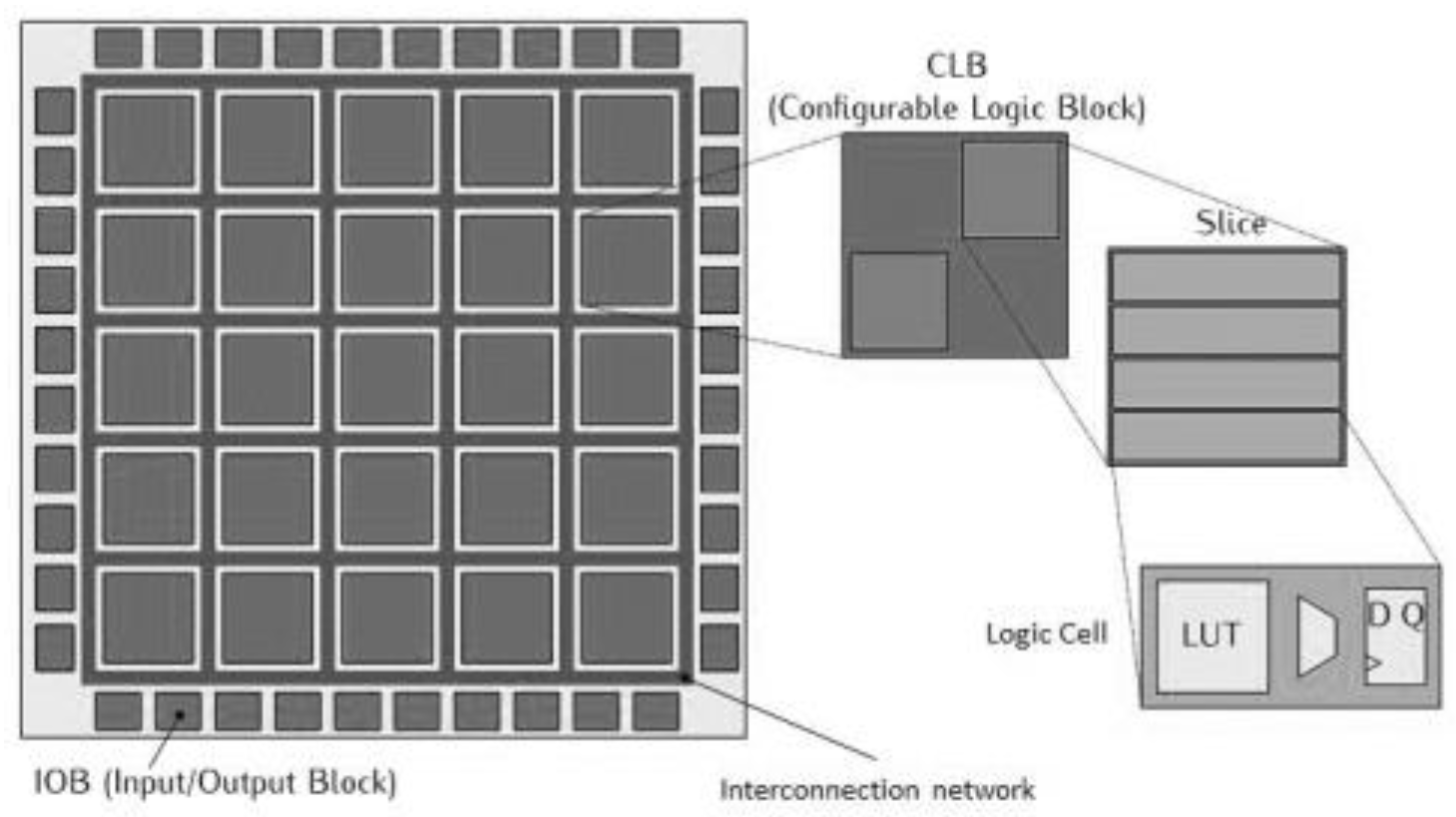
In this paper, we present our exploratory work to find an approach to develop safety functions using a new paradigm that would ease the V&V activities and thus reduce the cost of the safety justification and qualification processes. We demonstrate the relevance of this paradigm by building a channel processing FPGA board that uses pure FPGA architecture (
Figure 2) with native toolchain of FPGA manufacturer to design our safety functions.
FPGA architecture offers several advantages for the V&V of the user application since the implementation of its functionalities consists of interconnecting the available Configurable Logic Blocks (CLB) and Input/Output Blocks (IOB). These CLBs are activated in parallel, and their registers outputs are driven by the FPGA main system clock (e.g., for a synchronous design architecture and paradigm). Practically, the implementation of functionalities in user applications is designed and developed using a Hardware Description Language such as VHDL (Very high-speed integrated circuit Hardware Description Language). This language is part of the IEEE Std 1076-1993 standard which supports the portability of the design. It is complemented by companion standards such as IEEE Std 1076.2, IEEE Std 1076.3 and IEEE Std 1076.6 which describe Mathematical Packages, Synthesis Packages and Register Transfer Level (RTL) Synthesis. VHDL is a strongly typed language that can be used elegantly for developing functions that are activated in parallel. VHDL can also be used to write a functional simulation of the implemented features of the user application. Such capability is very useful because it allows the verification of the specification to be carried out without much effort to ensure that the expected requirements are well specified by the application developers and correctly understood by the other developers (mainly, electronic hardware and system integration) or independent reviewers.
Our paper is organized as follows.
Section 2 introduces the concept of channel (IEC 61508-4) and reviews the main points of the IEC 61513 and 62566 relevant to understand our design approach from system level, especially in the context of Globally Asynchronous Locally Synchronous (GALS) architecture.
Section 3 describes the development lifecycle of the channel processing FPGA board.
Section 4 illustrates the implementation of a simple set of safety functions on the FPGA board. Through the examples, we show that the proposed channel processing FPGA board design provides an elementary “white box” processing module for designing the architecture of a protection system, while supporting V&V activities for Category A functionalities (the most safety-critical ones) as required in the outlook of nuclear power plant environmental and logical qualification (Functional validation, among other main requirements in IEC 61513).
Finally, future works are drawn in section 5.
2. Concepts and Nuclear Standards for the Design of the Channel Processing FPGA Board
International Electrotechnical Commission (IEC) is a global, not-for-profit membership organization preparing and editing international standards for all electrical, electronic and related technologies. IEC hosts numerous technical committees among which TC65 “Industrial-process measurement, control and automation” (for non-nuclear sectors) and TC45 “Nuclear instrumentation” (sub-committee SC45A “Instrumentation, control and electrical power systems of nuclear facilities”).
A first paragraph (§2.1) recalls the main inputs hired from the IEC 61508 series of standards that have founded those “aspects to be considered when electrical/electronic/programmable electronic (E/E/PE) systems are used to carry out safety functions” for the non-nuclear industrial sectors. The remaining paragraphs are dedicated to our application in the nuclear sector.
2.1. Concept of Channel for PE Systems from the “Functional Safety World”
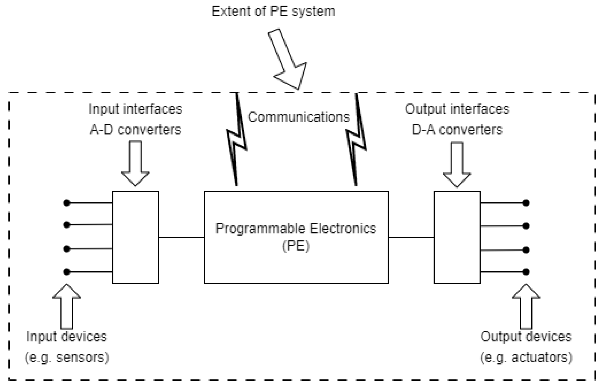
TC65 has defined “Functional safety” as the “part of the overall safety that depends on a system or equipment operating correctly in response to its inputs”. Dealing with programmable electronics (PE) systems (“system for control, protection or monitoring based on one or more programmable devices, including all elements of the system such as power supplies, sensors and other input devices, …, and actuators and other output devices”), IEC 61508 Part 4 [
7] defines channel as “an element or group of elements that independently implement an element safety function”. Those two concepts are illustrated in
Figure 3.
The channel processing concept is particularly useful for risk reduction measures when having to mitigate risk in the event of a channel fault (IEC 61508-4 functional safety standard defines fault as “abnormal condition that may cause a reduction in, or loss of, the capability of a functional unit to perform a required function”). In addition, such a design would facilitate the functional analysis of each independent channel in the V&V activities because each functionality can be associated to a processing channel with its own data and control flows.
2.2. Discussion of the Development of Safety-Relevant Instrumentation and Control Systems Throughout Its Main Nuclear IEC Standards
The development approach must implement the lifecycles recommended in IEC standards 61513 [
8] and 62566 [
12] which deal with the development of instrumentation and control systems important for safety in NPPs, at the overall system level [
8] of the installation on one side, and at the component level of the overall I&C architecture for a system implemented with the FPGA technology and designated as an Hardware Programmable Device (HPD) [
12] on the other side (see paragraph 2.3).
At the system level, the channel processing concept means that there could be as many processing channels as there are independent safety functions to be implemented according to the overall I&C system architecture analysis required by IEC 61513 [
8] (subsets of I&C safety functions to be allocated to the independent lines of defence-in-depth designed by the overall safety assessment process of the global NPP installation, following guidelines by WENRA [
9]).
For the Reactor Protection System (RPS) line of defence-in-depth inside the overall I&C system architecture, we explore the advantage of integrating the channel processing boards into a Globally Asynchronous Locally Synchronous (GALS) architecture.
Programmable Electronics can be implemented using any type of electronic technology whether microprocessor based (Software) or FPGA based (Hardware Description Language). Our work is dedicated to exploring the realization of Programmable Electronics using FPGA technology, keeping verifiability in mind. As mentioned in the introductory section 1, our rationale is that contemporary general-purpose microprocessors have become mostly “grey (complex)/black boxes” and most common programming languages such as C, Ada or IEC 61131-3 were designed for the development of sequential and cyclic execution of user applications. FPGA technology makes it possible to design a Globally Asynchronous Locally Synchronous (GALS) architecture that could stick to the genuine simplicity of the I&C safety functions assigned to each of the elementary PE sub-systems. Our channel processing design approach aims at avoiding the additional complexity factors typically associated with software items of operating system in generic I&C platforms implementing von NEUMANN architecture principles (based on programmed microprocessors or emulating their behaviour).
Moreover, GALS allows designers to partition a large system into several sub modules [
13] and thus build large scale distributed systems with ease of integration and V&V. Metastability risk when communicating between sub-systems synchronized by their own local clock may be mitigated by using an intermediate asynchronous FIFO stage [
13,
14,
15,
16,
17] so that reliable communication between independent / different clock domains can be achieved.
The association of the channel processing design principle with FPGA technology and GALS architecture aim at satisfying those deterministic constraints applicable to I&C (for such tasks as its design process, behaviour assessment or safety case analysis) that are derived from the plant design base. The most important ones required by the IEC 61513 are the single failure criteria for category A functions, functional isolation and independence between systems allocated to different lines of defence-in-depth or ranked to a lower importance for safety as defined by IEC 61226 [
10].
2.3. IEC 62566 Complements IEC 61513 for the Development of Safety-Relevant Instrumentation and Control Systems Using FPGA Technology
Due to the increasing use of FPGA technology in many application domains and despite its legendary caution towards new technologies justified by the overriding genuine concern for safety upon all other considerations, the nuclear sector community began to consider its potential for dealing with long-term support over extended plant lifetimes issues such as component obsolescence and replacement or upgrade of existing analogue and digital I&C systems. Additionally, FPGA based systems may provide solutions to diversity requirements when it is appropriate (e.g., adequately justifiable, especially in comparison with microprocessor and software-based systems).
In this trend and according to its mission (promoting cooperation among the stakeholders for the safe, secure and peaceful use of nuclear technology), the International Atomic Energy Agency (IAEA) decided to help plant owners, suppliers, regulators and researchers join their efforts as a nuclear industry. Consequently, the “First Workshop on the Applications of Field Programmable Gate Arrays (FPGA) in Nuclear Power Plants” was held on October 2008, hosted in Chatou (France) by the R&D Division of EDF power generation company, and co-sponsored by the IAEA [
11].
In the meantime, IEC SC 45A experts of the working group in charge of Instrumentation & Control (architecture and system specific aspects) had established the foundation of the IEC 62566 standard [
12], published by the IEC in 2012, which defines the requirements and recommendations on:
A dedicated development life cycle of HPD (HDL – Hardware Description Language – Programmed Device: HPD is an integrated circuit configured for NPP I&C systems with Hardware Description Languages such as VHDL) including specification of requirements, design, implementation, verification, integration and validation phases (final step of validation testing being performed on the overall I&C system in its final assembly configuration including the validated version of the HPD).
“Planning and complementary activities such as modification and production”.
“Selection of pre-developed components” which include “a blank FPGA or CPLD, HDL statements representing Pre-Developed Blocks” (PDBs).
“Use of simplicity and deterministic principles” to achieve “fault free” implementation of category A I&C functions as defined by IEC 61226 [
10]. This category addresses any function that plays a main role in insuring nuclear safety. The failure of such function “could directly lead to accident conditions”. Category A function is associated to a Class 1 system which corresponds to “Safety Class 1” as defined in IEC 61513 [
8] and IAEA SSG-30 [
18]: “Any Structure, System and Component (SSC) whose failure would lead to consequences of ‘high’ severity”. Typical Class 1 Instrumentation and Control (I&C) Systems deal with reactor protection, safety actuation and key instrumentation and displays enabling operators to take pre-planned actions necessary to ensure the safety of NPP.
“Tools used to design, implement and verify HPDs”.
IEC 62566 complements IEC 61513 by covering any HPD project within the overall I&C system. It focuses on the HPD development life cycle which structures the project to implement the expected safety function logic allocated to the HPD device. The aim of this standard is to avoid as far as possible latent faults remaining in HPDs and to reduce the susceptibility to single failure and potential common cause failure as defined in IEC 61513 standard (i.e. failure of two or more structures, systems or components due to a single specific event or cause).
In terms of quality assurance plan and configuration management, IEC 62566 follows the requirements of IEC 60880 [
4] by replacing “software” with “HPD”. In particular, “the configuration management shall record the following items: a) documentation of modules (blocks) developed within the project and of Pre-Developed Blocks; b) identification marking of integrated circuits; c) computer files used for simulation, verification and production; d) parameters used for the automated activities of the software tools…, such as optimize timing, optimize density for the Place and Route activity; e) identification of the versions of all software tools…, as well as general purpose libraries and technology dependent libraries”.
2.4. A Recommended Development Life-Cycle of HPD Which Helps Justify the Correct Operation Expected from a Class 1 System
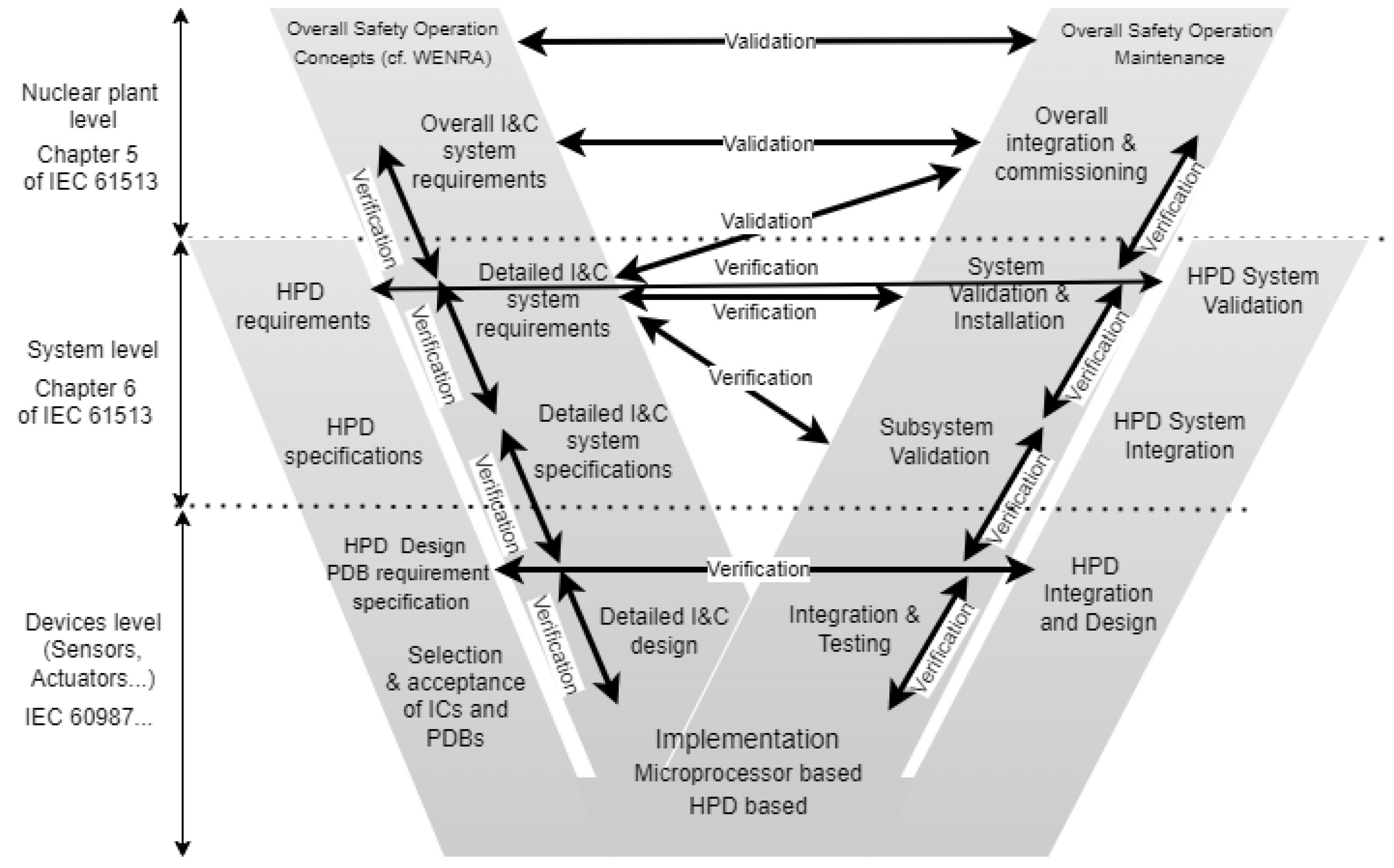
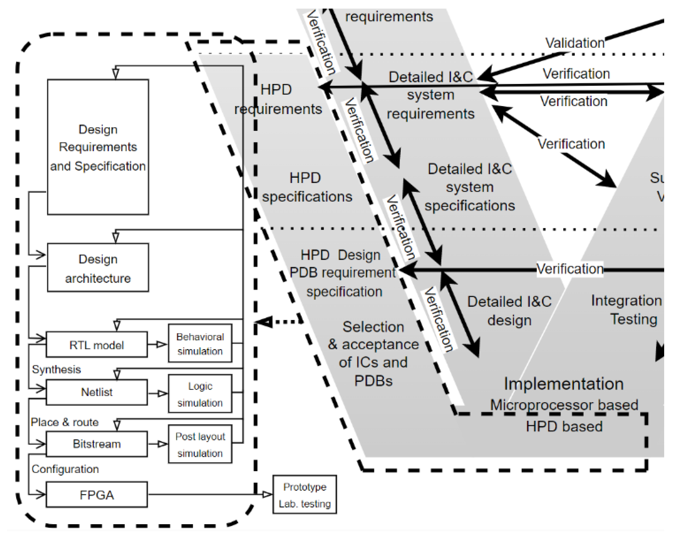
IEC 61513 has defined the process for developing I&C systems for use in NPP. IEC 62566 provides additional guidance regarding V&V activities during the lifecycle of an HPD project. The recommendations on the V&V activities are attached to the “Detailed I&C system specifications” step of the IEC 61513 “V-model” as shown in
Figure 4 (noted as “inner V” cycle).
We apply IEC 62566 guidance and recommendations in addition to the ones suggested by IEC 61513 which concern only microprocessor/software-based implementation of safety functions. The IEC 62566 standard is much more dedicated to the development of safety functions based on FPGA circuits as shown in
Figure 5.
The workflow on the left-hand side of
Figure 5 is the usual development methodology of FPGA based application for I&C functions. The IEC 62566 recommendations emphasize on the verification and validation stages by an independent team (especially for Category A functions) throughout the usual development cycle regarding the requirements, the specifications, and the detailed design.
In the following section, we present the development of simple safety I&C functions during the successive stages of an HPD project which is based on our channel processing FPGA board. This one was carried out as part of an earlier HPD project, described in the following paragraph.
3. HPD Project of the Channel Processing FPGA Board
To develop our simple safety functions, we designed a channel processing FPGA board that emphasizes the segregation of independent safety functions.
HPD Design Requirements Specification:
Ten analog inputs for 4/20mA current loop from sensors.
Five digital inputs for On/Off switch/Control button (dry loop).
Five digital outputs (dry loop)
One analog output with 4/20mA current loop which is powered by a 24VDC supply.
Analog-to-Digital and Digital-to-Analog converter with 16-bit resolution.
Low power consumption FPGA with:
Flash for application configuration parameters,
Thousands of Logic Elements for the design of simple to low complexity functions.
The whole FPGA board should be powered by an external 5VDC.
Selection and acceptance of ICs and PDBs:
- j.
Intel Altera MAX 10 FPGA family from Terasic DE10-Lite board clocked at 50 MHz with 50K LEs.
- k.
Texas Instruments ADS114S08 ADC.
- l.
Analog Devices AD5660 DAC and AD5750 voltage-to-current (4..20mA) converter.
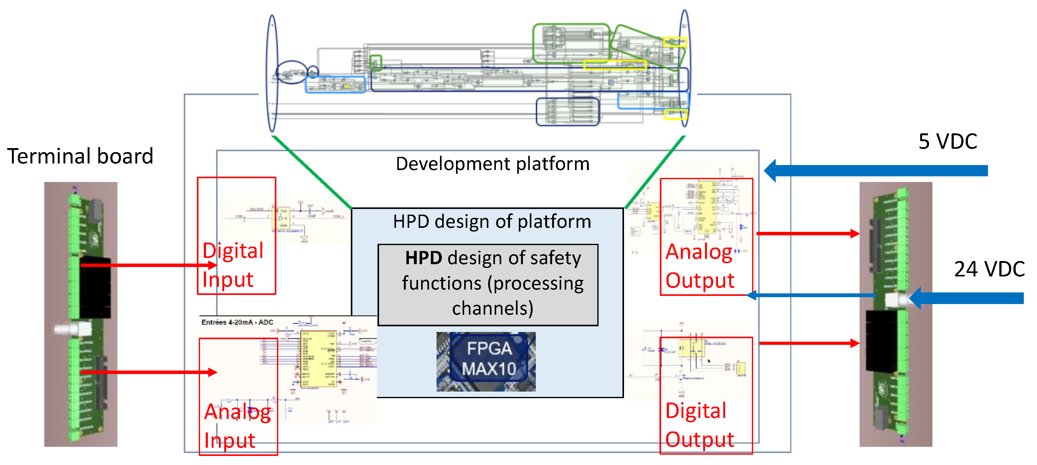
The schematic diagram of our FPGA board is shown in
Figure 6.
The channel processing board refines the PE system concept discussed in the previous section (see §2.1). Its architecture includes an A-D converter, an FPGA circuit and a D-A converter which form a complete PE system for developing the functionalities required by the safety application.
From a reliability point of view, this design choice has the advantage that the single point of failure is restricted to the FPGA itself as an integrated circuit configured with the set of safety functions assigned to it. This kind of implementation does not introduce any additional dependency between those functions that their specification has required to be independent.
Our channel processing FPGA board is modular enough to be used as the basis for building a larger control/protection system by integrating it into a rack in which each channel processing FPGA board is dedicated to an independent and functionally coherent subset of safety functions. GALS architecture can thus be implemented to design a more complex or complete protection system.
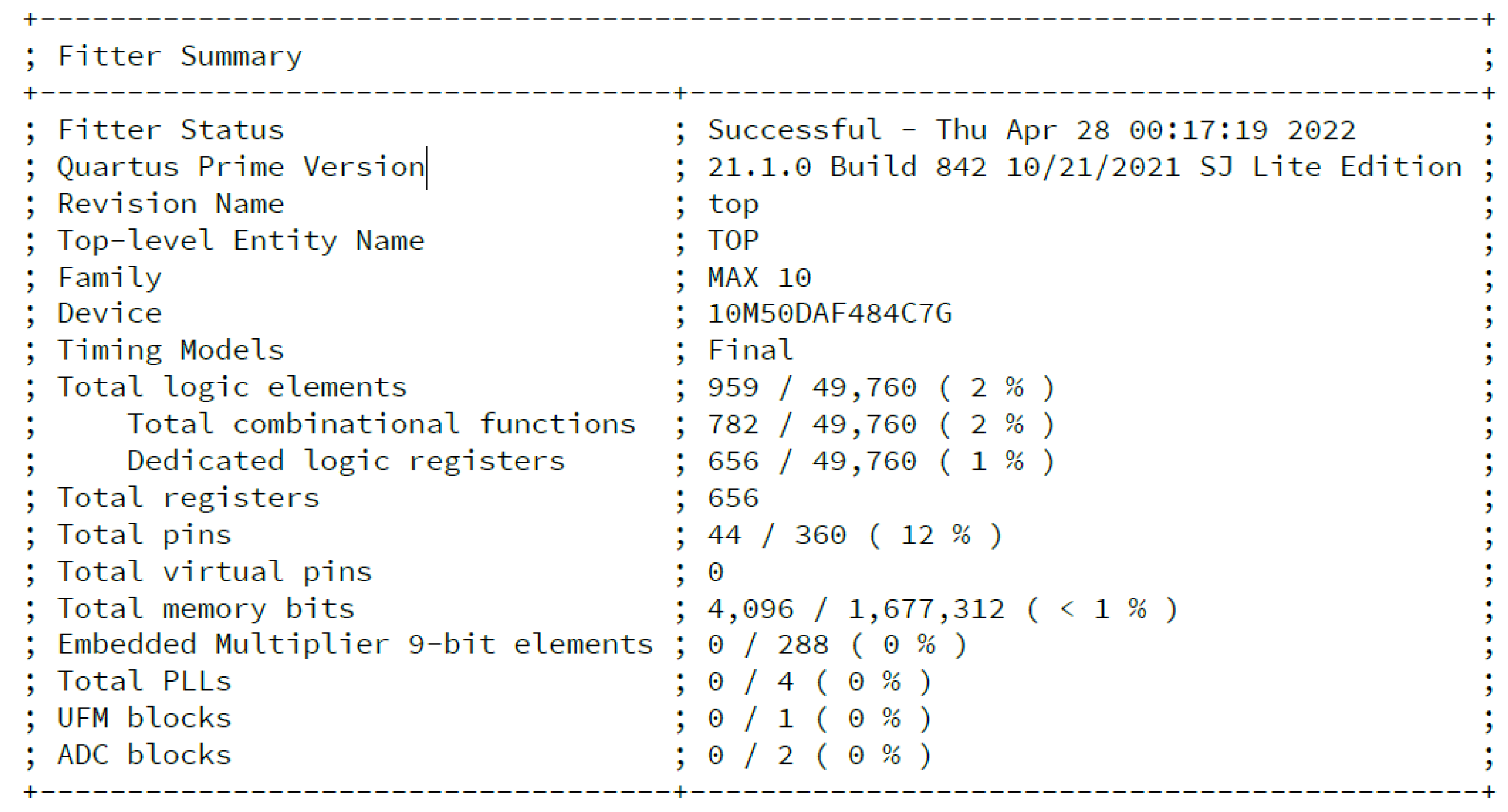
In terms of resources, this part of the HPD project (channel processing FPGA board) uses 959 Logic Elements (LEs) out of a total of 49760 LEs as shown the
Figure 7. The remaining LEs are used to develop safety applications/functions (see section 4).
4. HPD Project of Simple I&C Safety Application Functions
As mentioned in the previous sections, our development of safety functions is based on pure FPGA architecture. This means we use neither the softcore processor nor the microprocessor emulation approaches, which generally perform cyclic, sequential scheduling of tasks as conventional (e.g. Von NEUMANN architecture) computer based do. One of the disadvantages of these approaches is that cycle execution times increases with the number of tasks to be performed sequentially. In addition, they require optimizing the allocation of safety functions according to the resources available on the microprocessor or softcore, to ensure that the cyclic execution time of tasks respects the functional performance requirements (e.g., response times, …).
Using the native VHDL capabilities to configure the native FPGA resources for the implementation of safety functions offers several advantages:
Parallel execution of safety functions without being impacted by the number of tasks to be performed.
Avoid the single point of failure among specified independent safety functions that results from the failure of a shared resource (e.g. memory, microprocessor and operating system) introducing additional complexities unnecessary for the implementation of those safety functions.
Simplify and concentrate V&V activities on both HPD projects (the electronic support system and the application-specific I&C safety functions), which use only Configurable Logic Blocks (CLBs) and auxiliary electronic components (e.g., ADC, DAC…) embedded with the chosen FPGA integrated circuit on the board.
The contribution of our paper is to emphasize that the development of safety functions based on the native capabilities of FPGA – VHDL, with the advantages mentioned above, reduces the complexity in V&V activities throughout the nested “V-models” of IEC 61513 and IEC 62566 discussed at the end of section 2.
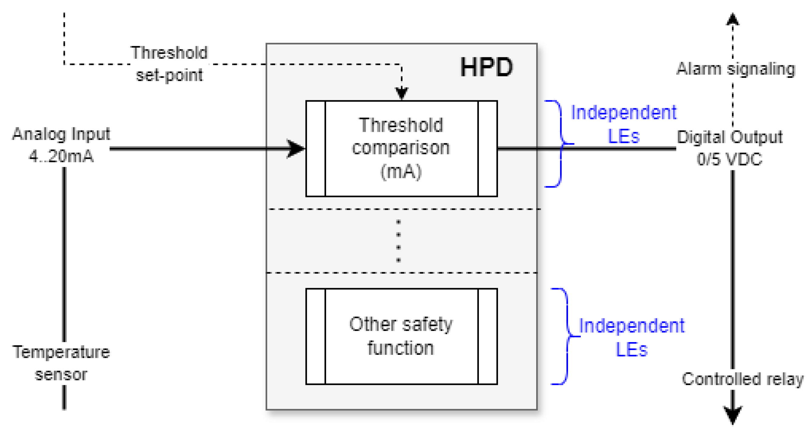
Many I&C safety application functions are based on simple monitoring of a process parameter (typically an analog input from a 4-20mA current loop), and action is taken when a threshold is reached. We propose to illustrate the implementation of such functionality in our HPD project.
The high-level block diagram in
Figure 8 illustrates the processing channel principle, which guarantees the processing independence of this simple threshold function compared to a microprocessor-based development.
The HPD design requirements are the following:
Threshold comparison with a pre-defined value.
Comparison processing every clock tick of 1 second.
Analog input signal from 4/20 mA current loop connected to a sensor.
Digital output signal: 0/5 VDC for alarm signalling or controlled relay.
4.1. Design of Threshold Comparison Function (Entity BF6) Using Intel QuartusTM with Questa IntelTM Starter FPGA Edition
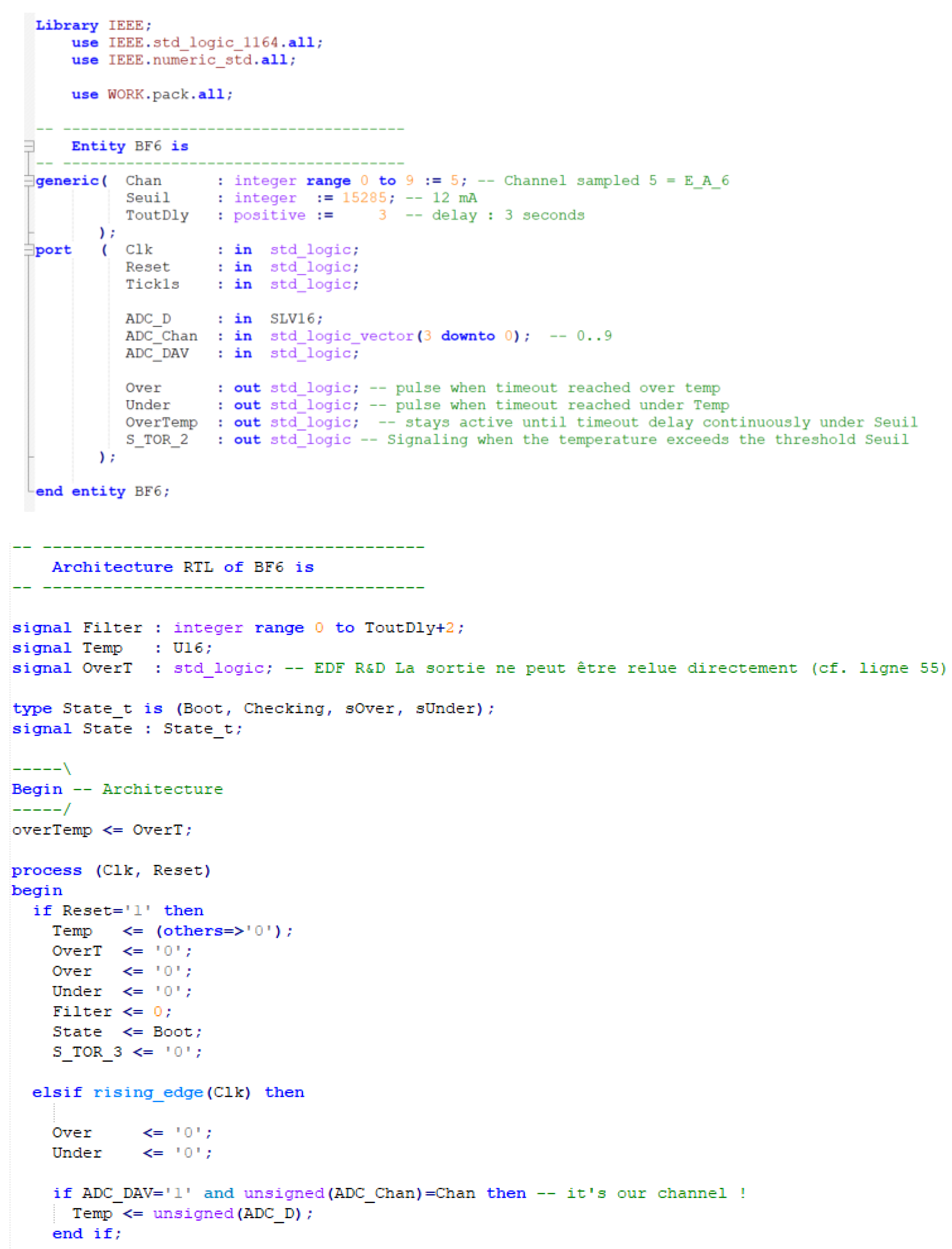
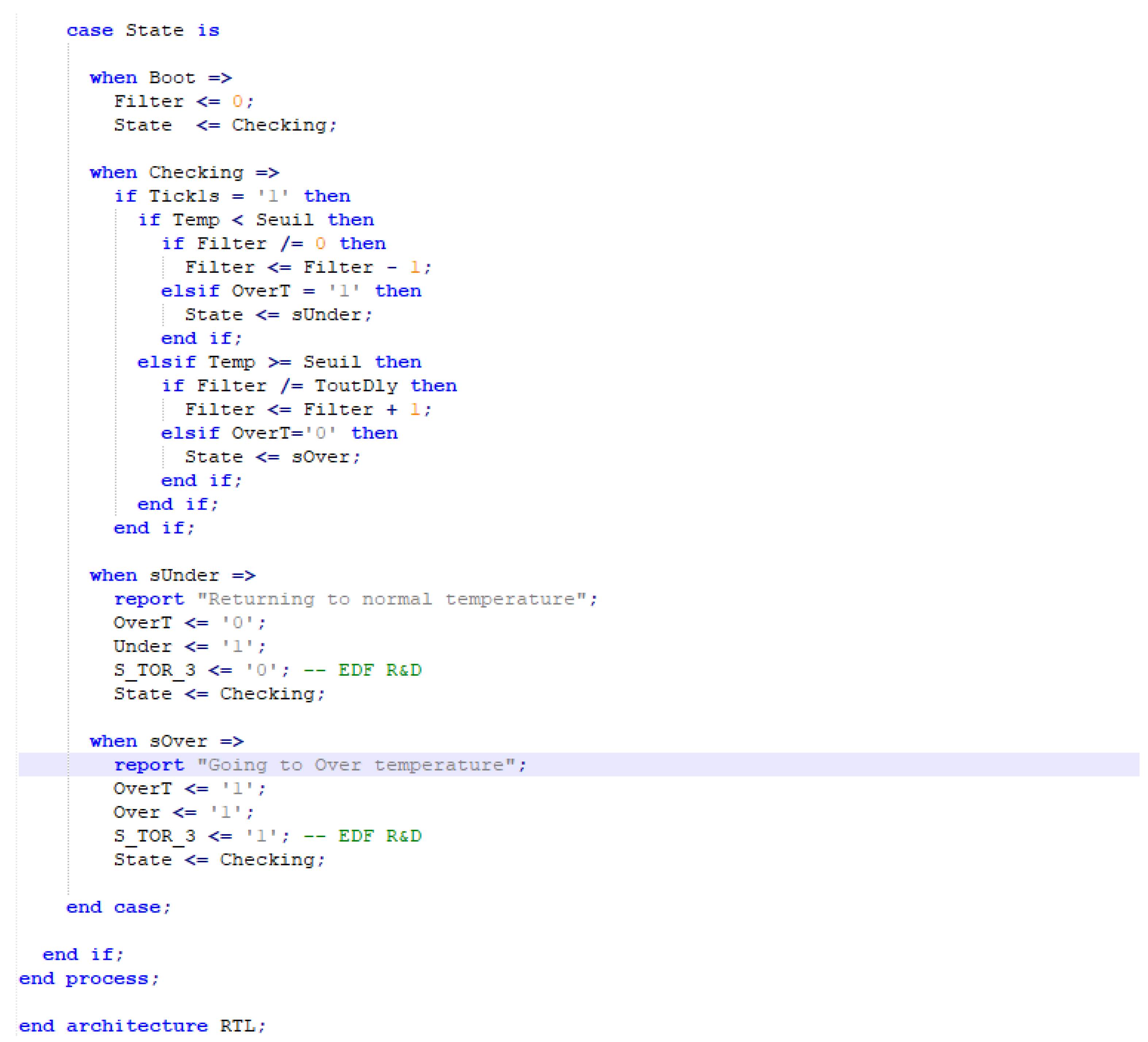
The top-level of our HPD project contains various safety functions. It is beyond the scope of this paper to describe all the safety functions in detail, instead we will briefly present the threshold comparison function called “BF6” in our project. The following
Figure 9 shows the definition of Entity BF6 and its behavioural architecture.
4.2. V&V of BF6 Module
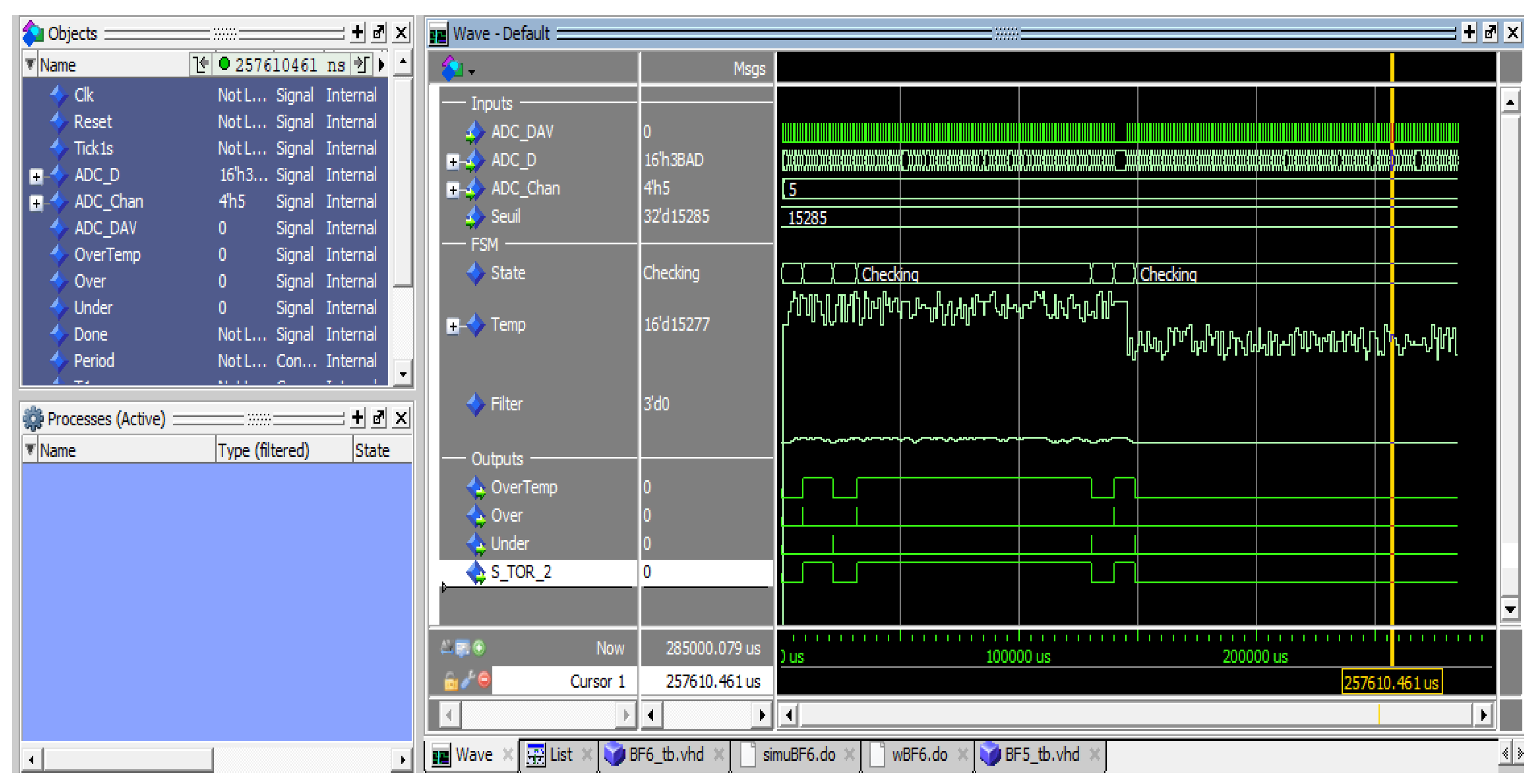
We performed the V&V (behavioural unit testing and functional simulation tests) of BF6 using Modelsim
TM Starter Edition running a test bench script which produces the solicitation of the safety function and observes the output waveform of S-TOR-2, a digital output used for controlling a relay or signalling an alarm (
Figure 10).
There is no added value to present Logic simulation and Post layout simulation for this simple functionality, but it is worth to present further verification by connecting the proof-of-concept to different physical test benches in the following paragraph.
4.3. Performing Further Verification of the Implementation by Connecting the Platform to Different Physical Test Beds
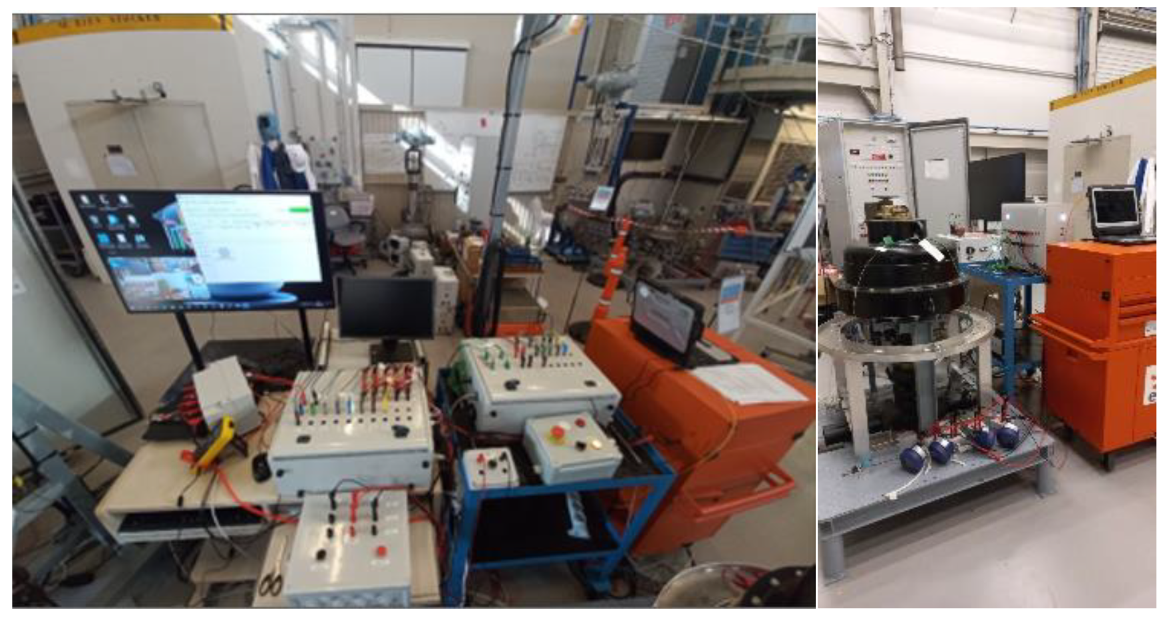
We have developed two physical test benches for the verification of our HPD project. The first consists of various digital and analog signal generators which inject the solicitation waveforms into our development platform (safety I&C engineering workstation), as illustrated in the following figure (
Figure 11).
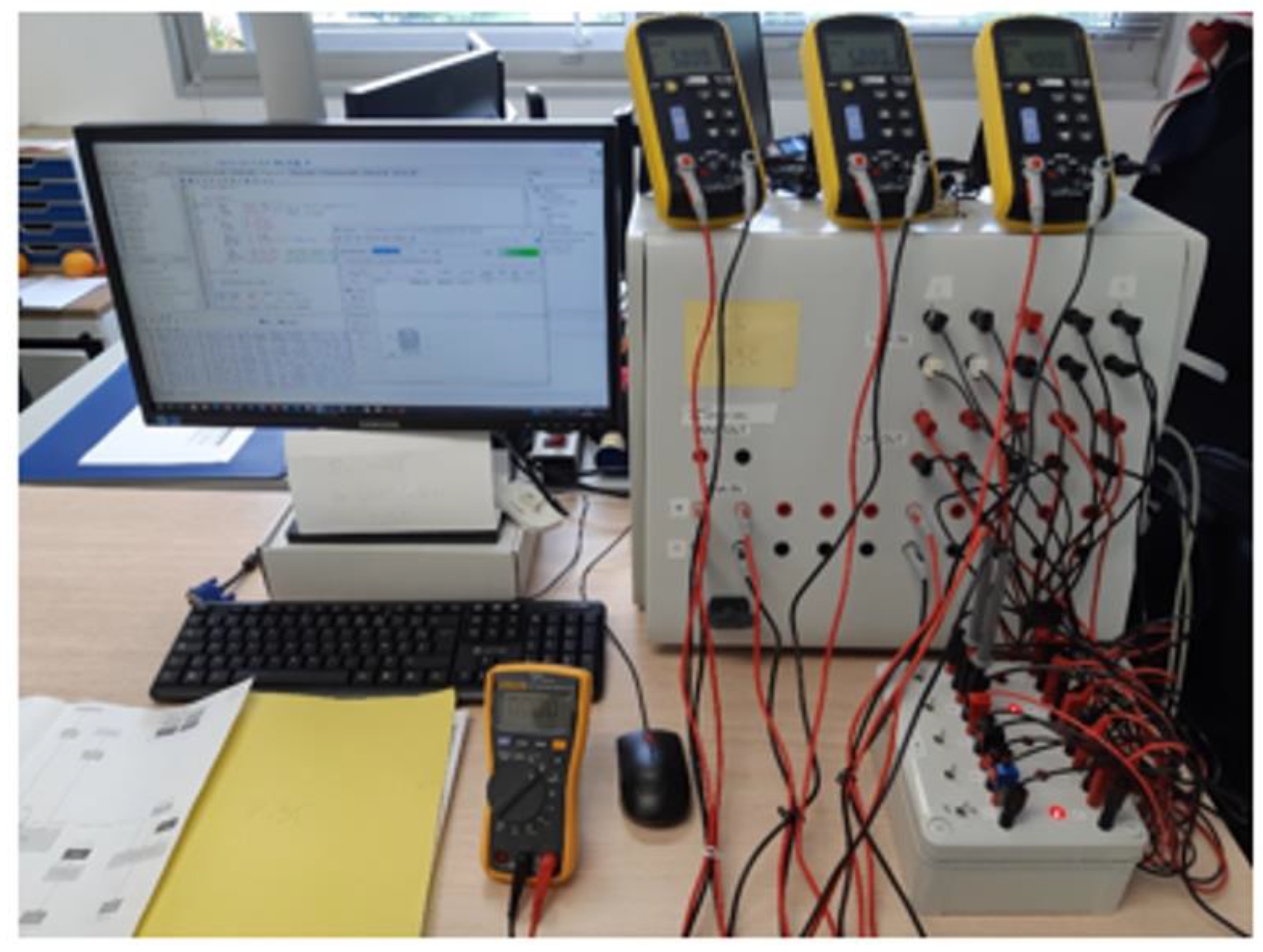
When all expected behaviours were achieved on this host Test bench environment and the HPD validation phase completed, we connected our HPD system to real sensors and actuators in one of our laboratory facilities dedicated to research and development of valves applications (static and dynamic testing of their components or materials, as preliminary investigations supporting their qualification process) for EDF NPP installations as presented in the
Figure 12.
A thermocouple is connected to an analog input of our HPD system, when the generated current loop is exceeding 12mA, a digital output of our HPD system raises to high level (in case of an energized logic); which controls then a relay to open a On/Off valve for a given process control circuit.
5. Conclusions and Future Works
In this work, we have demonstrated a proof-of-concept for experimenting the shift from the traditional computer-based architecture paradigm (microprocessor / memory / software) to a new one based on the use of native HDL capabilities to configure a native FPGA resource to implement I&C safety functions allocated to a nuclear reactor protection system. During our work, we have shown how to apply different the main nuclear safety standards, in particular IEC 61513 and IEC 62566, in the development lifecycle.
We have been able to experience both roles of developer and “independent” verifier to better identify the necessary formalized interactions during constructive design activities and their verification counterpart at each phase of the whole lifecycle of the nested-“V-model”. We addressed the main issue of elaborating a claim / argument / evidence structured justification scheme throughout the development steps and have established the feasibility of the FPGA channel processing board at least for simple I&C safety functions.
Our future works will focus on the performance assessment of the FPGA channel processing board in terms of computation of more complex safety functions such as the implementation of smart actuators adding self-monitoring and diagnostic capabilities while keeping the priority of preventing issues such as CCF and cybersecurity. We keep on investigating the design of a GALS architecture for a safety critical I&C system application that could take advantage of its simplicity, notably to facilitate the safety case of some other applications.
References
- Chen, R.; Wu, T.; Zheng, Y.; Ling, M. MLoF: Machine Learning Accelerators for the Low-Cost FPGA Platforms. Appl. Sci. 2022, 12(1), 89. [CrossRef]
- M. Elnawawy, A. Farhan, A. A. Nabulsi, A. R. Al-Ali and A. Sagahyroon. Role of FPGA in Internet of Things Applications. IEEE International Symposium on Signal Processing and Information Technology (ISSPIT), Ajman, United Arab Emirates, 2019, pp. 1-6, https://doi: 10.1109/ISSPIT47144.2019.9001747.
- Magyari, A.; Chen, Y. Review of State-of-the-Art FPGA Applications in IoT Networks. Sensors 2022, 22(19), 7496. [CrossRef]
- IEC 60880, "Nuclear power plants - Instrumentation and control systems important to safety - Software aspects for computer-based systems performing category A functions", Edition 2006.
- Sacha Krakowiak. "Le modèle d'architecture de von Neumann", https://interstices.info/le-modele-darchitecture-de-von-neumann/, November 2011.
- Mordechai Ben-Air. A Primer on Model Checking - extended papers. ACM Inroads 2010 March Vol.1, No 1. [CrossRef]
- IEC 61508 Part 4, “Functional safety of electrical/electronic programmable electronic safety-related systems – Part 4: Definitions and abbreviations”, Edition 2 2010.
- IEC 61513, "Nuclear power plants - Instrumentation and control important to safety - General requirements for systems", Edition 2011.
- Western European Nuclear Regulators Association (WENRA) / Reactor Harmonization Working Group (RHWG), “Report on Safety of new NPP designs”, March 2013.
- IEC 61226, "Nuclear power plants - Instrumentation, control and electrical power systems important to safety - Categorization of functions and classification of systems", Edition 4.0 2020.
- "Workshop on the Applications of Field-Programmable Gate Arrays (FPGA) in Nuclear Power Plants", (IAEA - Department of Nuclear Energy) Nuclear Power Newsletter, Vol. 5, No. 4, December 2008.
- IEC 62566, "Nuclear power plants - Instrumentation and control important to safety - Development of HDL-programmed integrated circuits for system performing category A functions", Edition 1 2012.
- Frank Kagan Gürkaynak’s Ph.D Thesis. GALS System Design: Side Channel Attack Secure Cryptographic Accelerators, ETH Zurich, November 2005.
- Atanu Chattopadhyay and Zeljko Zilic, GALDS: A Complete Framework for Designing Multiclock ASICs and SoCs, IEEE Transactions on VLSI Systems 2005, Vol. 13, No. 6, pp. 641-654. [CrossRef]
- L. P. Carloni, K. L. McMillan, and A. L. Sangiovanni-Vincentelli, ‘‘Theory of Latency-Insensitive Design,’’ in. IEEE Transactions on Computer Aided Design of Integrated Circuits and Systems, 20(9) :18, Sept. 2001.
- Pierre Bomel and Eric Martin, Emmanuel Boutillon : Architecture de wrapper de synchronisation pour environnement de type GALS/LIS, LESTER, UBS, Lorient, France, Journées Francophones en Adéquation Algorithme Architecture, Jan 2005, Dijon, France. pp.JFAAA 2005.
- Milosˇ Krstic´ and Eckhard Grass, Frank K. Gürkaynak, Pascal Vivet: Globally Asynchronous, Locally Synchronous Circuits: Overview and Outlook, IEEE Design & Test of Computers 2007, Vol. 24, Issue 5, pp. 430-441. [CrossRef]
- IAEA Specific Safety Guide, No. SSG-30, "Safety Classification of Structures, Systems and Components in Nuclear Power Plants", May 2014.
|
Disclaimer/Publisher’s Note: The statements, opinions and data contained in all publications are solely those of the individual author(s) and contributor(s) and not of MDPI and/or the editor(s). MDPI and/or the editor(s) disclaim responsibility for any injury to people or property resulting from any ideas, methods, instructions or products referred to in the content. |
© 2024 by the authors. Licensee MDPI, Basel, Switzerland. This article is an open access article distributed under the terms and conditions of the Creative Commons Attribution (CC BY) license (http://creativecommons.org/licenses/by/4.0/).
