1. Introduction
In the last decades, aviation is moving towards electrification to face climate change issues and improve aircraft performances. In particular, new electric components are being introduced to replace non-propulsive subsystems currently driven mechanically, hydraulically and pneumatically to improve subsystems efficiency. Moreover, several studies and efforts are underway to partially or totally replace Internal Combustion Engines (ICEs) with new propulsion systems, such as hybrid electric or fully electric systems.
The introduction of hybrid electric propulsion opens new potentialities and generates new challenges, such as the way to dissipate produced heat. Hybrid electric power-unit, in fact, have strict thermal constraints that cannot be matched by using conventional cooling techniques currently used in modern aircraft. This is mainly due to insufficient physical properties (e.g. heat transfer capacity) of traditional coolants (air, water, lubricants, etc.) but also to size, weight and thermal constraints. Therefore, several studies are focusing on defining new cooling technologies to ensure the safe operation of hybrid power plants. In particular, a promising research field is linked to the so called nanofluids (NFs), colloids composed of nanoparticles added to a base fluid, which is generally water, due to its superior properties (availability, environmental friendliness, high thermal conductivity, and low cost) [
2]. Nanofluids offer potential benefits for thermal management systems in aircraft, but come with some challenges concerning:
stability – nanoparticles tend to agglomerate, impacting fluid stability, which is essential for the reliable performance of TMSs [
3,
4];
properties variability – nanofluids physical properties (e.g. thermal conductivity) reported in literature vary significantly [
5];
mechanisms and forces uncertainty – the forces acting on nanoparticles during suspension and after deposition are not completely clear; in fact, several researchers continue to explore this topic [
6,
7,
8];
pressure drop and pumping power – higher flow rates enhance heat transfer but also increase pressure drop and pumping power; the balancing of these factors is crucial for the proper implementation of nanotechnology [
9,
10,
11,
12].
Despite these challenges, nanofluids are believed to have a high potential to improve TMS and are considered a promising solution for various applications. One notable success is the use of nanofluids in Spacecraft Active Thermal Control Systems (ATCSs). The improved heat transfer efficiency of nanofluids has allowed for a reduction in system volumetric flow rates and pumping power requirements [
13]. Another promising application consists of the use of alumina-based nanofluids in combination with deionised water for the cooling of military aircraft. These aircraft require extremely efficient coolants to manage heat dissipation, and nanofluids have shown great potential in this regard [
14].
The Italian Aerospace Research Centre (CIRA) has developed, as part of the European research initiative ORCHESTRA, a TMS based on impinging jets technology for a 1 MW electric motor which is fully described in [
1]. CIRA is also contributing to the development and maturation of technologies for the next generation regional aircraft, not only by participating in European-funded projects but also by launching projects under the umbrella of the national aerospace research program PRO.R.A. In this latter framework, the ELECTROPLANE project was conceived to explore the main technologies that make adopting hybrid electric propulsion systems possible, including those relating to the cooling of high-power electric motors. Therefore, the TMS designed for the ORCHESTRA project has been exploited to study the potential of nanofluids by considering two nanoparticles, alumina and graphite, in two different configurations of molecular structure, and their concentrations in the range from 1% to 10% of diathermic oil volume fraction.
This work develops according to the following structure: after recalling the state-of-the-art cooling technologies, the objective of this work is defined, and the TMS of the electric motor is described. Subsequently, the nanoparticles added to the base fluid are characterized by thermophysical properties. The numerical methodology applied to carry out the simulations is detailed before showing and commenting on the results.
2. Background and State of the Art
The closed-cycle gas turbine was first patented by J. Ackeret and C. Keller in 1935. Since then, several progress has been made in this technology, but today, limited improvements can be obtained by optimising state-of-the-art (SoA) engines [
15,
16]. Thus, new propulsion systems like hybrid-electric and full-electric power units are being developed. One of the main issues of such systems is the huge amount of heat to dissipate, which makes mandatory the use of advanced TMSs, such as the ones based on nanofluids, which were introduced by Masuda in 1993 [
17] and named by Choi and Eastman in 1995 [
18]. Nanofluids have significantly enhanced heat transfer characteristics compared to their conventional counterparts [
19,
21] and offer lightweight, high-strength, and durable properties, critical factors for aerospace applications. Thus, they have been applied in different fields, such as aerospace, energy, electromechanics and biomedicine [
21].
2.1. Brief Overview of Thermal Management Systems (TMSs) for Electric Motors
Hybrid/electric power units are gaining prominence in aeronautics due to their environmental benefits and efficiency. Such systems need proper and innovative TMSs for their reliable operation.
Here below is a short overview of possible technologies applicable to electric motors in the aeronautics sector:
liquid cooling [
1]: such systems use coolant (usually water, oil, or a mixture) circulating through channels and/or pipes around critical motor components to remove heat. Such a system is efficient and has a high Technology Readiness Level (TRL=7), but requires additional weight and space.
Refrigerant Assisted Cooling (RA) [
22]: such systems combine traditional air cooling with a refrigerant-based system. RA Cooling, in fact, uses airflow and a secondary refrigerant to enhance heat dissipation, improving cooling efficiency without adding significant weight.
heat exchangers [
22]: they transfer heat between different fluid streams (e.g., coolant and air), enhancing overall thermal efficiency by optimizing heat exchange. They can be compact and lightweight.
skin heat exchangers [
1]: this type of system involves integrating cooling channels into the aircraft’s outer surface to dissipate heat. These systems minimize additional components.
Vapor Cycle Systems (VCS) [
23]: VCS uses a refrigerant cycle to manage heat. They are usually used for cabin cooling but can also be adapted for motor cooling. VCS systems are efficient but may add complexity.
2.2. Impinging Jets Technology
Impinging jets technology is based on a high-velocity fluid jet (usually a liquid or a gas) striking a solid surface. The impact of the jet on the surface creates intense heat transfer, due to the rapid mixing of fluid particles near the surface. The interaction of the jet with the surface depends on several factors, such as the Reynolds number, the Prandtl number and the nozzle-to-wall distance [
24,
25,
26,
27,
28].
Jet impingement systems can be classified as [
29]:
The selection of liquid jet impingement type depends on the industrial application: impinging jets have been applied in cooling systems (mainly electronics, gas turbines, and engine components), for fire suppression (controls flames and cools surfaces), in the food industry (improve coating, drying and sterilization), and manufacturing (to cool-down hot surfaces during metal processing).
2.3. Nanofluids Overview
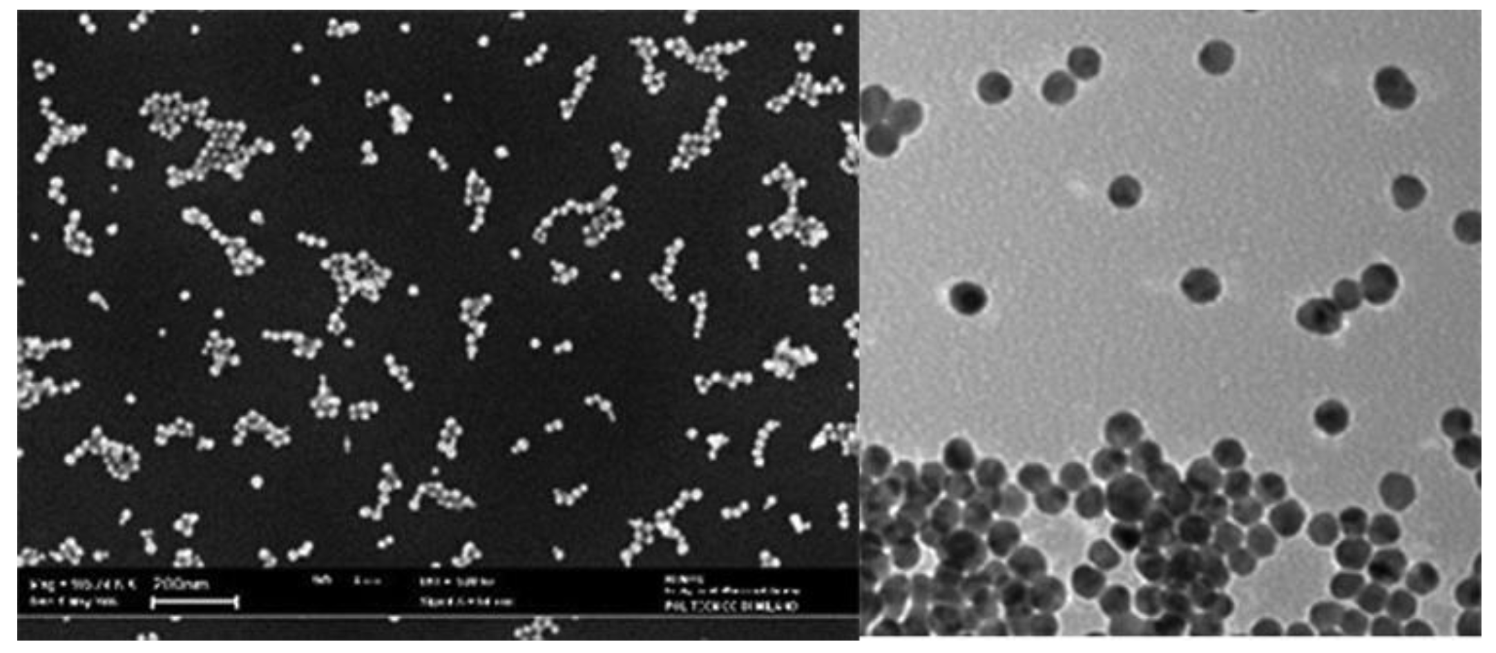
Nanofluids are composed by nanoparticles, metal or polymer particles of small dimensions (ranging from 1 nm to 100 nm) immersed in a base liquid (typically water).
Figure 1.
Nanofluids at microscope (taken from [
32]).
Figure 1.
Nanofluids at microscope (taken from [
32]).
Nanofluids can be used as coolants in systems with high heat-dissipation requirements, such as food processing, nuclear reactors, oil recovery and solar energy collection.
In fact, the introduction of nanoparticles in the base fluid improves the mixture's heat transfer capability, even due to the motion of immersed particles and their collisions with each other and with the wall.
Several authors have applied molecular dynamics to analyse the heat transfer mechanism of nanofluid. In particular, Frank [
33,
34] has established that increasing the strength of the solid-liquid interface reduces thermal resistance.
Papanikoulaou [
35] analysed surface roughness effects on nanoflows, demonstrating that the flow velocity near the wall was reduced with an increasing roughness depth.
Liu [
39] explored the transport and structural characteristics of water inside nanotubes. He found that thermal conductivity and shear viscosity increased as the pore size decreased.
McGaughey [
39] analysed the heat transport mechanism of silica-based crystals, finding that thermal conductivity is related to the scale and temperature of the atomic structure of silica-based crystals.
Sun [
38] studied the force profiles of nanoparticles and base fluids by using the colloidal probe technique. The results showed that the measured and calculated force curves exhibited an evident slip (10–14 nm).
2.4. Nanoparticles for Thermal Management: Advantages and Challenges
Nanofluids are gaining significant importance in the field of thermal management systems due to their enhanced thermal properties: They exhibit superior thermal conductivity, convective heat transfer coefficients, and stability compared to conventional coolants. However, their application presents some challenges. This section is intended to briefly describe both the advantages and the challenges linked to using nanofluids.
- 1)
-
Advantages: one of the most important advantages of nanofluids is their enhanced thermal conductivity. The immersion of nanoparticles, such as metals, metal oxides, or carbon-based materials, significantly increases the base fluid's thermal conductivity. This enhancement is linked both to the high thermal conductivity of the nanoparticles themselves and to the increased surface area for heat transfer. The increased thermal conductivity of nanofluids allows them to achieve higher heat transfer rates, making such types of coolant suitable for applications requiring efficient thermal management, such as automotive cooling, electronic cooling, and industrial heat exchangers [
39].
Nanofluids also exhibit higher convective heat transfer coefficients. This is due to both the increased thermal conductivity and the Brownian nanoparticles’ motion, enhancing energy exchange within the coolant. This property is mostly beneficial in applications involving forced convection, where the fluid is actively circulated to dissipate heat. For example, cars radiators size and weight can be reduced without affecting cooling system performance [
40].
Another advantage of nanofluids is that they require reduced pumping power. In fact, due to nanofluids’ enhanced heat transfer properties, they can achieve the requested cooling effect at lower flow rates compared to conventional fluids. This flow rate reduction translates to lower pumping power requirements, with the consequent energy savings and reduced operational costs. Moreover, nanofluids can reduce pressure drop and flow resistance issues, further optimizing TMS performance [
41].
- 2)
Challenges: nanofluids stability is one of their main concerns. Nanoparticles tend to agglomerate over time, leading to sedimentation and a consequent decrease in thermal performance. To reduce this problem is possible to use surfactants or surface modifications, which could make more complex the preparation process and increase costs [
42].
Another aspect to consider is the potential for erosion and abrasion. The presence of solid nanoparticles in the fluid, in fact, can cause wear and tear on the components of the thermal management system (pumps, pipes, and heat exchangers). This problem is particularly marked in systems with high flow rates or turbulent flow conditions and can lead to increased maintenance requirements and reduced system lifespan [
43].
Furthermore, nanofluids thermal conductivity enhancement is not always consistent among different studies. Variations in nanoparticle type, size, concentration, and base fluid, in fact, can result in differing thermal performance outcomes. Thus, it is requested to further study the underlying mechanism governing nanofluids and to standardise their use [
39].
2.5. Nanofluids for Impinging Jets
Impinging jets can employ different working fluids, including nanofluids, that could be used to improve the thermal conductivity of fluids without modifying the systems’ geometrical features. Nanofluids consist of a new class of fluids composed of a base fluid with dispersed nanosized structures (particles, fibres, tubes, droplets) [
47]. Several investigations pointed out the significant enhancement of thermal conductivity and heat transfer coefficients compared to pure liquids [
44,
45,
48]. Nowadays, research activities on this issue are growing [
46,
49] because the impact of this technology is expected to be relevant in many fields like energy, bio and pharmaceutical industry, chemical, electronic, environmental and thermal engineering. However, a lack of agreement among results obtained by different research groups must be underlined. An open issue is represented by the definition of the effective thermo-physical properties of nanofluid. In particular, while many attempts have been made in order to formulate theoretical models for the predictions of thermal conductivity and viscosity, results are still incomplete [
50,
51]. However, some investigations have been performed experimentally and numerically [
45,
52]. The authors pointed out that the Nusselt number increases with higher nanoparticle volume fractions, smaller nanoparticle diameters and reduced disk spacing. Furthermore, the total entropy generation rate was reduced while significant increases in terms of required pumping power were underlined.
3. Objective and Test Case Description
The main goal of the activity is to numerically verify whether nanofluids can improve the heat exchange efficiency of a TMS based on submerged oil impinging jets and designed to directly cool the internal parts of a 1 MW motor. To this end, the motor architecture is briefly described and a preliminary study on the solid nanoparticles intended to be dispersed within the base-fluid (diathermic oil) is discussed.
3.1. 1 MW Electric Motor and TMS Short Description
This paragraph provides a short description of the electric motor, including its TMS, which is used to explore the potential of nanofluids. A detailed description can be found in [
1]. The electrical part is a 900 kW – 20 krpm PM electric machine with 48 poles which was conceived by the University of Nottingham, the leading partner of the ORCHESTRA project, who provided the architecture and calculated the thermal loads of each component. For this machine, CIRA designed the TMS system, which is based on impinging oil jets with the main requirement of not exceeding a maximum temperature of 523 K. Basically, the oil is conveyed inside the motor case by means of two circular pipes of the same diameter connected by a duct placed above the external case since the delivery pump is connected on only one side. The cooling oil enters in correspondence with the end windings through holes in the circular pipes; then it is collected at the bottom external case and exits from a duct, as illustrated in
Figure 2.
3.2. Selected Nanoparticles
This work considers two types of nanoparticles dispersed in the base fluid. In particular, alumina, with the chemical formula Al
2O
3 with a diameter of 30 nm, and subsequently graphite, which has a very high thermal conductivity and is also inert from an electrical point of view. In this case, two types of graphite nanotubes defined as SWCNTs (Single-Walled Carbon Nano Tubes) and MWCNTs (Multi-Walled Carbon Nano Tubes) have been investigated, both as a single-phase model. The thermo-physical characteristics of the solid particles under investigation are reported in
Table 1.
Nanoparticles of alumina with a diameter (d
p) of 30 nm have thermo-physical properties as reported in
Table 2, where
and K
B is the Boltzmann constant. Their values at a temperature of 293°C are, respectively, V
B=0.457 and K
B=1.30x10
-23. To account for the dependence of the density and viscosity of the nanofluid (
on the concentration (
, Eq.1-Eq.4 are used.
with
= -1.1133x10
-6,
= -2.771x10
-6,
= 9.0x10
-8 and
= -3.93x10
-7, and the distance between nanoparticles, δ, is obtained by:
Currently, accurate theoretical predictions about thermal conductivity are not available in the literature. Thus, a relation obtained by experimental data has been adopted. In particular, the equation given by Choi et al. [
47] has been used because thermal conductivity is expressed as a function of particle volume fraction and size but constant with temperature.
where
and
, being L
bf the mean free path of oil (0.20 nm).
Table 3 collects the data for the above-defined parameters for several volume fractions of alumina.
In the numerical analyses, the nanofluid is considered as a single phase; the properties are constant except for the viscosity, which is considered to vary with temperature according to the following correlation:
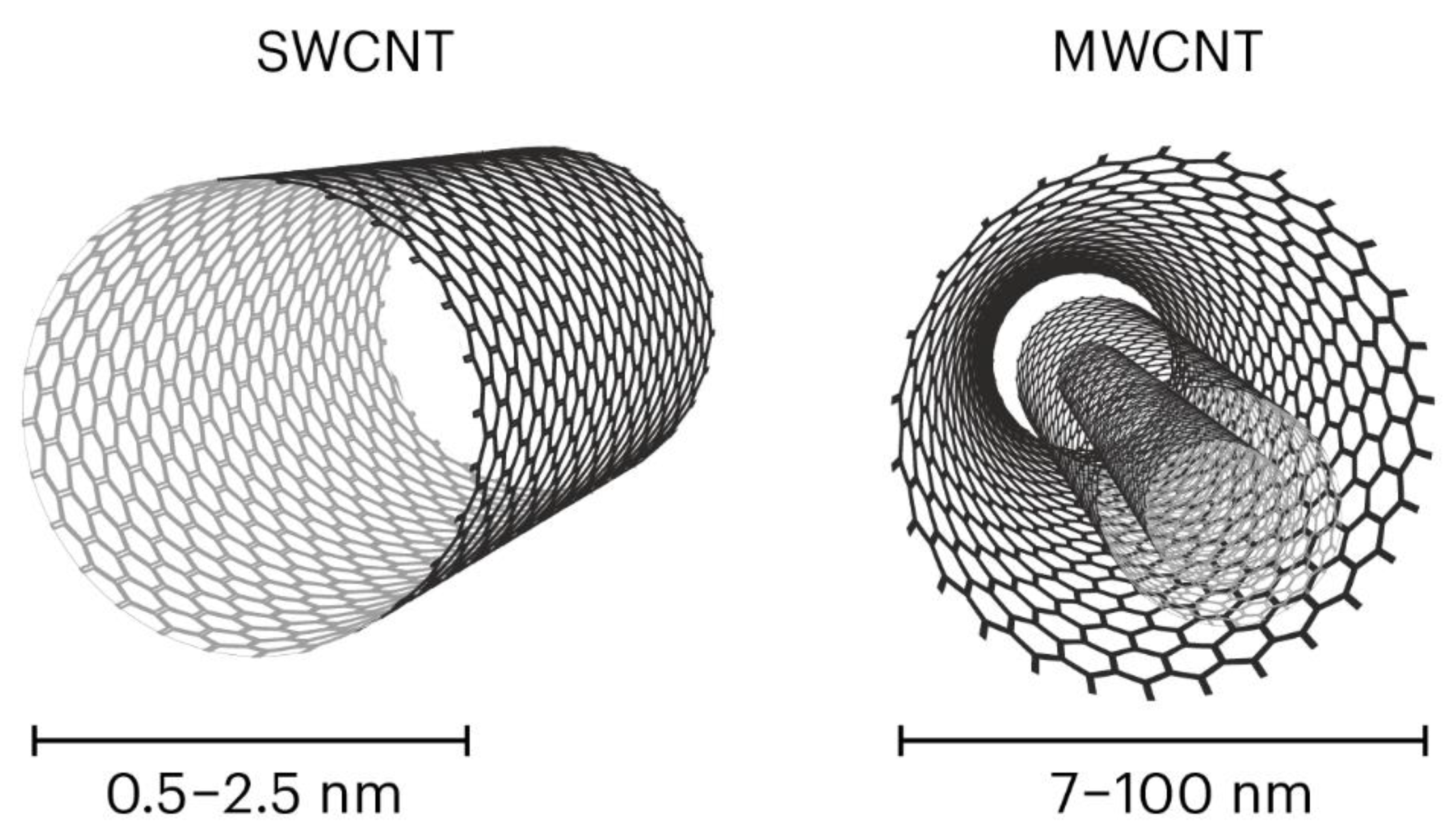
CNTs are classified into single-walled carbon nanotubes (SWCNTs) and multi-walled carbon nanotubes (MWCNTs) based on the number of layers present in the structure (
Figure 3). SWCNTs consist of single-layer of graphene whereas MWCNTs comprise a multilayer of graphene sheets of different diameters.
Most applications deal with multiwall carbon nanotubes (MWCNTs), which can be thought of as a number of tubes nested inside each other, similar to the rings of a tree or a folded telescopic antenna, as shown in
Figure 3. The production technology of MWCNT is relatively unsophisticated and has been successfully developed by over 120 companies around the world [
57].
The synthesis technology of nanotubes with single-layer thick wall, or single-wall carbon nanotubes (SWCNTs), is more complicated. So far, only one manufacturer of SWCNTs has succeeded in large-scale production.
MWCNTs are long tubes, but the length is not crucial in many applications. The aspect ratio, i.e., the length-to-diameter ratio, is often more important. For MWCNTs with typical diameters between 7 and 100 nm, the aspect ratio is typically between 50 and 4,000. With just single-layer walls, SWCNTs are even thinner (0.5 to 2.5 nm) and because of that, their aspect ratio is typically greater and often goes up to 10,000.
MWCNTs also have high thermal conductivity and can be used in normally insulative materials to increase their ability to transmit heat. This can be useful in applications where heat needs to be dissipated, such as in electronics. In cases where metals are prohibited due to unwanted stresses or chemical instability, thermally conductive ceramics can be advantageous. Again, SWCNTs can achieve a similar effect to traditional conductive additives but at lower dosages, minimising the possible negative impact on other properties of materials.
As for carbon nanotubes, which are the other investigated nanoparticles, the thermo-physical properties for a single phase are estimated according to the empirical correlations shown in Eq. 7, where Brinkman [
51] defined the dynamic viscosity of nanofluid (
) in terms of base-fluid (
The density, specific heat capacity, and rate of thermal conductivities of the nanofluids [
50,
53] are expressed as:
Here, the model by Xue [
54] considered to calculate the thermal conductivities is based on Eq 12.
where
shows the density of carbon nanotube,
denotes the specific heat of the carbon nanotube, and
,
represent the density and specific heat of base fluid, respectively.
Table 4 shows the values of the thermo-physical properties of the base fluid and CNTs in the two variants of SWCNTs and MWCNTs.
Table 5 shows the thermal conductivity values in the nanofluid for different percentages of dispersion in oil for SWCNTs and MWCNTs.
4. Numerical Results
4.1. CFD Setup
TMS analysis of the investigated electric machine requires the resolution of a conjugated conductive–convective problem.
RANS (Reynolds Averaged Navier–Stokes) equations and turbulence models are applied to describe the fluid flow evolution using a coupled implicit approach, adopting the κ-ε two-equations model for the turbulence fluctuations. In fluid regions, in particular, the transport equations have the following dimensional form:
| Mass equation |
|
Eq. 13 |
| Momentum equation |
|
Eq. 14 |
| Energy equation |
|
Eq. 15 |
The above equations are discretised using a finite volume formulation and solved by the FLUENT
® COUPLED algorithm associated with a well-assessed Algebraic Multigrid model. In conjunction with this, 2nd order spatial numerical upwind schemes have been adopted to discretise the spatial domain. All grids were generated considering the requirements that RANS calculations need near the wall. In solid regions, the energy transport equation used by FLUENT has the following dimensional form:
where:
ρ: density [kg/m3]
h: sensible enthalpy, [kJ/kgK]
k: thermal conductivity [W/mK]
T: temperature
Sh: volumetric heat source.
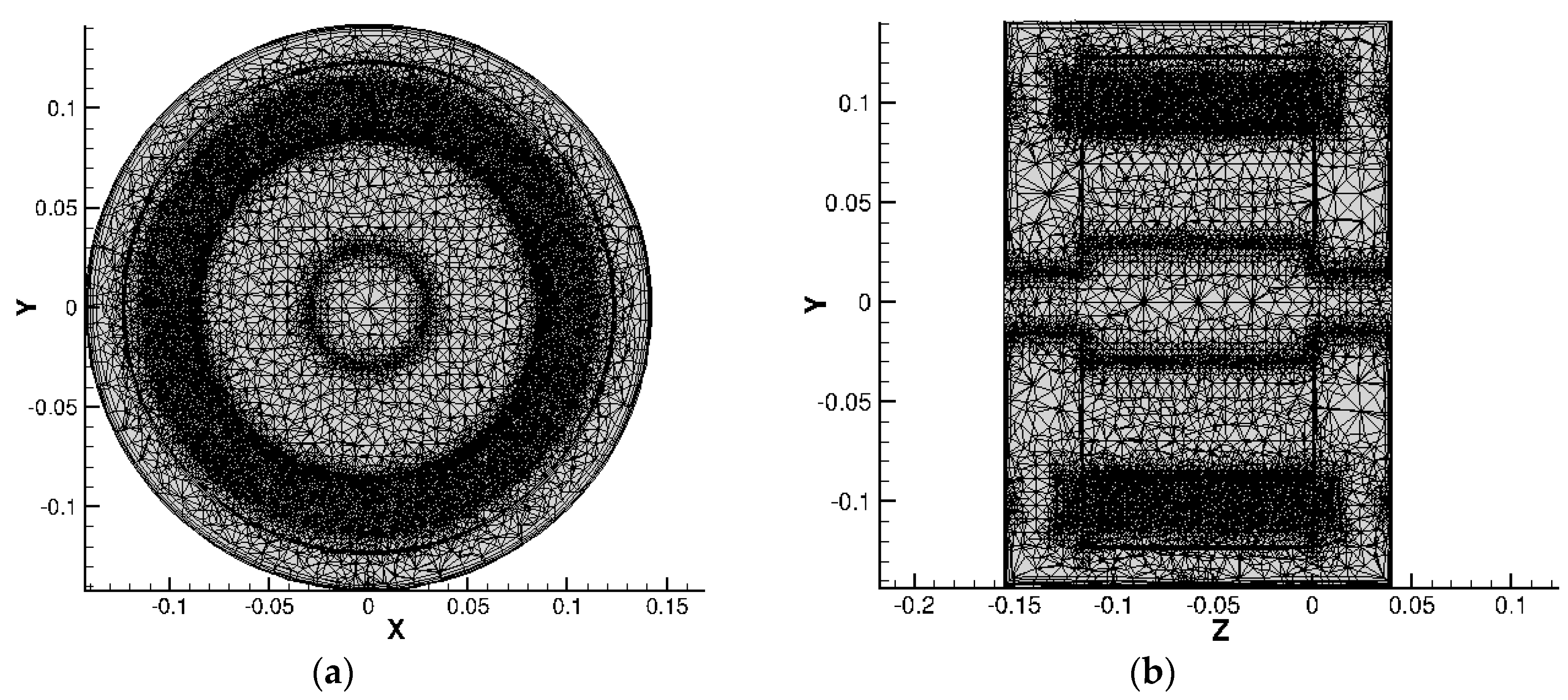
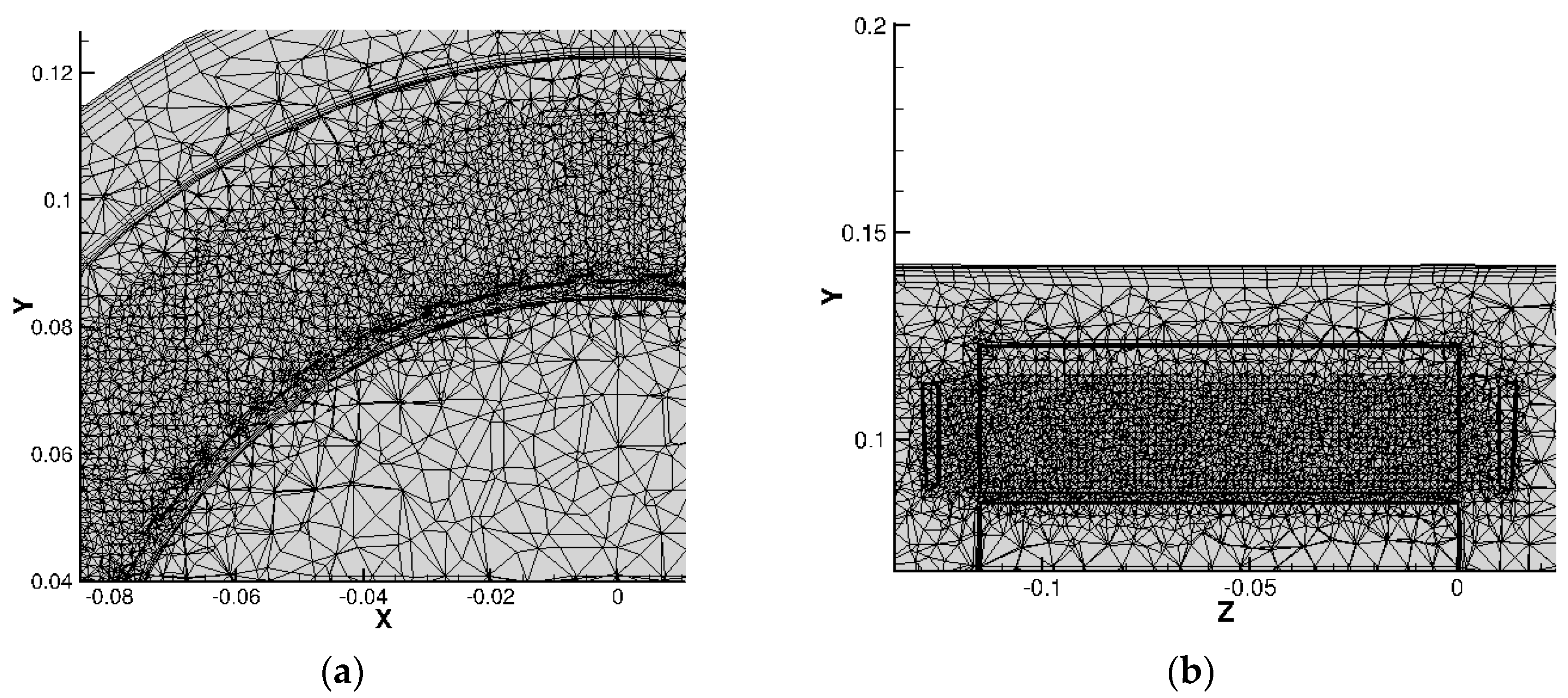
Regarding the grid generation, five prismatic layers were generated on each wall in the fluid domain. To improve the accuracy of the heat transfer calculation in the air gap, the mesh in the radial direction was built with ten layers, five on the rotor wall and five on the stator wall, and two or three layers of tetrahedrons. The solid domains, like windings and parts in ferromagnetic materials, were discretised using tetrahedrons, refining the mesh in the zones where a greater temperature gradient was forecast.
Figure 4a, b shows the views of the mesh at z = const. and at x = const., for which clustering is noticeable near the air gap and the end windings where higher temperature gradients are expected.
Figure 5 and
Figure 6 show close-ups of the stator, teeth, windings and end-winding.
Table 6 and
Table 7 summarise boundary conditions and mesh characteristics. A mesh independence study was conducted by creating three different levels of mesh refinement based on 8, 15, and 30 million cells, respectively. The main interest of the CFD (Computational Fluid Dynamics) analysis was to identify the maximum temperature reached in the solid zone. It was observed that the maximum temperature computed using the grid levels did not exceed 2%. The intermediate level was considered a good compromise for considering the computational effort and the accuracy of the results simultaneously.
4.2. Results Analysis
To evaluate the performance of the nanofluids, two numerical cases discussed in [
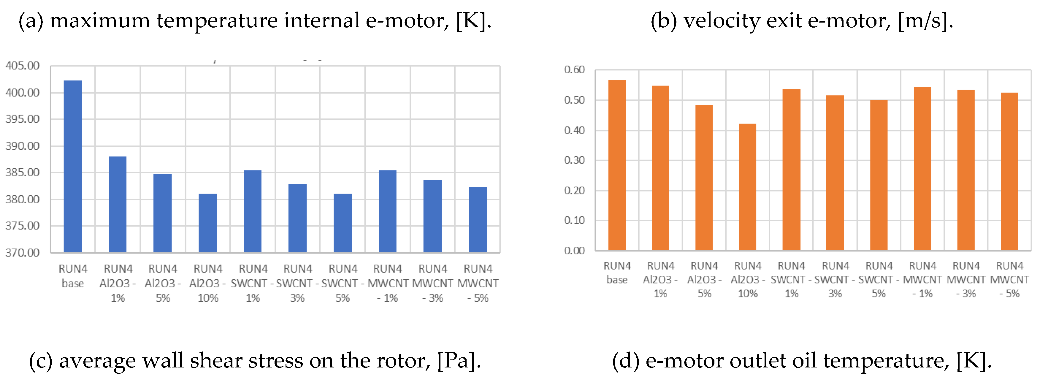
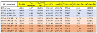
1] were selected: they relate to the same numerical setup with different oil mass flow rates (9-36 litres per hour), leading to the minimum and maximum values of 0.57 m/s and 4.49 m/s at the e-motor drain hole. These two cases are associated with identification labels starting with RUN4 or RUN10 (then the identification label is completed by the type of nanoparticle and the concentration). For each oil flow rate, alumina and nanotubes are added in different volume fractions. Therefore, apart from baseline solutions relative to pure diathermic oil, 18 simulations were carried out whose results are shown in following tables. In particular,
Table 8, related to RUN4, compares nanofluids in terms of maximum internal temperature, oil outlet velocity towards the radiator, pressure drop, and wall shear stress.
It can be noted that in the case of the fluid base, the highest temperature is about 400 K. With the dispersion of nanoparticles in the oil, this temperature is reduced up to 20 K less. This value is reached with ϕ = 5% of both SWCNT and MWCNT carbon nanotubes. Taking into account that a widely accepted rule of thumb for electric machines says that a 10-degree increase in operating temperature reduces the useful life by 50%; the 20 K temperature reduction will induce a longer life for the electrical motor considered in the study. Considering that the dispersion of nanoparticles in the oil increases the density and viscosity, an increase in the pumping power of the pump in the circuit shall be expected to reach the abovementioned goal. Since we are working with liquids (incompressible), the mechanical power can be considered almost negligible; therefore, the 20% increase does not concern the system's overall BoP (Balance of Plant). Conversely, reducing the maximum temperature of the materials by approximately 5% allows for a significant increase in their reliability, useful life and overstressing in off-nominal operating conditions.
Figure 7 shows the data summarized in
Table 8, for a more intuitive graphical comparison.
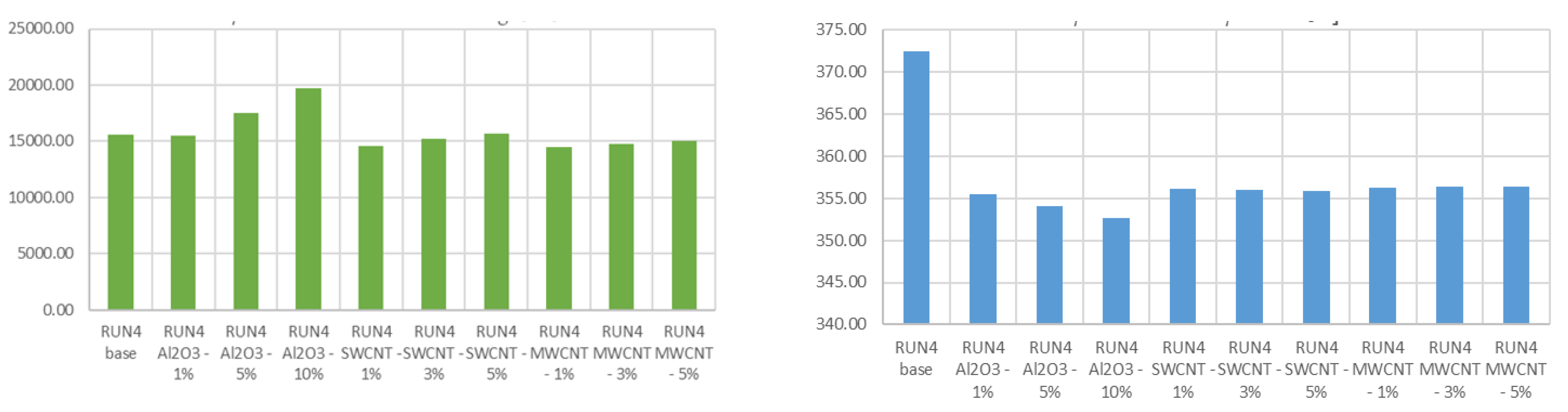
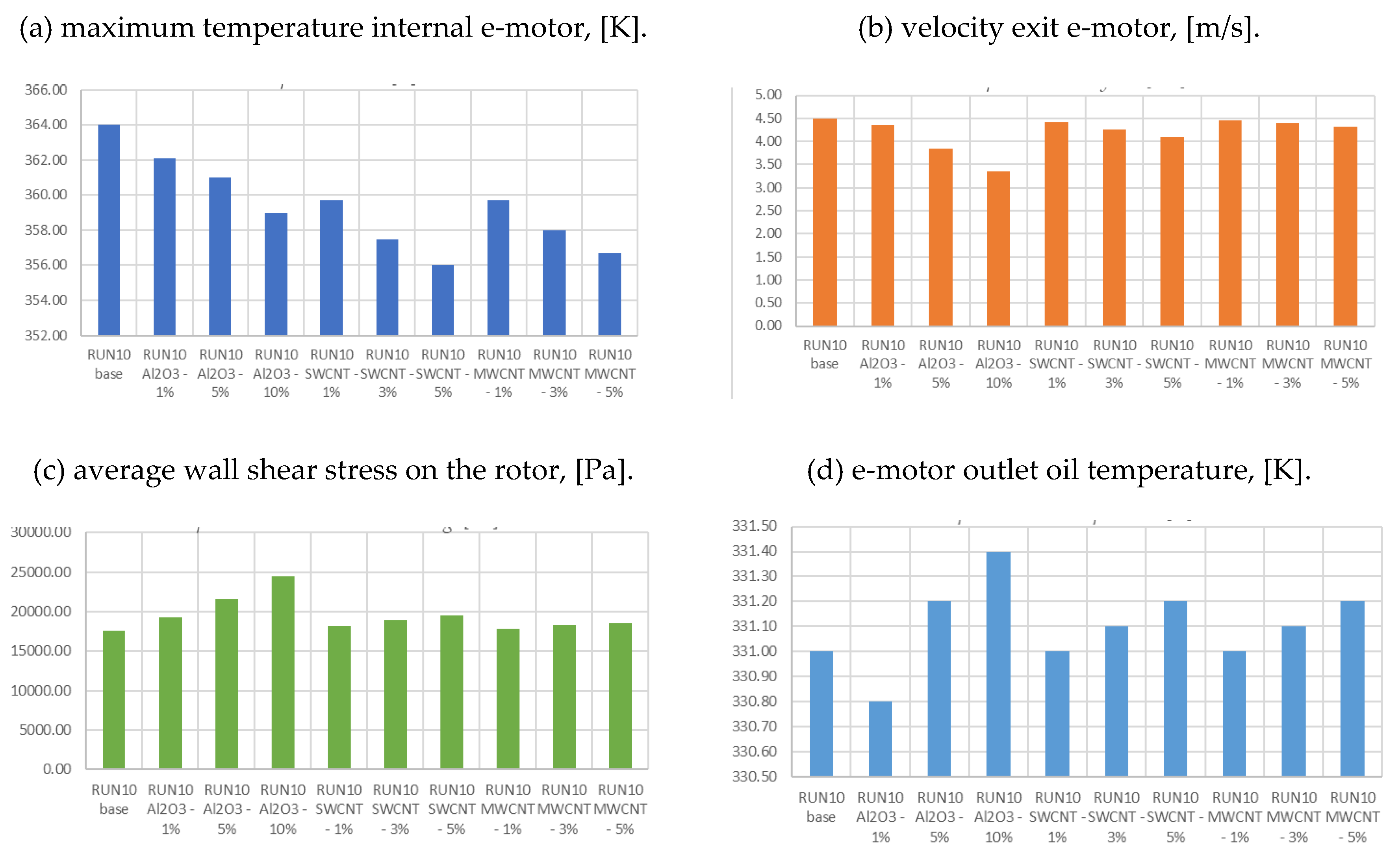
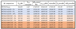
Table 9 below, compares nanofluids in terms of maximum internal temperature, oil outlet velocity towards the radiator, pressure drop, and wall shear stress for RUN10.
Figure 8 shows the data summarized in
Table 9, for a more intuitive graphical comparison.
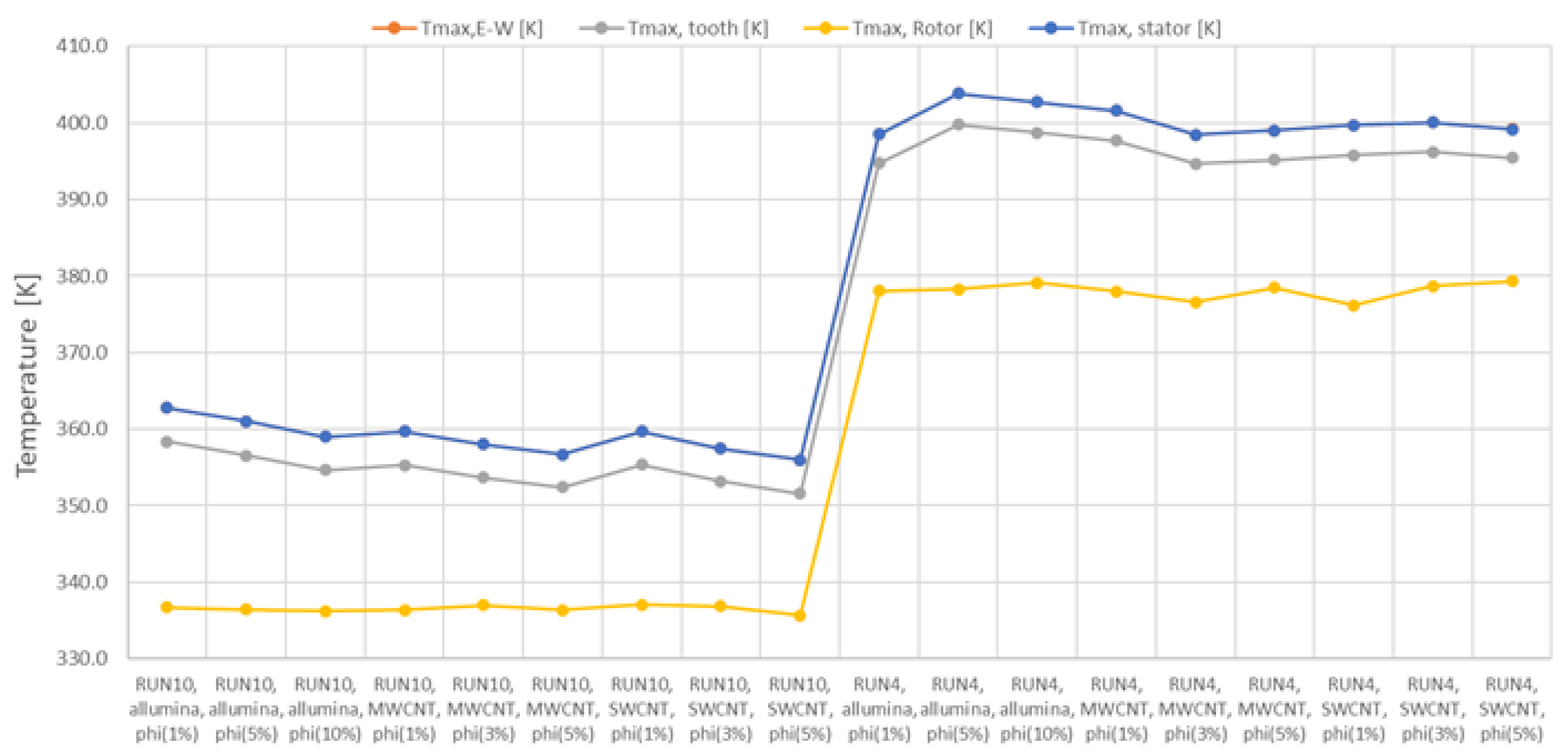
Figure 9 shows the temperature trend lines in function of the type of nanofluid used. The plotted temperature is the maximum temperature reached inside the motor (teeth), from which we can see that the case with the highest flow rate (RUN10) reaches lower temperatures on average than RUN4. At the same time, the relative influence of the nanofluids can be noted. In particular, they have a reductive effect on the maximum temperature of up to about 10%, but the most marked influence is noted as the flow rate of the cooling fluid increases.
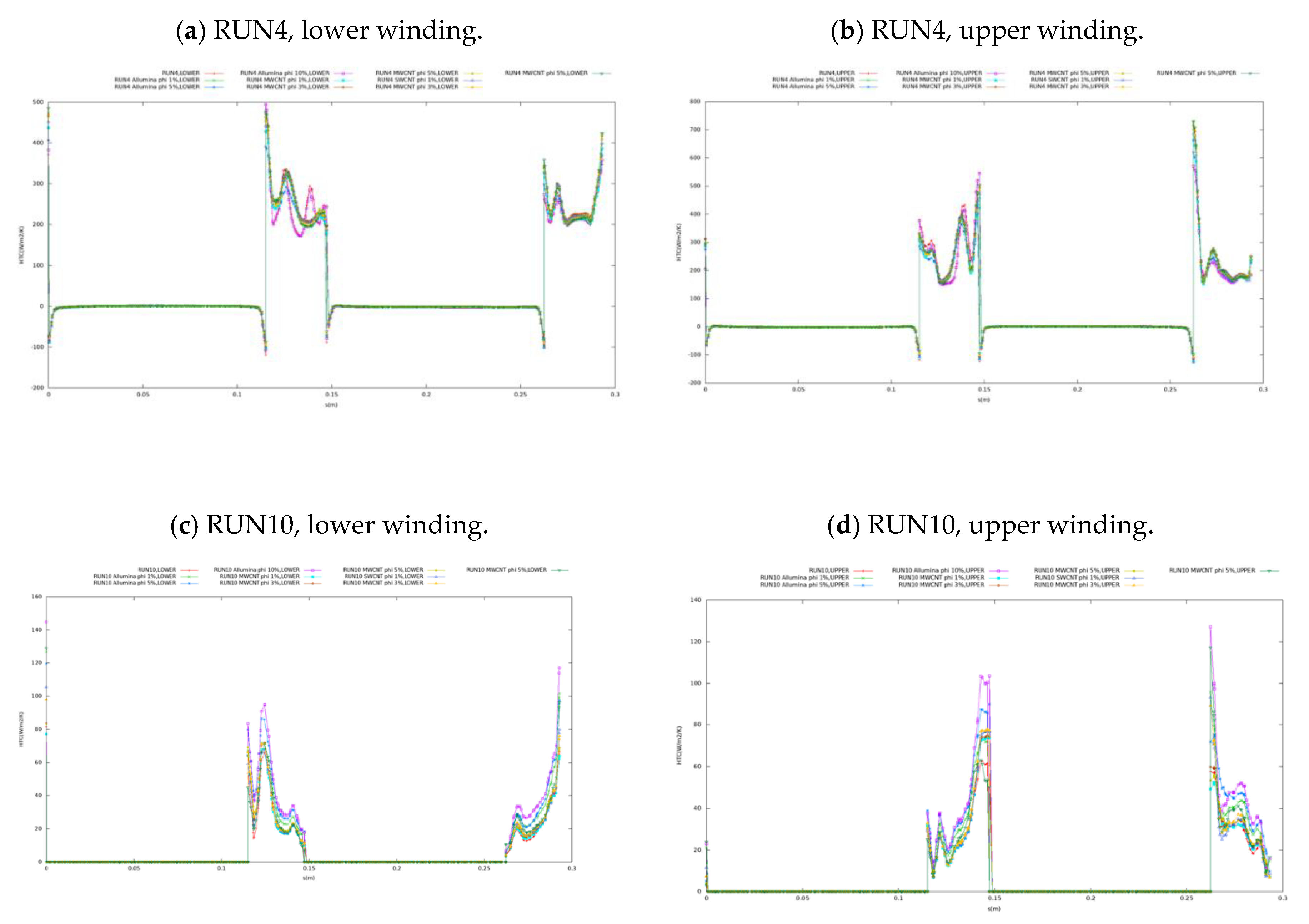
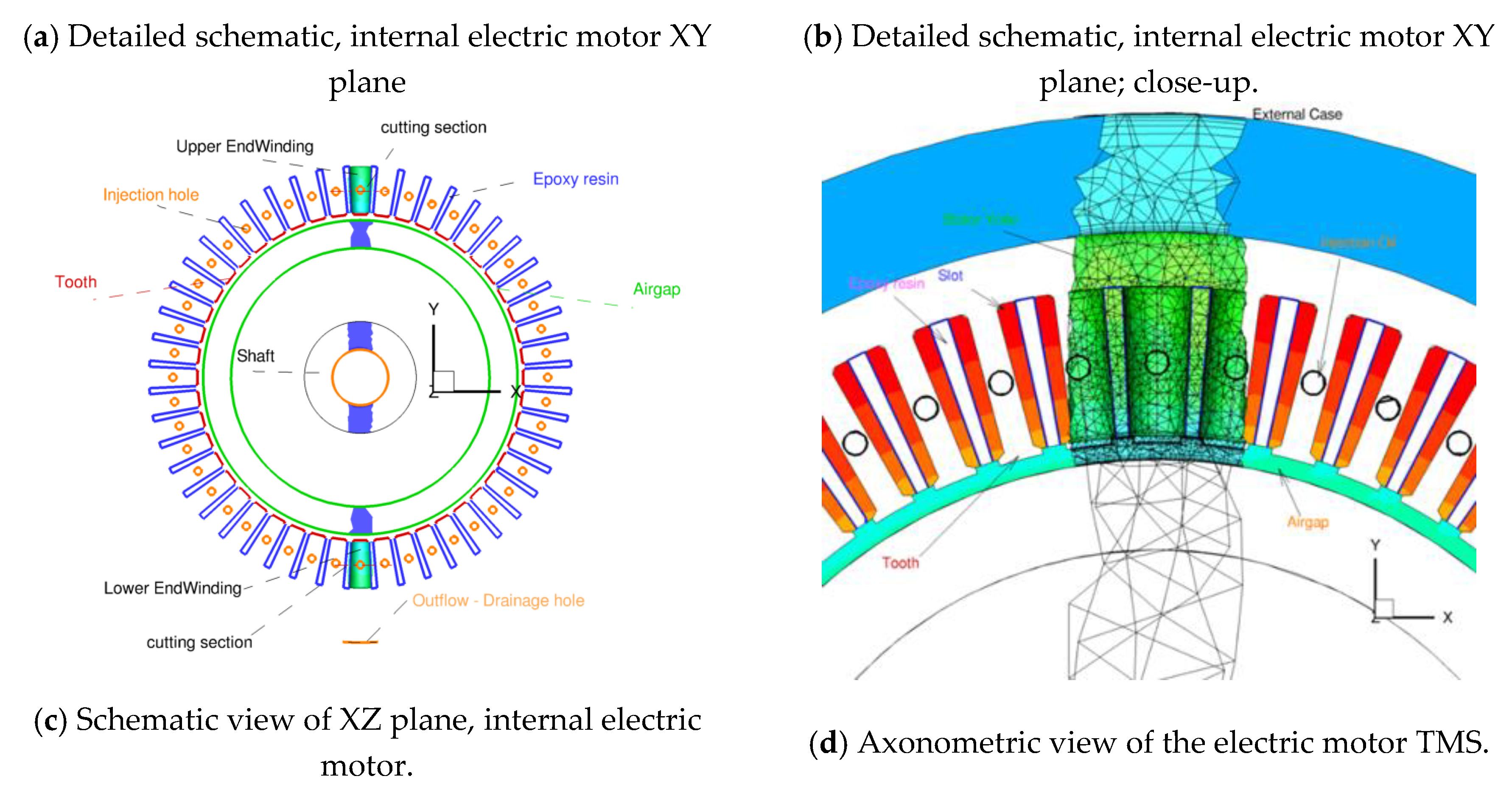
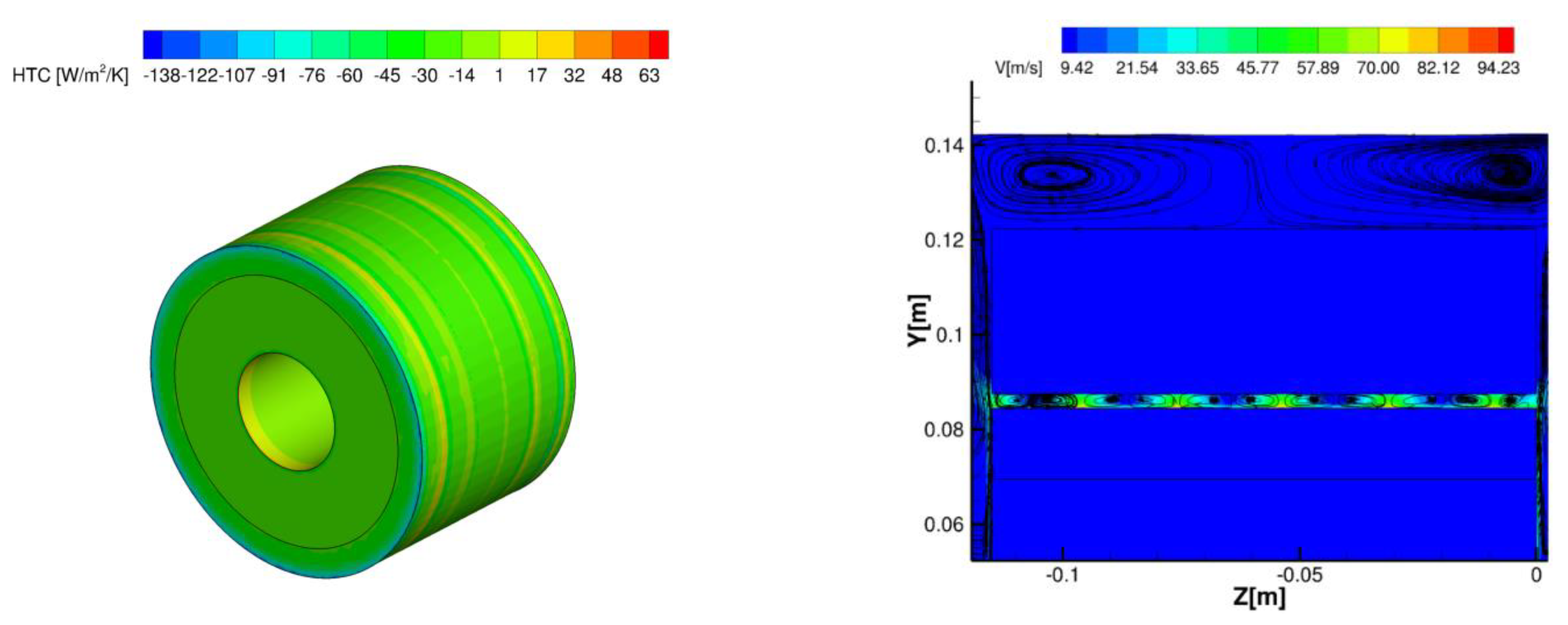
Figure 10 shows the trends of the convective heat exchange coefficient along two turns of the motor winding for RUN4 and RUN10. With reference to a single motor winding, two of them are considered for analysis, being distinguished as lower and upper windings depending on their position with respect to the drain hole (
Figure 11a). Lower and upper windings are named after the negative/positive y axis orientation (
Figure 11c). The Heat Transfer Coefficient (HTC) is evaluated with respect to the reference temperature of 325 K, which is the temperature of the oil inlet from the delivery holes. The curvilinear abscissa
s running along the entire winding is introduced to define to which point the analyses refer. A single winding consists of two turns (i.e., the end-windings) and two straight segments. The ranges 0.11 m <
s < 0.15 m and
s> 0.25 m represent the end-windings on the two sides of the motor. It can be noted that the areas where HTC is approximately 0 [W/m
2K] are those inside the stator cavity, which is filled with epoxy resin, therefore acting as an electrical insulator for the copper wires. It is also important to note that these trends are not symmetric because on the two sides of the motor (inside the housing, z=[z
min; z=z
max]) different vortices are established due to the lack of symmetry of the thermo-fluid dynamic system. This depends on the rotor surface where a rotation speed is imposed and the presence of the non-symmetric drain hole in the computational domain.
Figure 10 emphasizes that the highest HTC values can be found for the nanofluid MWCNT with the highest concentration. Concerning the alumina-based nanofluids, because of their higher density, they behave differently mainly due to the greater inertial forces and the more marked effect of gravity (buoyancy).
Finally,
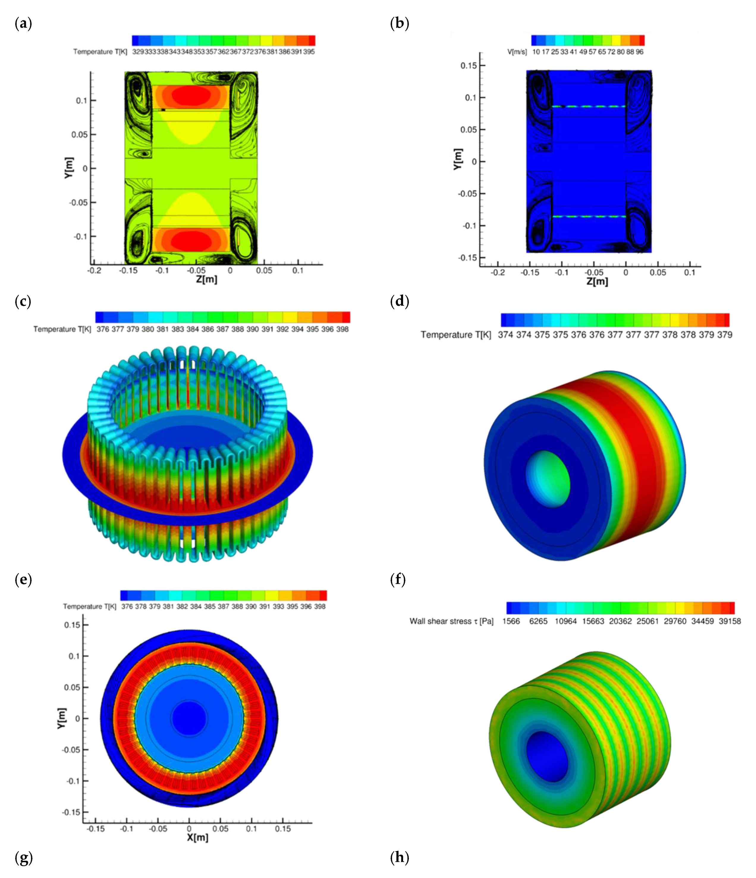
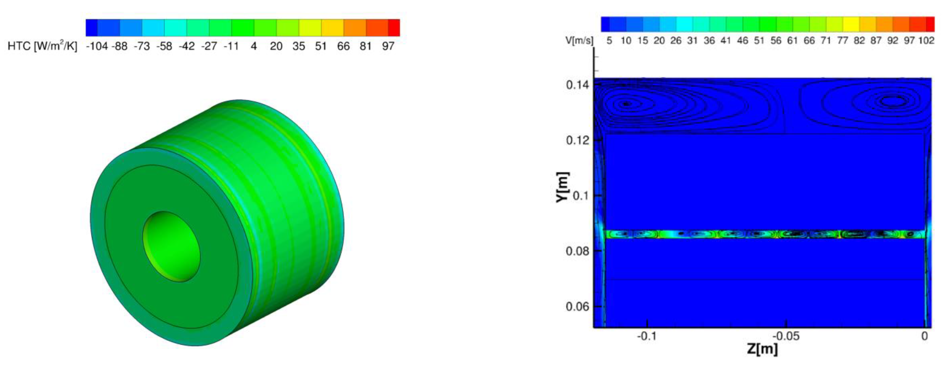
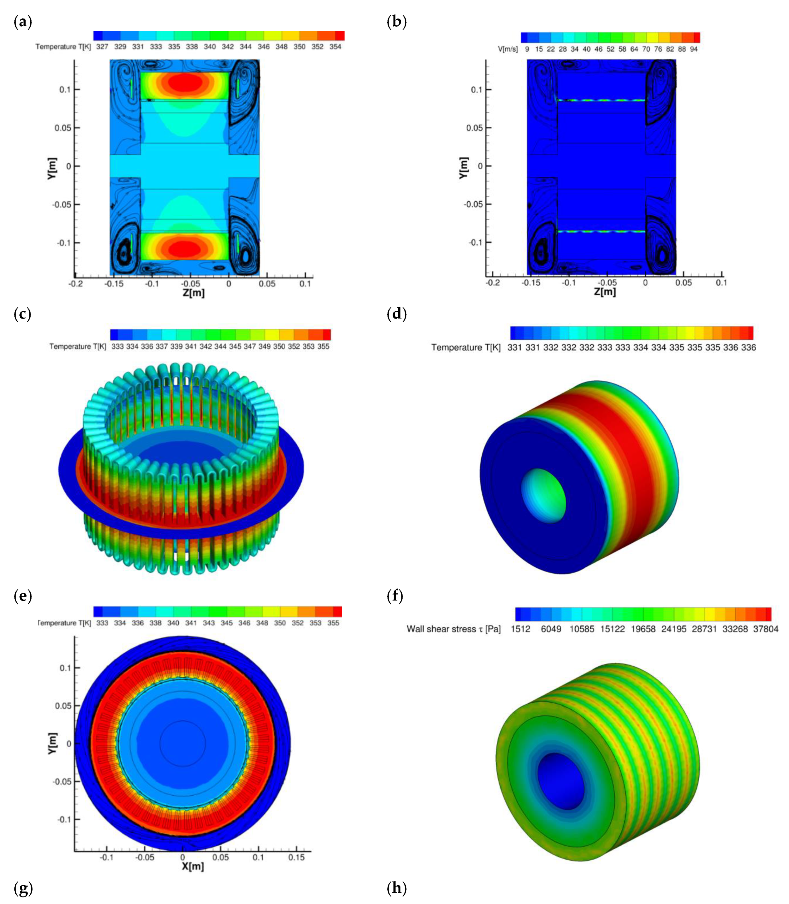
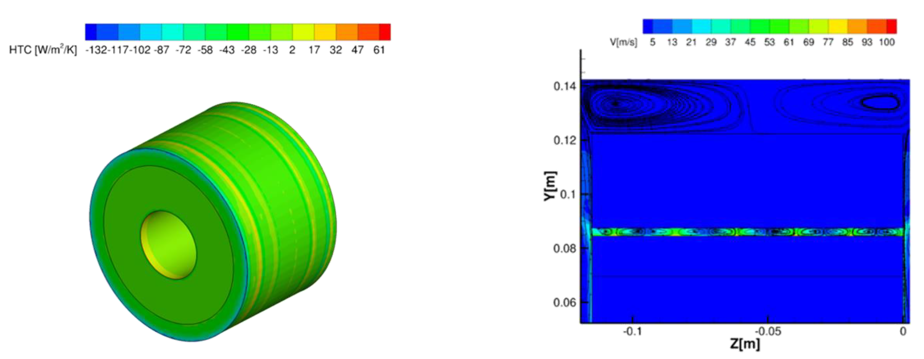
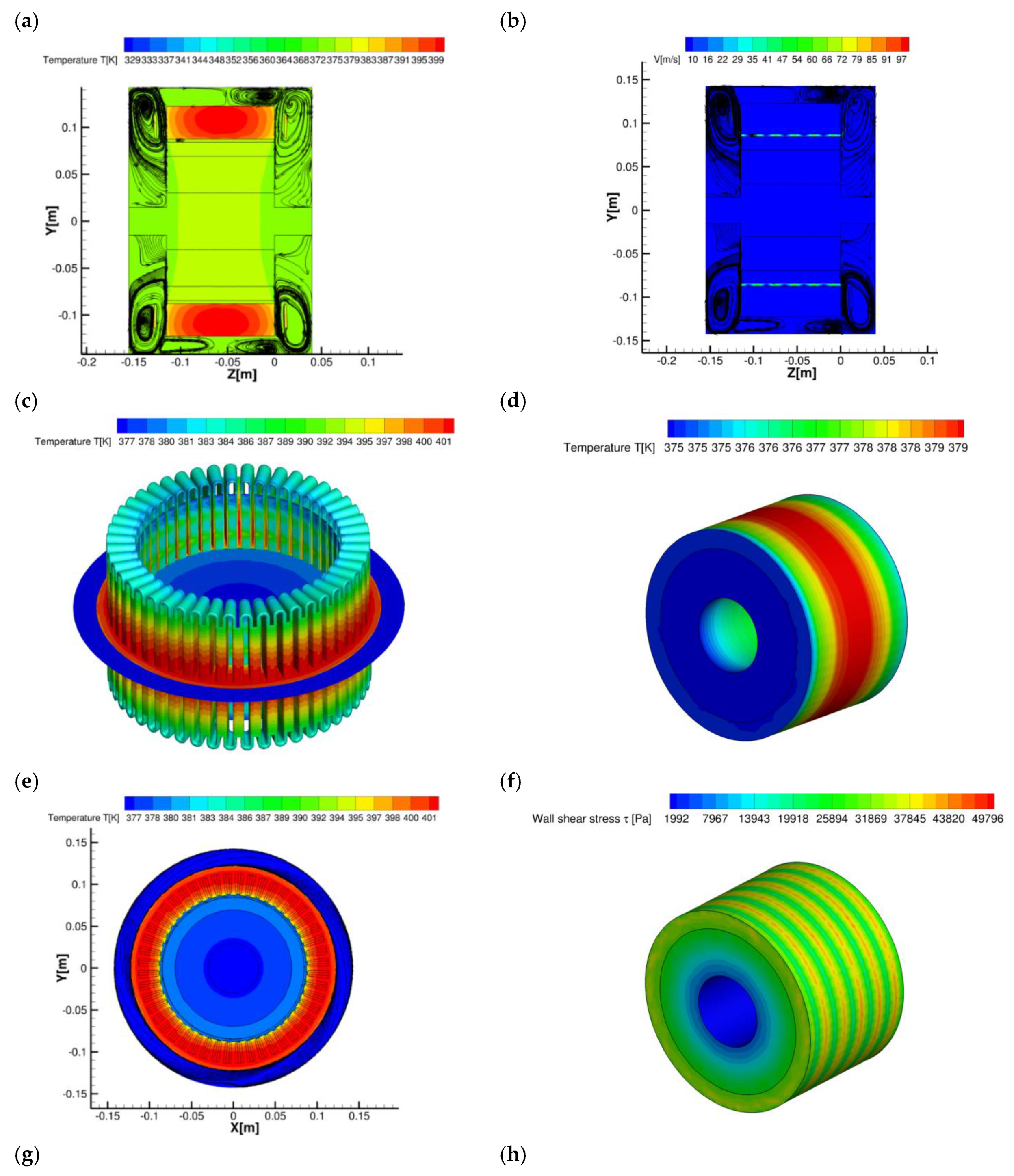
Figure 12,
Figure 13 and
Figure 14 display the most representative simulation results for the three considered types of nanofluids (Al
2O
3, SWCNT and MWCNT) when nanoparticles are taken at maximum concentration and the cooling fluid flow rate is the minimum. In particular, each figure assembles the following contour maps: (a) temperature and streamlines at plane x = 0 (symmetry plane); (b) velocity magnitude; (c) temperature on windings; (d) temperature on rotor; (e) temperature at plane z = 0 (transversal section); (f) WSS (Wall Shear Stress) on rotor; (g) HTC on rotor; (h) close-up of the velocity magnitude in the airgap at plane x = 0.
By looking at graphs (a) of
Figure 12,
Figure 13 and
Figure 14, it can be seen from the ZY sections that the stator is the hottest area, where there is the maximum thermal load due to the Joule effect. As regards the graphs (b), it is possible to note the trend of the Taylor vortices in the airgap [
55,
56]. In the axonometric views, it is observed that the maximum temperature is found in the area of the motor close to the central rotational axis as it is the one furthest from the oil jets. For cases with a higher cooling fluid flow rate (RUN10), the effect of the Taylor vortices is almost eliminated, since the effect of the flow becomes more important; therefore, a lower temperature and higher HTC are predicted. Taylor vortices also influence wall shear stress, and it is possible to note the stripy trend on the rotor, as in graphs (f).
5. Conclusions and Remarks
The design of a cooling system for an electric motor is as important as its structural and electromagnetic design. To this end, selecting the most appropriate coolant can be critical to maintaining the operating temperature within the allowable range to ensure long life.
This work has presented the outcome of CIRA investigations on nanofluids as coolants to improve the thermal management system of a high-power aircraft electric motor. The case study has exploited the TMS already designed by the CIRA team for the electrical architecture of a generator proposed by the University of Nottingham (UNOTT) as part of the ORCHESTRA project. The performance of the TMS, which uses diathermic oil as coolant, has been compared with the one obtained when small concentrations of nanoparticles are added to the same diathermic oil.
Numerical simulations were carried out using two types of nanoparticles, alumina and carbon nanotubes, the latter with two different configurations (single-wall and multi-walls), and performing a concentration trade-off study for two limiting cases of coolant flow rates. Generally, by increasing the concentration of these nanoparticles, an enhancement of the heat transfer on the motor end windings is obtained despite increased friction losses. The best results are achieved with a higher concentration of nanoparticles that improve the average thermal conductivity of the resulting fluid. For this type of application, carbon nanotubes are preferable to alumina, since they have higher thermal conductivity, fewer thickening problems, are lighter and hollow. Moreover, they do not interfere with electric and magnetic fields due to the higher dielectric strength of the carbon-based materials, thus they avoid unwanted circulation and/or discharges of current.
The maximum temperatures of the electric motor are approximately 10% lower than those achieved with diathermic oil alone. This result is significant as a safety margin is needed in all cases where a sudden increase in power occurs.
As a final observation, it can be added that the TMS with nanofluids replacing diathermic oil, while ensuring that the temperature remains below the allowable limit for maximum loads, does not resolve the cooling asymmetry in the central part (along the direction of the rotational axis) of the motor, where fluid circulation is difficult and cooling occurs mainly by conduction from nearby areas.
This challenge will be explored in depth in future works.
Author Contributions
Conceptualization, G.D.L, D.G.R., and A.C.; Data curation, G.D.L.; Formal analysis, G.D.L., D.G.R., A.P., and A.C.; Investigation, G.D.L and A.C.; Methodology, G.D.L. and A.C.; Project administration, A.P.; Software, A.C.; Supervision, A.P.; Validation, G.D.L., A.C., and D.G.R.; Writing—original draft, G.D.L., D.G.R., A.C., and A.P.; Writing—review & editing, G.D.L., D.G.R., and A.P.. All authors have read and agreed to the published version of the manuscript.
Funding
This research was funded by CIRA grant number 21-COM-0059 in the framework of PRO.R.A., the national (Italian) aerospace research programme, of which the ELECTROPLANE project is part.
Data Availability Statement
The authors declare that the data may be available upon request of the interested party.
Acknowledgments
The authors thank all the ELECTROPLANE team whose participants have provided (and continue to provide) valuable and constructive suggestions for the development of this research work.
Conflicts of Interest
The authors declare no conflicts of interest.
References
- Di Lorenzo, G.; Romano, D. G.; Carozza, A.; Pagano, A. Cooling of 1 MW Electric Motors through Submerged Oil Impinging Jets for Aeronautical Applications. Aerospace. 2024, 11, 585. [Google Scholar] [CrossRef]
- Mohammad, H. A.; Al-aswadi, A. A.; Shuaib, N. H.; Saidur, R. Convective heat transfer and fluid flow study over a step using nanofluids: A review. Renewable and Sustainable Energy Reviews. 2011, 15, 2545–3326. [Google Scholar] [CrossRef]
- da Cruz Schneid, A.; Albuquerque, L. J. C.; Mondo, G.B.; Colin, M.; Picco, A. S.; Cardoso, M. Colloidal stability and degradability of silica nanoparticles in biological fluids: a review. J Sol-Gel Sci Technol. 2022, 102, 41–62. [Google Scholar] [CrossRef]
- Yılmaz Aydın, D. , Gürü, M. Nanofluids: preparation, stability, properties, and thermal performance in terms of thermo-hydraulic, thermodynamics and thermo-economic analysis. J Therm Anal Calorim. 2022, 147, 7631–7664. [Google Scholar] [CrossRef]
- Mukherjee, S.; Mishra, P. Ch.; Parashar, S. K. S.; Chaudhuri, P. Role of temperature on thermal conductivity of nanofluids: a brief literature review. Heat Mass Transfer. 2016, 52, 2575–2585. [Google Scholar] [CrossRef]
- Ta, V. D.; Carter, R. M.; Esenturk, E.; Connaughton, C.; Wasley, T. J.; Li, J.; Kay, R. W.; Stringer, J.; Smith, P. J.; Shephard, J. D. Dynamically controlled deposition of colloidal nanoparticle suspension in evaporating drops using laser radiation. J Soft Matter. 2016, 12, 4530–4536. [Google Scholar] [CrossRef]
- Hubao, A; Cao, H. ; Hu, R.; Chen, Y.F.; Gui, C.; Yang, Z. Regulating droplet impact dynamics of nanoparticle suspension: Phenomena, mechanisms, and implications. Physics of Fluids. 2024, 36, 012002. [Google Scholar] [CrossRef]
- Escorcia-Díaz, D; García-Mora, S. ; Rendón-Castrillón, L. Ramírez-Carmona, M., Ed.; Ocampo-López, C. Advancements in Nanoparticle Deposition Techniques for Diverse Substrates: A Review. J Nanomaterials. 2023, 13, 2586.
- Topuz, A.; Engin, T.; Alper Özalp, A.; Erdoğan, B.; Mert, S.; Yeter, A. Experimental investigation of optimum thermal performance and pressure drop of water-based Al2O3, TiO2 and ZnO nanofluids flowing inside a circular microchannel. J Therm Anal Calorim. 2018, 131, 2843–2863. [Google Scholar] [CrossRef]
- Safaei M. R.; Ahmadi, G; Goodarzi, M. S.; Shadloo, M.S.; Goshayeshi, H. R.; Dahari, M. Heat Transfer and Pressure Drop in Fully Developed Turbulent Flows of Graphene Nanoplatelets–Silver/Water Nanofluids. 2016. 1. 20.
- Singh, S.; Ghosh, S. G. Pressure drop and heat transfer characteristics in 60° Chevron plate heat exchanger using Al2O3, GNP and MWCNT nanofluids. International Journal of Numerical Methods for Heat & Fluid Flow. 2022. 32. 2750-2777.
- Ali, A. R. I.; Salam, B. A review on nanofluid: preparation, stability, thermophysical properties, heat transfer characteristics and application. SN Appl. Sci. 2020, 2, 1636. [Google Scholar] [CrossRef]
- Ungar, E. K.; Erickson, L. R. (NASA – Johnson Space Center, Houston, TX, USA). Assessment of the Use of nanofluids in Spacecraft Active Thermal Control Systems. AIAA 2011, September 29.
- Narvaez, J. A.; Veydt, A. R.; Wilkens, R. J. Evaluation of Nanofluids as Potential Novel Coolant for Aircraft Applications: The Case of De-ionized Water-Based Alumina Nanofluids. J. Heat Transfer 2014, 136(5), 051702. [Google Scholar] [CrossRef]
- Sayyaadi, H.; Mehrabipour, R. Efficiency enhancement of a gas turbine cycle using an optimized tubular recuperative heat exchanger. Energy. 2012, 38, 362–375. [Google Scholar] [CrossRef]
- Siddique, M.; Khaled, A.-R.A.; Abdulhafiz, N.I.; Boukhary, A.Y. Recent Advances in Heat Transfer Enhancements: A Review Report. Int. J. Chem. Eng. 2010, 2010, 28. [Google Scholar] [CrossRef]
- Masuda, H.; Ebata, A.; Teramae, K. Alteration of Thermal Conductivity and Viscosity of Liquid by Dispersing Ultra-Fine Particles (Dispersion of Al2o3, Sio2 and Tio2 Ultra-Fine Particles); ScienceOpen Inc.: Boston, MA, USA; Berlin, Germany; Budapest, Hungary, 1993; 227–233.
- Choi, S.U.S.; Eastman, J.A. Enhancing thermal conductivity of fluids with nanoparticles. In Proceedings of the Conference 1995 International Mechanical Engineering Congress and Exhibition, San Francisco, CA, USA, 12–17 November 1995. Other Information: PBD: October 1995; Argonne National Lab.: Lemont, IL, USA, 1995. [Google Scholar]
- Ali, N.; Teixeira, J.A.; Addali, A. New pH Correlations for Stainless Steel 316L, Alumina. and Copper(I) Oxide Nanofluids Fabricated at Controlled Sonication Temperatures. J. Nano. Res. 2019, 58, 125–138. [Google Scholar]
- Asadi, A. A guideline towards easing the decision-making process in selecting an effective nanofluid as a heat transfer fluid. Energy Convers. Manag. 2018, 175, 1–10. [Google Scholar] [CrossRef]
- Choi, S. U. S. A new field of scientific research and innovative applications. Heat Transf. Eng. 2008, 29, 429–431. [Google Scholar] [CrossRef]
- Chapman, J. W.; Hasseeb, H., Schnulo S. (NASA – Glenn Research Center, Cleveland, OH, USA). Thermal Management System Design for Electrifi ed Aircraft Propulsion Concepts. NASA/TM-20205011477, March 2021.
- Alsouda, F.; Bennett, N. S.; Saha, S. C.; Salehi, F.; Islam, M. S. Vapor Compression Cycle: A State-of-the-Art Review on Cycle Improvements, Water and Other Natural Refrigerants. Clean Technol. 2023, 5(2), 584–608. [Google Scholar] [CrossRef]
- Swain, B.; Memon, S. A; Achari, A. M.; Mehta, V. A REVIEW ON ANALYSIS AND MODELLING OF IMPINGING JETS. Journal of Mechanical Engineering Research & Developments (JMERD) 2019, 42(4), 43–51. [Google Scholar]
- THERMOPEDIA. Available online: URL (accessed on 10 07 2024).
- Chen, Q.; Zhang, X.; Zhang, J. Effects of Reynolds and Prandtl Numbers on Heat Transfer Around a Circular Cylinder by the Simplified Thermal Lattice Boltzmann Model. Commun. Comput. Phys. 2015, 17, 937–959. [Google Scholar] [CrossRef]
- Rey, C.; Rosant, J.-M. Reynolds Number and Prandtl Number Influence on the Determination of Isotropic Velocity and Temperature Turbulent Length Scales. Comte-Bellot, G., Mathieu, J. (eds) Advances in Turbulence. Springer, Berlin, Heidelberg. 1987, 209-214.
- Shukla, A. K.; Dewan, A. Flow and thermal characteristics of jet impingement: comprehensive review. International Journal Of Heat And Technology. 2017, 35, 153–166. [Google Scholar] [CrossRef]
- Darwish, A. M.; El-Kersh, A.-F.; El-Sheikh, M. N.; El-Moghazy, I. M. A Review on Nanofluid Impingement Jet Heat Transfer. International Journal of Nanotechnology and Allied Sciences. 2017, 1, 1–15. [Google Scholar]
- Fitzgerald, J. A.; Garimella, S. V. A study of the flow field or a confined and submerged impinging jet. Int. J. Heat Mass Transfer. 1998, 41(8), 1025–1034. [Google Scholar] [CrossRef]
- Lupton, T.L.; Murray, D.B.; Robinson, A.J. The effect of varying confinement levels on the heat transfer to a miniature impinging air jet. Eurotherm. Eindhoven, Netherlands. 2008.
- QATS. Available online: URL (accessed on 09 07 2024).
- Frank, M.; Papanikoulaou, M.; Drikakis, D.; Salonitis, K. Heat transfer across a fractal surface. J. Chem. Phys. 2019, 151, 134705. [Google Scholar] [CrossRef]
- Frank, M.; Drikakis, D. Solid-like heat transfer in confined liquids. Microfluid. Nanofluidics 2017, 21, 148. [Google Scholar] [CrossRef] [PubMed]
- Papanikolaou, M.; Frank, M.; Drikakis, D. Nanoflow over a fractal structure. Phys. Fluids 2016, 28, 082001. [Google Scholar] [CrossRef]
- Liu, Y.C.; Wang, Q.; Li, Z.; Tao, W. Dynamics and density profile of water in nanotubes as one-dimensional fluid. Langmuir 2005, 21, 12025–12030. [Google Scholar] [CrossRef] [PubMed]
- McGaughey, A.J.H.; Kaviany, M. Thermal conductivity decomposition and analysis using molecular dynamics simulations Part II. Complex silica structures. Int. J. Heat Mass Transf. 2004, 47, 1799–1816. [Google Scholar] [CrossRef]
- Sun, G.X.; Bonaccurso, E.; Franz, V.; Butt, H.J. Confined liquid: Simultaneous observation of a molecularly layered structure and hydrodynamic slip. J. Chem. Phys. 2002, 117, 10311. [Google Scholar] [CrossRef]
- Tao, Q.; Zhong, F.; Deng, Y.; Wang, Y.; Su, C. A Review of Nanofluids as Coolants for Thermal Management Systems in Fuel Cell Vehicles. Nanomaterials. 2023, 13, 2861. [Google Scholar] [CrossRef] [PubMed]
- Okonkwo, E. C.; Wole-Osho, I.; Almanassra, I. W.; Abdullatif, Y. M.; Al-Ansari, T. An updated review of nanofluids in various heat transfer devices. Journal of Thermal Analysis and Calorimetry. 2021, 145, 2817–2872. [Google Scholar] [CrossRef]
- Fundamentals of nanofluids for thermal management systems. Available online: URL (accessed on 23-07-2024).
- Yılmaz Aydın, D.; Gürü, M. Nanofluids: preparation, stability, properties, and thermal performance in terms of thermo-hydraulic, thermodynamics and thermo-economic analysis. J Therm Anal Calorim. 2022, 147, 7631–7664. [Google Scholar] [CrossRef]
- Kaggwa, A.; Carson, J.K. Developments and future insights of using nanofluids for heat transfer enhancements in thermal systems: a review of recent literature. Int Nano Lett. 2019, 9, 277–288. [Google Scholar] [CrossRef]
- Di Lorenzo, G.; Manca, O.; Nardini, S.; Ricci, D. Laminar confined impinging slot jets with nanofluids on heated surfaces. In Proceedings of the 2011 17th International Workshop on Thermal Investigations of ICs and Systems (THERMINIC), Paris, France, 27–29 September 2011; Volume 6, pp. 1–6. [Google Scholar]
- Di Lorenzo, G.; Manca, O.; Nardini, S.; Ricci, D. Numerical study of laminar confined impinging slot jets with nanofluids. Adv. Mech. Eng. 2012, 4, 248795. [Google Scholar] [CrossRef]
- Manca, O.; Ricci, D.; Nardini, S.; Di Lorenzo, G. Thermal and fluid dynamic behaviors of confined laminar impinging slot jets with nanofluids. Int. Commun. Heat Mass Transf. 2016, 70, 15–26. [Google Scholar] [CrossRef]
- Choi, S. Enhancing thermal conductivity of fluids with nanoparticle. D.A. Siginer, H.P. Wang (Eds.), Dev. Appl. Non-Newtonian Flows, 2, FED, ASME, New York 1995, pp.99-105.
- Li, Q.; Xuan, Y.; Yu, F. Experimental investigation of submerged single jet impingement using Cu-water. Nanofluid Appl. Therm. Eng. 36, 2012, 426-433.
- Tsutsui, M.; Yokota, K.; Lun Hsu, W. ; Garoli, D; Daiguij, H. ; Kawai, T. Peltier cooling for thermal management in nanofluidic devices. Device 2024, 2, 100188. [Google Scholar]
- Aman, S.; Khan, I.; Ismail, Z.; Salleh, M.Z.; Alshomrani, A.S.; Alghamdi, M.S. Magnetic field effect on Poiseuille flow and heat transfer of carbon nanotubes along a vertical channel filled with Casson fluid Citation. AIP Adv. 2017, 7, 015036. [Google Scholar] [CrossRef]
- Brinkman, H.C. The viscosity of concentrated suspensions and solution. J. Chem. Phys. 1952, 20, 571–581. [Google Scholar] [CrossRef]
- Fernandez, J.G.; Etesse, G.; Comesaña, E.; Seoane, N.; Zhu, X.; Hirakawa, K.; Garcia-Loureiro, A.; Bescond, M. Optimization of thermionic cooling semiconductor heterostructures with deep learning techniques. In Proceedings of the 2023 International Conference on Simulation of Semiconductor Processes and Devices (SISPAD), Kobe, Japan, 27–29 September 2023; pp. 281–284. [Google Scholar] [CrossRef]
- Halelfadi, S.; Mare, T.; Estelle, P. Efficiency of carbon nanotubes water based nanofluids as coolants. Exp. Therm. Fluid Sci. 2014, 53, 104–110. [Google Scholar] [CrossRef]
- Xue, Q. Model for thermal conductivity of carbon nanotube-based composites. Phys. B Condens. Matter 2005, 368, 302–307. [Google Scholar] [CrossRef]
- aylor G. I. (1923), “Stability of a viscous liquid contained between two rotating cylinders”, Philosophical Transactions of the Royal Society of London. Series A, Containing Papers of a Mathematical or Physical Character 223289–343, Published:01 January 1923. [CrossRef]
- Fénot, Matthieu et al. (2011) “A review of heat transfer between concentric rotating cylinders with or without axial flow.” International Journal of Thermal Sciences 50 (2011): 1138-115.
- https://www.researchandmarkets.com/reports/5324906/the-global-market-for-multi-walled-carbon (accessed on 05 09 2024).
Figure 2.
TMS oil cooling design [
1].
Figure 2.
TMS oil cooling design [
1].
Figure 3.
Schematic representation of a single-walled carbon nanotube (SWCNT) and a multi-walled carbon nanotube (MWCNT).
Figure 3.
Schematic representation of a single-walled carbon nanotube (SWCNT) and a multi-walled carbon nanotube (MWCNT).
Figure 4.
Details of the mesh, in the case with the presence of resin between the windings and d = 2 mm; (a) section at z = cost; (b) section at x = cost.
Figure 4.
Details of the mesh, in the case with the presence of resin between the windings and d = 2 mm; (a) section at z = cost; (b) section at x = cost.
Figure 5.
Mesh details: (a) stator; (b) windings along z-axis.Figure 6. Mesh details: (a) teeth and air-gap; (b) end-windings.
Figure 5.
Mesh details: (a) stator; (b) windings along z-axis.Figure 6. Mesh details: (a) teeth and air-gap; (b) end-windings.
Figure 6.
Mesh details: (a) teeth and air-gap; (b) end-windings.
Figure 6.
Mesh details: (a) teeth and air-gap; (b) end-windings.
Figure 7.
RUN4 CFD analysis at a cooling fluid rate of 0.57 m/s (the first bar of each chart refers to base fluid).
Figure 7.
RUN4 CFD analysis at a cooling fluid rate of 0.57 m/s (the first bar of each chart refers to base fluid).
Figure 8.
RUN10 CFD analysis at a cooling fluid rate of 4.49 m/s (the first bar of each chart refers to base fluid).
Figure 8.
RUN10 CFD analysis at a cooling fluid rate of 4.49 m/s (the first bar of each chart refers to base fluid).
Figure 9.
Comparison of temperatures on key components of the e-motor for the investigated nanofluids.
Figure 9.
Comparison of temperatures on key components of the e-motor for the investigated nanofluids.
Figure 10.
HTC distribution on the motor windings for RUN4 and RUN 10.
Figure 10.
HTC distribution on the motor windings for RUN4 and RUN 10.
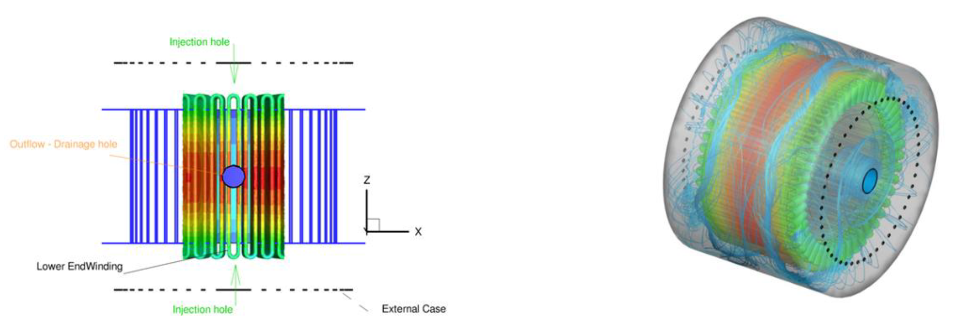
Figure 11.
Detailed views of the electric motor and TMS.
Figure 11.
Detailed views of the electric motor and TMS.
Figure 12.
Contour maps of the CFD domain of RUN4 SWCNT- 5%: (a) Temperature and streamlines x = const.; (b) velocity magnitude; (c) temperature on windings; (d) temperature on rotor; (e) temperature at section at z = const.; (f) WSS (Wall Shear Stress) on rotor; (g) HTC on rotor; (h) velocity magnitude in airgap zoomed section at x = const.
Figure 13.
Contour maps of the CFD domain of RUN4 MWCNT – 5%: (a) Temperature and streamlines x = const.; (b) velocity magnitude; (c) temperature on windings; (d) temperature on rotor; (e) temperature at section at z = const.; (f) WSS on rotor; (g) HTC on rotor; (h) velocity magnitude in airgap zoomed section at x = const.
Figure 14.
Contour maps of the CFD domain of RUN4 Al2O3 - 10%: (a) Temperature and stream-lines x = const.; (b) velocity magnitude; (c) temperature on windings; (d) temperature on rotor; (e) temperature at section at z = const.; (f) WSS on rotor; (g) HTC on rotor; (h) velocity magnitude in airgap zoomed section at x = const.
Table 1.
Thermo-physical properties of pure oil and Al2O3 particles at T=293 K.
Table 1.
Thermo-physical properties of pure oil and Al2O3 particles at T=293 K.
| Material |
ρ [kg/m3] |
cp [J/kg-K] |
µ [Pa*s] |
k [W/m-K] |
| Al2O3
|
3880 |
773 |
// |
36 |
| Diathermic Oil |
890 |
1950 |
0.0803 |
0.0106 |
| Water |
998.2 |
4182 |
993x10-6
|
0.597 |
Table 2.
Parameters Value Al2O3 – Oil.
Table 2.
Parameters Value Al2O3 – Oil.
| KB |
dp [nm] |
Tref [K] |
VB |
| 1.30x10⁻²³
|
30 |
293 |
0.457 |
Table 3.
Thermo-physical properties of Nanofluid at various volume fractions of Al2O3.
Table 3.
Thermo-physical properties of Nanofluid at various volume fractions of Al2O3.
| ϕ [%] |
ρ [kg/m3] |
cp [J/kg-K] |
µ [Pa·s] @ 20°C |
k [W/m-K] |
| 0 |
890 |
1.950E+03 |
8.032E-02 |
0.0106 |
| 1 |
919.9 |
1.938E+03 |
1.180E-01 |
0.0109 |
| 3 |
1010 |
1.903E+03 |
1.302E-01 |
0.0119 |
| 5 |
1040 |
1.891E+03 |
1.313E-01 |
0.0123 |
| 10 |
1189 |
1.832E+03 |
1.312E-01 |
0.0141 |
Table 4.
Thermo-physical properties of some base fluids and carbon nanotubes (CNTs). (1) Single-walled carbon nanotube; (2) multi-walled carbon nanotube.
Table 4.
Thermo-physical properties of some base fluids and carbon nanotubes (CNTs). (1) Single-walled carbon nanotube; (2) multi-walled carbon nanotube.
| Physical Properties |
Density ρ [kg/m3] |
Thermal Conduct k [W/m-K] |
Specific Heat cp [J/kg-K] |
| |
Water |
997 |
0.613 |
4197 |
| Base fluid |
Kerosene (lamp) oil |
783 |
0.145 |
2090 |
| Diathermic Oil/ Engine Oil |
890 |
0.144 |
1910 |
| Nanoparticles |
SWCNT(1)
|
2600 |
6600 |
425 |
| MWCNT(2)
|
1600 |
3000 |
796 |
Table 5.
Thermal conductivity values of CNTs with different volume fraction values.
Table 5.
Thermal conductivity values of CNTs with different volume fraction values.
|
Volume Fraction
|
Thermal Conductivity for SWCNT
|
Thermal Conductivity for MWCNT
|
| 0.00 |
0.145 |
0.145 |
| 0.01 |
0.174 |
0.172 |
| 0.02 |
0.204 |
0.200 |
| 0.03 |
0.235 |
0.228 |
| 0.05 |
0.266 |
0.257 |
Table 6.
Review Boundary condition CFD cases.
Table 6.
Review Boundary condition CFD cases.
| Boundary Conditions |
Zones |
| MASS FLOW INLET |
inlet holes |
| OUTFLOW |
exit hole |
| MOVING WALL |
external rotor surfaces |
| WALL/no Slip |
the remainder |
| Constant heat flux |
teeth |
| Uniform heat power source (W/m3) |
stator yoke, end-winding, copper |
Table 7.
Number of cells for various test cases.
Table 7.
Number of cells for various test cases.
| Id. |
Configuration Status 1 |
Configuration Status 2 |
Nr. Cells |
| Mesh1 |
d = 2 mm |
Without Epoxy Resin |
20M |
| Mesh 2 |
d = 2 mm |
With Epoxy Resin |
15M |
| Mesh 3 |
d = 4 mm |
Without Epoxy Resin |
20M |
| Mesh 4 |
d = 4 mm |
With Epoxy Resin |
15M |
Table 8.
Test matrix CFD simulation for Run4.
Table 8.
Test matrix CFD simulation for Run4.
Table 9.
Test matrix CFD simulation for RUN10.
Table 9.
Test matrix CFD simulation for RUN10.
|
Disclaimer/Publisher’s Note: The statements, opinions and data contained in all publications are solely those of the individual author(s) and contributor(s) and not of MDPI and/or the editor(s). MDPI and/or the editor(s) disclaim responsibility for any injury to people or property resulting from any ideas, methods, instructions or products referred to in the content. |
© 2024 by the authors. Licensee MDPI, Basel, Switzerland. This article is an open access article distributed under the terms and conditions of the Creative Commons Attribution (CC BY) license (http://creativecommons.org/licenses/by/4.0/).