
Submitted:
14 April 2025
Posted:
14 April 2025
You are already at the latest version
Abstract
Efficient water heating is essential for wool washing processes, which demand temperatures above 70°C. To meet this requirement sustainably, a parabolic trough solar concentrator system was proposed as an alternative to conventional natural gas systems. The design centers on a water pool constructed from bricks reinforced with an internal steel layer, enhancing heat exchange efficiency. Also, Various synthetic oils were analyzed as heat transfer fluids (HTFs) within an immersed heat exchanger, such as Thermia B oil, Heat transfer oil 32, Biphasic oil, and Therminol vp1 oil Nu-merical simulations have been done using ANSYS CFX software with the k-ε turbulence model, to evaluate the thermal performance and temperature distribution. Results demonstrate the superior efficiency of the solar-powered system, with the steel-reinforced pool achieving optimal water temperatures between 78°C and 85°C, exceeding the required threshold for industrial wool washing. Among various synthetic oils analyzed, Thermia B emerged as the most effective heat transfer fluid, maintaining water temperatures in the range of 75°C to 85°C. This superior thermal performance is attributed to its high thermal conductivity and reduced heat loss, ensuring con-sistent and optimal heat distribution for the wool washing process.
Keywords:
solar energy
; CSP
; wool washing
; ANSYS CFX
; heat transfer
1. Introduction
The textile industry, particularly in the transformation of wool, holds a pivotal role in light manufacturing processes. Wool undergoes several stages of processing to become a usable product, with the washing phase being among the most critical steps. This phase significantly influences the quality of the final wool product. Among the various methods employed for wool washing, the use of pools has emerged as one of the most widespread techniques. However, this method demands considerable amounts of water and energy, particularly for heating, which poses substantial challenges in terms of both resource consumption and environmental impact. The effluents generated during the process, despite being largely of natural origin, contribute significantly to potential pollution burdens in an industrial context. The heavy reliance on fossil fuels exacerbates these challenges, making the process highly energy-intensive and environmentally unsustainable. Consequently, European regulations strictly oversee wool-washing operations that exceed 500 kg/day to ensure compliance with sustainability and environmental standards [1].
Given these challenges, there is a growing emphasis on integrating sustainable practices and renewable energy solutions into wool processing. Various studies have contributed to this area, exploring innovative techniques and energy-efficient solutions. For instance, Sekine et al. conducted experiments on thermal stratification in water pools, providing insights into heat transfer mechanisms that are crucial for industrial applications [2]. Singh et al. extended this understanding by characterizing heat and mass transfer under low-pressure conditions, which have implications for efficient thermal management [3]. Mokhtar et al. demonstrated the application of solar energy systems for water heating, achieving remarkable thermal performance through the use of linear Fresnel receivers [4]. Famiglietti and Lecuona introduced an innovative solar thermal system designed to directly provide heat to industrial processes, eliminating the need for liquid heat transfer fluids and thereby simplifying installation and maintenance [5]. Additionally, Nunayon and Akanmu highlighted the feasibility of solar water heating systems for commercial purposes, showcasing their ability to achieve high water temperatures with minimal environmental impact [6]. Optimization studies, such as those conducted by Ma et al., utilized advanced algorithms to reduce energy consumption in water heating systems [7], while Li et al. successfully combined solar and geothermal heating technologies, significantly improving energy efficiency and reducing dependence on fossil fuels [8].
In the context of wool processing, there has been substantial research aimed at mitigating environmental impacts through the adoption of sustainable practices. For instance, Vade et al. examined the carbon emissions associated with wet wool processing and advocated for integrating renewable energy sources to minimize these emissions [9]. Popescu et al. reviewed enzymatic and non-traditional methods for wool cleaning, emphasizing techniques that reduce chemical usage while maintaining fiber quality [10]. Kherdekar et al. explored the use of natural cleaning agents in combination with ultrasound technology, demonstrating significant improvements in scouring efficiency, reduced water and chemical consumption, and enhanced fiber properties [11]. Similarly, Bozaci et al. investigated the application of plant-derived biosurfactants for eco-friendly wool cleaning, achieving reduced chemical oxygen demand (COD) in effluents without compromising wool quality [12]. The potential for energy-efficient wool processing has also been explored through the use of thermally optimized materials. Bansal et al. highlighted the thermal retention properties of bricks, suggesting their applicability in designing energy-efficient washing systems [13], while Anselmi et al. demonstrated that integrating enzymatic detergents and lowering water temperatures can reduce water consumption and pollution levels significantly [14].
Renewable energy has emerged as a transformative solution in wool processing, with studies showcasing its potential to reduce environmental footprints while enhancing operational efficiency. Farhana et al. reported that integrating solar thermal systems into washing processes could reduce energy consumption by up to 50%, aligning with circular economy principles such as water recycling and by-product recovery [15]. Danaci et al. highlighted the thermal insulation properties of wool-based materials, suggesting their application in designing systems that optimize energy use during wool washing [16]. These innovations underscore the importance of combining renewable energy with sustainable materials to enhance the efficiency and environmental performance of wool processing.
This research paper is part of a socio-economic project commissioned by a wool washing factory, aiming to address the factory's critical need for hot water at 70°C, which is essential for its operations. Currently, the factory relies on a conventional boiler to heat water, but the high cost of gas consumption prevents it from reaching the required temperature for a large water pool. The primary objective of this study is to explore the use of a small parabolic trough solar concentrator system, installed on factory rooftops, to generate industrial heat for wool processing. This system is designed to support key operations, including washing wool at approximately 70°C, by harnessing concentrated solar energy, the project seeks to meet the factory’s thermal needs while reducing its dependence on fossil fuels.
Additionally, a storage power system can be integrated using a dedicated tank, accompanied by an electric system to heat the heat transfer fluid. This system includes a circulation pump, valves for switching between charging and discharging modes, and a solenoid valve to optimize and regulate the circulation of the heat transfer fluid. Such a storage solution ensures continuous operation, even during the night or in adverse weather conditions, thereby guaranteeing stable and reliable performance.
The study emphasizes the potential of solar concentrators to improve energy efficiency, to contribute minimizing the environmental impacts, and promote sustainability in the wool processing industry. Traditional wool scouring processes, typically involving hot aqueous detergent solutions at 60–65°C, stand to benefit significantly from this approach, offering a sustainable solution without compromising operational effectiveness. By integrating renewable energy technologies, this research aims to set a benchmark for innovative and eco-friendly practices in the wool processing sector, ensuring reduced CO2 emissions and the preservation of fossil resources for future generations.
2. Materials and Methods
The materials and methods section provides a comprehensive description of the solar-powered system implemented for the wool washing process, detailing the structural components, operational principles, and thermal management strategies. The focus is on the integration of cylindrical-parabolic mirrors, absorber tubes, and a closed-loop heat transfer system designed to achieve optimal temperature control and energy efficiency, ensuring the sustainability of the process.
2.1. Structure of the Solar System for Wool Washing Process
The system consists of a solar field responsible for generating heat via cylindrical-parabolic mirrors and absorber tubes designed to capture maximum radiation [18,19]. A heat transfer fluid circulates through these tubes, heating up to approximately 146°C before being centralized and transported to the water pool. The solar field contains five cylindrical-parabolic modules, each designed with a length of 3 m and a width of 65 cm, and includes a mirror/receiver assembly that follows the Sun's movement for optimal energy capture. A variable-speed pump is used to control the maximum and minimum temperatures based on the water temperature required for wool washing. The heat transfer fluid, with a mass flow rate of 0.1 kg/s, heats the water in the pool to a temperature between 69°C and 85°C. The oil circulates in a closed loop, transferring the heat received from the solar field to the water pool and returning to the field at a temperature between 74°C and 88°C. A large water tank is used to fill the brick-constructed water pool, which includes a drainage valve to be emptied after each wool washing cycle. Figure 1 illustrates the operating principle of the system.
2.2. Heating System Design
To ensure a large quantity of wool washing per day in an industrial factory, the project is primarily linked to a socio-economic solution. The system is designed with a pool based on the practical requirements of the factory, with dimensions of 5 m in length, 1.4 m in width, and 0.8 m in height, resulting in a total volume of 5.6 m³. The heat transfer fluid tube, made of copper to ensure efficient heat exchange, has a serpentine shape with a diameter of 40 mm and a thickness of 2 mm. Figure 2 illustrates the design of the pool and the heat transfer fluid tubes
2.3. Thermodynamic Properties of Used Oils
To define the perfect heat fluid that reaches the goal, a list of fluids has been chosen and tested in the solar heating system proposed. These fluids are recommended in literature as:
a) Thermia B is designed to resist thermal decomposition when used within its recommended temperature range. Beyond this range, degradation, carbonization, or deposit formation may occur. The thermodynamic properties of Thermia B are provided by [17].
b) Heat Transfer Oil 32 has extended thermal stability for bulk oil temperatures of up to 300°C in closed heat transfer systems. However, when exposed to air in open systems, its operating temperature should not exceed 180°C. The thermodynamic properties of Heat Transfer oil 32 are provided by [18].
c) Therminol vp1 is a popular heat transfer fluid used in various industrial applications, particularly in high-temperature heat transfer systems. The thermodynamic properties of Therminol vp1 are provided by [19].
d) Biphasic oil (Syltherm 800) is a highly stable and durable silicone-based fluid designed for high-temperature operation in the liquid phase. It has a low fouling potential and can often remain in service for 10 years or more. The thermodynamic properties of Syltherm 800 are provided by [20].

Table 1.
Thermodynamic Properties of used oils at 100°C [17,18,19,20].
| Oils | Thermia B | Heat transfer oil 32 | Biphasic oil | Therminol vp1 | |
|---|---|---|---|---|---|
| Density (kg/m3) | 805 | 817 | 881.68 | 999 | |
| Specific heat capacity (kJ/kg.k) | 2.400 | 2.3 | 1.711 | 1.775 | |
| Thermal conductivity (W/m.k) | 0.129 | 0.11 | 0.1237 | 0.1277 | |
| Kinematic viscosity (mm2/s) | 5.1 | 5 | 3.86 | 0.986 | |
| Initial boiling point (°C) | 350 | 210 | 385 | 257 | |
3. Meshing and Mathematical Modeling
Firstly, to do the simulation, the parameter range for this study includes conditions imposed at the inlet, outlet, solid domain, and fluid domain, along with the interface between the fluid and solid regions. At the entrance of the computational domain, a mass flow rate of 0.1 kg/s, a solar flux of 0.8 kW/m² imposed by the cylindrical-parabolic collector opening on the receiver, a turbulence intensity of 5%, a turbulent viscosity ratio of 10%, and a water temperature equal to the ambient temperature of 25°C are specified. The temperature of the heat transfer fluid at the solar field outlet varies between 123°C and 146°C. At the outlet, ANSYS-CFX calculates the static pressure and imposes a zero-pressure gradient. The solid domain comprises a tube with a diameter of 40 mm and a thickness of 2 mm. The internal surface temperature of the pool is set to ambient temperature, with the heating surface of the absorber tube delivering a solar flux of 0.8 kW/m². The absorber tube is made of copper, while the pool is constructed with bricks featuring an inner steel layer. In the fluid domain, the heat transfer fluids considered include Thermia B, Heat Transfer Oil 32, Biphasic Oil (Syltherm 800), and Therminol VP1, while water is used as the pool fluid. At the interface between the fluid and solid regions, heat is transferred through conduction, where the heated fluid in the coil transmits thermal energy to the water in the pool. The efficiency of this heat exchange depends on the material conductivities and the flow conditions of the fluid.
By leveraging Computational Fluid Dynamics (CFD) tools, which are increasingly integral to the design and optimization of industrial applications due to their high accuracy and robustness, the study employs a second-order discretization method, commonly adopted in both commercial and open-source CFD software, as the dominant approach. Several mesh configurations, including mini elements and Taylor-Hood elements, were evaluated to balance computational efficiency and accuracy. In our case, the final adopted mesh configuration consists of 3,578,908 nodes (Figure 3), selected after comparing alternative configurations of 882,000 nodes, 1,172,000 nodes, and 2,488,604 nodes. The results of the value of temperature stable after this configuration even if increased to 3 868 964 nodes (Figure 4). This configuration optimizes the trade-off between accuracy and computational cost.
The problem is solved using CFD based on a mathematical model that integrates the conservation of mass, momentum, and energy, expressed in time-averaged tensor notation. Which is presented below:
- Continuity equation [21]:
• Momentum equation [21]:
• Energy equation [24]:
The change in flow direction after exiting the pipe generates turbulence in the oil flow, significantly impacting heat transfer. Therefore, turbulence modeling plays an important a crucial role. In this context, the k-ε turbulence model is used, with the standard wall function for near-wall analysis. The boundary layer problem is not resolved on the mesh. A detailed description of this model and its implementation in ANSYS CFX is provided by Launder and Spalding (1972) and ANSYS (2009) [22,23].
The turbulent kinetic energy (Kt) and the dissipation rate of turbulent kinetic energy (ε) are defined as follows:
- Turbulent kinetic energy (Kt) [21]:
- Turbulent kinetic energy dissipation (ε) [21]:
The mean Nusselt number is defined as [21]:
The Reynolds number is given by [21]:
- The volume V of a rectangular pool is given by:
L, W, and H are the pool's length, width, and height, respectively.
- The energy required to heat the water:
Where ΔT is the temperature increase, Cp is the specific heat capacity of water, and m is the mass of water is calculated as:
Where ρ is the density of water.
- Power supplied by solar concentrators:
The available thermal power depends on the total surface area of the concentrators:
Where N is the number of concentrators.
In which the unit area of concentrator module is:
I is the heat flux imposed.
η is the efficiency of system.
- Thermal power transferred to the oil:
It equals the effective power Peff, in another hand it calculated from:
where m is the mass flow rate of the oil, Cp is the specific heat capacity, and ΔToil is the temperature increase of the oil. Where the energy transferred to the water is calculated from:
t: presents the time.
4. Results and Discussion
The CFD results obtained by the ANSYS CFX simulation generally show that the parabolic trough solar micro-plant outperforms natural gas systems. Also, the use of synthetic oils had an effective effect on the temperature values and distribution. The new design washing pool in which a steel layer reinforces the pool provides the best thermal conductivity. These output data can be summarized in:
4.1. The Effect of Water Pool Design on Temperature
In Figure 5(a), the water temperature in the pool with an internal steel layer appears slightly more uniform, with smaller variations. In which, the water temperature varied approximately from 78.57°C to 84.84°C. Also, the brick pool without the steel layer shows a slightly different distribution, it varied from 78.80°C to 85.10°C as shown in Figure 5(b), with more clear distributions, especially in the central and lower regions. Where the heat is distributed more evenly in the steel-reinforced pool for higher thermal conductivity of steel than brick. This likely explains why temperatures are more consistent in the steel-lined pool. In which it seems to offer better thermal distribution, with more uniform temperatures and more efficient heat distribution. But, the brick with its lower thermal conductivity, exhibits greater temperature gradients, which means the heat diffuses less efficiently, creating areas with either higher or lower temperatures. This may indicate that while brick insulates better, it does not distribute heat as effectively as steel. This could lead to more pronounced temperature differences in the water over time. In summary, uses of steel appear to outperform brick in terms of thermal conductivity and uniform heat distribution, while brick, despite being more insulating, may cause localized heat accumulation.
4.2. The Temperature of Different Oils Inside Copper Tubes
The numerical simulation results shown in Figure (6) present heat transfer variation inside copper tubes. It demonstrates significant differences between the oils used. These variations are primarily due to the physical and thermodynamic properties of each oil, such as viscosity, heat capacity, and thermal conductivity. These parameters strongly influence the velocity of oil particles and their ability to transfer heat effectively to the surrounding medium. Where:
a) Heat transfer oil 32: reaches a maximum temperature of 146.9°C in specific regions of the tubes. However, most areas in the tubes exhibit temperatures around 123°C, as evidenced by the prevalence of green zones in Figure 7. This uneven heat distribution can be attributed to the oil's relatively high viscosity, which slows particle velocity and limits uniform heat diffusion within the tube. Despite achieving a higher maximum temperature than other oils, the overall heat transfer efficiency of Heat transfer oil 32 appears reduced, as only a small portion of the tube reaches this elevated temperature. This may indicate inefficiency in transferring heat to the water in the water pool compared to oils with a more uniform temperature distribution (Figure 6a).
b) Biphasic oil: achieves a maximum temperature of 123.5°C, close to the average temperature observed in different regions of the tubes. This indicates moderate heat transfer with average efficiency for heating the water pool. The heat distribution is more uniform than in Heat transfer oil 32 but less consistent than in Thermia B. Biphasic oil may offer a compromise between thermal efficiency and temperature stability, but its performance remains inferior to oils like Thermia B in terms of achieving a homogeneous thermal distribution (Figure 6b).
c) Thermia B: has a maximum temperature of 128.3°C, slightly lower than Heat transfer oil 32. However, the distribution of temperature within the tubes is much more uniform, with extensive red zones indicating high temperatures over a larger portion of the tubes. This homogeneity suggests a better capacity for consistently transferring heat to the water pool, maximizing thermal efficiency. Thermia B's ability to maintain a uniform distribution of high temperatures makes it more suitable for applications requiring consistent efficiency in heating large volumes of water or fluids (Figure 6c).
d) Therminol vp1: reaches a maximum temperature of 131.7°C, observed only at isolated points in the tubes. The majority of the tubes remain in a lower temperature range, between 92°C and 100°C. This suggests a limited ability of the oil to maintain high temperatures over a significant portion of the tubes, reducing its effectiveness in heating the water pool. The lack of widespread high temperatures may be due to high viscosity or lower specific heat capacity, limiting the amount of heat the oil can transport and distribute. This makes it less effective for applications requiring uniform and efficient heat transfer (Figure 6d).
An uneven temperature distribution in the tubes, as seen with Heat transfer oil 32 and Therminol vp1, limits the overall thermal transfer efficiency. When certain areas of the tube remain at relatively low temperatures, heat transfer to the water is reduced, directly affecting the overall heating system performance. In contrast, an oil like Thermia B, with a broad distribution of high temperatures, ensures more consistent and efficient heat transfer.
From the Figure 7 that shows the evolution of oil temperature in a width direction. The results indicate that Thermia B is the most efficient oil for ensuring homogeneous and effective heat transfer in copper tubes because have a shortest range of variation in temperature values [24]. That means the uniformity distribution provided by this oil in terms of temperature and heat transfer ratio. This is what makes it therefore preferable for industrial applications requiring uniform heating, such as solar heating systems or thermal processes demanding consistent efficiency. Conversely, Heat Transfer Oil 32 and Therminol vp1, while capable of achieving high maximum temperatures, suffer from uneven heat distribution (Figure 8), which limits their effectiveness. Biphasic Oil offers a middle ground with average performance and may be suitable for less demanding applications in terms of thermal efficiency [25].
4.3. Influence of Synthetic Oil Type on Water Temperature
In the steel-reinforced pool, four synthetic oils are used in heat transfer Heat transfer oil 32, Biphasic oil, Thermia B, and Therminol vp1. It examined their effect on the water thermal distribution in the washing pool in which the oil tubes are immersed. The parameters measured such as the oil temperature, water temperature, and heat transfer efficiency. It also considered some factors such as the contact surface between the tubes and water, as well as fluid circulation. From the Figure 8, The results of each oil show that:
a) Heat transfer oil 32: showed intermediate performance, with water temperatures varying between 61°C and 76°C. While partially meeting the requirements, its efficiency is limited by its lower heat transfer capacity, likely due to higher viscosity, which impedes circulation and, consequently, heat transfer (Figure 9a).
b) Biphasic oil: also demonstrated good results, where the within-range water temperatures were between 64°C and 82°C. Its biphasic design helps maintain a stable temperature, avoiding thermal fluctuations that could impair the wool-washing process. This stabilizing characteristic is especially critical for applications requiring constant temperatures (Figure 9b).
c) Thermia B: stood out for its superior performance, achieving water temperatures up to 85°C, with a low value observed of temperature equals 78°C. This performance can be attributed to its chemical formulation, which optimizes thermal conduction, enabling efficient heat transfer from the tubes to the water pool (Figure 9c).
d) Therminol vp1: exhibited the weakest performance, with temperatures ranging between 54°C and 69°C. The limitations of this oil can be attributed to its low thermal conductivity and unsuitable viscosity, reducing its effectiveness as a heat transfer fluid in this study's context (Figure 9d).
The results of the distribution of temperature in the pool high direction the critical importance of selecting the appropriate heat transfer fluid for wool washing processes (Figure 10). Where this demonstrates again that Thermia B oil provides uniform and stable variation of water temperature in all points of the pool that depends on the ability to reach high temperatures and maintain the stable thermal performance of Thermia B oil, which qualifies it as the optimal choice. While the other oils performed satisfactorily, they fell short of Thermia B’s energy efficiency, underscoring the direct impact of heat transfer fluid selection on overall system thermal performance [26]. More clearly, that shown as water temperature evolution curves depends on changing the chosen synthetic oil in Figure 10 and Figure 11. A significant temperature difference is observed between the various tested heat transfer fluids. Thermia B stands out for its ability to maintain the highest water temperatures between 75°C to 85°C, indicating superior thermal performance, likely due to better conductivity and lower heat loss. Biphasic Oil and Heat Transfer Oil 32 follow intermediate trajectories with water temperatures ranging from 67°C to 77°C and 64°C to 74°C, respectively, suggesting moderate thermal performance suitable for industrial heating applications. In contrast, the use of Therminol vp1 shows the lowest water temperature range starts from 55°C to 66°C, which indicates lower thermal efficiency, but it may still be useful for applications requiring regulation at moderate temperatures.
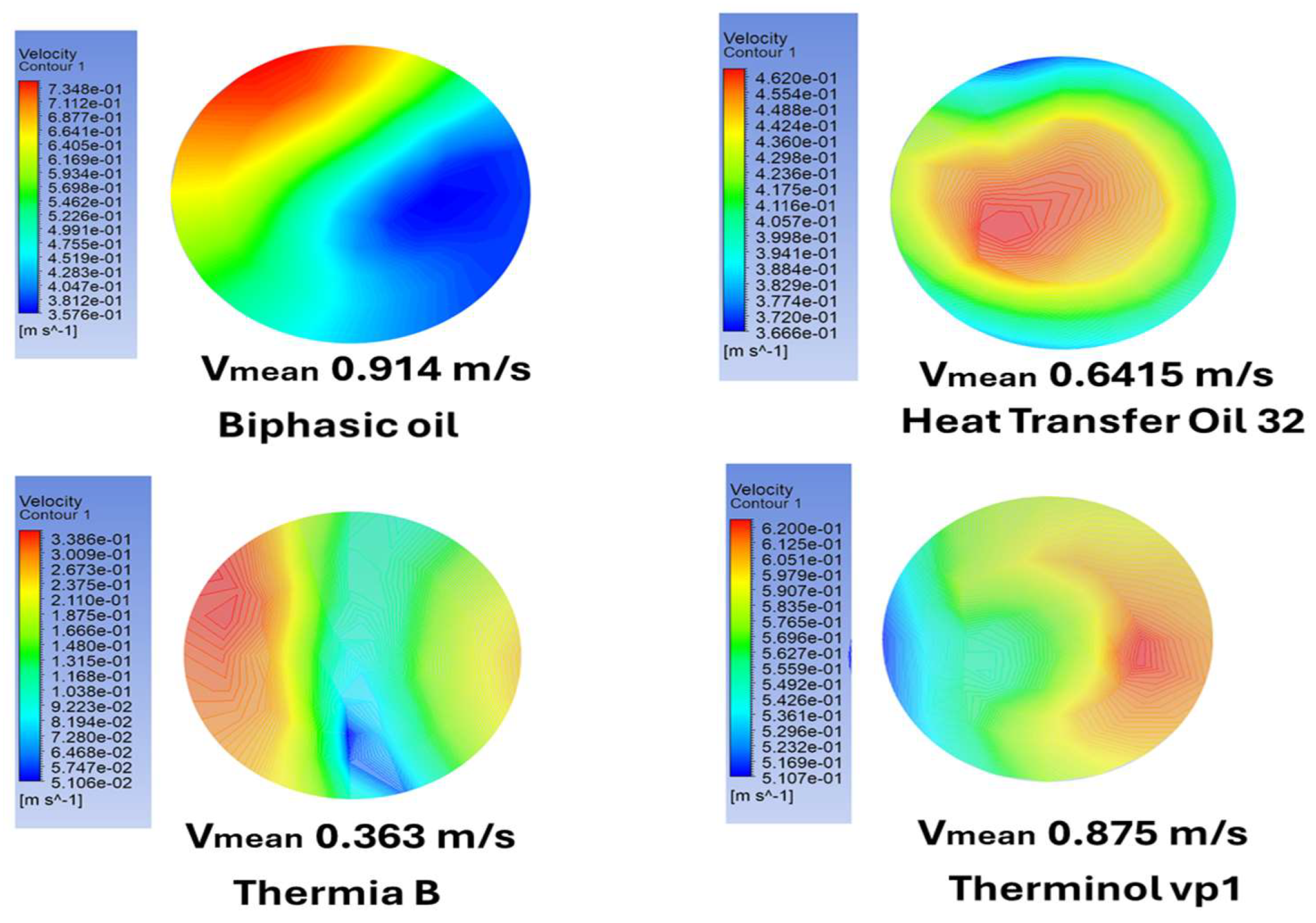
4.4. The Effect of Oil Velocity on Heat Exchange
The serpentine design of the tube, in which the heat transfer fluid circulates, forces the fluid to follow a longer and more complex path. This design aims to decrease pressure through the bends in the tube and changes in flow direction. These features reduce the oil's velocity and flow rate compared to a straight tube. The lower velocity of the oil within the tube allows for an extended residence time, facilitating better heat transfer to the water. Consequently, the prolonged contact time between the heat transfer fluid in the tube and water enhances the overall heat exchange efficiency.
In our case, the numerical results of velocity at the tube outlet, as shown in Figure 12, reveal variations based on the type of oil used. Among the tested oils, Thermia B exhibited the lowest outlet velocity, with a mean value of 0.363 m/s, followed by Heat Transfer Oil 32 (0.6415 m/s), Therminol vp1 Oil (0.875 m/s), and Biphasic Oil (0.914 m/s). This difference in velocity is primarily attributed to the viscosity of the oils. Thermia B demonstrated superior performance due to its lower velocity at the outlet, indicating that its viscosity was less affected by heat transfer processes. This characteristic allows its particles to spend more time transferring heat to the water. In contrast, the higher velocities observed for the other oils indicate a lower heat transfer efficiency compared to Thermia B.
5. Conclusions
This investigation delved into the integration of a parabolic through solar system to revolutionize water heating in the wool washing industry, an inherently energy-intensive process. Aimed at transitioning from conventional fossil fuel-dependent methods to renewable energy-driven systems, the study focused on enhancing thermal efficiency while addressing environmental sustainability challenges. The approach encompassed a holistic optimization of the system, emphasizing the design of the water pool and the selection of heat transfer fluids. Where it adopted a methodologically rigorous framework, utilizing a water pool constructed with a steel-reinforced interior to amplify thermal conductivity and ensure efficient heat distribution. The thermal performance of four synthetic oils Thermia B, Heat Transfer Oil 32, Biphasic Oil (Syltherm 800), and Therminol VP1was meticulously evaluated. Advanced computational fluid dynamics simulations, implemented through ANSYS CFX software and leveraging the k-ε turbulence model, provided nuanced insights into temperature profiles, heat transfer dynamics, and system efficacy. The results unequivocally identified Thermia B as the most effective heat transfer fluid, characterized by its capacity to maintain uniform and elevated temperature distributions. The steel-reinforced pool demonstrated superior thermal performance compared to a brick-only configuration, achieving optimal water temperatures between 78°C and 85°C, critical for industrial wool washing. The findings underscore the transformative potential of integrating renewable energy technologies in industrial processes, offering a dual benefit of operational efficiency and environmental stewardship. This study not only reinforces the viability of solar-powered systems but also lays a robust foundation for their broader application in energy-intensive industries, marking a significant stride toward a more sustainable industrial paradigm.
Author Contributions
Conceptualization, (H. M.), (D. M.) and (M. G-O); methodology, (H. M.); software, (H. M.), (D. M.)and (L.M.); validation, (G.L.), (A.B.) and (C.P.); formal analysis, (H. M.); investigation, (D. M.); resources, (M. G-O).; data curation, (D. M.); writing original draft preparation, (H. M.).; writing review and editing, (M. G-O) and (L.M.); visualization, (D. M.); supervision, (A.B.) and (L.M.); project administration (H. M.); funding acquisition, (G.L.) and (C.P.). All authors have read and agreed to the published version of the manuscript.
Funding
This work was supported by a grant of the Ministry of Research, Innovation and Digitalization, project number PNRR-C9-I8-760111/23.05.2023, code CF48/14.11.2022.
Institutional Review Board Statement
Not applicable.
Informed Consent Statement
Not applicable.
Data Availability Statement
Not applicable.
Conflicts of Interest
The authors declare no conflict of interest.
Nomenclature
| Instant fluctuation of velocity in x direction (m/s). | |
| Generation of turbulent kinetic energy due to the buoyancy force. | |
| Generation of the turbulent kinetic energy. | |
| Fluctuation of temperature (K). | |
| The mean temperature (K). | |
| and are coefficients | |
| Specific heat (J/kg.K). | |
| and | Turbulent Prandtl number. |
| Dissipation of the kinetic energy. | |
| D | Height (cm). |
| ɛt | Dissipation of the turbulent kinetic energy. |
| r | Diameter. |
| i and j | ith and jth elements. |
| kt | Turbulent kinetic energy. |
| L | Length (m). |
| T | Temperature of fluid (K) |
| u | Inlet velocity (m/s) |
| Gravity (m/s2) | |
| Kinetic energy. | |
| Pressure (Pa) | |
| Total. | |
| System coordinate (i= x, y, z- j=x, y, z). | |
| Viscosity (kg/m s) | |
| h | Convective Transfer coefficient |
| Q | The convective heat flux |
References
- Boileau, S., 1999. European regulations on wool washing processes. Environmental Compliance Reports, 12(1), pp.78-85.
- Sekine, M., Tanaka, K., & Yamada, S., 2018. Mechanisms of thermal stratification in industrial pools. Journal of Thermal Sciences, 45(1), pp.112-124.
- Singh, S., Patel, J., & Rao, N., 2020. Heat and mass transfer in static water pools under low pressure. Applied Thermal Engineering, 55(3), pp.215-225.
- Mokhtar, G., Touati, A., & Hammoudi, M., 2015. Thermal performance of solar water heating systems with linear Fresnel receivers. Solar Energy and Thermal Applications, 33(4), pp.223-234.
- Famiglietti, A. & Lecuona, A., 2019. Solar thermal systems for direct industrial heating. Solar Energy Technology, 56(5), pp.1123-1134.
- Nunayon, S.S. & Akanmu, W.P., 2020. Solar water heaters for commercial applications. Energy Efficiency in Commercial Systems, 24(3), pp.134-147.
- Ma, Y., Chen, L., & Zhao, H., 2021. Optimization of water heating systems using solar energy and air-source heat pumps. Journal of Renewable Energy Studies, 48(2), pp.145-157.
- Li, D., Zhang, X., & Wu, Y., 2022. Combined solar and geothermal heating for industrial applications. Renewable Energy Systems, 61(7), pp.234-247.
- Vade, A., Sharma, P., & Kiran, D., 2017. Carbon emissions in wool wet processing: Renewable energy solutions. Journal of Environmental Impact Studies, 29(2), pp.567-574.
- Popescu, C., Ivanov, I., & Toma, L., 2020. Environmentally sustainable methods for wool processing. Journal of Textile Innovations, 19(5), pp.567-579.
- Kherdekar, G., Patel, R., & Mehta, P., 2018. Ultrasound technology and natural agents in sustainable wool scouring. Advances in Textile Engineering, 14(8), pp.678-689.
- Bozaci, E., Yildiz, E., & Ozkan, K., 2016. Eco-friendly wool scouring using plant-derived biosurfactants. Green Chemistry in Textiles, 22(6), pp.567-574.
- Bansal, P., Kumar, S., & Sharma, R., 2017. Thermal retention properties of brick as a sustainable material for wool washing. Journal of Sustainable Materials Science, 45(4), pp.456-468.
- Anselmi, S., 2015. Traditional wool washing practices and eco-friendly alternatives. Textile Science Journal, 34(2), pp.123-135.
- Farhana, T., Ahmed, Z., & Hossain, M., 2022. Renewable energy integration in wool washing processes. Journal of Circular Economy Research, 15(1), pp.89-103.
- Danaci, H., Erdem, A., & Kaya, Y., 2016. Thermal performance of wool-based insulation materials in industrial applications. Thermal Science Journal, 39(3), pp.342-354.
- Shell, 2014. Technical Data Sheet: Shell Heat Transfer S2, Shell Thermia B. Available at: https://www.shell.com (Accessed: 05/2024).
- Sasol, n.d. Heat Transfer Oil 32: Heat Transfer Oil, Grade 32. Available at: https://products.sasol.com/pic/products/home/grades/ZA/5heat-transfer-oil-32/index.html (Accessed: 05/2024).
- Eastman, n.d. THERMINOL VP-1 Heat Transfer Fluid. Available at: https://www.eastman.com/en/products/product-detail/71093459/therminol-vp-1-heat-transfer-fluid (Accessed: 05/2024).
- Dow, 2001. Product Information: SYLTHERM 800. Available at: https://www.npl.washington.edu/TRIMS/sites/sand.npl.washington.edu.TRIMS/files/manuals_documentation/syltherm-800-technical-data-sheet.pdf (Accessed: 05/2024).
- Hazmoune M, Aour B, Chesneau X, Debbache M, Ciupageanu D-A, Lazaroiu G, Hadjiat MM, Hamidat A. Numerical Analysis of a Solar Tower Receiver Novel Design. Sustainability. 2020; 12(17):6957. [CrossRef]
- Ince, N.Z. & Launder, B.E., 1989. On the computation of buoyancy-driven turbulent flows in rectangular enclosures. International Journal of Heat and Fluid Flow, 10(2), pp.110-116. [CrossRef]
- ANSYS, Inc., 2009. ANSYS FLUENT 12.0 Theory Guide. ANSYS, Inc.
- Kadohiro, Y., 2017. High-performance solar thermoelectric systems with phase-change materials. Solar Energy Advances, 29(6), pp.654-668.
- Lazaroiu, A.C., Gmal Osman, M., Strejoiu, C.V. and Lazaroiu, G., 2023. A comprehensive overview of photovoltaic technologies and their efficiency for climate neutrality. Sustainability, 15(23), p.16297. [CrossRef]
- Debbache, M., Karoua, H., Laissaoui, M., Hazmoune, M., Takilalte, A., Bouhallassa, A., Lecheheb, S., Bouaichaoui, S., Hamidat, A. and Imessad, K., 2018, December. Design Parameters Effect on Annual Energy Production of Proposed Design of Parabolic Trough Solar Plant. In 2018 6th International Renewable and Sustainable Energy Conference (IRSEC) (pp. 1-6). IEEE.
Figure 1.
Scheme of wool solar washing system.
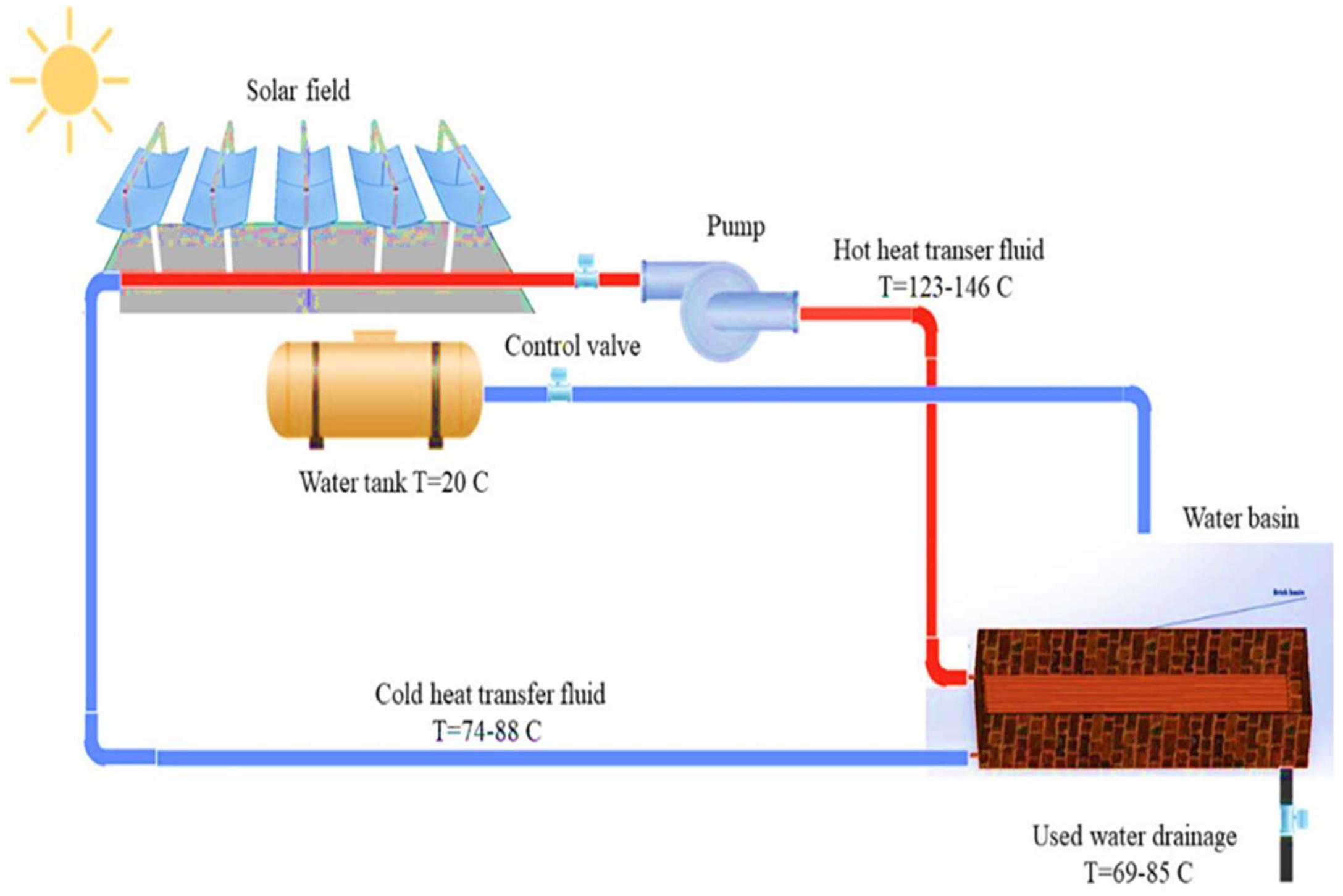
Figure 2.
The water pool used for wool washing.
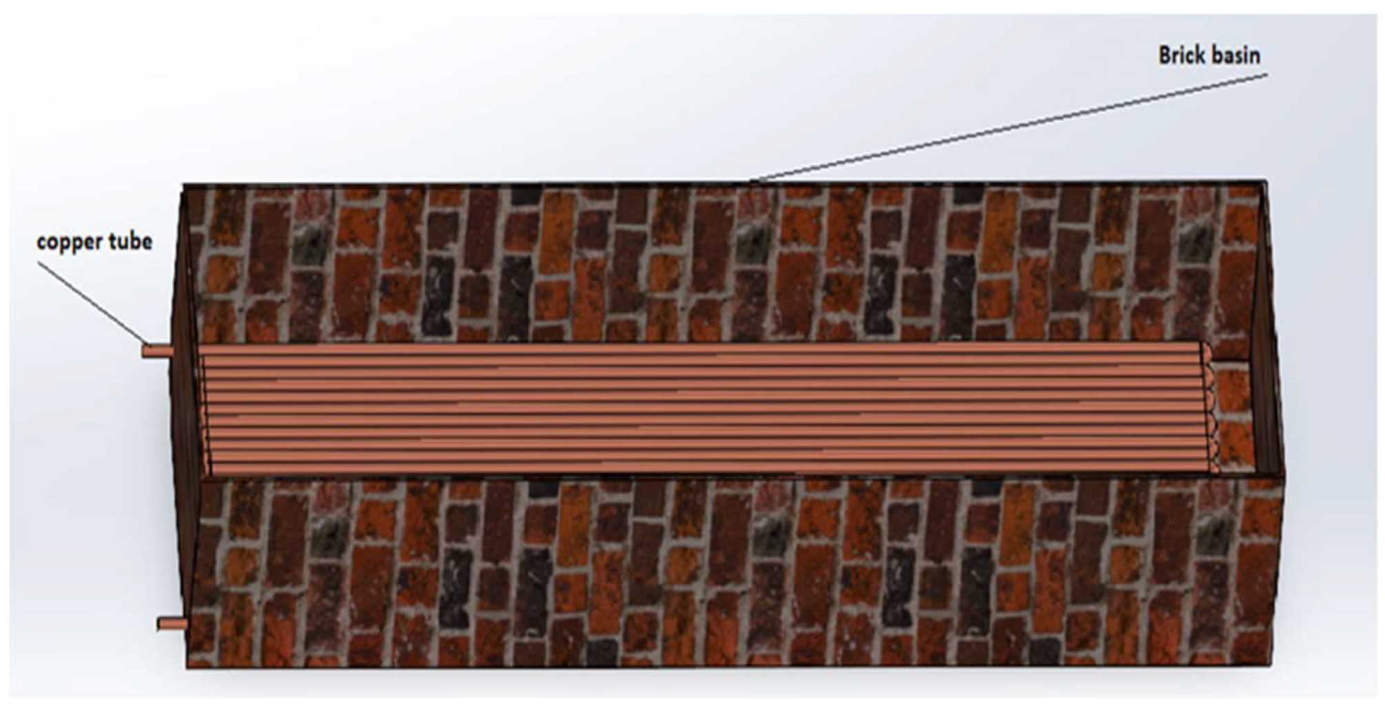
Figure 3.
Typical computational mesh for numerical analysis.

Figure 4.
Meshing test (case Thermia B).
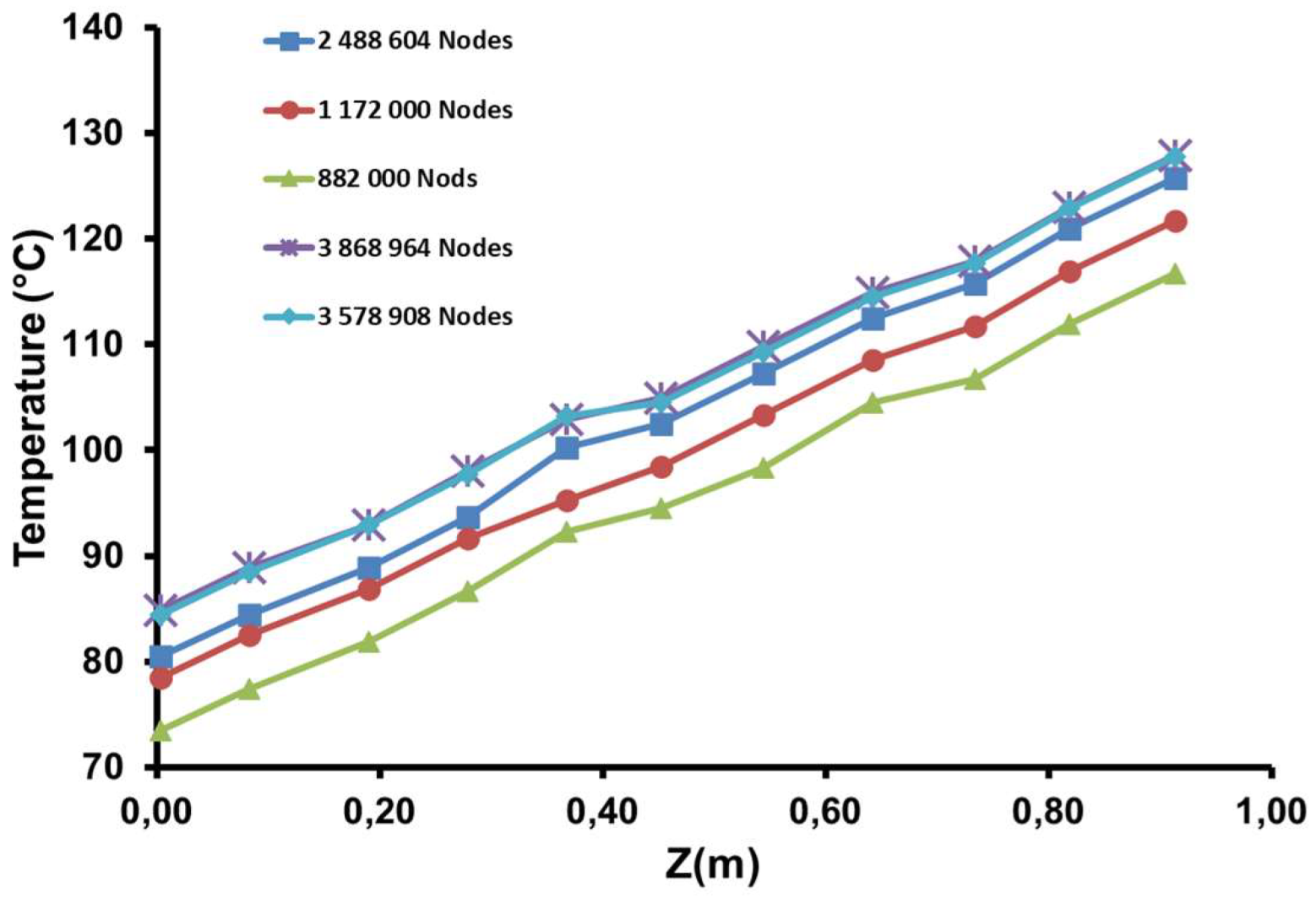
Figure 5.
(a) Evolution of water temperature in the brick pool with. (b) Evolution of water temperature in the brick pool without steel layer.
Figure 5.
(a) Evolution of water temperature in the brick pool with. (b) Evolution of water temperature in the brick pool without steel layer.
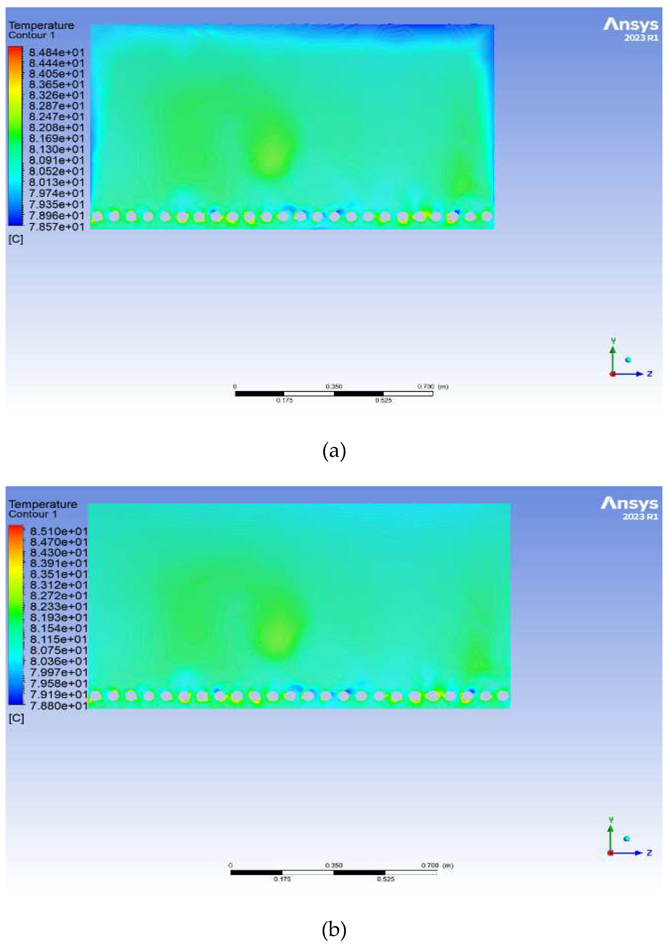
Figure 6.
(a) Temperature distribution of heat transfer oil 32 inside copper tubes. (b) Temperature distribution of biphasic oil inside copper tubes. (c) Temperature distribution of thermia B inside copper tubes. (d) Temperature distribution of therminol vp1 inside copper tubes.
Figure 6.
(a) Temperature distribution of heat transfer oil 32 inside copper tubes. (b) Temperature distribution of biphasic oil inside copper tubes. (c) Temperature distribution of thermia B inside copper tubes. (d) Temperature distribution of therminol vp1 inside copper tubes.
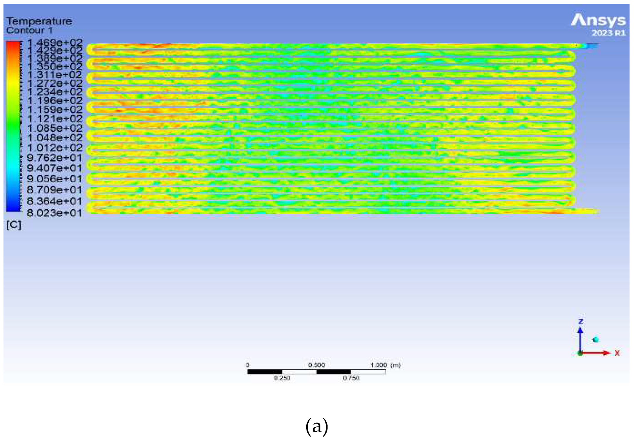
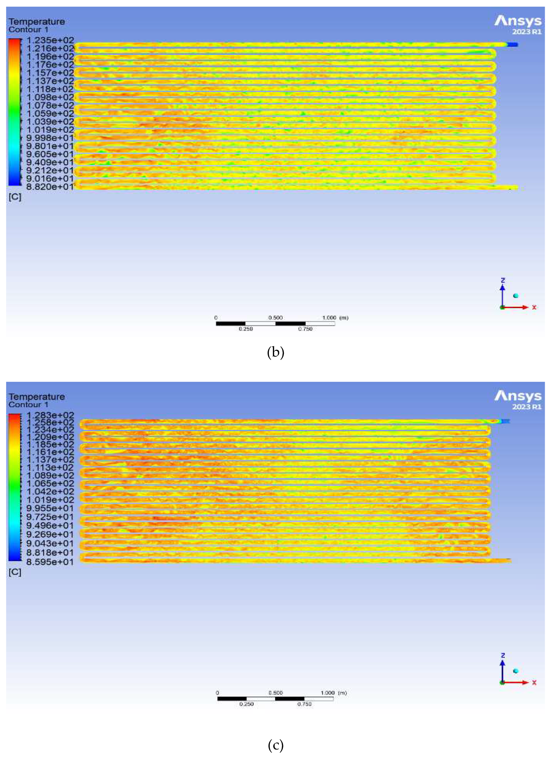
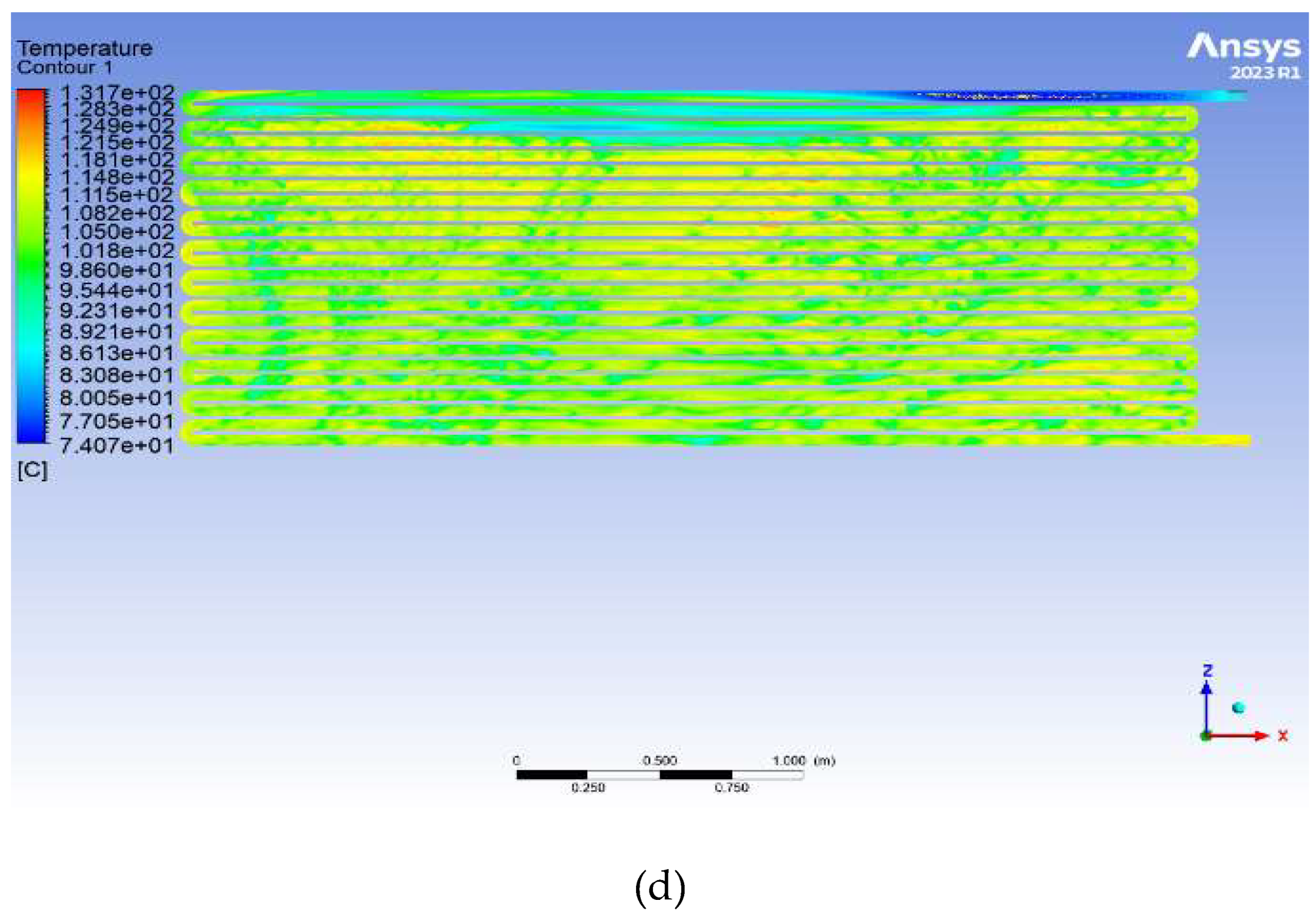
Figure 7.
Transversal variation of the oil temperature inside the tube.
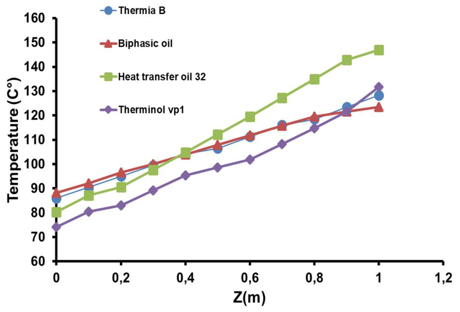
Figure 8.
Maximum and minimum temperatures of tested oils.
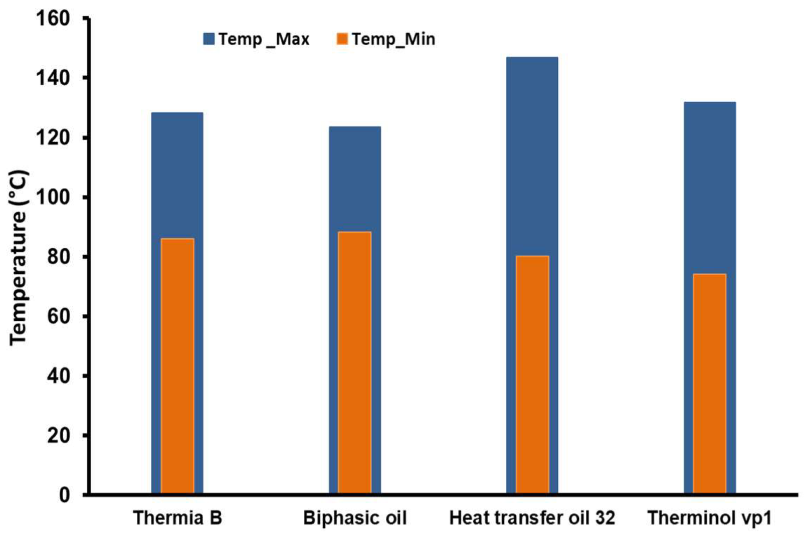
Figure 9.
(a) Distribution of water temperature by using heat transfer oil 32. (b) Distribution of water temperature by using biphasic oil. (c) Distribution of water temperature by using thermia B. (d) Distribution of water temperature by using therminol vp1.
Figure 9.
(a) Distribution of water temperature by using heat transfer oil 32. (b) Distribution of water temperature by using biphasic oil. (c) Distribution of water temperature by using thermia B. (d) Distribution of water temperature by using therminol vp1.

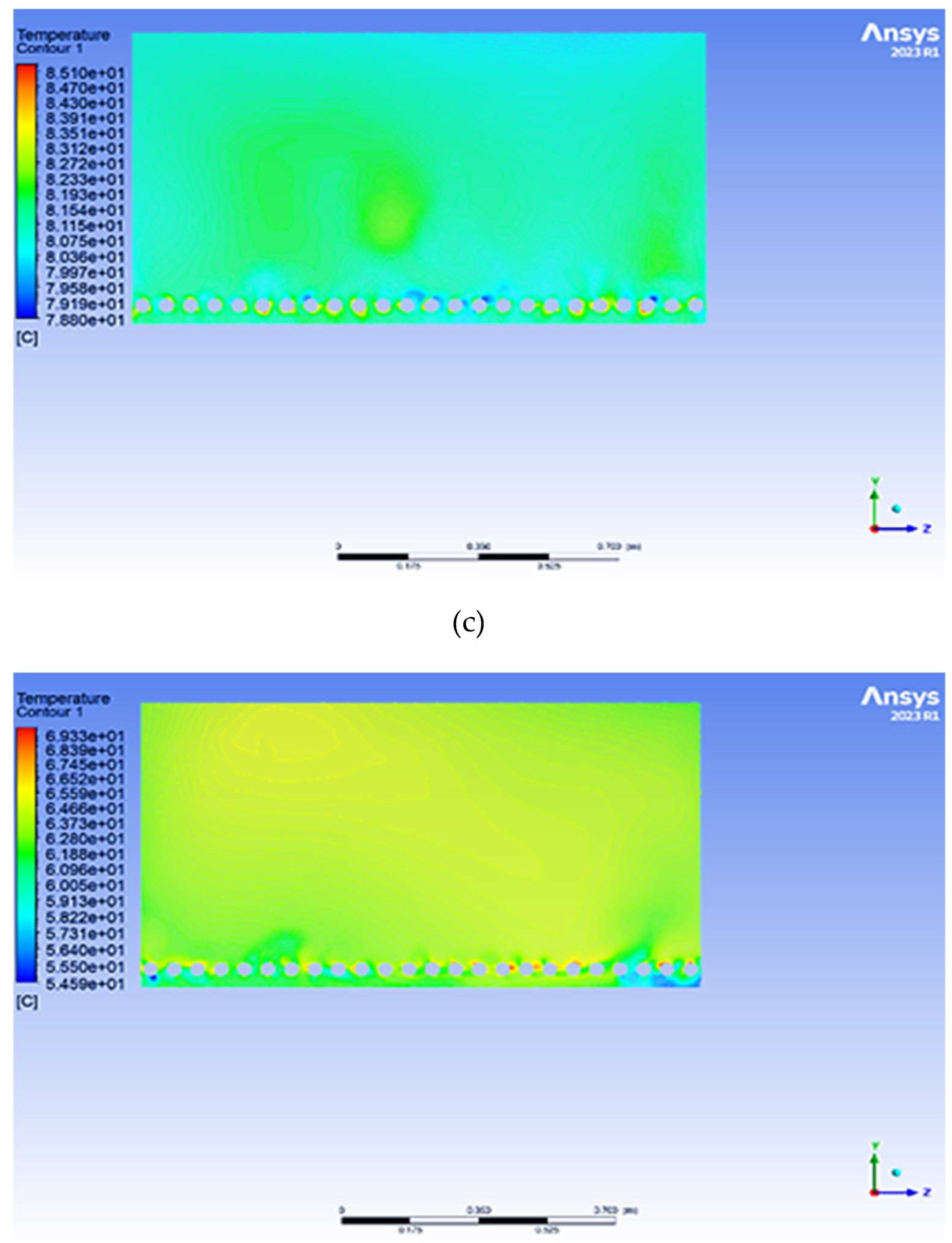
Figure 10.
Water temperatures under each synthetic oil.
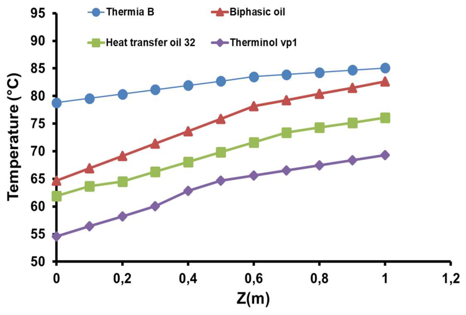
Figure 11.
The maximum and minimum water temperatures.
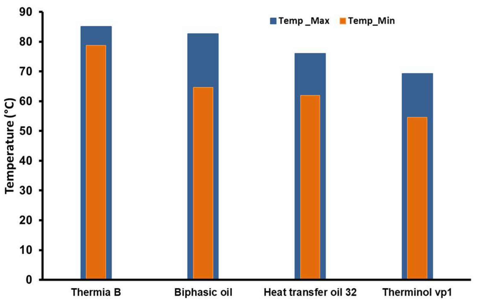
Figure 12.
The different outlet oils velocity.
Disclaimer/Publisher’s Note: The statements, opinions and data contained in all publications are solely those of the individual author(s) and contributor(s) and not of MDPI and/or the editor(s). MDPI and/or the editor(s) disclaim responsibility for any injury to people or property resulting from any ideas, methods, instructions or products referred to in the content. |
© 2025 by the authors. Licensee MDPI, Basel, Switzerland. This article is an open access article distributed under the terms and conditions of the Creative Commons Attribution (CC BY) license (http://creativecommons.org/licenses/by/4.0/).
Copyright: This open access article is published under a Creative Commons CC BY 4.0 license, which permit the free download, distribution, and reuse, provided that the author and preprint are cited in any reuse.


