1. Introduction
High voltage refers to electrical systems with voltages considerably higher than the standard levels, typically greater than 1,000 VAC or 1,500 VDC, and is required to efficiently transmit and distribute power over long distances. High voltage technology development started in the late 19th century with the “war of the currents” between AC and DC systems. In other respects, by having electricity transmit at high voltages it took very much less juice at the origin, due in large part to Tesla’s alternating current technology. Thus began Germany’s first high voltage-transmission line in 1891 at a transmission level of 15 kV. Voltage levels continued to increase throughout the 20th century, with the introduction of EHV lines in the middle of the century and UHV systems in recent decades, especially in countries like China, to transport electricity from faraway power sources to urban centers. Contemporary high-voltage systems are in continuous development to integrate advanced materials and technologies that contribute to better safety, efficiency, and reliability for power grids across the globe [
1].
Traditional methods for lightning protection frequently depend on electro-geometrical models to forecast the distribution of the electric field around lightning conductors. Although these models are computationally efficient, they intrinsically overlook the effects of the electrical characteristics of the grounding system [
2]. Notably, these characteristics, especially the conductivity and permittivity of the grounding medium, play a crucial role in determining the locations where lightning will connect with a structure [
3,
4]. Comprehensive studies have been undertaken to clarify the influence of electrical grounding characteristics on the distribution of electric fields in lightning conductors under different grounding setups [
5,
6,
7]. Such electric field distributions signify regions with the greatest likelihood of a lightning occurrence. Research has indicated that, in contrast to the forecasts made by traditional electro-geometrical models [
8,
9,
10], the actual electric field may be considerably greater for lightning conductors placed on non-uniform heterogeneous or heterogeneous grounding systems, which more accurately reflect real-world conditions than the ideal, perfectly conducting plane typically posited in theoretical frameworks [
11,
12,
13,
14].
To gain a deeper understanding of the changes in electric field distribution, the electrical properties of rod-air gap configurations under negative lightning impulse voltage have been investigated for both heterogeneous and homogeneous grounding conditions. The results of these investigations showed that the discharge phenomena differ significantly from those observed in configurations with a perfectly conducting homogeneous ground plane [
15,
16,
17,
18]. This phenomenon takes place because of the non-uniform characteristics and discontinuities within the grounding system, which make the path of least resistance for the lightning current much different and thus alter the distribution of the electric field around the lightning conductor [
19,
20,
21]. Among the different numerical modeling options, the Finite Element Method (FEM) will be employed. FEM is a well-known, powerful tool in high voltage engineering to deal with electrostatic field problems [
22]. The algorithm is exceptionally good at performing an electric field distribution between electrodes with a variety of intervening space containing different dielectric material-insulators with differing electrical properties [
23]. This also makes FEM particularly useful for the analysis of complex grounding configurations where conductivity and permittivity are very much variant in the system [
24,
25]. The key idea behind the basis of FEM utilizes a variational principle, seeking the minimum total system energy, and is thus equivalent to the governing equation of electrostatics, which is Laplace’s equation. The accuracy of the electric field configurations computed herein will be verified by cross-comparison with measurements extracted from controlled laboratory experiments utilizing a rod-plane air gap configuration [
26]. The incidence of lightning strikes presents a considerable hazard to high-voltage transmission and distribution networks. Conventional lightning protection systems, which are frequently grounded in empirical models, may fail to sufficiently address the intricate interactions that occur between lightning, the structural components, and the adjacent ground.
The main objective of the present study is to investigate, analyze, and discuss ground discontinuities’ influences on the electric field arising from a lightning conductor. In presenting how ripples in ground conductivity and permittivity affect the field, we aim to have an improved design of protection systems with reduced chances of structure damage due to strike incidences.
The present study extends the existing research by investigating the electric field distribution surrounding horizontal and vertical lightning conductors located on heterogeneous grounding systems. A complex approach will be used in this investigation, with both experimental and numerical models being considered. The main goal of this research is the validation of a numerical model realized by FEM for simulation of electric field distribution under lightning impulse voltage in real configuration with heterogeneous grounding. Then, this model will be used for the study of more complicated lightning protection problems. By incorporating the effects of heterogeneous grounding systems into our modeling frameworks, we are able to refine the accuracy of lightning protection assessments and further develop the establishment of protection strategies for real structures.
2. Materials and Methods
This section outlines the overall approach used in the study. It includes the objectives of the research, the theoretical framework underpinning the investigation, and a description of the experimental procedures employed.
2.1. Experimental Setup
The heterogeneous grounding system to be studied in this work is a square metal sheet with a thickness of 4 mm that serves as the “heterogeneous ground” in this study. This sheet consists of two separate surface levels, each measuring 1 meter by 1 meter, as illustrated in
Figure 1a,b. In order to simulate a lightning discharge during its final jump, a 4.8 mm diameter iron rod is used. This rod is connected to a lightning impulse generator capable of providing a pulse of 600 kV and 4 kJ. The position of the rod is controlled with great precision by two parameters: its height (h) relative to the grounding system and its horizontal distance (D) from the point where the two levels meet. A positive value of D denotes the rod’s location at an elevated level, whereas a negative value represents its placement at a lower level. The variations in height (h) correspond to those applied in homogeneous configurations (uniform grounding), thereby establishing a stable baseline for comparative analysis. The selected horizontal distances (d and D) are intended to preserve uniform ratios of d/h and D/h across varying h values. The developed method ensures the same number of configurations to be analyzed for investigation. To avoid destructive discharges around the probes due to high currents, one might use a possible voltage of 0.3U
0 % for each chosen height, h, of the rod (U
0 % is the breakdown voltage for the equivalent rod-plane configuration). This value of voltage is the same regardless of whether the rod is positioned in the top or bottom portion of the inhomogeneous plane. To achieve the required test voltage of 0.3U
0 %, the breakdown voltage, U
0 % is determined by a consistent multiple steps approach using Gaussian arithmetic scale paper. This research work covers all types of possibilities, including horizontal and vertical lightning conductors facing both high and low-level configurations on the heterogeneous earth.
2.2. Modeling and Analysis [27,28]
This paper deals with the modeling and study of electric field distribution in rod-plane air gaps subjected to negative lightning impulse voltage. The main methodology adopted for this study is the FEM to model electric field distributions. The governing equations derived from electrostatics, particularly Laplace’s equation given by:
where V is the electric potential. This equation describes how the potential varies in space, which is crucial for understanding electric fields. In electrostatics, the electric field E can be derived from the potential as:
This relationship allows researchers to calculate electric field strengths based on the potential distribution, making it essential for modeling scenarios involving lightning conductors.
The electric charge density and the total electric charge on a specific surface S, or within the volume enclosed by surface S, are calculated using equations:
where ρ: Space charge density in C/m
3, ε
0: Medium dielectric constant, D: Dielectric displacement.
The paper highlights the critical role of boundary conditions and mesh density in the accuracy of numerical simulations used to predict electric field distributions in lightning protection systems. Specifically, it discusses the governing equation for applied voltage in relation to rod geometry, expressed as:
where, U: Applied voltage, L: Gap length, r: Radius of the rod’s tip. The plan’s diameter is big enough.
The effectiveness of the numerical model is heavily influenced by how boundary conditions are defined. These conditions dictate how the electric fields interact with the surrounding environment, particularly in heterogeneous grounding scenarios. Accurate boundary conditions ensure that the simulations reflect real-world behavior, allowing for reliable predictions of electric field distributions around lightning conductors.
The mesh density refers to how finely the computational domain is divided into smaller elements for analysis. A higher mesh density typically leads to more accurate results because it allows for better resolution of electric field variations, especially near critical areas such as conductor tips or ground discontinuities. Conversely, a coarse mesh may overlook important details, leading to inaccuracies in predicting electric field strengths and potential discharge paths.
The findings from these equations suggest that electric field distributions near lightning conductors can vary significantly based on ground characteristics. For instance, when examining configurations with different distances between conductors and ground discontinuities., the results indicate the ratio(E/E0) equal unit , the electric field strength with heterogeneous grounding configurations (E) approaches a constant value of the electric field strength with homogeneous grounding (E0), suggesting diminishing influence from nearby structures.
3. Results
The paper studies the effect of different heterogeneous grounding configurations on the electric field distributions around the lightning conductors. These heterogeneous grounding configurations represent a more realistic model of actual grounding conditions compared to a homogeneous (uniform) earth model. The present analysis is based on combines both experimental and simulation methods, that uses a flat metallic sheet to simulate a heterogeneous earth, as shown in
Figure 2. The electric field distribution obtained from this setup will be compared with the theoretical distribution expected for a homogeneous earth model. This comparison will highlight the effect of irregularities within the grounding system on the behavior of the electric field and, consequently, on the performance of lightning conductors. Through the comparative analysis of these electric field distributions, researchers are able to obtain a deeper understanding of the manner in which the complexities inherent in grounding systems, characterized by the heterogeneous earth, diverge from the idealized conditions and how such divergences may influence the dynamics of lightning strikes as well as the efficacy of lightning protection systems.
3.1. Electric Field Distribution Analysis on Homogeneous Conductor Earth
This section looks into the distribution of electric fields around lightning conductors in a homogeneous grounding system-ideal conducting plane earth, serving as a reference for assessing the effects of a heterogeneous grounding system as shown in
Figure 3a,b. The study focuses on both Very Low Conductivity and High Level Conductivity systems. The height of the conductor, h, above the high voltage rod is a key variable. A standard voltage level of 0.3U
0 % is used for consistency. As the horizontal distance (D) between the lightning conductor and the high voltage rod increases (D/h ≥ 2), the electric field strength approaches a constant value. This suggests that the influence of the rod on the electric field is minimal at larger distances. Understanding the electric field distribution in a homogeneous earth provides a basis for comparison. As the grounding system becomes heterogeneous, the distribution of the electric field will deviate from the established reference behavior. The present study focuses on these deviations and their possible effects on the performance of lightning conductors in more realistic grounding scenarios.
The equipotential lines around the rod are concentrated, and hence there is a strong and non-uniform electric field. The maximum value of the field is on the surface of the rod facing the grounded plane, and this is because the opposite charges are attractive in nature. This was also expected for a lightning rod arrangement.
3.2. Electric Field Distribution with Heterogeneous Earthing: Lightning Conductor on High Ground
Electric field distribution has been evaluated for various D/h ratios (ratio of horizontal distance to conductor height) in two primary configurations
Figure 4a,b. When the measuring probe is located far from the discontinuity between the two levels of ground (large D/h ratio), the recorded electric field strength on the upper part of the inhomogeneous earth closely follows the field distribution in a homogeneous grounding system with a conductor of equal length. This observation indicates that at greater distances, the effect of the irregular ground on the electric field behavior is almost insignificant. When the probe is placed closer to the interface ((d/h < 2), the results obtained show a distinct discontinuity in the electric field distribution. Such discontinuity favors the operational effectiveness of the lightning conductor. The positioning of the conductor close to the discontinuity essentially transforms the “rod-plane” configuration into a “rod-rod” configuration. This can explain the following observations: The electric field intensity directly below the lightning conductor is substantially reduced. Corresponding to the increased rigidity of the Rod-Plane Gap, the path for electrical discharge from the rod to the ground plane becomes more rigid due to the new distribution of the field. These results are in good agreement with those obtained in previous work where the occurrence of discharge phenomena was reported under similar conditions. That would therefore mean that, even for moderate D/h values, a lightning strike may have the tendency to jump towards the lightning conductor rather than take a direct course towards the lower ground plane. The intervening space between the rod and the lightning conductor becomes a more favorable path for the electric field lines due to the modified field distribution.
The rod-lightning conductor configuration works as a point-to-point system, offering a path of less resistance compared to the original “point-to-plane” configuration. Therefore, disruptive discharges can occur periodically on the lightning conductor, especially for the lower D/h ratios. Besides, the presence of a non-uniform grounding system significantly influences the electric field distribution, mainly at the border of different ground levels. Therefore, this affects the possible directions of lightning strikes and points out the importance of considering real conditions of grounding in the design and verification of lightning protection systems.
3.3. Numerical Computations by Using FEM Method
The study emphasized the fact that real grounding systems are often heterogeneous, implying their electrical properties vary due to soil composition, moisture content, and other environmental influences. This is an important fact since the electric field distribution around lightning conductors may, under these conditions, seriously deviate from predictions obtained by conventional homogeneous models.
The results show specific configurations of lightning conductors which perform better under different soil resistivity conditions. It is found, for instance, that at certain spacing to height ratios (D/hc), the electric field strengths are significantly lower; this would imply optimal positions of ²conductors where potential ground rise and safety may be improved upon the occurrence of lightning strikes.
The study highlights the influence of inconsistencies in grounding systems on discharge behavior. For example, when the horizontal separation between the conductor and the ground interface is reduced, the electric field distribution becomes more favorable for the interception of lightning strikes. This conclusion may be useful to engineers in developing systems that enhance the probability of safe discharge paths for lightning currents. Numerical simulations in this study were made using COMSOL Multiphysics.
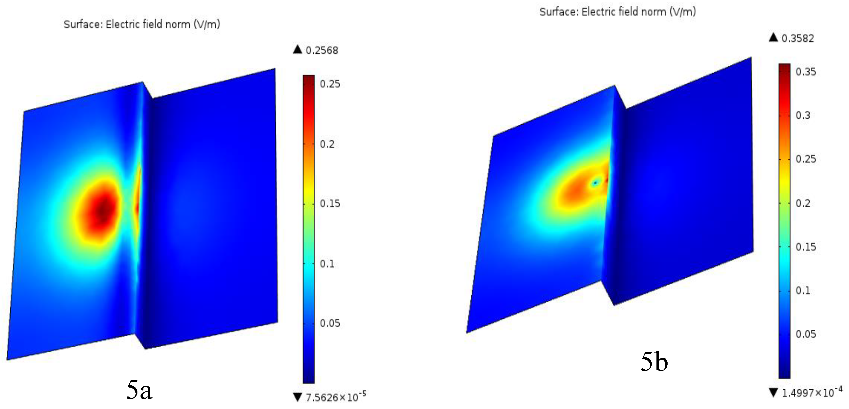
The electric field within the rod-plane configuration shown in
Figure 5 is obtained by applying initial and boundary conditions, which are two very important parameters that define the limits and starting points of a simulation. They are essential inputs that drive the dynamics of the system under modeling. Boundary conditions describe the behavior of the system at its edges or surfaces. Neumann conditions require the derivative of the voltage at the boundary to be zero. On the other hand, Dirichlet conditions require the voltage value to be specified at the boundary, which is taken as 1 Volt over a distance of 16 cm in free air at atmospheric pressure. In theoretical considerations, voltage can be of lesser magnitude to simplify the calculations and underscore the principals involved without losing the essential features of the phenomenon. This is particularly useful when studying the propagation of electrical discharges or the interaction of lightning with the atmosphere. The initial condition, before the application of voltage, is that there is no charge in the space shown in
Figure 5.
Figure 5 shows the calculated distribution of the electric field in the heterogeneous plane when the rod is placed at the top of the plane. Electric field measurements have been verified for numerous distances between the rod and the interface. The peak value of the electric field was easily obtained from the surface plot provided by the FEM program at the end of each computation.
The electric field distribution of the horizontal and vertical lightning rod is shown in
Figure 5. The horizontal conductor presents a wider field distribution; its intensity decreases with distance from the conductor. On the contrary, the vertical conductor provides more focused electric field configurations closer to the conductor. This suggests that vertical conductors are more effective in carrying lightning currents and reducing the effects of lightning, due to the concentrated electric field distribution.
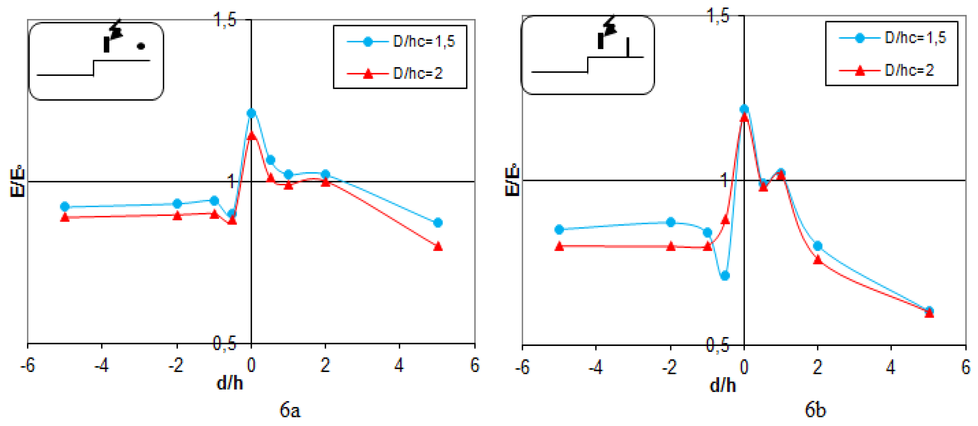
3.4. Lightning Discharge
Figure 6 illustrates the discharge occurring between the vertical lightning rod (
Figure 6a) and the horizontal lightning rod (
Figure 6b) with respect to the terrestrial discontinuity. The findings indicate that when the lightning rod is situated in proximity to the terrestrial discontinuity (D/hc = 1.5), the distribution of the electric field diminishes in strength in comparison to the model that lacks the lightning rod. In contrast, with a D/hc ratio of 3.5 or above, the electric field strength becomes close to that of the model without a lightning rod and reflects the fact that for larger distances the interface exerts an insignificant influence on the attraction of discharges.
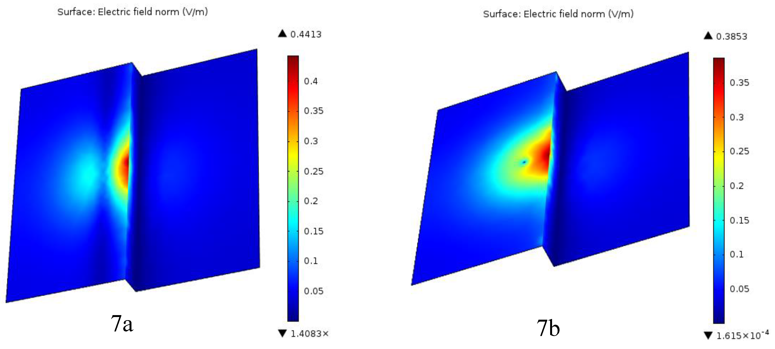
Figure 7a,b, obtained from FEM analysis, show that equipotential lines are heavily concentrated around the interface. Therefore, the field distribution becomes highly inhomogeneous over space. The field intensity on the interface surface is at its maximum value. This methodology has been validated by several experimental studies which show that the field strengths computed are below those actually measured, and this leads to a conservative assessment, which can be adopted in the design of protection distances.
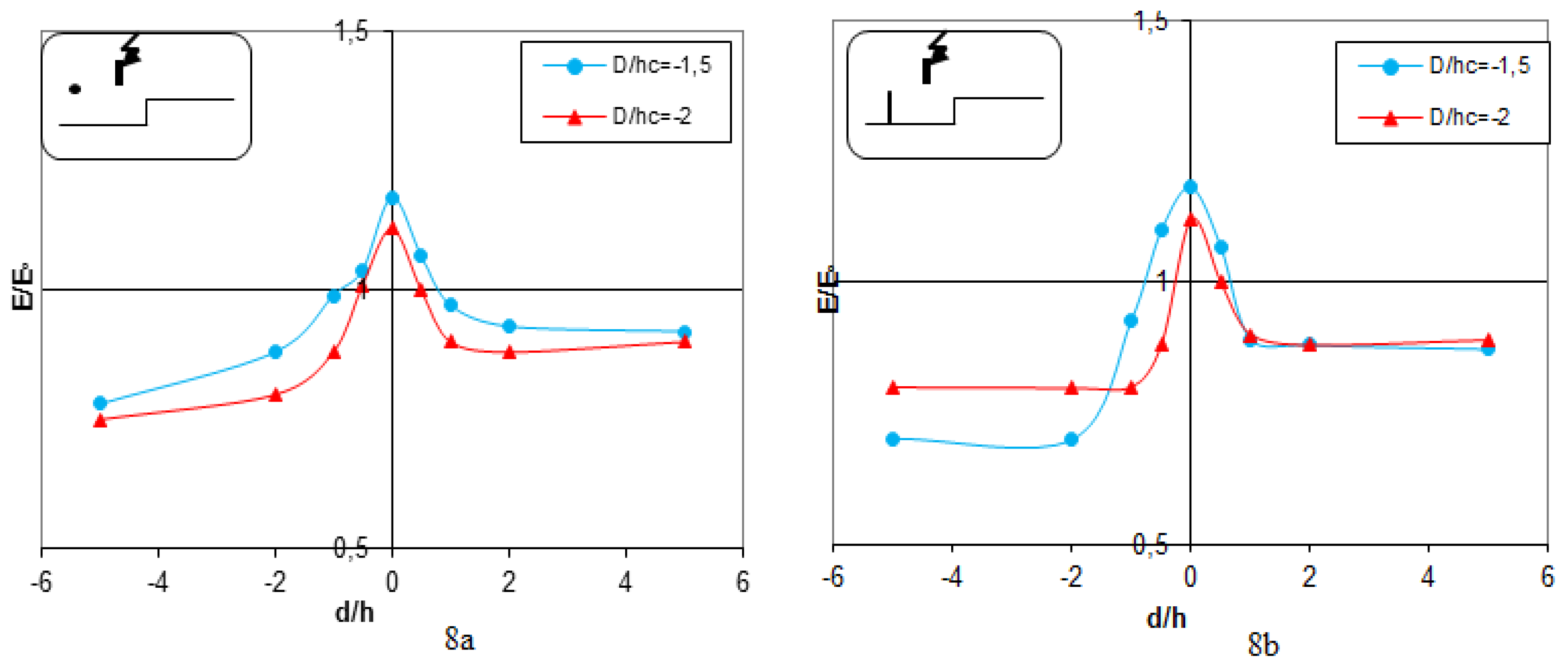
Figure 8 shows that the lightening rod is located in the bottom part of the soil and the high voltage lightning rod is positioned between the soil discontinuity and the major lightning rod. The results show that the electric field intensity within the bottom part of the heterogeneous soil is smaller than in the top part owing to the increased distance that exists between the lightening rod and the probe. The electric field attains its minimum value on the plane near the interface.
Furthermore, it is shown that when the vertical (
Figure 8a) or horizontal (
Figure 8b) lightning rod is moderately close to the ground discontinuity (D/hc = 1.5), the electric field distribution enhances in intensity.
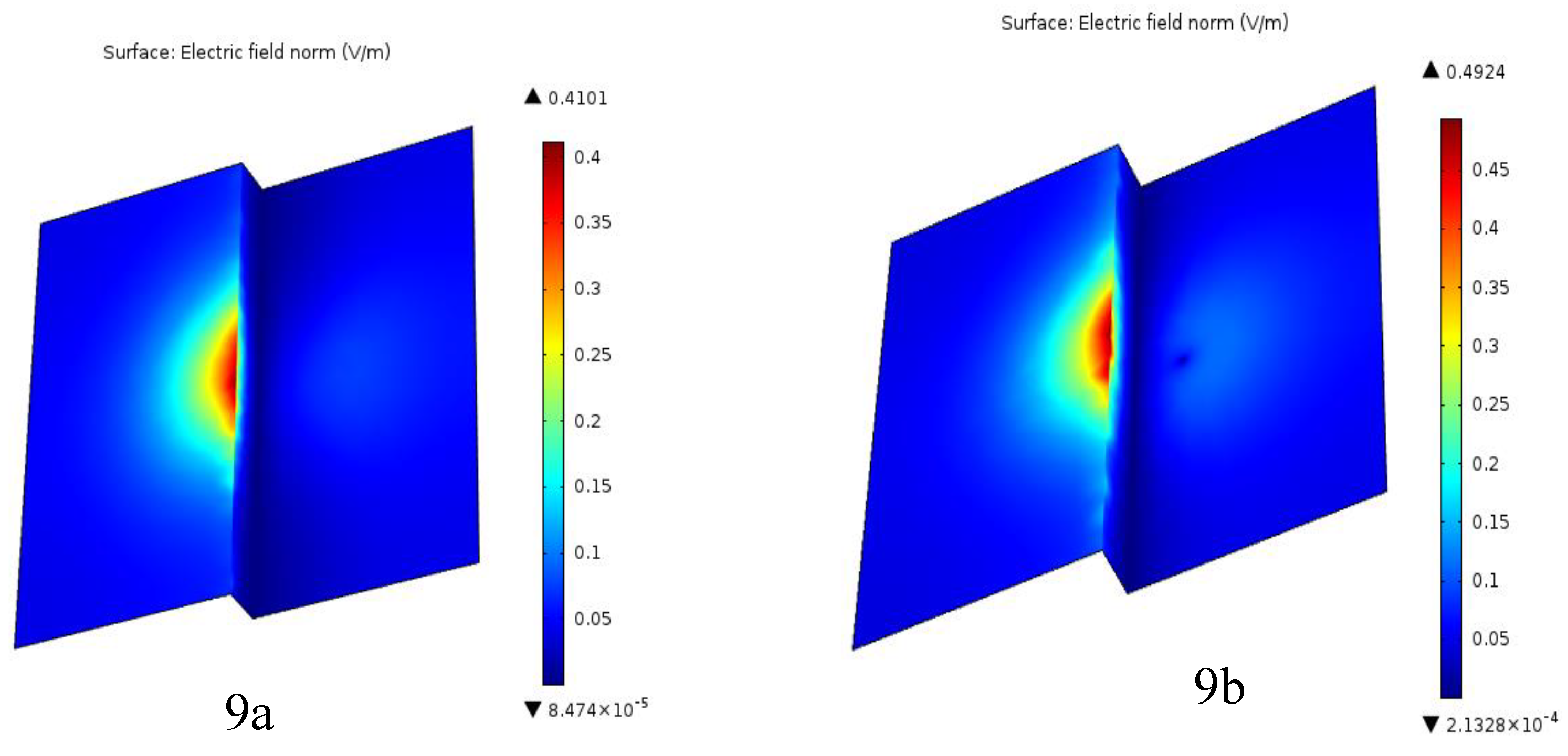
However, if the D/hc ratio reaches or exceeds 2.5, the electric field intensity becomes equal to the model without a lightning rod. At the interface height, the lightning rod-interface configuration acts like a rod-rod geometry, that shows lower stiffness than the rod-plate configuration. It has its maximum relation value, E/E
0 = 1.25, at which the occurrence of disruptive discharges is most expected just at the interface (see
Figure 9a,b).
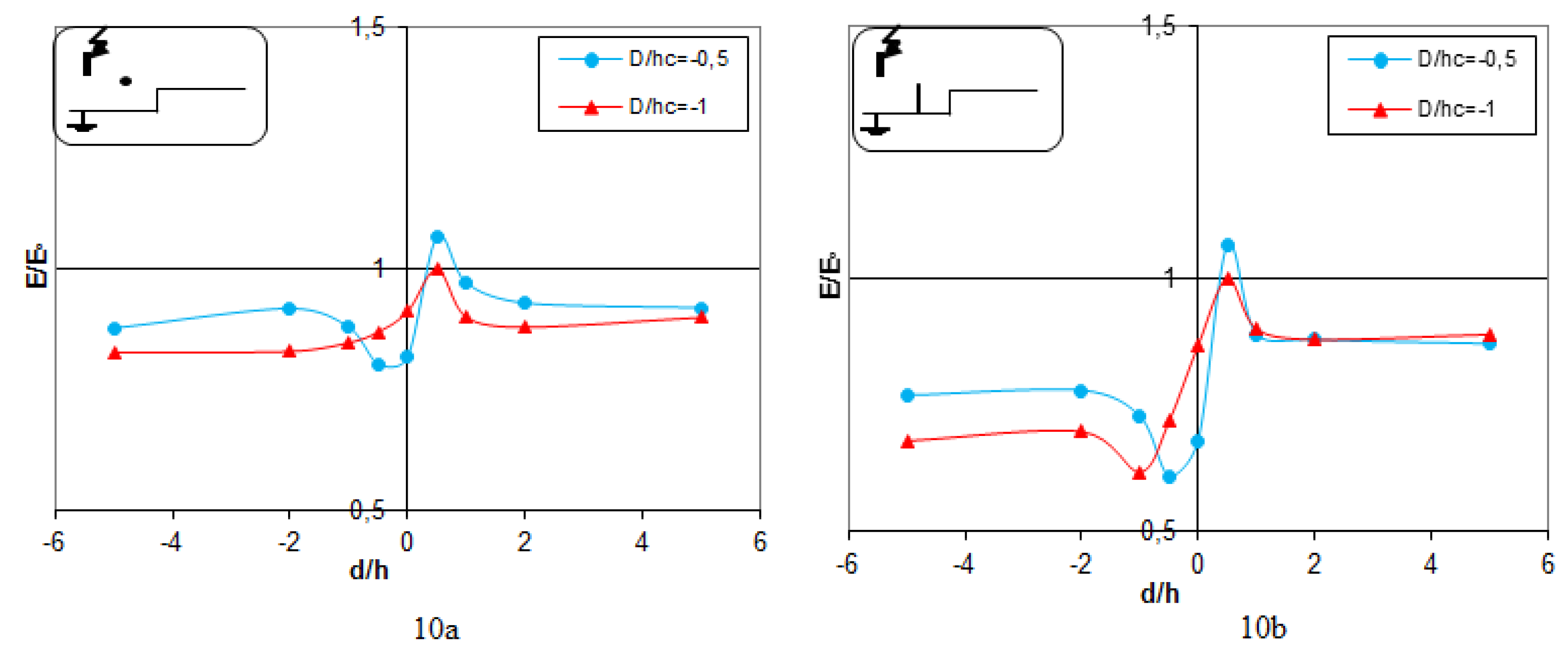
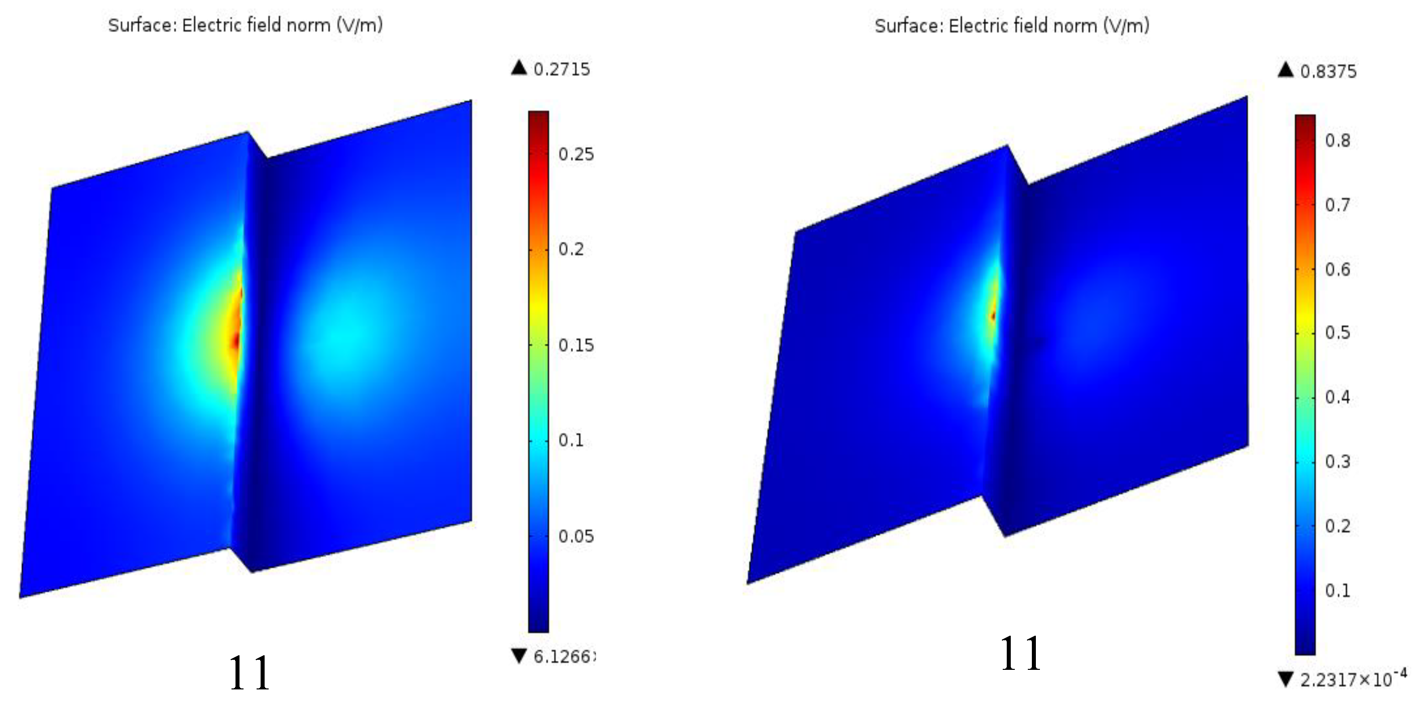
3.5. Lightning Conductor Located
Figure 10 illustrates the location of the lightning rod located at the bottom of the heterogeneous soil, placed between the high-voltage lightning rod and the discontinuity of the soil. The investigation into the electric field intensity related to the vertical lightning rod (
Figure 10a and
Figure 11a) and the horizontal (
Figure 10b and
Figure 11b), in this configuration, finds a relation with the results of the second configuration presented earlier in the paper. That means the electric field distribution around the lightning rods does not depend on their orientation when positioned in such a configuration with respect to the discontinuity of the ground. The results obtained show that the intentional placement of the lightning rods between the high-voltage source and the discontinuity of the ground maintains the same features of the field, outlining the importance of considering ground heterogeneity in the improvement of lightning protection systems.
4. Discussion
A comparative examination of electric field distributions surrounding lightning rods in both homogeneous and heterogeneous grounding systems uncovers significant variations that affect the efficacy of lightning protection. Within the homogeneous system (
Figure 3a,b), the intensity of the electric field tends to be relatively consistent at greater distances (D/h ≥ 2), establishing a reference point for analyzing the behavior of the field around lightning rods. However, with the introduction of heterogeneous grounding, as shown in
Figure 4,b, the electric field exhibits strong discontinuities at the interface, especially for reduced D/h ratios (D/h < 2). This discontinuity reconfigures the “rod-plane” arrangement into a “rod-rod” configuration, which influences the trajectory of the electric field and the phenomena of discharge, indicating a tendency for lightning strikes to preferentially target the conductor as opposed to the lower ground plane. Numerical simulations performed by the finite element method, presented in
Figure 5a,b, also show that vertical conductors generate a more concentrated electric field near the conductor (E=0.35 V/m), which makes them more effective in carrying lightning currents compared to horizontal conductors (E=0.25 V/m). Upon adjusting the position of the lightning rod in relation to the ground discontinuity (
Figure 10 and
Figure 11), the patterns of field intensity (E=0.15 V/m) remain stable, underscoring the critical role of strategic positioning in enhancing lightning protection systems. The findings demonstrate that the complexities inherent in heterogeneous grounding systems substantially modify the distributions of the electric field, necessitating thorough contemplation of these elements in the formulation of lightning protection strategies. This research has examined the effect of geological discontinuities on the distribution of the electric field surrounding both vertical and horizontal lightning conductors. By manipulating the distance ratio (D/h) that exists between the conductor and the interface of the discontinuity, we have acquired significant understanding regarding the dynamics of lightning strikes on non-uniform ground; this distance notably influences the distribution of the electric field, thereby impacting the probability of lightning strikes. The varied ground conditions can drastically alter the electric field configurations, leading to unexpected behaviors and potential weaknesses in lightning protection systems. Based on that, knowledge of the role of ground discontinuities helps engineers in improving the placing of conductors for lightening to work effectively. These are development of grounding systems and would consider any probable effects which ground heterogeneity may play in functionality within lightning protection systems. The validated model is then used to perform a series of simulations corresponding to a variety of possible lightning protection scenarios and tests the efficacy of different approaches to the design.
5. Conclusions
This paper presents the investigation of how earth discontinuities may affect the electric field distribution around very long conductors and horizontal long conductors for different D/h ratios. The results obtained indicate that for larger distances, the electric field assumes a homogeneous grounding system, and the discontinuity does not affect it much. However, for closer proximity, there exists a clear field discontinuity that is helpful in lightning conductor functionality, changing the system from “rod-plane” to “rod-rod” configuration. Numerical simulations revealed that the field intensity near the conductor was reduced when situated close to the discontinuity, and strong effects appeared for D/hc = 1.5. For D/hc ≥ 3.5, the field strength was found in agreement with models without a lightning rod, indicating negligible effect on discharge attraction. The research findings present some optimization insights into the design of lightning protection systems by considering the spatial relation between lightning conductors and earth discontinuities. The research represents an important understanding regarding the relation of different D/h ratios on the effectiveness of vertical and horizontal lightning rods, pinpointing the transition from a “rod-plane” to a “rod-rod” configuration at reduced D/h ratios, which enhances efficiency for the conductor. That is, the accumulation of electric field lines at the tip of a conductor enhances the electric field intensity in that particular point. This phenomenon, known as the ’point effect,’ is a fundamental principle of electrostatics. It explains why sharp points or edges have a greater tendency to attract electrical discharges, as utilized in the use of lightning rods. It is suggested by the research that proximity to ground discontinuities can reduce the field strength around the conductor, which can increase the overall effectiveness of the lightning protection system. The results obtained are important to improve the design and placement of lightning rods, with the assurance that protection systems would be altered to take into consideration discontinuities in ground, hence improving their effectiveness in practical applications. This research develops recommendations applicable in the design of lightning protection systems in scenarios where the ground conditions are not uniform. While numerical simulations presented in this study give valuable insight into the dynamics of lightning strikes on complex topography, the limitations of models and assumptions set should be born in mind. The models of the ground used here, while capturing the most salient features of real heterogeneous terrain, may not capture the complex electrical properties of real soils.
Experimental device and computational model dimensions might not be satisfactory to properly encompass complex phenomena of real lightning discharge, while the models developed for modeling lightning discharge need proper representation of the physics processes associated with the complex physics involved in the development and propagation of a lightning discharge.
References
- Kuffel, E.; Zaengl, W. S.; Kuffel, J. High Voltage Engineering Fundamentals. 2000 Newnes. ISBN : 978-0-7506-3634-6.
- Aslani, F.; Yahyaabadi, M.; Vahidi, B. A new-intelligent method for evaluating the lightning protection system performance of complex and asymmetric structures. Electric Power Systems Research 2021, 190, 106843. [Google Scholar] [CrossRef]
- Havran, P.; Cimbala, R.; Kurimský, J.; Dolník, B.; Kolcunová, I.; Medveď, D.; Király, J.; Kohan, V.; Šárpataky, Ľ. Dielectric Properties of Electrical Insulating Liquids for High Voltage Electric Devices in a Time-Varying Electric Field. Energies 2022, 15(1), 391. [Google Scholar] [CrossRef]
- Rahmani, A.; Khechekhouche, A.; Mekhaldi, A.; Boubakeur, A. Electrical Strength of Rod-Heterogeneous Plane Air Gap Under Lightning Impulse Applied Voltage Using a Distributed Capacity Probe. In IEEE-CEIDP 2012 (pp. 379-382). Montréal, Canada.
- Dimitropoulou, M.; Pylarinos, D.; Siderakis, K.; Thalassinakis, E.; Danikas, M. Comparative investigation of pollution accumulation and natural cleaning for different HV insulators. Engineering, Technology & Applied Science Research 2015, 5(2), 764-774. [CrossRef]
- Trlep, M.; Zidanšek, A.; Dolinar, D.; Štumberger, B. Nonlinear Transient Finite Element Analysis of Grounding Systems. 19th International Symposium on Electromagnetic Fields in Mechatronics, Electrical and Electronic Engineering (ISEF) 2019, pp. 1-2. IEEE.
- Khechekhouche, A.; Ben Attous, D. Effect of earth discontinuity on the electrical field distribution in rod-plane air gaps under lightning impulse. Journal of Fundamental and Applied Sciences 2016, 8(3), 1054–1065. [Google Scholar] [CrossRef]
- Syssoev, A. A.; Iudin, D. I.; Bulatov, A. A.; Rakov, V. A. Numerical simulation of stepping and branching processes in negative lightning leaders. Journal of Geophysical Research: Atmospheres 2020, 125(7), e2019JD031360.
- Beroual, A.; Rakotonandrasana, J.; Fofana, I. Predictive dynamic model of the negative lightning discharge based on similarity with long laboratory sparks. IEEE Transactions on Dielectrics and Electrical Insulation 2020, 17(5), 1551–1561. [Google Scholar] [CrossRef]
- Guo, X.; Ji, Z.; Gao, Y.; Zhang, L.; Lyu, W.; Ding, J.; Zhang, Y. Effects of positive corona on upward leader initiation from tall buildings by 3D numerical simulation. Atmospheric Research 2023, 291, 106822. [Google Scholar] [CrossRef]
- Talal, G.; Khechekhouche, A.; M’hamdi, B.; Khaled, F.; Abelhamid, N. M. Experimental measurement of electric field near the insulator string. studies in engineering and exact sciences 2024, 5(2), e11293. [Google Scholar] [CrossRef]
- Rahmani, A.; Boubakeur, A.; Brouri, H. Model of a horizontal lightning conductor protection in the case of earth discontinuity. In International Symposium on Electromagnetic Compatibility EMC EUROPE 2002,pp. 267-270. Sorrento, Italy.
- Zheng, C.; Zhang, X.; Yang, Z.; Liang, C.; Guo, Y.; Wang, Y.; Gao, X. Numerical simulation of corona discharge and particle transport behavior with the particle space charge effect. Journal of Aerosol Science 2018, 118, 22–33. [Google Scholar] [CrossRef]
- Lesaint, O.; Costeanu, L. Positive streamer inception in cyclohexane: Experimental characterization and cavitation mechanisms. IEEE Transactions on Dielectrics and Electrical Insulation 2018, 25(5), 1949–1957. [Google Scholar] [CrossRef]
- Kara, A.; Onal, E.; Kalenderli, O.; Mardikyan, K. The Effect of Insulating Barriers on AC Breakdown Voltage in Inhomogeneous Field. IEEE MELECON Mediterranean Electrotechnical Conference 2006(pp. 1206-1208). Benalmádena (Málaga), Spain.
- Barman, S. D.; Shah, R.; Islam, S.; Kumar, A. Numerical Model of Cloud-to-Ground Lightning for PyroCb Thunderstorms. IEEE Journal of Selected Topics in Applied Earth Observations and Remote Sensing 2023.
- Khechekhouche, A.; Benattous, D.; Mekhaldi, A.; Boubakeur, A. Electric field measurement in rod-discontinued plane air gaps using distributed capacity probe. Journal of Fundamental and Applied Sciences 2014, 6(1), 1–10. [Google Scholar] [CrossRef]
- De Oliveira, R. M. S.; Fujiyoshi, D. M. Finite-difference time-domain modeling of multi-stage soil ionization with residual resistivities—Part I: Theoretical background and the proposed FDTD formulation. Electric Power Systems Research 2020, 184, 106300. [Google Scholar] [CrossRef]
- Jang, K. H.; Seo, S. W.; Kim, D. J. A Study on Electric Potential and Electric Field Distribution for Optimal Design of Lightning Rod Using Finite Element Method. Mathematics 2023, 11(7), 1668. [Google Scholar] [CrossRef]
- Khechekhouche, A. The profile of the electric field on the earth discontinuity with a lightning conductor. International Journal of Energetica 2016, 1(1), 30–35. [Google Scholar] [CrossRef]
- Khechekhouche, A.; Guia, T.; Hima, A. Experimental investigation and modeling of the electric field distribution in lightning protection system. Journal of Fundamental and Applied Sciences 2019, 11(3), 1122–1134. [Google Scholar]
- Streamer Propagation in a Point-to-Plane Quast, M.; Lalic, N. R. Streamer Propagation in a Point-to-Plane Geometry. In Proceedings of the COMSOL Conference 2019.
- Betz, H. D.; Schumann, U.; Laroche, P. Lightning: Principles, Instruments and Applications - Review of Modern Lightning Research 2008. Springer. ISBN 978-1-4020-9078-3.
- Rizk, M. E. M.; Heidarzadeh, M.; Vahedi, A.; Nourbakhsh, G. Performance of large-scale grounding systems in thermal power plants against lightning strikes to nearby transmission towers. IEEE Transactions on Electromagnetic Compatibility 2018, 61(2), 400–408. [Google Scholar] [CrossRef]
- Karami, H. R.; Sheshyekani, K. Response to Comments on “Direct Characterization of Grounding System Wideband Input Impedance”. IEEE Transactions on Electromagnetic Compatibility 2018, 62(1), 298–298. [Google Scholar] [CrossRef]
- Singh, S. & Serdyuk, Y. Simulations of nonthermal electrical discharges in air over solid insulating barrier. IEEE Transactions on Plasma Science 2019, 47(1), 729–735. [Google Scholar]
- Khechekhouche, A.; Talal, G.; M’hamdi, B. Optimizing breakdown voltage in rod-plane gaps with barrier design for positive DC voltage: an experimental study. Brazilian Journal of Technology 2024, 7(4), e75931. [Google Scholar] [CrossRef]
- Bazelyan, E. M.; Raizer, Y. P. Lightning Physics and Lightning Protection. Institute of Physics Publishing (IOP), Bristol, UK, and Philadelphia 2020, USA.
Figure 1.
Configuration with Discontinuous Grounding. (a) HLC, (b) VLC
Figure 1.
Configuration with Discontinuous Grounding. (a) HLC, (b) VLC
Figure 2.
Configuration with Uniform Grounding System. (a) HLC, (b) VLC.
Figure 2.
Configuration with Uniform Grounding System. (a) HLC, (b) VLC.
Figure 3.
Experimental electric field distribution with uniform Grounding under Uapp=0.3U₀ % , E0=2.45kV/cm of the breakdown voltage with hc=16 cm (a) HLC, (b) VLC.
Figure 3.
Experimental electric field distribution with uniform Grounding under Uapp=0.3U₀ % , E0=2.45kV/cm of the breakdown voltage with hc=16 cm (a) HLC, (b) VLC.
Figure 4.
Experimental electric field distribution with heterogeneous Grounding under Uapp=0.3U₀ % and E0=2.45kV/cm of the breakdown voltage with hc=16 cm , 4a) HLC, 4b) VLC.
Figure 4.
Experimental electric field distribution with heterogeneous Grounding under Uapp=0.3U₀ % and E0=2.45kV/cm of the breakdown voltage with hc=16 cm , 4a) HLC, 4b) VLC.
Figure 5.
Computed Electric field distribution when the lightning conductor Positioned between lightning discharge rod and interface on the higher level of the heterogeneous Grounding, 5a) HLC, 5b) VLC.
Figure 5.
Computed Electric field distribution when the lightning conductor Positioned between lightning discharge rod and interface on the higher level of the heterogeneous Grounding, 5a) HLC, 5b) VLC.
Figure 6.
Experimental electric field distribution with heterogeneous Grounding under Uapp=0.3U₀ % and E0=2.45kV/cm of the breakdown voltage with hc=16 cm, 6a) HLC, 6b) VLC.
Figure 6.
Experimental electric field distribution with heterogeneous Grounding under Uapp=0.3U₀ % and E0=2.45kV/cm of the breakdown voltage with hc=16 cm, 6a) HLC, 6b) VLC.
Figure 7.
Computed Electric field distribution when the lightning conductor Positioned on the extremity of the higher level of the heterogeneous Grounding, 7a) HLC, 7b) VLC.
Figure 7.
Computed Electric field distribution when the lightning conductor Positioned on the extremity of the higher level of the heterogeneous Grounding, 7a) HLC, 7b) VLC.
Figure 8.
Experimental electric field distribution with heterogeneous Grounding under Uapp=0.3U₀ % and E0=2.45kV/cm of the breakdown voltage with hc=16 cm, 8a) HLC, 8b) VLC.
Figure 8.
Experimental electric field distribution with heterogeneous Grounding under Uapp=0.3U₀ % and E0=2.45kV/cm of the breakdown voltage with hc=16 cm, 8a) HLC, 8b) VLC.
Figure 9.
Computed Electric field distribution when the lightning conductor Positioned on the extremity of the low level of the heterogeneous Grounding, 9a) HLC, 9b) VLC.
Figure 9.
Computed Electric field distribution when the lightning conductor Positioned on the extremity of the low level of the heterogeneous Grounding, 9a) HLC, 9b) VLC.
Figure 10.
Experimental electric field distribution with heterogeneous Grounding under Uapp=0.3U₀ % and E0=2.45kV/cm of the breakdown voltage with hc=16 cm, 10a) HLC, 10b) VLC.
Figure 10.
Experimental electric field distribution with heterogeneous Grounding under Uapp=0.3U₀ % and E0=2.45kV/cm of the breakdown voltage with hc=16 cm, 10a) HLC, 10b) VLC.
Figure 11.
Computed Electric field distribution when the lightning conductor Positioned between lightning discharge rod and interface on the low level of the heterogeneous Grounding,11a) HLC, 11b) VLC.
Figure 11.
Computed Electric field distribution when the lightning conductor Positioned between lightning discharge rod and interface on the low level of the heterogeneous Grounding,11a) HLC, 11b) VLC.
|
Disclaimer/Publisher’s Note: The statements, opinions and data contained in all publications are solely those of the individual author(s) and contributor(s) and not of MDPI and/or the editor(s). MDPI and/or the editor(s) disclaim responsibility for any injury to people or property resulting from any ideas, methods, instructions or products referred to in the content. |
© 2025 by the authors. Licensee MDPI, Basel, Switzerland. This article is an open access article distributed under the terms and conditions of the Creative Commons Attribution (CC BY) license (http://creativecommons.org/licenses/by/4.0/).