1. Introduction
The Additive Manufacturing (AM) techniques are gaining an ever growing attention in many engineering applications due to their advantages in terms of endless possibilities to generate new designs impossible with other technologies, and – more recently – even with advantages in terms of reduction of cost and material waste [
1]. Among the numerous AM techniques, the material extrusion (ME, ASTM F2792 – 12) is particularly interesting for plastics [
2]: mostly known as Fused Filament Fabrication (FFF) or with the trademark name Fused Deposition Modeling™ (FDM, Stratasys, Inc.) is based on the deposition of a fused wire of a polymeric material on a plate and then, layer by layer, on the construction of the component by progressive addition of material [
3]. Besides the low cost of this technology, a main advantage of FFF lies in the way the material is used, that is by melting a thermoplastic, which allows extensive choices in terms of basic raw materials [
4], charged composites [
5], but also multifunctional metamaterials [
6] and sensorial [
7,
8].
The properties of components obtained by AM depend on a lot of different parameters, obviously the first being the nature of the material [
4], others related to the processing parameters [
9], and their combinations. Many researches were devoted, in fact, to examine the process parameters for several well-known plastics such as the widely spread PLA [
10,
11,
12], ABS [
13,
14,
15,
16], PC [
16], and ASA [
17]. Moreover the adhesion to the plate and between the layer is critical for the quality of FFF parts: this has been studied for example for ABS [
18] and PC [
18] also considering the effect of temperature.
Processing parameters, and their influence, are many and several studies were done; among the others, the main parameters of influence include the infill density and infill patterns [
11,
17], the layers thickness [
12,
14,
17] and the layers gap [
13]. Many papers consider the various parameters for an optimization, a review is given in [
19]
The infill pattern plays an important role and, even with simple linear pattern, it has demonstrated that the way the filament is deposited can have a significant influence on stiffness and strength of components built by FFF. An analysis of the influence of the orientation of the fused wire was carried out by many authors, among them Wu et al. with PEEK and ABS [
14], Somireddy et al. [
20] Ahn et al. [
13] Alaimo et al. [
21] Croccolo et al. for ABS [
15], Rajpurohit et al. [
22] Lanzotti et al. [
10] Dai et al. [
23] and Yilmaz et al. [
24] with PLA, Avalle et al. with PETG and PA12 [
25].
Therefore, since a typical infill is by stacked layers of parallel filaments it is natural to compare this type of structured arrangement equivalent to the stack of a classical laminated composite. The layered structure built by FFF can therefore be studied with methods used for composites since decades that form the so-called Classical Lamination Theory (CLT). The CLT is a homogenization method developed in the 20th century [
26,
27,
28] to predict the mechanical behavior of layered composites made assembling layers of reinforced polymeric matrix with various stacking, thicknesses, and fiber orientations. The idea, proposed some year ago by Casavola et al. [
29] and then used to characterize the behavior of layered FFF specimens or components by several authors and with different materials and different stacking. Somireddy et al. [
20] used the technique to study ABS cross-ply stacking at 0°, 45°, and 90° angles, and similarly with PLA in [
22,
24]; Musenich et al. [
8] considered the analysis of a conductive filament obtained by charging PLA with carbon nano-particles; Alaimo et al. [
21] considered more orientation but aligned filaments in all layers. Nasirov et al. [
30] compared the results from the CLT with a finite element model finding a good correlation between the models.
The analysis of the strength of layered specimens built by FFF can be carried out by using the failure criteria of composite materials. The study is more complex since the failure of composites relies on several failure criteria proposed since the mid-20th century. In [
25] Avalle et al. used the Tsai-Hill [
31,
32] and Tsai-Wu [
33,
34] criteria to model the failure of PETG and PA12. Musenich et al. [
8] similarly considered the PLA charged material with the Tsai-Wu failure criterion. Both found a good correlation with the experimental results.
In this work the results from experimental tests on layered specimens made of a fiber-reinforced polyamide are reported and analyzed. The specimens were built layered by FFF using a symmetric angle-ply configuration with variable orientations of the fibers. The experimental results clearly show the strong influence of fiber orientation on both stiffness and strength. The adoption of the CLT and of different failure criteria shows applicability of the method to forecast the mechanical properties of components built by FFF. The mechanical properties in terms of layer stiffness and strength could be identified for this purpose.
2. Materials and Methods
2.1. Mechanical Behavior of a Lamina and Laminate
Most composite materials are made of a stack of unidirectional or woven laminae. The mechanical behavior of a single lamina is typically orthotopic along the fiber direction. The relation between stress and strain in the
x-y lamina plane is described by the well-known relation [
26,
27,
28]:
Where the terms
Qij are related to the material constants with by the following classical relation:
With Exx, Eyy, νxy and Gxy the elastic modulus along the fiber direction, the elastic modulus in the transverse direction, the coefficient of transverse contraction, and the tangential modulus respectively.
The inverse relation is given in Eq. (3) as follows:
Since the laminae are not generally stacked aligned along a single direction, their behavior in a generic reference system, common to all the stacked laminae, is anisotropic. By means of simple trigonometric transformations the stress-strain relations in a generic common direction 1-2 are:
The mechanical behavior of a laminate is, in the simplest approach, obtained from the Kirchoff-Love hypothesis: restricting to the in-plane, membrane, behavior, the relations between the laminate stress and the in-plane strain are:
With
t the thickness of the laminate, sum of the individual thickness of the stacked layers. The laminate constitutive equations are obtained from the summation of the contribution of each single lamina to the total stiffness:
With n the number of layers, zk and zk-1 the top and bottom layer distance from the midsection of the laminate of the k-th layer, and Qij,k the ij stiffness coefficient of the k-th layer. In the case of a symmetric laminate the terms A16 and A26 are zero due to cancellation of the contributions from the symmetric layers.
When subjecting a specimen to simple tension the stress-strain relations allow to compute the apparent elastic modulus of the laminate. In turn, since the laminate mechanical constants derive from the contribution of the stacked layers, it would be possible to identify the layers mechanical properties, as from Eq. 2.
When subjecting a laminate specimen to pure tensile, and avoiding spurious in-plane shear deformation with symmetric stacking, two cases can occur: in the case of uniaxial deformation (UD), the global, laminate, stress-strain relation is as follows (directly derived from Eq. 5):
The apparent elastic modulus will be simply:
In the case of uniaxial stress (US) instead, the stress-strain relation is:
The apparent elastic modulus will be simply:
Standard tensile tests according to ISO 527-1 [
35] or ASTM D 638 [
36] are better considered in a state of uniaxial stress, therefore Eq. (10) will be used to show that a layered structure obtained by material extrusion with FFF behaves like a laminated composite, and – consequently – to identify the elastic properties of the layers. Identification will be carried out by testing symmetric angle-ply specimen with different orientations of the layer and with a non-linear regression analysis of the apparent modulus with variable moduli as in Eq. (2).
2.2. Mechanical Strength of a Lamina and Laminate
Failure of polymeric and composite materials is way more complex than in metals due to both the non-linear behavior and anisotropy. Although the anisotropic behavior of metals is sometimes recognized, the effects of anisotropy are considered negligible, thus bringing relatively simple failure criteria such as the well-known one by Von Mises. An extension of the Von Mises criteria is due to Hill [
37], which is also the basis for some failure criteria for composites. First of all, the Tsai-Hill [
31,
32] criterion is a validated method, used for decades, to model the failure of composites in multiaxial loading. The Tsai-Hill criterion states that failure does not occur in a layer when the following condition is met:
Where X, Y and S are the strength of each layer along the fiber direction x, in the transverse direction y, and in shear. The Tsai-Hill criterion has several limitations, first there is no distinction between tension and compression.
In the case of uniaxial loading in the 1 direction, the uniaxial stress
σ1 should be limited to:
Which can be simplified as:
As for the elastic properties, the strength coefficients can be identified with a non-linear regression analysis of the uniaxial strength of layered symmetric angle-ply specimen with different orientations:
Further development of this criterion led to the Tsai-Wu criterion [
33,
34,
38] which allows to distinguish between failure in tension and in compression:
Where Xt and Xc are the strength in tension and compression respectively of each layer along the fiber direction, Yt and Yc the strength in tension and compression respectively along the fiber direction, and S the shear strength, F*xy a correlation coefficient. The Tsai-Wu criterion is more suitable for composite materials for which are known to have different strengths in tension rather than in compression.
In the case of uniaxial loading in the 1 direction, the condition is then:
The strength
S1 of each layer subject to unidirectional loading is then:
However, both these criteria do not allow to distinguish between different failure mode: it is well known that in composite materials failure can happen in several modes due to the heterogeneity of the components. Some typical failure modes are fiber failure in tension along the fiber direction, matrix cracking along the transverse direction, fiber buckling in compression along the fiber direction, shear failure of the matrix, and delamination. To take into account these differences, several criteria have been proposed: most proposes a combination between failure mode of the fiber and of the matrix. One of the first criteria is due to Hashin [
39,
40] and stated as:
In unidirectional loading, the criterion becomes:
Which allows to identify the layer strength in the unidirectional loading of each layer as:
Further development of this criterion is due to Christensen [
41] which introduces differentiation between failure in tension and in compression:
In unidirectional loading, the criterion becomes:
A similar approach was used to define several other criteria even more complex in terms of governing parameters. Among those criteria, the simpler LaRC05 model [
42,
43] is worth mentioning:
In unidirectional loading, the criterion becomes:
2.3. Manufacturing of Layered Composites by AM
Experimental results to apply the proposed models and identify the material properties were obtained from tensile tests on layered composites built by AM. The tensile tests specimens were built with a Mark Two™ (MarkForged®, Waltham, MA) printer able to deposit layers of continuous fibers of various types (glass, carbon, aramid) in a polyamide matrix. The deposition of the polymeric matrix and of the fiber is possible thanks to the use of two extruders, one for the matrix and the second for the fiber, and an automated blade to cut the fiber at the end of each composite layer.
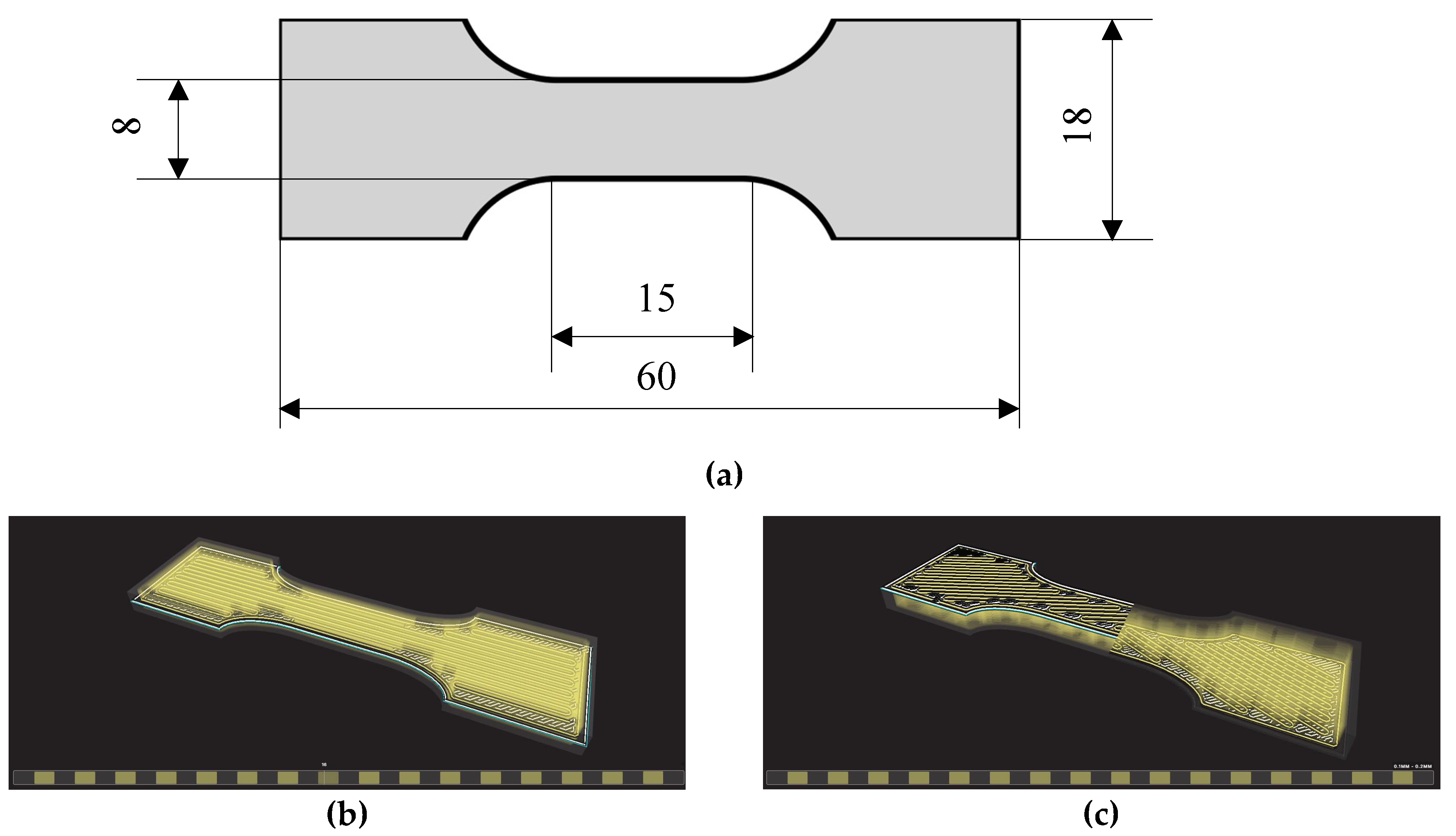
The specimens were prepared for printing by using the dedicated proprietary slicing software Eiger™. The slicer starts by importing the geometry saved in an STL file, then it allows to define the layer sequence. In particular, it allows to define the number and sequence of composite layers and, for each layer, to define the orientation of the fiber (at least for the basic pattern of fiber parallel and aligned in a single direction).
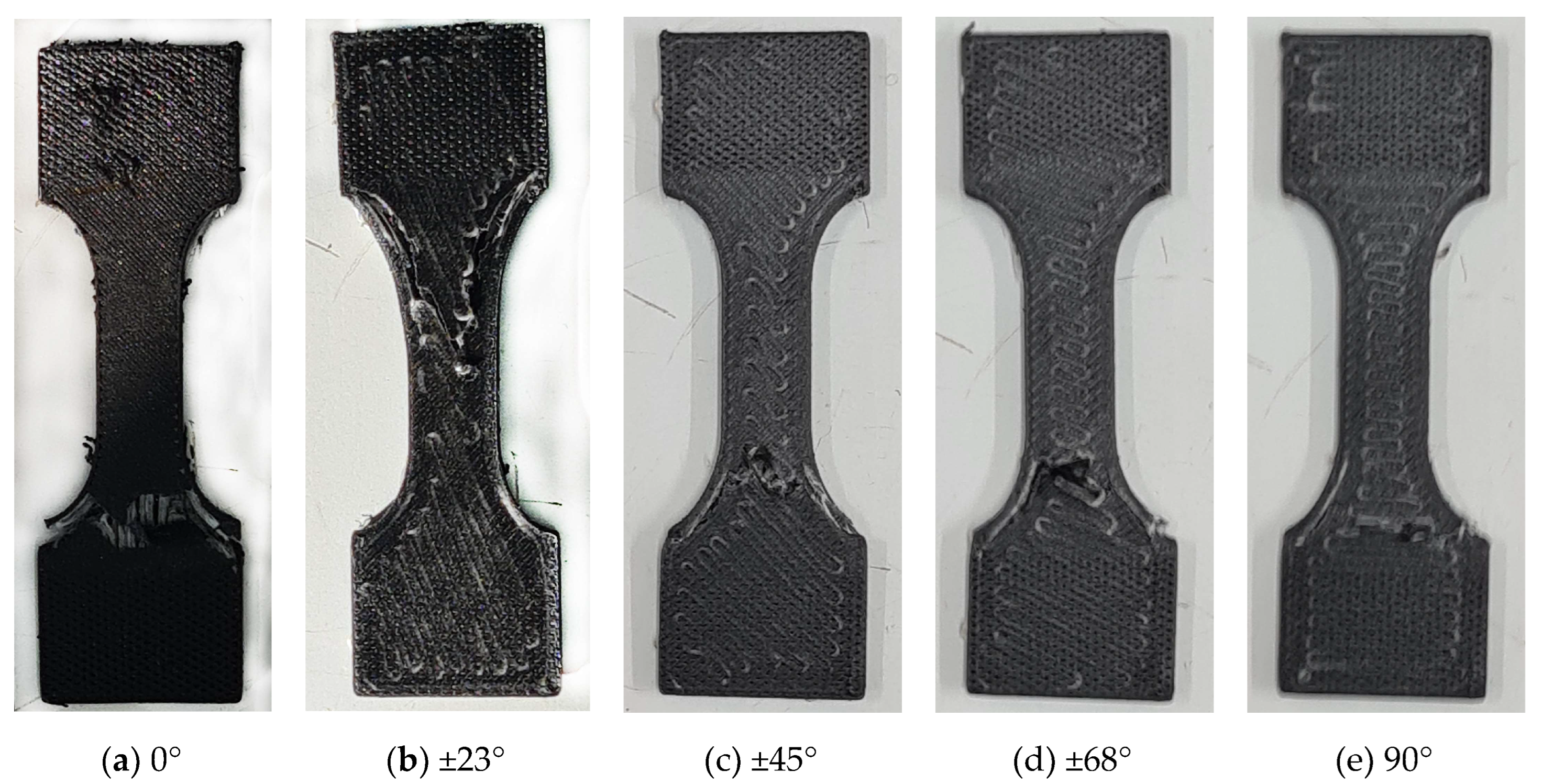
The STL file containing the geometry of the specimens was created with an automated script in OpenSCAD (
https://www.openscad.org) a free software for creating solid CA models with a scripting language. The script allows to generate very quickly and efficiently the geometry of tensile specimens parametrically. In the current work, a standard geometry as in the ISO 527-1 or ASTM D 638 was not used due to restrictions related to the used printer. The classical larger specimens (like ISO 527-2, types 1A or 1B, [
44]) are too bulky, expensive and time consuming, whereas with the smaller specimens (such as ISO 527-2 5A or 5B) it is impossible to obtain a deposition of the fiber compatible with the objectives of the current research (there are technical limitations due the deposition of the fiber into smaller spaces, for example due to the curvature of the filament, as it is evident from
Figure 1).
All the samples were 3D printed by alternating layers of continuous glass fiber (from MarkForged
®) with layers of the polyamide reinforced Onyx™ (also from MarkForged
®; reinforcement is made of carbon microfibers). Basic properties of the two materials are in
Table 1. Recently, some papers were published about fiber-reinforced Onyx. In [
45,
46] carbon-fiber specimens and components were studied; in [
47] Kevlar reinforced Onyx samples were characterized; in [
48] Yun et al. examined the failure of fiberglass reinforced Onyx, showing in particular the influence of the number of layers on the strength in tension.
The fiber deposition was done to obtain a symmetric balanced angle-ply structure according to a [±
θ]
4s layering scheme, being
θ the angle between the longitudinal axial direction of the specimen and the fiber direction. The angle
θ = 0 (
Figure 1(b)) corresponds to the fibers aligned to the longitudinal specimen axis, whereas for
θ = 90° the fibers are perpendicular to that axis (
Figure 1(f)). Symmetry was chosen to avoid unwanted coupling of in-plane and bending behavior; the balanced angle-ply arrangement was chosen to obtain a globally orthotropic structure to avoid coupling of tension with shear behavior. The number of layers was the minimum to obtain a sufficiently homogenized structure.
3. Results
3.1. Experimental Plan
The aim of the current work was to show that the classical lamination theory and the failure criteria used for composite materials can be used to describe the mechanical behavior and strength of layered components obtained by filament deposition. Additionally, these theories can be used to identify the elastic properties of the layers and their strength. These theories and data could be used for the design of components made by filament deposition.
To this aim, samples according to
Figure 1 were manufactured with the Mark Two printer with a number of different orientations as show in
Table 2.
Note that [±
θ]
4s correspond to the following sequence (
Figure 1(b)): [+
θ/−
θ/+
θ/−
θ/+
θ/−
θ/+
θ/−
θ/−
θ/+
θ/−
θ/+
θ/−
θ/+
θ/−
θ/+
θ]. The cases when
θ = 0 or
θ = 90° correspond to unidirectional laminates with fiber aligned or perpendicular to the specimen longitudinal axis respectively.
Other building or lamination parameters were not changed, being not of interest for the current work. In practice, the default, standard, printing parameters of the machine were used.
3.2. Experimental Results
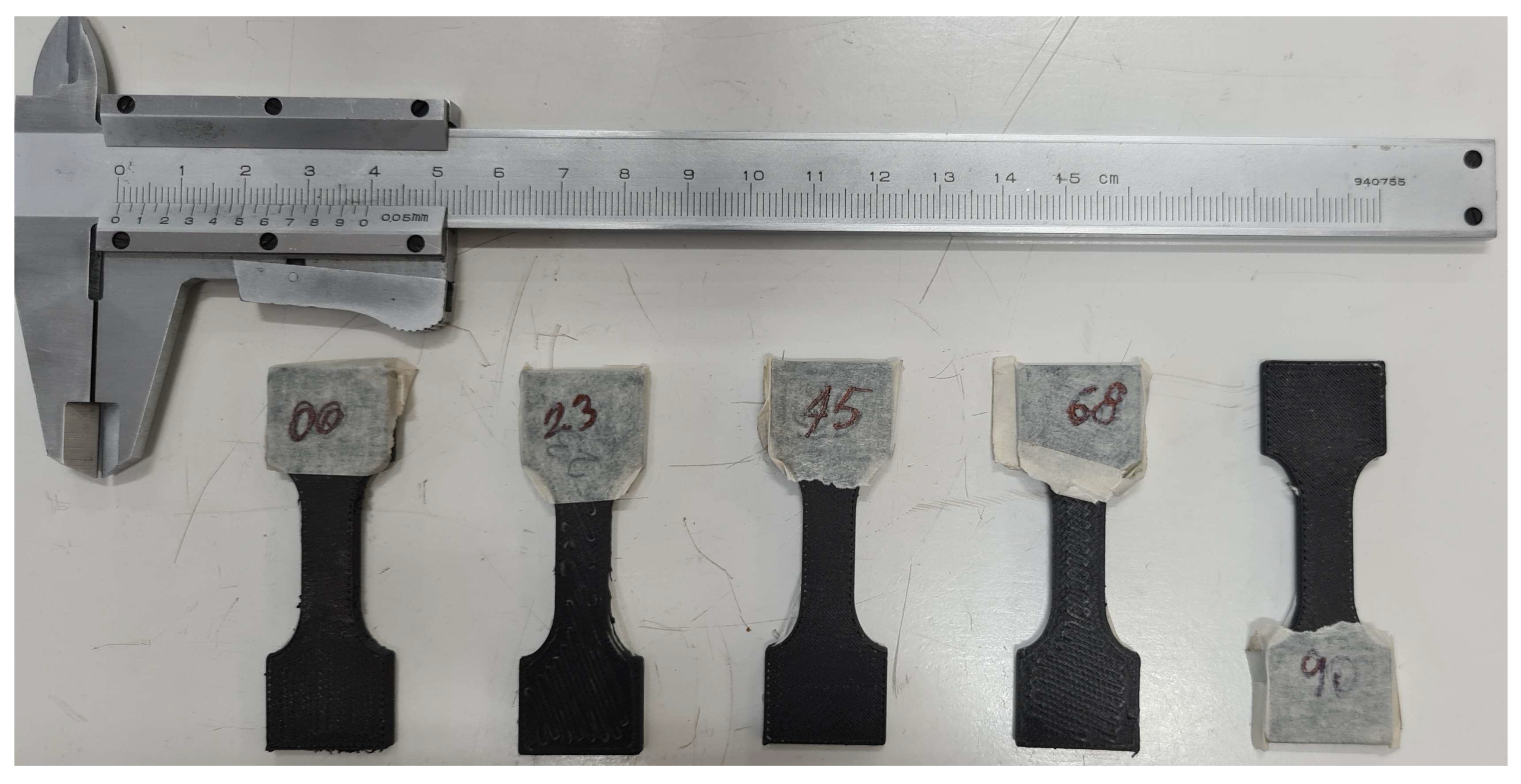
Tensile tests according to ISO 527 were performed with a Zwich Z010 Pro Line universal material testing machine with simple wedge grips. The tests were conducted at a constant speed of 0.5 mm/s until rupture. Force-displacement curves were measured with a 10 kN load cell and a displacement transducer, and recorded by means of the control unit of the machine and the testXpert™ III testing software from Zwick.
In
Figure 3 a curve for each lamination of the tested samples is reported.
In general, the strength of the laminates decreases with the orientation of the fibers increasing from zero (
Figure 3(f)), that is less aligned with the longitudinal direction. The elongation at failure decreases as well, even if more scatter was measured as is quite normal with this result. The tests were sufficiently repeatable (
Figure 3(a)-(e)) in terms of maximum stress, strain, and overall stress-strain behavior. In all cases, the maximum strain remains rather small, always less than 5%: the composite material remains sufficiently brittle so that failure criteria for composite materials are likely to be valid and applicable.
In
Figure 4 some broken samples after the tensile tests are shown. The type of failure is not really obvious, and it is presumably a combination of fiber failure and matrix cracking. This will be confirmed in the following analysis of the failure criteria.
3.2. Identification of the Model Parameters
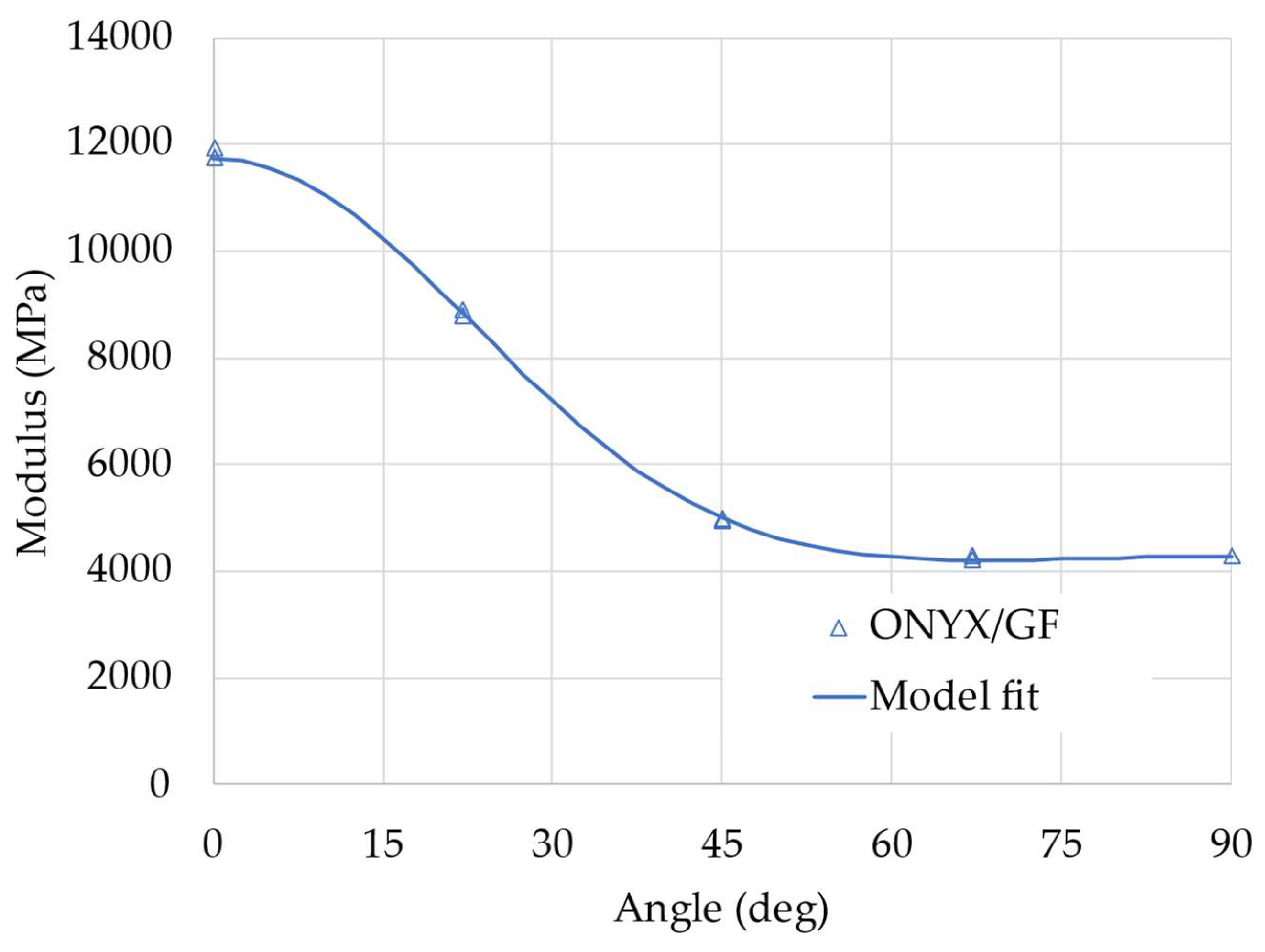
3.2.1. Evaluation of the Elastic Properties
The apparent elastic modulus of the samples with different fiber orientations depends on the elastic properties of the layers and on the angle, following the relations described by Equations (1)-(9) and (10). The layers elastic properties can be then estimated with a non-linear regression analysis by minimizing the square error between the experimental values of the apparent modulus and the value calculated by the model (from equation 10). Results from this analysis are reported in
Figure 5: the curve represents the non-linear fit of the model, showing a very good correlation with the experimental data.
The identified elastic properties of the layers are reported in
Table 3. It is important to compare the measured properties with the values of the elastic moduli of the Onyx and the glass fiber declared by the manufacturer (2.4 GPa and 21 GPa respectively): the layers, made of a combination of the two materials, have elastic moduli along the two directions which are between the elastic moduli of their components. This is an expected result, also justified by using classical micromechanical models for composite materials, such as for example the rule of mixture (RoM). It is not easy in this case to apply such micromechanical models, since the exact layer composition, that is the fraction of matric and fiber, is not known or easily evaluated. Moreover, models like the RoM only give a rough approximation of the moduli which would not be particularly useful.
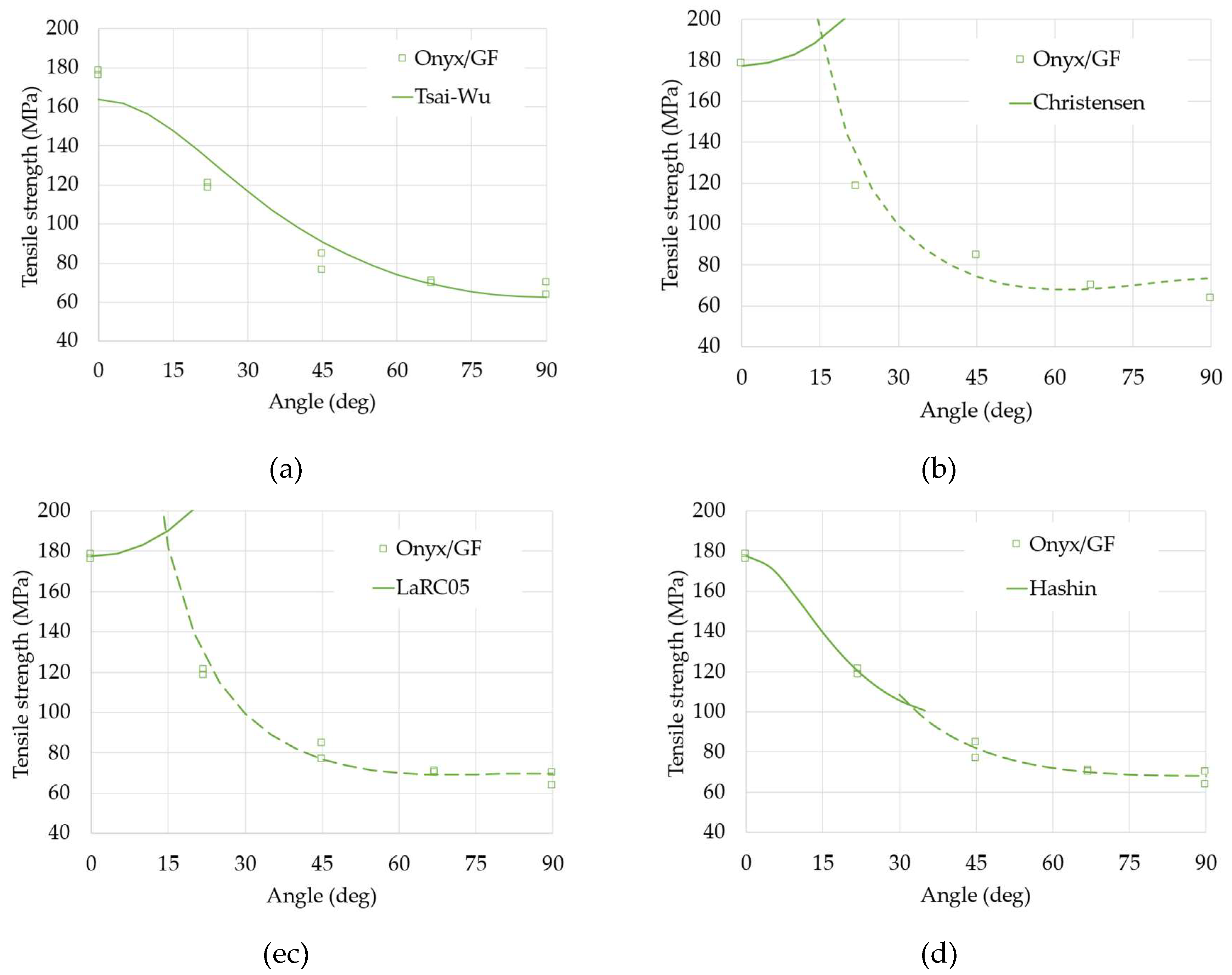
3.2.2. Analysis of the Strength and Identification of a Suitable Failure Model
The strength of the tested samples has been studied to identify the strength properties of the layers with a similar non-linear regression analysis. For the strength, however, an additional problem regards the many applicable failure models, as described in
Section 2.2. The models which have been applied to the experimental data are:
TsaiWu
Christensen
LaRC05
Hashin
The fit of the four models to the experimental data is shown in
Figure 6.
The Tsai-Wu criterion, although relatively simple, seems to give a sufficient approximation of the results especially for the greatest values of orientation: that model does not distinguish between types of failure and, therefore, is not able to fully describe the phenomena involved. On the other end, the failure criteria from Christensen and the LaRC05 model, are also not completely satisfactory; even if both criteria distinguish between types of failure of the fibers (continuous lines) and of the matrix (dashed lines). The better fit, in this case, seems the Hashin criterion (the squared error is minimum for this model). The Hashin criterion too distinguishes between the two types of failure but uses a completely different formulation, energetically based for both cases, that apparently better represents the combination of failure modes observed from the samples tested.
The identified values of the strength parameters are reported in
Table 4. If compared to the strength of the Onyx matrix and glass fiber (40 MPa and 590 MPa, respectively) the identified values seem sufficiently reasonable. Both the strength in the longitudinal and transverse direction of the layers lies between the values of fiber and matrix, as again it is predicted from classical model as the RoM previously mentioned.
5. Conclusions
The mechanical behavior of a composite material obtained by an AM technique was studied in this work. Some papers have been recently published showing applicability of the models used for classical composite materials to structures obtained by means of the FFF technique. However, most papers restrict the analysis to the stiffness and to simple lamination schemes not always accurate nor complete for the analysis (few angles, asymmetric specimens, etc.).
In this paper an innovative type of material for FFF has been tested considering the effect of different laminations, in particular showing the influence of the fiber orientation. To this aim specimens of polyamide (Onix) reinforced with continuous glass fibers were analyzed. The experimental analysis was performed on symmetric angle-ply layered samples. The experimental results showed the strong influence of the orientation angle, due to the high orthotropy of the base material.
The experimental results were then analyzed using the classical lamination theory to estimate the stiffness of the composite material specimen and using several failure criteria to estimate the strength properties. The models fit with good accuracy the experimental results and allow to identify the material properties of the layer. Among the various failure criteria considered, all sufficiently apt to describe the failure of the considered material, the Hashin criterion gives the better fit with very good accuracy for any orientation angle.
The proposed method is promising as a design tool to estimate the mechanical properties of FFF materials for future applications when high stiffness and strength is required in AM components.
Author Contributions
For research articles with several authors, a short paragraph specifying their individual contributions must be provided. The following statements should be used “Conceptualization, M.A. and M.F.; methodology, M.A.; formal analysis, M.F. data curation, M.A.; writing—original draft preparation, M.A.; writing—review and editing, M.A.; visualization, M.A.; supervision, M.F. All authors have read and agreed to the published version of the manuscript.
Funding
This research received no external funding.
Acknowledgments
The authors acknowledge the support of Mr. Francesco Diodà for helping in the specimens’ preparation.
Conflicts of Interest
The authors declare no conflicts of interest.
References
- Pham, D.T.; Gault, R.S. A Comparison of Rapid Prototyping Technologies. Int. J. Mach. Tools Manuf. 1998, 38, 1257–1287. [CrossRef]
- ASTM F2792-12 Standard Terminology for Additive Manufacturing Technologies 2012.
- Crump, S.S. Fast, Precise, Safe Prototypes with FDM. Am. Soc. Mech. Eng. Prod. Eng. Div. PED 1991, 50, 53–60.
- Fico, D.; Rizzo, D.; Casciaro, R.; Corcione, C.E. A Review of Polymer-Based Materials for Fused Filament Fabrication (FFF): Focus on Sustainability and Recycled Materials. Polymers (Basel). 2022, 14. [CrossRef]
- Wang, X.; Jiang, M.; Zhou, Z.; Gou, J.; Hui, D. 3D Printing of Polymer Matrix Composites: A Review and Prospective. Compos. Part B Eng. 2017, 110, 442–458. [CrossRef]
- Daminabo, S.C.; Goel, S.; Grammatikos, S.A.; Nezhad, H.Y.; Thakur, V.K. Fused Deposition Modeling-Based Additive Manufacturing (3D Printing): Techniques for Polymer Material Systems. Mater. Today Chem. 2020, 16, 100248. [CrossRef]
- Christ, J.F.; Aliheidari, N.; Ameli, A.; Pötschke, P. 3D Printed Highly Elastic Strain Sensors of Multiwalled Carbon Nanotube/Thermoplastic Polyurethane Nanocomposites. Mater. Des. 2017, 131, 394–401. [CrossRef]
- Musenich, L.; Berardengo, M.; Avalle, M.; Haj-Ali, R.; Sharabi, M.; Libonati, F. Anisotropic Mechanical and Sensing Properties of Carbon Black-Polylactic Acid Nanocomposites Produced by Fused Filament Fabrication. Smart Mater. Struct. 2024, 33. [CrossRef]
- Gao, G.; Xu, F.; Xu, J.; Tang, G.; Liu, Z. A Survey of the Influence of Process Parameters on Mechanical Properties of Fused Deposition Modeling Parts. Micromachines 2022, 13, 1–28. [CrossRef]
- Lanzotti, A.; Grasso, M.; Staiano, G.; Martorelli, M. The Impact of Process Parameters on Mechanical Properties of Parts Fabricated in PLA with an Open-Source 3-D Printer. Rapid Prototyp. J. 2015, 21, 604–617. [CrossRef]
- Gonabadi, H.; Yadav, A.; Bull, S.J. The Effect of Processing Parameters on the Mechanical Characteristics of PLA Produced by a 3D FFF Printer. Int. J. Adv. Manuf. Technol. 2020, 111, 695–709. [CrossRef]
- Vǎlean, C.; Marşavina, L.; Mǎrghitaşl, M.; Linul, E.; Razavi, N.; Berto, F. Effect of Manufacturing Parameters on Tensile Properties of FDM Printed Specimens. Procedia Struct. Integr. 2020, 26, 313–320. [CrossRef]
- Ahn, S.H.; Montero, M.; Odell, D.; Roundy, S.; Wright, P.K. Anisotropic Material Properties of Fused Deposition Modeling ABS. Rapid Prototyp. J. 2002, 8, 248–257. [CrossRef]
- Wu, W.; Geng, P.; Li, G.; Zhao, D.; Zhang, H.; Zhao, J. Influence of Layer Thickness and Raster Angle on the Mechanical Properties of 3D-Printed PEEK and a Comparative Mechanical Study between PEEK and ABS. Materials (Basel). 2015, 8, 5834–5846. [CrossRef]
- Croccolo, D.; De Agostinis, M.; Olmi, G. Experimental Characterization and Analytical Modelling of the Mechanical Behaviour of Fused Deposition Processed Parts Made of ABS-M30. Comput. Mater. Sci. 2013, 79, 506–518. [CrossRef]
- Cantrell, J.T.; Rohde, S.; Damiani, D.; Gurnani, R.; DiSandro, L.; Anton, J.; Young, A.; Jerez, A.; Steinbach, D.; Kroese, C.; et al. Experimental Characterization of the Mechanical Properties of 3D-Printed ABS and Polycarbonate Parts. Rapid Prototyp. J. 2017, 23, 811–824. [CrossRef]
- Hameed, A.Z.; Aravind Raj, S.; Kandasamy, J.; Shahzad, M.A.; Baghdadi, M.A. 3D Printing Parameter Optimization Using Taguchi Approach to Examine Acrylonitrile Styrene Acrylate (ASA) Mechanical Properties. Polymers (Basel). 2022, 14. [CrossRef]
- Sun, Q.; Rizvi, G.M.; Bellehumeur, C.T.; Gu, P. Effect of Processing Conditions on the Bonding Quality of FDM Polymer Filaments. Rapid Prototyp. J. 2008, 14, 72–80. [CrossRef]
- Syrlybayev, D.; Zharylkassyn, B.; Seisekulova, A.; Akhmetov, M.; Perveen, A.; Talamona, D. Optimisation of Strength Properties of FDM Printed Parts — A. Polymers (Basel). 2021, 13, 1–35.
- Somireddy, M.; Singh, C. V.; Czekanski, A. Analysis of the Material Behavior of 3D Printed Laminates Via FFF. Exp. Mech. 2019, 59, 871–881. [CrossRef]
- Alaimo, G.; Marconi, S.; Costato, L.; Auricchio, F. Influence of Meso-Structure and Chemical Composition on FDM 3D-Printed Parts. Compos. Part B Eng. 2017, 113, 371–380. [CrossRef]
- Rajpurohit, S.R.; Dave, H.K.; Rajurkar, K.P. Prediction of Tensile Strength of Fused Deposition Modeling (FDM) Printed PLA Using Classic Laminate Theory. Eng. Solid Mech. 2022, 10, 13–24. [CrossRef]
- Dai, S.; Deng, Z.C.; Yu, Y.J.; Zhang, K.; Wang, S.H.; Ye, J. Orthotropic Elastic Behaviors and Yield Strength of Fused Deposition Modeling Materials: Theory and Experiments. Polym. Test. 2020, 87, 106520. [CrossRef]
- YİLMAZ, C.; ALİ, H.Q.; YILDIZ, M. Klasik Laminasyon Teorisinin Üç Boyutlu Yazıcı Ile Eriyik Yığma Modelleme Yöntemi Kullanılarak Üretilmiş Plastiklere Uygulanması ve Tam Alanlı Yüzey Gerinim Haritalanması. Afyon Kocatepe Univ. J. Sci. Eng. 2022, 22, 342–352. [CrossRef]
- Avalle, M.; Monti, M.; Frascio, M. Modeling the Strength of Laminated Parts Made by Fused Filament Fabrication Additive Manufacturing. Proc. Inst. Mech. Eng. Part C J. Mech. Eng. Sci. 2023. [CrossRef]
- Jones, R.M. Mechanics of Composite Materials.; Taylor and Francis: Philadelphia, PA, 1984; ISBN 0938994247.
- Halpin, J.C. Primer on Composite Materials Analysis, Second Edition (Revised); 2nd editio.; Routledge: Lancaster, PA, 2017; ISBN 9780203742235.
- Nettles, A.T. Basic Mechanics of Laminated Composite Plates. NASA Ref. pulication 1994, 107.
- Casavola, C.; Cazzato, A.; Moramarco, V.; Pappalettere, C. Orthotropic Mechanical Properties of Fused Deposition Modelling Parts Described by Classical Laminate Theory. Mater. Des. 2016, 90, 453–458. [CrossRef]
- Nasirov, A.; Hasanov, S.; Fidan, I. Prediction of Mechanical Properties of Fused Deposition Modeling Made Parts Using Multiscale Modeling and Classical Laminate Theory. Solid Free. Fabr. 2019 Proc. 30th Annu. Int. Solid Free. Fabr. Symp. - An Addit. Manuf. Conf. SFF 2019 2019, 1373–1382.
- Hill, R. Theory of Mechanical Properties of Fibre-Strengthened Materials—III. Self-Consistent Model. J. Mech. Phys. Solids 1965, 13, 189–198. [CrossRef]
- Tsai, S.W. Strength Theories of Filamentary Structures, in Fundamental Aspects of Fiber Reinforced Plastic Composites. In Proceedings of the Fundamental Aspects of Fiber Reinforced Plastic Composites; Schwartz, R.T., Schwartz, H.S., Eds.; Interscience Publishers, 1968; p. 284.
- Tsai, S.W.; Wu, E.M. A General Theory of Strength for Anisotropic Materials; 1972;
- Tsai, S.W.; Wu, E.M. A General Theory of Strength for Anisotropic Materials. J. Compos. Mater. 1971, 5, 58–80. [CrossRef]
- ISO 527-1:2019 Plastics — Determination of Tensile Properties Part 1: General Principles 2019.
- ASTM D638-14 Standard Test Method for Tensile Properties of Plastics 2014.
- Hill, R. A Theory of the Yielding and Plastic Flow of Anisotropic Metals. Proc. R. Soc. London. Ser. A. Math. Phys. Sci. 1948, 193, 281–297. [CrossRef]
- Azzi, V.D.; Tsai, S.W. Anisotropic Strength of Composites - Investigation Aimed at Developing a Theory Applicable to Laminated as Well as Unidirectional Composites, Employing Simple Material Properties Derived from Unidirectional Specimens Alone. Exp. Mech. 1965, 5, 283–288. [CrossRef]
- Hashin, Z.; Rotem, A. A Fatigue Failure Criterion for Fiber Reinforced Materials. J. Compos. Mater. 1973, 7, 448–464. [CrossRef]
- Hashin, Z. Failure Criteria for Unidirectional Fiber Composites. J. Appl. Mech. Trans. ASME 1980, 47, 329–334. [CrossRef]
- Christensen, R.M. Completion and Closure on Failure Criteria for Unidirectional Fiber Composite Materials. J. Appl. Mech. 2014, 81, 1–6. [CrossRef]
- Pinho, S.T.; Dávila, C.G.; Camanho, P.P.; Iannucci, L.; Robinson, P. Failure Models and Criteria for FRP Under In-Plane or Three-Dimensional Stress States Including Shear Non-Linearity. Nasa/Tm-2005-213530 2005, 68.
- Pinho, S.T.; Darvizeh, R.; Robinson, P.; Schuecker, C.; Camanho, P.P. Material and Structural Response of Polymer-Matrix Fibre-Reinforced Composites. J. Compos. Mater. 2012, 46, 2313–2341. [CrossRef]
- ISO 527-2:2012 Plastics — Determination of Tensile Properties Part 2: Test Conditions for Moulding and Extrusion Plastics 2012.
- Vedrtnam, A.; Ghabezi, P.; Gunwant, D.; Jiang, Y.; Sam-Daliri, O.; Harrison, N.; Goggins, J.; Finnegan, W. Mechanical Performance of 3D-Printed Continuous Fibre Onyx Composites for Drone Applications: An Experimental and Numerical Analysis. Compos. Part C Open Access 2023, 12, 100418. [CrossRef]
- Ghebretinsae, F.; Mikkelsen, O.; Akessa, A.D. Strength Analysis of 3D Printed Carbon Fibre Reinforced Thermoplastic Using Experimental and Numerical Methods. IOP Conf. Ser. Mater. Sci. Eng. 2019, 700. [CrossRef]
- Vaithiyanathan, A.; Farhan, H.; Raja, D.E.; Singh, S.P.; Sonar, T. Microstructural Characteristics and Mechanical Properties of 3D Printed Kevlar Fibre Reinforced Onyx Composite. Mater. Test. 2024, 1–9. [CrossRef]
- Yun, J.H.; Yoon, G.W.; Jeon, Y.J.; Kang, M.S. Evaluation of the Properties of 3D-Printed Onyx–Fiberglass Composites. Materials (Basel). 2024, 17. [CrossRef]
|
Disclaimer/Publisher’s Note: The statements, opinions and data contained in all publications are solely those of the individual author(s) and contributor(s) and not of MDPI and/or the editor(s). MDPI and/or the editor(s) disclaim responsibility for any injury to people or property resulting from any ideas, methods, instructions or products referred to in the content. |
© 2025 by the authors. Licensee MDPI, Basel, Switzerland. This article is an open access article distributed under the terms and conditions of the Creative Commons Attribution (CC BY) license (http://creativecommons.org/licenses/by/4.0/).