1. Introduction
The fluxgate sensor is a magnetic field sensor used to measure magnetic field strength. It is characterized by its high sensitivity, high accuracy, high resolution, simple and compact structures, and low noise[
1,
2,
3,
4,
5,
6,
7,
8,
9], making it ideal for applications that require accurate and reliable magnetic field measurements. The fluxgate sensor technology originated in the 1930s and, it has been widely applied in various fields, including near-Earth magnetic field measurement, interstellar magnetic field measurement, aerospace navigation, and biomedical applications [
10,
11,
12,
13,
14]. Today, it is extensively used in the measurement of near-Earth space background magnetic fields, interstellar magnetic fields, aircraft and vehicle navigation, and biomedical fields. Butta et al. studied the relationship between the noise of orthogonal fluxgate sensors and the materials used in the magnetic core. The noise in the fundamental mode of the orthogonal fluxgate sensor is primarily attributed to Barkhausen noise, which arises from the motion of domain walls in the alloy wires that make up the magnetic sensor core [
15]. Janosek et al. developed the fundamental mode orthogonal fluxgate magnetometer with the lowest noise, which provides theoretical support for the realization of low-noise magnetometers[
16]. Paperno et al. has been found that a sufficiently high DC bias can practically completely suppress the magnetic noise generated in the fluxgate core by the AC-bias field[
17]. Zhang developed a passive filter circuit to mitigate the noise related to the fundamental frequency from the source, thereby ensuring stable operation and optimizing the system's performance[
18].
Meanwhile, sensitivity is also one of the key performance indicators of fluxgate magnetic sensors. Ripka, P. tuned the current-output fluxgate by using a series capacitor, which improved the sensor's sensitivity with a lower number of turns in the pickup coil. The signal-to-feedthrough ratio was increased by a factor of 5[
19]. Priftis, P. introduced a novel fluxgate magnetometer design that utilizes a sinusoidal signal for exciting the magnetic core, resulting in enhanced sensitivity and reduced power consumption[
20]. Dezuari developed an affordable and straightforward trilayer printed circuit board (PCB)-based technology, demonstrating a relatively high sensitivity of Is V/T at an excitation current frequency of 10 wiz[
21].
From the above studies, it is evident that current research on fluxgate technology mainly focuses on optimizing the magnetic core parameters and the overall structure. In contrast, research on the sensing coils has been relatively limited. This study aims to effectively suppress the EMF caused by the transformer effect using a dual-core fluxgate structure. This approach is intended to improve the magnetic field measurement sensitivity and reducing noise of the fluxgate sensor. To this end, we constructed a model of the fluxgate probe and its excitation external circuit on the Maxwell software platform. We then systematically investigated the effects of sensing coil parameters on the induced EMF of the fluxgate sensor.
2. Working Principle of the Dual-Core Fluxgate
The fluxgate sensor utilizes the nonlinear relationship between magnetic induction intensity and magnetic field strength. This relationship is observed under the alternating magnetic field saturation excitation of a high permeability magnetic core, allowing the sensor to measure weak magnetic fields. This physical phenomenon can be considered as a "gate" that modulates the magnetic flux, thereby generating an induced EMF. This process enables the indirect measurement of the magnetic field generated by electric currents, thereby facilitating the detection of the currents.
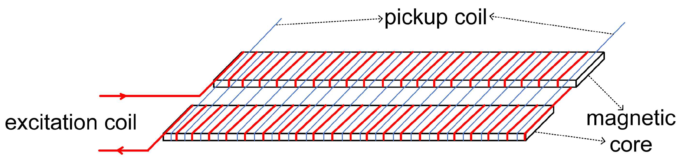
The core component of a fluxgate sensor is the fluxgate probe, which mainly consists of the magnetic core, excitation coil, and sensing coil[
22]. Its operating principle is based on a periodically varying current that generates an alternating magnetic field around the magnetic core, causing the core to enter deep saturation. At this point, the magnetization process of the core undergoes significant changes, generating an induced EMF that is related to the external magnetic field strength[
23]. By measuring this induced signal, the otherwise difficult-to-measure external magnetic field information can be converted into a voltage signal. After further processing by the circuitry, this voltage signal is converted into a value proportional to the measured magnetic field strength[
24]. Finally, by using a proportional coefficient, the intensity of the environmental magnetic field can be precisely calculated, enabling accurate magnetic field detection.
The structure of the dual-core fluxgate probe is shown in
Figure 1.
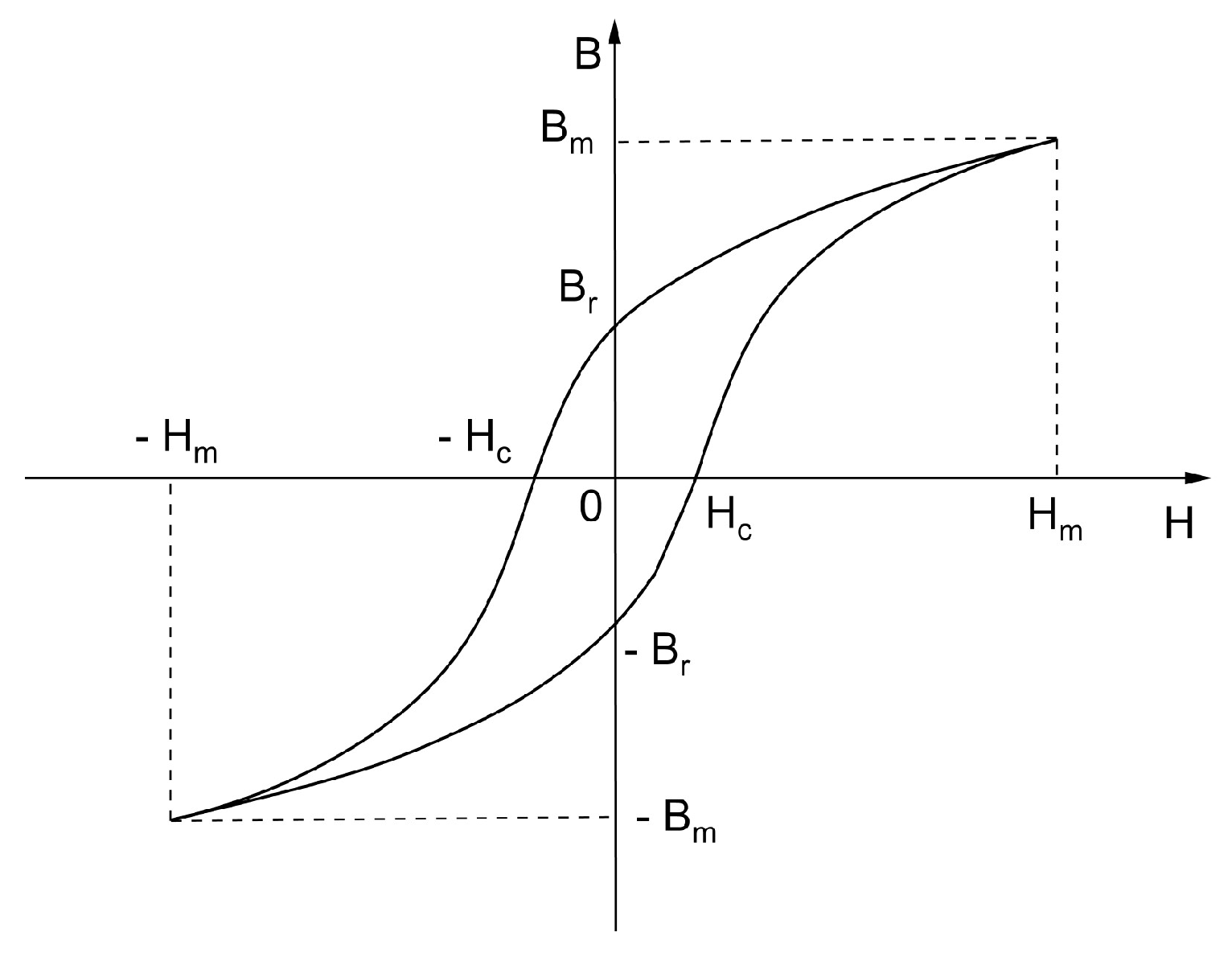
In the magnetization process of magnetic materials, the relationship between magnetic induction (B) and magnetic field strength (H) is nonlinear, exhibiting a typical S-shaped curve. This phenomenon is known as hysteresis. Specifically, it manifests as a closed loop in the magnetization curve, commonly referred to as the hysteresis loop, as shown in
Figure 2.
The hysteresis loop is typically plotted on a coordinate axis of magnetic induction (B) versus magnetic field strength (H). It reflects the behavior of magnetic materials during the processes of complete magnetization and demagnetization. The diagram illustrates the hysteresis loop of a typical ferromagnetic material.
In the experiment, a periodically varying alternating current is passed through the excitation coil, generating an alternating magnetic field. Under the combined influence of this alternating magnetic field and the external environmental magnetic field, the magnetic induction in the upper part of the magnetic core can be written as
where
represents the strength of the environmental magnetic field,
is the excitation magnetic field generated by the excitation coil, and
is the magnetic permeability of the magnetic core. Similarly, the magnetic induction in the lower part of the magnetic core can be written as
Based on the magnetization characteristics of soft magnetic materials, the B-H curve can be approximately described by the following relationship.
In the equation,
and
are specific coefficients. By performing a Maclaurin series expansion of equation (3) and neglecting terms of third order and higher, the following expression is obtained.
Where
,
. Substituting equations (1) and (2) into equation (4), the magnetic flux of the induction coil can be written as
In the equation,
represents the number of turns of the induction coil, and
is the cross-sectional area of the induction coil. According to Faraday's law of electromagnetic induction, the induced voltage generated by the induction coil can be written as
From equation (6), it can be seen that the frequency of the induced voltage is twice that of the excitation current. The amplitude is directly proportional to the strength of the ambient magnetic field. It increases linearly with the number of turns of the induction coil, its cross-sectional area, as well as the amplitude and frequency of the excitation magnetic field.
3. Methods
3.1. Fluxgate Probe Model
3.1.1. Core Simulation Model
Under the influence of an excitation magnetic field, the magnetic core needs to reach a deep saturation state. By measuring the resulting fluxgate signal, the external magnetic field information, which is difficult to measure directly, can be converted into a measurable voltage signal. Therefore, in the design of the magnetic core, facilitating its entry into saturation is key to improving the performance of the fluxgate sensor. The material of the magnetic core directly determines its characteristics. When a high permeability material is chosen, it can significantly reduce the excitation voltage required for the core to reach saturation flux density, thereby lowering the power consumption of the magnetic sensor. Furthermore, during the operation of the fluxgate sensor, the magnetic core is influenced by the alternating excitation magnetic field, generating induced electromotive forces (EMFs). These EMFs give rise to eddy currents, which can affect the measurement accuracy of the fluxgate sensor. To minimize the impact of eddy current losses, materials with relatively high electrical resistivity should be selected for the core to reduce this effect.
As this study uses a dual-core fluxgate sensor, stringent requirements must be placed on the alignment of the core structures. Additionally, when the magnetic core is magnetized, the high magnetostrictive properties cause dimensional changes in the core, which can induce interference. Thus, low magnetostrictive properties are also a crucial parameter when selecting materials for the fluxgate sensor[
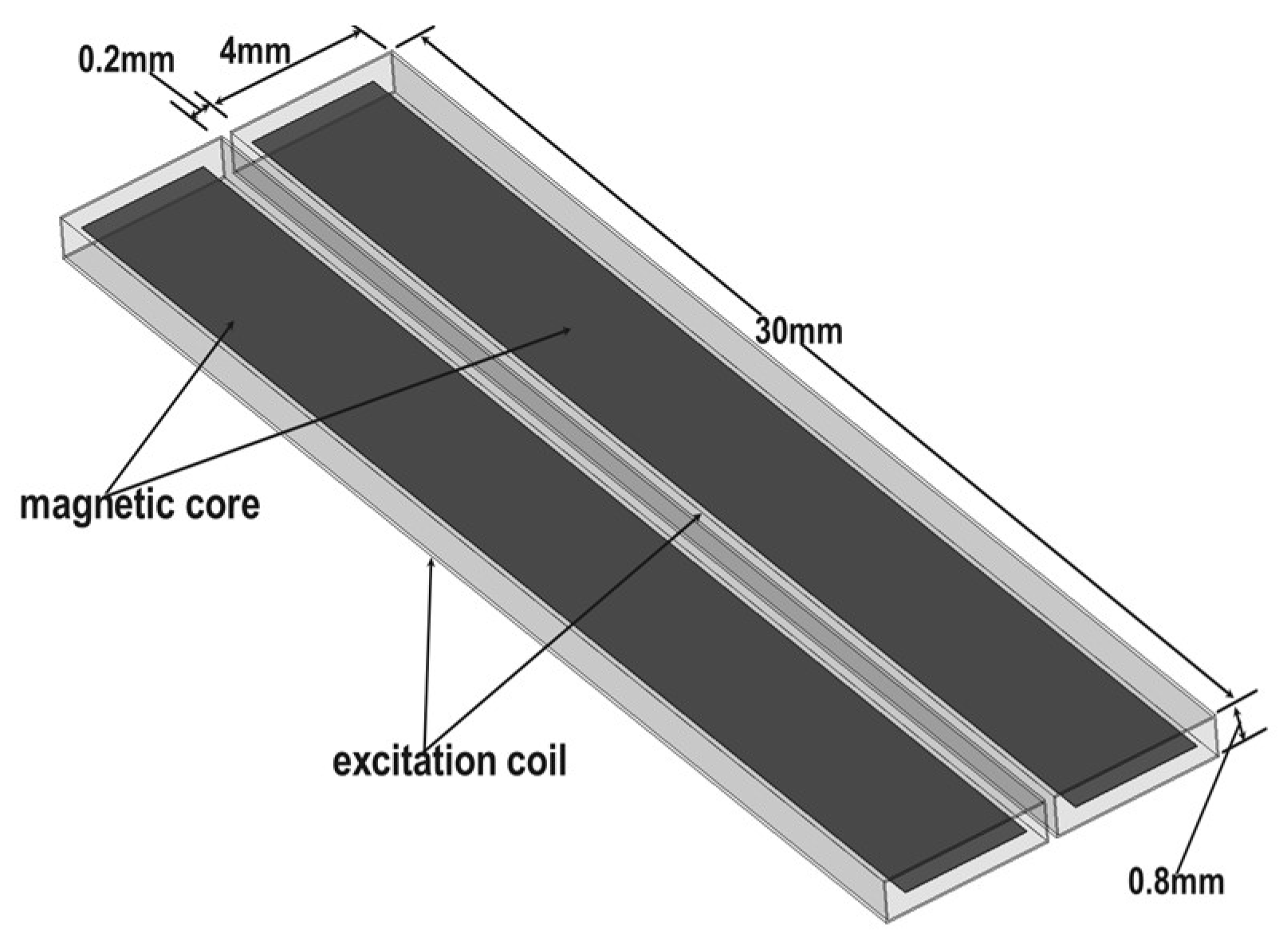
26]. Considering practical constraints, the core material selected is Permalloy, which has a relatively low saturation flux density and high permeability. In terms of structural design, considering the size limitations of existing fluxgate sensors, the simulation model of the magnetic core is designed to more accurately reflect real-world conditions. The core is modeled as two identical thin strips, each with a length of 30 mm, width of 3 mm, and thickness of h = 0.02 mm. These two magnetic cores are placed parallel on the same plane. It is important to note that, since each excitation coil must be wound around each core, the gap between the two cores must be greater than twice the coil diameter. The final gap distance is determined to be 1.2 mm, as shown in
Figure 3.
3.1.2. Excitation Coil Simulation Model
Maxwell software provides a built-in feature that allows the direct assignment of coil turns and windings to a model. By designing a cylindrical model around the magnetic core and setting appropriate parameters, the excitation coils can be effectively simulated. As shown in
Figure 4, two excitation coils are wound around the magnetic core. The dimensions of the core are as follows: length of 30 mm, width of 3.9 mm, and height of 0.7 mm. The coil diameter is 0.1 mm, and the distance between the two coils is 0.2 mm. Each coil consists of 700 turns. Due to its excellent conductivity and low resistivity, copper is chosen as the material for the excitation coils. Copper’s superior electrical properties result in lower energy losses and reduced heat generation compared to other metal conductors when transmitting current. Therefore, copper wire is selected for the excitation coil material in this study.
3.1.3. Pickup Coil Simulation Model
In order to investigate the influence of different parameters of the induction coil on the EMF, this study first designs a magnetic induction coil model, and then conducts research by varying parameters related to the induced EMF.
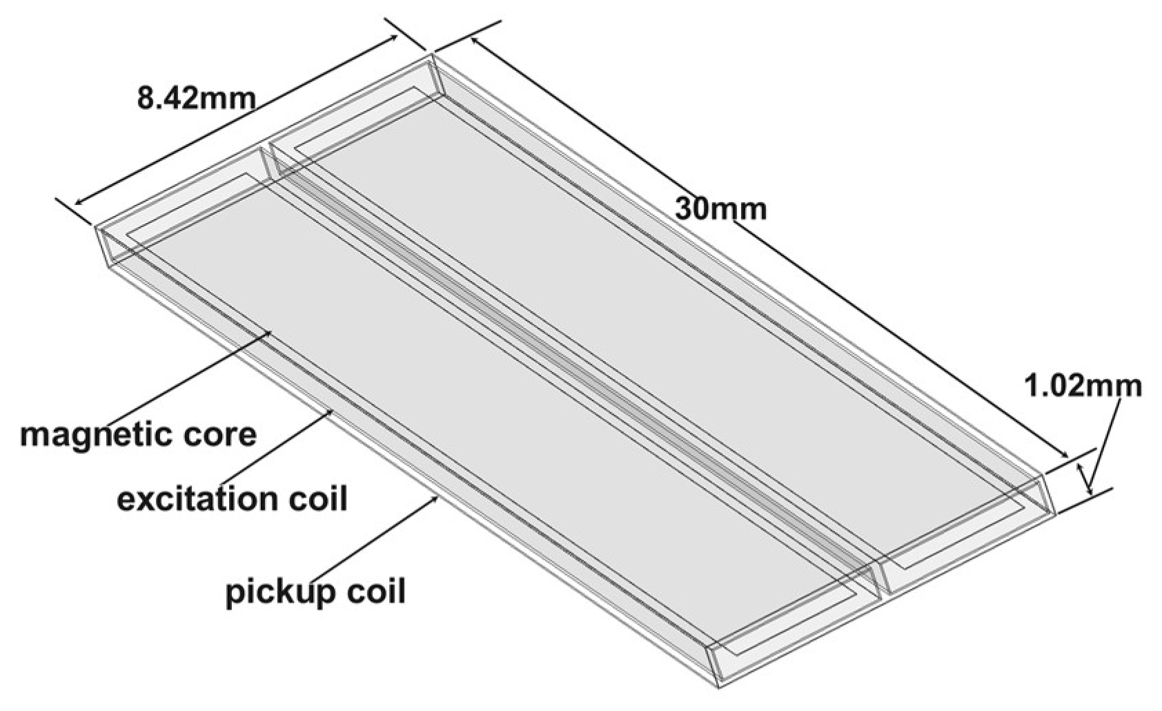
Since the induction coil needs to detect both the ambient magnetic field and the alternating magnetic field generated by the two excitation coils, it is wound around the periphery of the excitation coils. The induction coil is made from the same material and has the same shape as the excitation coils. As shown in
Figure 5, the coil dimensions are 30 mm in length, 8.42 mm in width, and 1.02 mm in height, with a wire diameter of 0.02 mm. Theoretically, according to Equation (6), the induced EMF output of the induction coil is proportional to the number of turns. As the number of turns increases, the induced EMF generated by the same ambient magnetic field becomes larger. As a result, the sensitivity of the magnetic fluxgate sensor is higher. However, this conclusion neglects the internal resistance of the pickup coil itself. In practice, based on the definitions of resistance and inductance:
represents the resistivity of the copper wire, denotes the length of the copper wire, and is the cross-sectional area of a single copper wire. is the number of turns of the excitation coil, is the magnetic flux, and is the excitation current. It can be seen that when the number of turns of the induction coil increases, the inductance also increases. Additionally, as the length of the coil increases, the internal resistance of the coil increases as well. The increase in both inductance and resistance will further affect the quality of the output signal. Therefore, to minimize interference, it is necessary to choose an appropriate number of coil turns. In this study, the base number of turns is chosen as 1200, and the coil pitch is 0.005 mm.
3.1.4. Environmental Magnetic Field Simulation Model
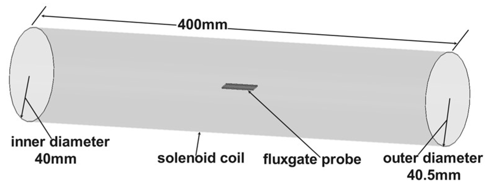
The geomagnetic field ranges from 50,000 nT to 60,000 nT. To simulate the environmental magnetic field, a solenoid coil model was designed in this study. This model ensures that no other factors interfere with the magnetic probe. This model has a structure significantly larger than the fluxgate probe, as shown in
Figure 6. The solenoid is 400 mm in length, with an inner diameter of 40 mm and an outer diameter of 40.5 mm. It is made of copper wire and consists of 400 turns. A constant current of 45 mA is applied to generate a steady-state magnetic field of 55,000 nT within the solenoid.
3.2. Design of External Circuit Excitation Model
Since the fluxgate must operate under appropriate excitation magnetic field conditions, the shape and structure of the excitation coil must first be determined. After that, the excitation circuit needs to be constructed to ensure that the coil, powered by alternating current, successfully magnetizes the magnetic core to a periodic saturation state.
To integrate the fluxgate sensor as a whole on a simulation platform, this study employs the Maxwell Circuit Design tool. This tool, which is included with Maxwell software, is used to design the external circuit of the excitation coil. To reflect real-world conditions as accurately as possible, the equivalent resistance of the inductance needs to be calculated. The resistivity of the copper wire is 0.0172 μΩ·m, and the length l can be written as
represents the number of turns of the coil,
the coil width,
the coil height, and
the radius of the copper wire. From equation (9), the coil length l is calculated to be 6720 mm, with a cross-sectional area of approximately 0.00785 mm². Using equation (7), the equivalent resistance of the coil is estimated to be around 30 Ω. Based on this, an RLC series circuit model, as shown in
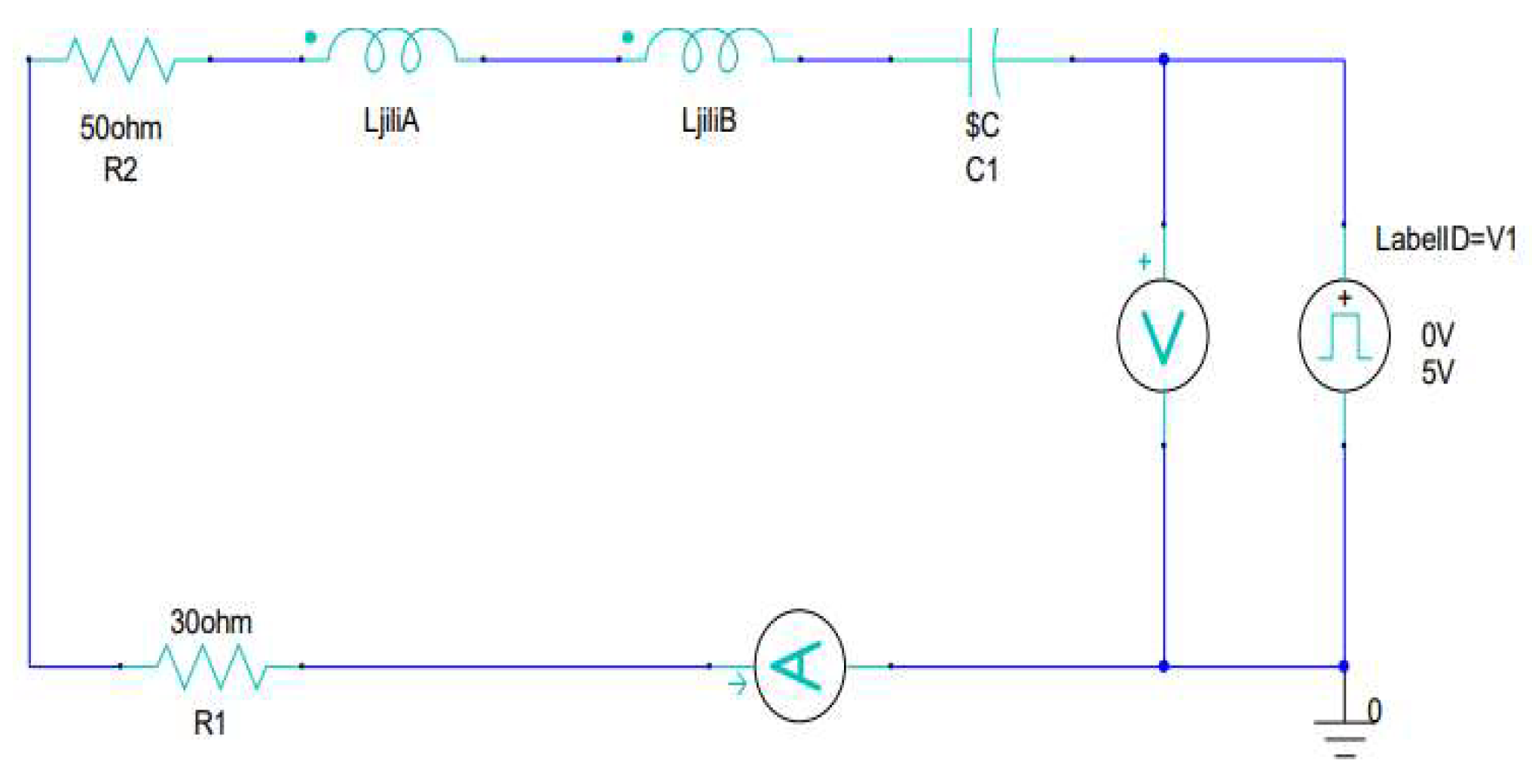
Figure 7, is established.
In the circuit diagram, R1 represents the equivalent resistance of the excitation coil. The excitation source V1 is configured as a square wave with a voltage range of 0–5V, a duty cycle of 50%, and a frequency of 15.625 kHz. A voltmeter is connected in parallel to monitor the operation of the excitation source during the subsequent simulation. LjiliA and LjiliB represent the two sets of excitation coils in the magnetic probe simulation model. R2 is the current-limiting resistor, which prevents the pickup coils from being damaged by excessive current during operation. C1 is the circuit matching capacitor, and by adjusting C1 to different values, the excitation current is measured under various conditions. It was ultimately determined that the sensor performance is optimal when C1 has a capacitance of 20 nF.
Finally, an ammeter is connected in series with the entire circuit to observe the variation of the excitation current during the operation of the magnetic fluxgate. During circuit operation, the square wave signal is input into the RLC series circuit, which filters the input signal. The inductor generates impedance to the high-frequency components of the signal, while the capacitor generates impedance to the low-frequency components. This combination attenuates the high-frequency harmonic components of the square wave signal and smooths the output signal. The specific process is as follows: during the rising or falling edges of the square wave, the inductor prevents rapid changes in current, resulting in a smoother current rise. Meanwhile, the capacitor begins charging or discharging, helping to reduce voltage fluctuations and gradually stabilize the output voltage.
Under the condition that the inductor and power supply parameters are fixed, the selection of the capacitor becomes crucial for the proper functioning of the excitation circuit. If the capacitance is too large, it will cause excessive discharge time, leading to current jumps during the rising edge of the square wave. If the capacitance is too small, the discharge time will be too short, causing the circuit to oscillate. Therefore, ideally, the capacitor should discharge exactly when the power supply level transitions, ensuring that the excitation current reaches zero at the transition. After simulation and tuning, it was determined that the optimal matching capacitance for C1 is 20 nF.
4. Simulation and Result
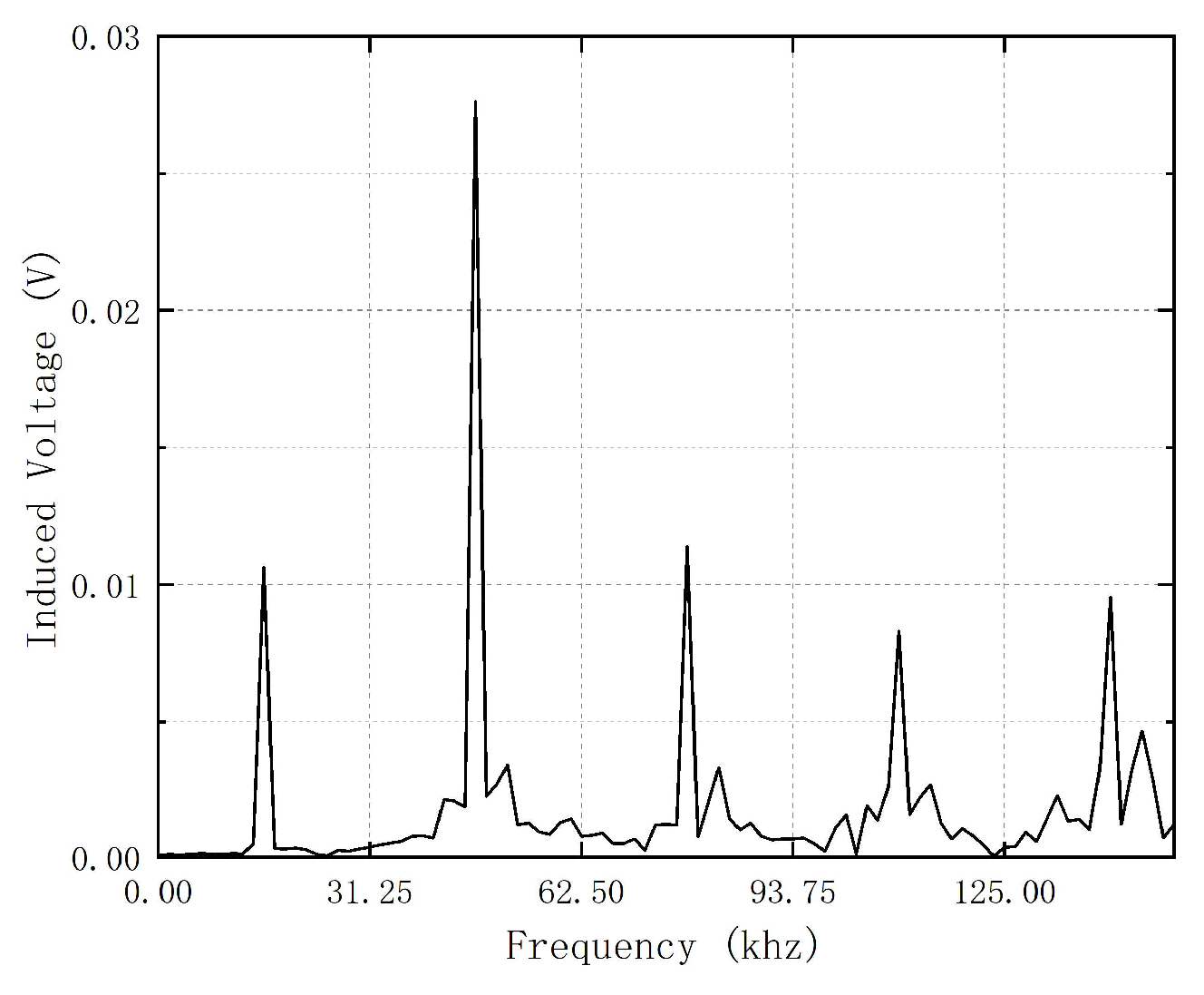
From equation (6), it can be observed that the waveform of the EMF ideally contains only the second harmonic of the excitation waveform. However, in practice, when the fluxgate sensor measures the magnetic field, it is influenced by factors such as temperature and inherent defects in the components. Additionally, asymmetries between the two devices can also affect the measurement. These factors inevitably generate noise, resulting in the contamination of the waveform with spurious components. To filter out these spurious components, this study utilizes the built-in "Perform FFT on Report" function of Maxwell software. This function applies a Fast Fourier Transform (FFT) to the simulation results of the fluxgate. By doing so, the second harmonic at 31.25 kHz can be identified in the frequency domain, allowing for the accurate determination of the second harmonic voltage. It is important to note that the stop time must be set to 640 μs, and the step size should be 2 μs. If the step size is too large, the simulation results will lack sufficient accuracy. Additionally, if the stop time is set to other values, the corresponding induced voltage of the second harmonic will not be obtained.
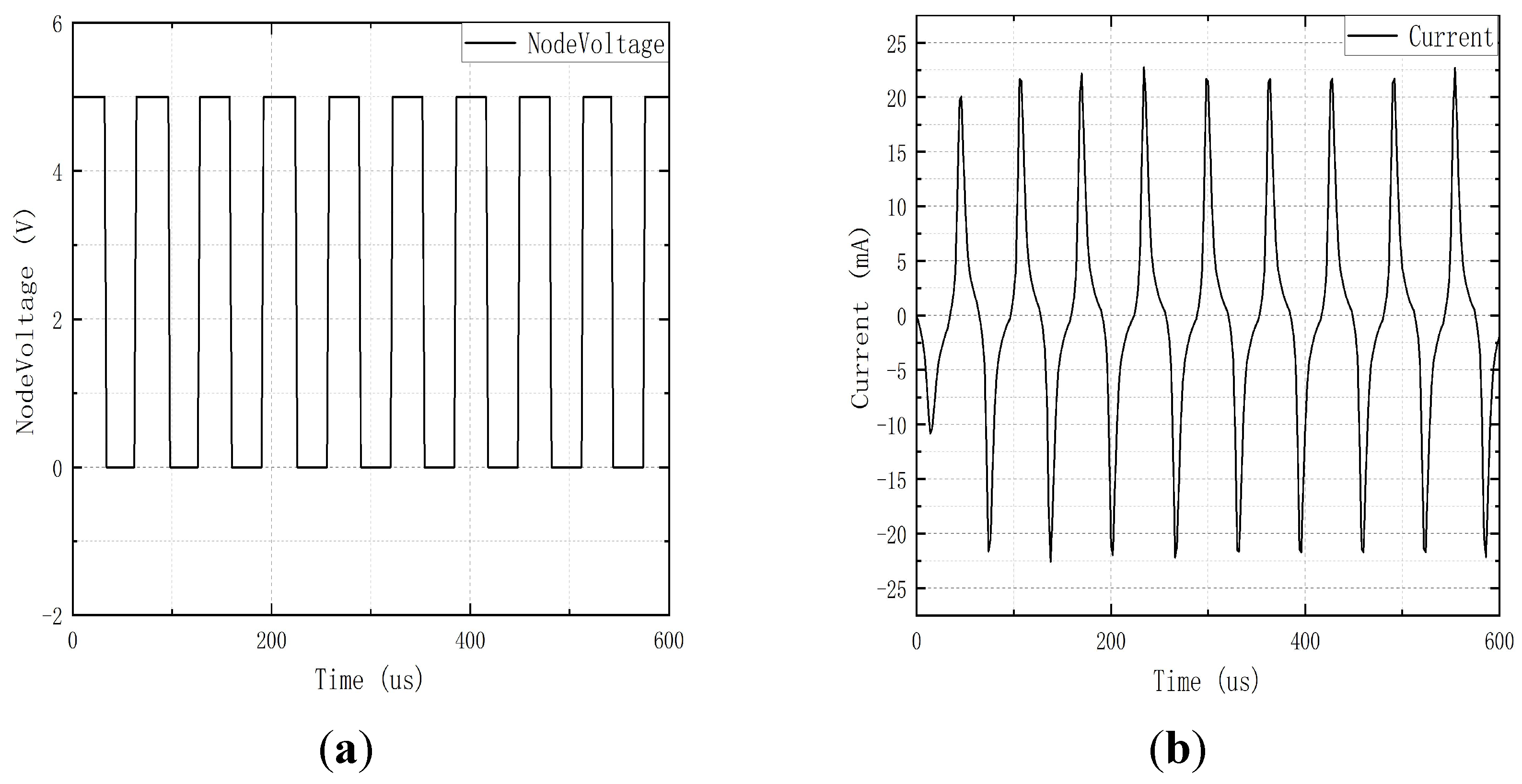
To first verify whether the fluxgate sensor meets the basic requirements, the established fluxgate model was simulated in an environment with zero external magnetic field. The excitation voltage waveform and current waveform are shown in
Figure 8. As observed, the amplitude of the excitation current smoothly changes with the transition of the excitation voltage. This is consistent with the earlier analysis of the inductive and capacitive charging and discharging behavior.
The simulation results were subjected to FFT analysis, and the outcomes are presented in
Figure 9.
It can be observed that the EMF contains a small amount of odd-order harmonics, with the maximum value being only 36.812 mV. In comparison, the second harmonic, which reflects the environmental magnetic field, is only 0.509 mV. This suggests that the noise of the fluxgate sensor is minimal, enabling it to function normally and accurately. The next step is to investigate the impact of various parameters of the fluxgate sensor’s sensing coil on its noise performance.
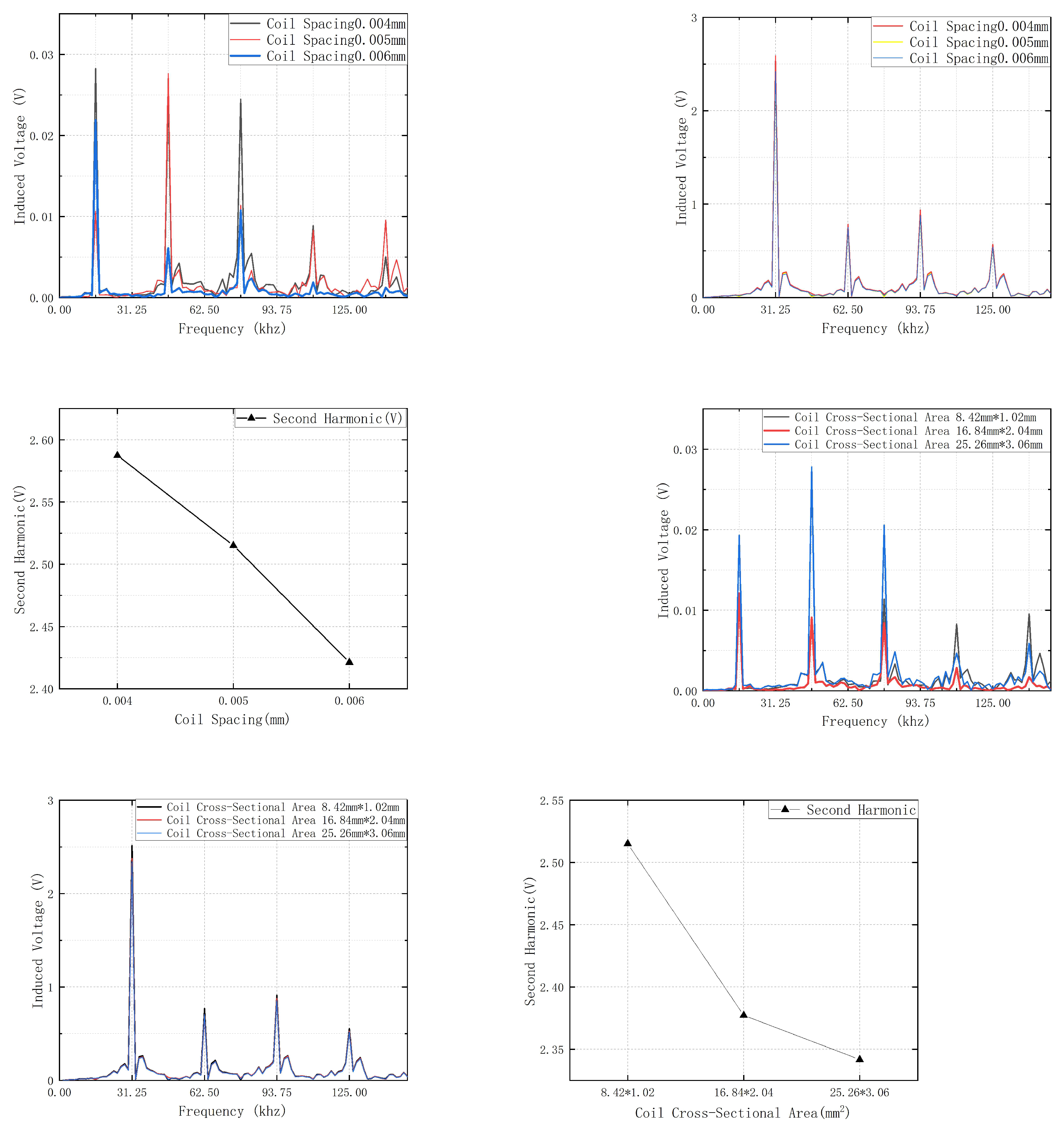
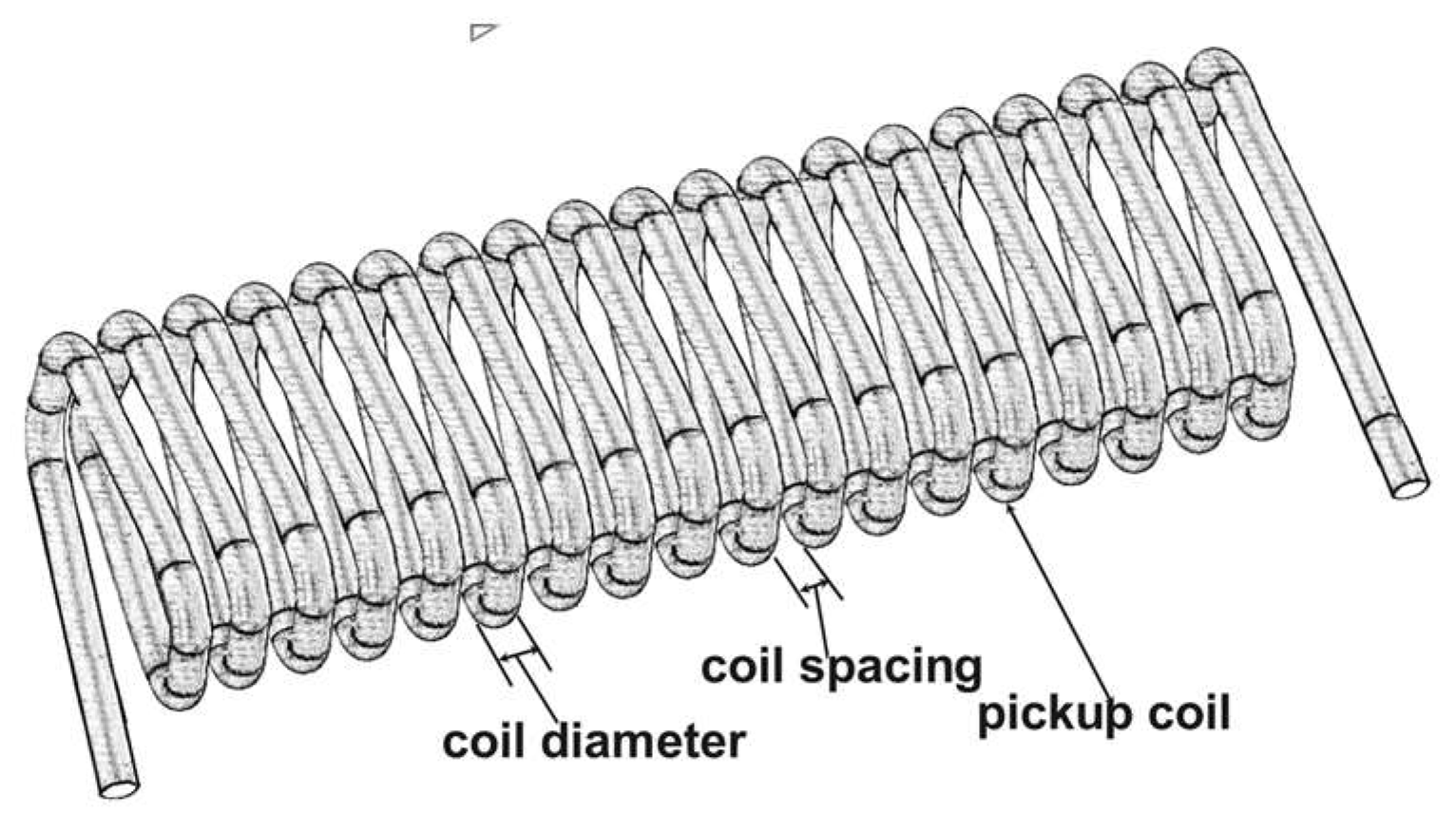
4.1. Study on the Coil Spacing of the Pickup coil
As shown in
Figure 10, the coil spacing refers to the distance between two adjacent coils.
Since the induced coil is modeled as a hollow rectangular prism representing a real coil, the coil spacing can be varied by adjusting the length of the induced coil. This can be done without changing its wire diameter. This allows for simulation of different coil spacings in the fluxgate model. By observing the variation in the second harmonic, the impact of coil spacing on magnetic field noise can be studied. This allows for simulating different coil spacings in the fluxgate model. By observing the variation in the second harmonic, the study can explore the impact of coil spacing on magnetic field noise. In this study, the coil spacing for the fluxgate sensor was designed as 0.004 mm, 0.005 mm, and 0.006 mm, with a wire diameter of 0.02 mm. This resulted in coil lengths of 28.8 mm, 30 mm, and 31.2 mm, respectively. After setting these parameters, the fluxgate coils were verified to ensure they could still operate normally after adjusting the coil spacing. This was done by checking that the second harmonic of the induced EMF approaches zero in a zero magnetic field environment. To create the necessary conditions, the solenoid model capable of generating an environmental magnetic field was first shielded. Subsequently, simulations were performed for coils with different spacings. After the simulation, FFT analysis of the results was conducted using Maxwell’s built-in functions, with the results shown in
Figure 12a.
It can be observed that the odd harmonics exhibit varying degrees of change with different coil spacings. Among them, the odd harmonics for the coil spacing of 0.006 mm have the smallest amplitude. Specifically, the first harmonic is 0.021904 V, the third harmonic is 0.006129 V, and the fifth harmonic is 0.010751 V.
In a zero magnetic field environment, the second harmonic, which reflects the environmental magnetic field, should theoretically be zero. However, in practical applications, the fluxgate sensor generates noise in the zero-field condition. To more intuitively demonstrate the impact of this noise on the fluxgate measurement results, the second harmonic value was simulated. It was treated as a pseudo-magnetic field. Through simulations, it was found that when the external magnetic field is 60,000 nT, the EMF is 2.717 V. According to Equation (6), the second harmonic of the induced EMF is proportional to the environmental magnetic field. This means that each millivolt of the second harmonic corresponds to approximately 22.083 nT of pseudo-magnetic field.
The noise and corresponding pseudo-magnetic field produced by the induced coils with different spacings are shown in
Table 1.
It can be observed that the value of the simulated magnetic field is smallest when the coil spacing is 0.006 mm. When measuring weak magnetic fields, it is important to avoid using induced coils with a spacing of 0.005 mm.
A solenoid was incorporated into the fluxgate model, and current was applied to simulate the environmental magnetic field. Simulations were performed in Maxwell for different coil spacings, and the simulation results were analyzed using FFT. The results are shown in
Figure 12b.
As shown in
Figure 12b, the spectral curves of the induced coils are very similar. Therefore, the second harmonic, which reflects the magnitude of the environmental magnetic field, is analyzed separately, as shown in
Figure 12c.
It can be observed that as the spacing between the induced coils increases, the EMF decreases. This is because, with an increased coil spacing, the distance between the coils and the magnetic core also increases. As a result, electromagnetic induction becomes insufficient. Consequently, the rate of change of magnetic flux decreases, and the induced EMF is correspondingly reduced.
Therefore, theoretically, reducing the spacing between the induced coils can enhance the sensitivity of the fluxgate sensor. However, as the coil spacing decreases, the likelihood of self-inductance between the coils increases. In practice, it is necessary to consider this trade-off to determine the optimal coil spacing.
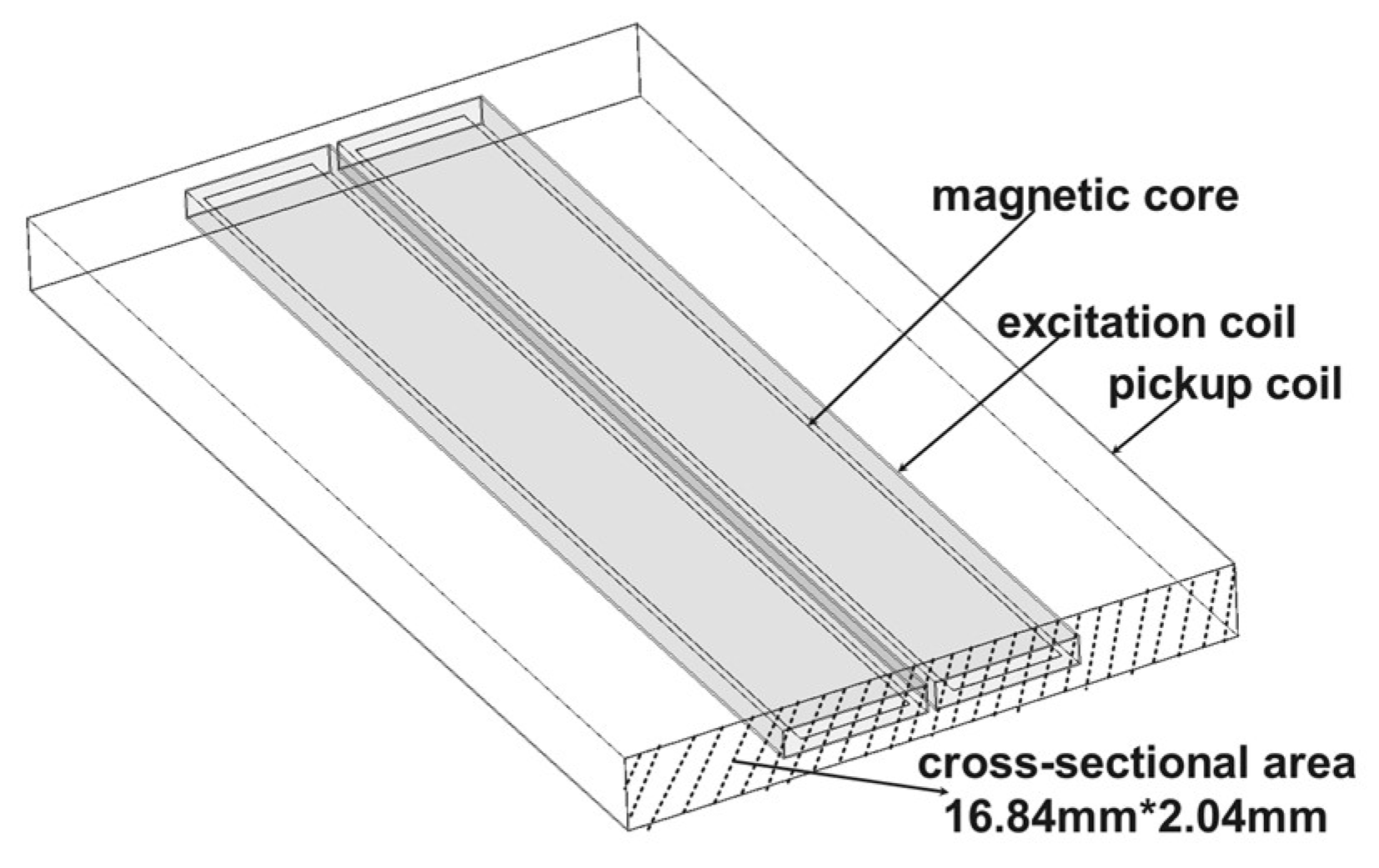
4.2. Study on the Cross-Sectional Area of the Pickup Coil
As shown in
Figure 11, this design employs three sets of induced coils with different cross-sectional areas for study.
Unlike the coil spacing, the cross-sectional area is not influenced by the number of coil turns. To more clearly observe the performance of the fluxgate sensor under different cross-sectional areas, the width of the coils was set to 8.42 mm, 16.84 mm, and 25.26 mm. The height was set to 1.02 mm, 2.04 mm, and 3.06 mm, with all other parameters held constant. The fluxgate sensor model was first analyzed in a zero-field environment, and the simulation results are shown in
Figure 12d.
As can be seen from the figure 15, the odd harmonics (1st, 3rd, and 5th) for the coil with a cross-sectional area of 25.26 mm × 3.06 mm are 0.019331 V, 0.027793 V, and 0.020588 V, respectively. These values are significantly higher than those for the coils with cross-sectional areas of 8.42 mm × 1.02 mm and 16.84 mm × 2.04 mm. This indicates that the noise amplitude in the induced electromotive force waveform is relatively high.
The noise and pseudo-magnetic field generated by the three sets of coils are summarized in
Table 2.
As shown in the table, the induced pseudo-magnetic field generated by the coil with the largest cross-sectional area is also the highest, at 12.785 nT. When measuring weak magnetic fields, the cross-sectional area of the coil should not be excessively large compared to that of the excitation coil. This is because an excessively large area could significantly affect the accuracy of the fluxgate sensor. The model with different cross-sectional areas was placed in an ambient magnetic field. After performing simulation calculations, the results were analyzed using FFT, as shown in
Figure 12e.
A separate analysis of the second harmonic is conducted, as shown in
Figure 12f.
Figure 12.
(a)Output Spectrum of Induced Electromotive Force for Different Distances of the Induced Coil under Zero Magnetic Field Condition. (b) Output Spectrum of Induced Electromotive Force for Different Distances of the Induced Coil under Environmental Magnetic Field Conditions. (c) The Second Harmonic of Induced Electromotive Force in the Induction Coil at Different Distances Under Environmental Magnetic Field Conditions. (d) Output Spectrum of Induced Electromotive Force of Pickup coils with Different Cross-sectional Areas Under Zero Magnetic Field Conditions. (e) Output Spectrum of Induced Electromotive Force of Pickup coils with Different Cross-sectional Areas Under Environmental Magnetic Field Conditions. (f) Second Harmonic of Induced Electromotive Force of Pickup coils with Different Cross-sectional Areas Under Environmental Magnetic Field Conditions.
It can be observed that as the cross-sectional area of the induction coil increases, the amplitude of the induced electromotive force decreases. This is due to the fact that a larger cross-sectional area exacerbates the issue of magnetic flux leakage in the induction coil.
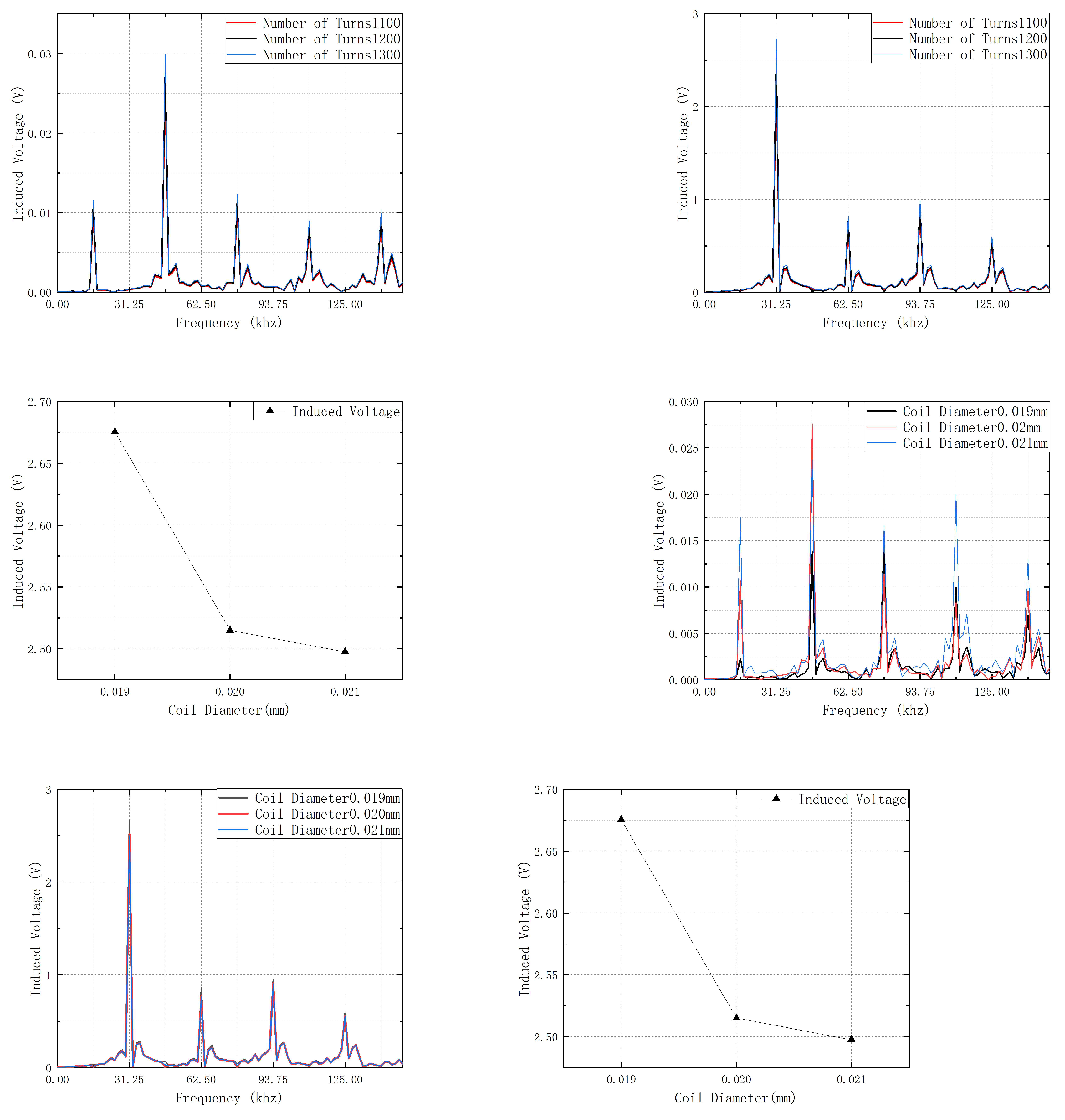
4.3. Study on the Number of Turns of the Pickup coil
When designing the number of turns in the induction coil, it is important to consider that increasing the number of turns will also increase the coil length. As a result, the ends of the induction coil may protrude compared to the excitation coil and the magnetic core. This not only wastes space, but also prevents the protruding coil from fully experiencing electromagnetic induction. As a result, it affects the induced electromotive force. Therefore, in this design, the length of the induction coil remains constant. Under this condition, the influence of wire diameter must be considered. If too many turns are used, the coil length may exceed the preset value, and the simulation results would no longer reflect realistic values. After comprehensive consideration, the number of turns in this design is set to 1100, 1200, and 1300 turns. Other parameters remain unchanged.
First, electromagnetic simulations are performed under zero magnetic field conditions, and the results are analyzed using FFT, as shown in
Figure 13a.
Unlike the results of previous designs, in this design, the odd-order harmonics increase as the number of turns in the coil increases. This indicates that with a greater number of turns, the amplitude of noise in the induced electromotive force waveform becomes larger.
The noise and spurious magnetic fields generated by the three sets of coils are summarized in
Table 3.
Similar to the odd-order harmonics, the noise level also increases with the number of turns in the coil. This indicates that the spurious magnetic field generated by the fluxgate sensor itself also increases with the number of turns in the coil. Therefore, when measuring weak magnetic fields, the number of turns in the induction coil should not be too large. A large number of turns may affect the accuracy of the magnetic field measurement.
The model was simulated and analyzed using FFT under environmental magnetic field conditions, and the results are shown in
Figure 13b.
The second-order harmonics were extracted and analyzed separately, as shown in
Figure 13c.
It can be observed that the number of turns is nearly proportional to the induced electromotive force, which also verifies Equation (6). Unlike the cross-sectional area and coil spacing, changing the number of turns in the coil directly affects the magnitude of the induced electromotive force. This is in accordance with the law of electromagnetic induction. However, an increase in the number of turns in the induction coil leads to an increase in both the internal resistance and inductance of the coil. As shown in the table, the noise also increases as the number of turns increases. Therefore, when designing the number of turns in the induction coil, the impact of noise must be considered comprehensively. Simply increasing the number of turns may negatively affect the signal quality.
4.4. Study on the Wire Diameter of the Pickup Coil
As shown in
Figure 10, the wire diameter refers to the diameter of the coil. By varying the wire diameter, the change in the induced electromotive force of induction coils with different lengths can be observed. It should be noted that, similar to the modification of coil turns, the longitudinal length of the coil model must remain unchanged when designing the wire diameter. Additionally, the cumulative length of each turn's diameter should be smaller than the longitudinal length. Therefore, the wire diameters were set to 0.02 mm, 0.025 mm, and 0.03 mm, respectively. After the setup, simulations and FFT analysis of the induction coil were conducted under zero magnetic field conditions. The results are shown in
Figure 13d.
It can be observed that the induction coil with a wire diameter of 0.019 mm has the lowest values for odd-order harmonics. The 1st, 3rd, and 5th harmonics are measured at 0.002305 V, 0.013834 V, and 0.015343 V, respectively. This indicates that the induction coil with a wire diameter of 0.019 mm generates the least amount of noise. The noise and pseudo-magnetic field generated by the three sets of coils are summarized in
Table 4.
It can be observed that as the coil diameter increases, the noise generated by the coil also increases. This indicates that a larger diameter contributes to greater noise interference. Simulations were conducted with induction coils of different wire diameters placed in an environmental magnetic field. The results were then subjected to FFT analysis, as shown in
Figure 13e.
The second harmonic was selected for separate analysis, as shown in
Figure 13f.
It can be observed that as the coil diameter increases, the induced electromotive force decreases. This is hypothesized to be due to the high frequency of magnetic field variations. Smaller diameter coils have smaller inductive areas, which makes them more effective at capturing rapid changes in the magnetic field. This allows them to respond more quickly to field variations. The faster rate of magnetic flux change within smaller diameter coils results in a more sensitive generation of the induced electromotive force.
5. Discussion
Based on the working principle of a dual-magnetic-core fluxgate, this study designs a thin-film magnetic-core fluxgate using Maxwell software. To assess the operational performance of the fluxgate, electromagnetic simulations were performed under both zero-field and environmental magnetic field conditions. The simulations investigated the influence of varying induced coil parameters on the EMF. First, the verification of Faraday’s law of electromagnetic induction was conducted. It demonstrated that both the induced EMF and noise increase linearly with the number of turns in the coil. Additionally, the intrinsic properties of the induced coil and its relative size and position in relation to the excitation coil and magnetic cores were explored. For instance, when the cross-sectional area of the induced coil is significantly larger than that of the excitation coil, the induced voltage decreases. At the same time, the noise level increases. Furthermore, when the ends of the induced coil protrude relative to the excitation coil and magnetic cores, insufficient electromagnetic induction occurs. As a result, the induced EMF decreases as the distance between the induced coil and the excitation coil increases. Finally, a new perspective is presented: when the wire diameter is 0.02 mm, a slight reduction in wire diameter can enhance the induced EMF and increase the sensitivity of the fluxgate sensor. It can also reduce interference. In summary, this paper provides a systematic study of the induced coil in the fluxgate, offering valuable insights for the design of magnetic probe coils.
Author Contributions
Conceptualization, Z.L.; data curation, P.W.; methodology, Z.L.; investigation, P.W.; resources, Z.L.; visualization, P.W.; supervision, Z.L.; Writing-original draft, P.W.; Writing - review & editing, P.W.. All authors have read and agreed to the published version of the manuscript.
Institutional Review Board Statement
Not applicable.
Informed Consent Statement
Not applicable.
Data Availability Statement
The datasets generated during and/or analyzed during the current study are available from the corresponding author on reasonable request.
Conflicts of Interest
The authors declare no conflicts of interest.
Abbreviations
The following abbreviations are used in this manuscript:
| FFT |
Fast Fourier Transform |
| EMF |
electromotive force |
References
- Wang, N.; Zhang, Z.; Li, Z.; Zhang, Y.; He, Q.; Han, B.; Lu, Y. Self-Oscillating Fluxgate-Based Quasi-Digital Sensor for DC High-Current Measurement. IEEE Trans. Instrum. Meas. 2015, 64, 3555–3563. [CrossRef]
- Yang, X.; Li, Y.; Zheng, W.; Guo, W.; Wang, Y.; Yan, R. Design and Realization of a Novel Compact Fluxgate Current Sensor. IEEE Trans. Magn. 2015, 51, 1–4. [CrossRef]
- Yang, X.; Guo, W.; Li, C.; Zhu, B.; Pang, L.; Wang, Y. A Fluxgate Current Sensor With a U-Shaped Magnetic Gathering Shell. IEEE Trans. Magn. 2015, 51, 1–4. [CrossRef]
- Trigona, C.; Sinatra, V.; Ando, B.; Baglio, S.; Bulsara, A.R. Flexible Microwire Residence Times Difference Fluxgate Magnetometer. IEEE Trans. Instrum. Meas. 2017, 66, 559–568. [CrossRef]
- Li, J.; Zhang, X.; Shi, J.; Heidari, H.; Wang, Y. Performance Degradation Effect Countermeasures in Residence Times Difference (RTD) Fluxgate Magnetic Sensors. IEEE Sensors J. 2019, 19, 11819–11827. [CrossRef]
- Wrzecionko, B.; Steinmann, L.; Kolar, J.W. High-Bandwidth High-Temperature (250 °C/500 °F) Isolated DC and AC Current Measurement: Bidirectionally Saturated Current Transformer. IEEE Trans. Power Electron. 2013, 28, 5404–5413. [CrossRef]
- Schrittwieser, L.; Mauerer, M.; Bortis, D.; Ortiz, G.; Kolar, J.W. Novel Principle for Flux Sensing in the Application of a DC + AC Current Sensor. IEEE Trans. Ind. Appl. 2015, 51, 4100–4110. [CrossRef]
- Yang, X.; Li, Y.; Guo, W.; Zheng, W.; Xie, C.; Yu, H. A New Compact Fluxgate Current Sensor for AC and DC Application. IEEE Trans. Magn. 2014, 50, 1–4. [CrossRef]
- Li, J.; Zhang, X.; Shi, J.; Heidari, H.; Wang, Y. Performance Degradation Effect Countermeasures in Residence Times Difference (RTD) Fluxgate Magnetic Sensors. IEEE Sensors J. 2019, 19, 11819–11827. [CrossRef]
- Djamal M, Sanjaya E. Development of fluxgate sensors and its applications[C]//2011 2nd International Conference on Instrumentation, Communications, Information Technology, and Biomedical Engineering. IEEE, 2011: 421-426.
- Lepping, R.P.; Acũna, M.H.; Burlaga, L.F.; Farrell, W.M.; Slavin, J.A.; Schatten, K.H.; Mariani, F.; Ness, N.F.; Neubauer, F.M.; Whang, Y.C.; et al. The WIND magnetic field investigation. Space Sci. Rev. 1995, 71, 207–229. [CrossRef]
- Auster, H.U.; Glassmeier, K.H.; Magnes, W.; Aydogar, O.; Baumjohann, W.; Constantinescu, D.; Fischer, D.; Fornacon, K.H.; Georgescu, E.; Harvey, P.; et al. The THEMIS Fluxgate Magnetometer. Space Sci. Rev. 2008, 141, 235–264. [CrossRef]
- LENZ, James; EDELSTEIN, S. Magnetic sensors and their applications. IEEE Sensors journal, 2006, 6.3: 631-649.
- Murzin, D.; Mapps, D.J.; Levada, K.; Belyaev, V.; Omelyanchik, A.; Panina, L.; Rodionova, V. Ultrasensitive Magnetic Field Sensors for Biomedical Applications. Sensors 2020, 20, 1569. [CrossRef]
- Butta, M.; Vazquez, M.; del Real, R.P.; Calle, E. Dependence of the noise of an orthogonal fluxgate on the composition of its amorphous wire-core. AIP Adv. 2020, 10, 025114. [CrossRef]
- Janosek, M.; Butta, M.; Dressler, M.; Saunderson, E.; Novotny, D.; Fourie, C. 1-pT Noise Fluxgate Magnetometer for Geomagnetic Measurements and Unshielded Magnetocardiography. IEEE Trans. Instrum. Meas. 2019, 69, 2552–2560. [CrossRef]
- Paperno E. Suppression of magnetic noise in the fundamental-mode orthogonal fluxgate[J]. Sensors and Actuators A: Physical, 2004, 116(3): 405-409. [CrossRef]
- Zhang C, Zhang Y, Wang X, et al. A method to reduce excitation circuit noise of fluxgate sensor[J]. Modern Physics Letters B, 2022, 36(07): 2150606. [CrossRef]
- Ripka P, Primdahl F. Tuned current-output fluxgate[J]. Sensors and Actuators A: Physical, 2000, 82(1-3): 161-166. [CrossRef]
- Priftis P, Angelopoulos S, Ktena A, et al. Development of a high-sensitivity orthogonal fluxgate sensor[J]. Journal of Magnetism and Magnetic Materials, 2024, 590: 171646. [CrossRef]
- Dezuari O, Belloy E, Gilbert S E, et al. Printed circuit board integrated fluxgate sensor[J]. Sensors and Actuators A: Physical, 2000, 81(1-3): 200-203. [CrossRef]
- Wei S, Liao X, Zhang H, et al. Recent progress of fluxgate magnetic sensors: Basic research and application[J]. Sensors, 2021, 21(4): 1500. [CrossRef]
- Ripka P. Review of fluxgate sensors[J]. Sensors and Actuators A: Physical, 1992, 33(3): 129-141. [CrossRef]
- Primdahl F. The fluxgate magnetometer[J]. Journal of Physics E: Scientific Instruments, 1979, 12(4): 241. [CrossRef]
- Shen X, Teng Y, Hu X. Design of a low-cost small-size fluxgate sensor[J]. Sensors, 2021, 21(19): 6598. [CrossRef]
- Ripka P. New directions in fluxgate sensors[J]. Journal of Magnetism and Magnetic Materials, 2000, 215: 735-739. [CrossRef]
|
Disclaimer/Publisher’s Note: The statements, opinions and data contained in all publications are solely those of the individual author(s) and contributor(s) and not of MDPI and/or the editor(s). MDPI and/or the editor(s) disclaim responsibility for any injury to people or property resulting from any ideas, methods, instructions or products referred to in the content. |
© 2025 by the authors. Licensee MDPI, Basel, Switzerland. This article is an open access article distributed under the terms and conditions of the Creative Commons Attribution (CC BY) license (http://creativecommons.org/licenses/by/4.0/).