
Submitted:
04 March 2025
Posted:
05 March 2025
You are already at the latest version
Abstract
This study investigates the effect of incorporating an electromagnetic harvester inside the bluff body of a 2-DoF hybrid harvester in comparison to a standalone piezoelectric harvester for various external loads. The design consists of an electromagnetic harvester embedded inside a cylindrical bluff body, which is attached to the free end of a composite PZT cantilever beam. The harvester is excited through a vortex-induced vibration owing to the resultant wake vortices created behind the bluff body. The coupled equations of motion of the harvester are derived using the lumped-mass equivalent representation and Lagrange formulation. Numerical results show that at high operating flow speed and large electrical load, the standalone piezoelectric harvester outperforms the hybrid harvester. Nevertheless, for small electrical loads and at low-speed flow, the hybrid harvester outperforms the standalone ones for a wider range of the flow speed. In these operating conditions, numerical simulations also showed that an optimum spring stiffness of the electromagnetic harvester exists at a certain flow speed for a maximized harvested output power. In general, such hybrid energy harvester showed to be more effective at low-speed fluid flow and small electrical loads.
Keywords:
piezoelectric
; electromagnetic
; hybrid energy harvester
; vortex induced vibration
; internal resonance
1. Introduction
Energy harvesting devices are sustainable and environmentally friendly solutions for powering electronics. They can be categorized by observing their assumed transduction mechanisms, including piezoelectric [1], electromagnetic [2], electrostatic [3], thermoelectric [4], triboelectric [5], or a hybrid combination of these mechanisms [6]. The energy conversion mechanism of these harvesters is to harness energy from various ambient sources and converting it into electrical energy that can be stored and used [7]. For instance, vibration-based energy harvesters convert the ambient mechanical vibrations to an electrical energy. Among the various ambient sources, wind energy is an abundant and renewable source of energy that induces various modes of harvester oscillations such as: galloping [8], fluttering [9], and vortex-induced vibrations (VIV) [10].
VIV wind energy harvesters offer a higher wind speed bandwidth (i.e., the lock-in region or the usable wind speed range) and require a lower onset wind velocity to harness energy compared to other oscillation modes [11]. A typical VIV harvester features a piezoelectric ceramic (PZT) sheet mounted near the fixed end of a cantilever substrate with a cylindrical bluff body attached at the free end. Recently, several approaches have been proposed to enhance the performance of the VIV-based harvesters. This include introducing nonlinear magnetic restoring forces, increasing the harvester’s degree of freedom, integration of multiple transduction mechanisms (i.e., a hybrid harvester), and combing VIV and galloping oscillations into a single harvester. Both theoretical and experimental research investigations have significantly contributed to different designs of VIV wind energy harvesters enhancing their output power, bandwidth, and efficiency.
Hou et al. [12] examined a magnet-induced, monostable nonlinear, VIV piezoelectric energy harvester. The study reported that the bandwidth and output power for such a design increase with an increase in the bluff body diameter and length of the PZT layer, and a decrease in the bluff body mass. Nasser et al. [13] performed a performance analysis of piezo-magnetoelastic energy harvesting from VIVs by using monostable characteristics. The analysis showed a left shift in the synchronization region of the harvester, which in turn is very beneficial for a higher efficiency for the energy harvesting at low wind speed conditions. Furthermore, the harvester design exhibited a monostable hardening behavior mainly resulting from the assumed nonlinear magnetic force, offering the prospect to use such design arrangement as an ultra-wide bandwidth VIV-based energy harvester with an enhanced output energy performance when the ambient wind condition is variable. Su and Wang [14] investigated numerically and experimentally a bi-directional VIV-based PEH to capture wind energy simultaneously from the vertical and horizontal directions. A set of magnets was assumed to enhance the harvesting performances. The resultant generated magnetic force improved the harvester lock-in region and an enhancement of the peak voltage of the horizontal mode but had slight effect on the vertical direction.
Combining the oscillation modes can enhance the performance of the VIV-based harvesters. Yang et al. [15] investigated the aerodynamic parametric influence on the performance of a piezoelectric wind energy harvester subjected to a coupled VIV and galloping oscillations. They have suggested an effective structural optimization of the bluff body geometry, through a genetic algorithm, for an energy harvesting enhancement. By introducing a coupled VIV-galloping parameter, an interesting hump phenomenon was observed. Although the coupling parameter degrades harvester performance in low wind speed, it improves the output voltage at wind speed above 1.6 m/s. Hou et al. [16] developed experimentally and analyzed theoretically a hybrid PEH to scavenge a VIV superimposed to a base excitation oscillation. The hybrid harvesting design increases the harvested peak power and bandwidth as compared to that under base excitation or VIV only. As such, combining oscillation is suggested, when possible, to harness more power at a higher bandwidth.
In vibration-based energy harvesters, the peak energy output occurs near the fundamental resonance of the system. By increasing the harvester's degrees of freedom (DOF), additional resonances are introduced, effectively broadening the operational bandwidth. Aligned with this objective, Lu et al. [17] investigated, using numerical simulations, the energy harvesting performance of a two degree of freedom VIV small-scale wind energy harvester and where the aerodynamic exciting force was modeled assuming a wake oscillator model with some assumed empirical parameters. Their study showed the existence of two “lock-in” regions beneficial for broadening the useful wind energy bounds.
Sun and Seok [18] recommended an innovative self-tuning VIV wind energy harvesting system, assuming a moving bluff body. Such self-tuning design showed proficiencies to broaden the frequency lock-in range and enhance accordingly the harvester’s overall energy efficiency performances. Lai et al. [19] proposed a hybrid piezoelectric-dielectric energy harvester to convert energy from VIVs into electricity using both the piezoelectric ceramic (PZT) sheets and the vibro-impact dielectric elastomer generator. Their numerical simulations showed that such design is capable in harvesting wind energy effectively within a narrow low wind speed range, as compared to the prevailing galloping-based wind energy harvesters.
Hybrid piezoelectric-electromagnetic harvesters (PEH) are generally utilized to increase the output power and the operational bandwidth. Zhang et al. [20] suggested a hybrid VIV piezoelectric-electromagnetic harvester attached to a direction adaptive mechanism (a rotating shaft) permitting harvesting wind energy from different directions. It was also observed experimentally that the performance of the energy harvester improved through increasing the bandwidth and decreasing the onset wind speed by adding an extra mass to the lower end of the rotating shaft. To further improve the VIV harvester efficiency, Al-Riyami et al. [6] explored using a hybrid VIV PEH that comprises a PZT cantilever beam and an embedded electromagnetic harvester inside the bluff body. The design is to increase the DoFs and combine two transduction mechanisms in a single harvester. Numerical analysis showed that the harvester power and wind speed bandwidth extended near the two resonances of the harvester. However, a recent study by Truong et al. [21] shows that a linear hybrid PEH generates less power than standalone piezoelectric or electromagnetic harvesters when the electrical losses of one of them or both components exceed a certain figure of merit threshold. As such, this suggests the need for careful design considerations when optimizing PEH under a given external load. Nonetheless, the PEH remains recommended approach for broadening the operational bandwidth.
In this work, the dynamics of a piezoelectric-electromagnetic VIV energy harvester is examined. The harvester under study was previously investigated at various boundary conditions in [22,23]. Experimental results indicated a modest 23% improvement in the output voltage of the hybrid energy harvester compared to the conventional standalone piezoelectric harvester, suggesting the need for a more detailed dynamic analysis of the harvester to optimize both the output power and bandwidth. The main contribution of this paper lies in developing a nonlinear dynamic model of the harvester and conducting a parametric analysis of the key components of the harvester. Additionally, a comparative performance analysis of the hybrid harvester against a stand-alone piezoelectric harvester at different external loads is performed. Section 2 describes the harvester’s design and components. The piezo-electromagnetic dynamic model driven by vortex-induced vibrations is developed in Section 3. Section 4 outlines the findings of the numerical analysis and the parametric study. Conclusions are summarized in Section 5.
2. Harvester Design and Components
This section presents the design geometry and structure of the proposed hybrid energy harvester, which integrates both piezoelectric and electromagnetic transduction mechanisms to harness energy from vortex-induced vibrations (VIV). The design combines the advantages of the two transduction mechanisms to increase the degrees of freedom of the system, thereby expanding the operational bandwidth.
The schematic representation of the hybrid harvester is depicted in Figure 1. The harvester features a bluff body mounted on the free end of an aluminum-PZT composite cantilever beam. As the bluff body oscillates due to vortex shedding, strain is induced in the piezoelectric layer generating an electrical output. Additionally, an electromagnetic (EM) harvester that consists of a coil and a spherical permanent magnet is embedded within the bluff body. When the bluff body oscillates, the magnetic moves relative to the coil inducing a current in the coil so an additional electrical energy is generated. It is worth mentioning that the spherical permanent magnet is strained to move along the longitudinal axis of the bluff body, guided by compressive springs.
The overall performance of the harvester, in terms of the output power and bandwidth, is influenced by several key design parameters such as the substrate material properties and geometry, bluff body mass and dimensions, and spring stiffness. For instance, research studies have shown that an excessive bluff body mass degrades the total output power of the harvester [24]. Furthermore, the spring stiffness can be used as a controlled parameter to maximize the output power within a narrow flow speed as it will be demonstrated in section 4. The parameters and material properties of the hybrid energy harvester are listed in Table 1. The detailed description of the actual manufactured harvester is presented in [22]. The coupled dynamic model of the harvester that incorporates all design parameters is outlined in the next section.
3. Piezo-Electromagnetic Dynamic Model
In this section, the nonlinear dynamic model of the hybrid piezo-electromagnetic harvester under vortex-induced vibration (VIV) is developed using the Lagrange formulation. The lumped-mass equivalent dynamic model of the harvester is illustrated in Figure 2. The electromagnetic (EM) harvester inside the bluff body is modeled as a linear oscillator attached to a lumped mass representing the composite piezoelectric (PZT) harvester. As the PZT harvester oscillates due to the VIV force, the magnet inside the bluff body moves linearly relative to the electromagnetic coil. This coupled motion results in a nonlinear interaction between the harvesters. The electrical energy generated by both harvesters is represented by resistive loads ( and ), as shown in Figure 2.
The equations of motion for the hybrid harvester are derived using the following Lagrange formulation [25],
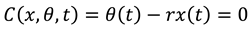
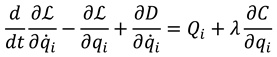 where represents the Lagrangian, defined as the difference between the kinetic () and potential () energies of the harvester. For , denotes the generalized coordinates of the harvester which include the beam deflection (), the bluff body rotation angle (), the magnet sliding motion () relative to the bluff body and its attached coil, the piezoelectric charge (), and the electromagnetic charge (). are the generalized forces acting on the harvester and represents the Rayleigh dissipation function of the harvester. It is worth mentioning that the rotational motion of the bluff body is constrained by the beam deflection, as the bluff body is fixed to the free end of the beam rather than being pivoted for free rotation. Thus, Lagrange multiplier () is introduced to enforce restriction on the rotational motion of the bluff body. The constraint equation that corelate the rotational angle of the bluff body and the beam deflection is expressed as
 in which, the parameter is calculated by [25]
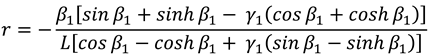 where and are the first eigenvalue and modal parameter of a cantilever beam carrying a tip mass, respectively. is the substrate beam length.
The kinetic energy of the coupled harvester is given by
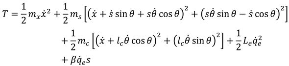 where represents the total mass of the beam equivalent mass and bluff body mass. and are the equivalent spring stiffness and the total damping of the composite PZT beam, respectively. The coil mass is denoted as while is the linear spring stiffness attached to the sliding mass of the magnet (). and are the electromagnetic charge and coil inductance, respectively. is the electromagnetic coupling factor. represents the distance from the end of the composite beam to the center of mass of the coil.
The harvester’s potential energy arises from the elastic deformation of the composite PZT beam, the restoring force from the spring attached to the sliding magnet, the gravitational potential energy, and the piezoelectric energy. As such, the total potential energy of the harvester is given by
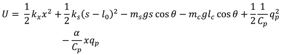
Here, and are the charge and the capacitance of the piezoelectric layer, respectively. The initial length of the spring attached to the sliding magnet is represented by . is the electromechanical coupling coefficient of the PZT harvester.
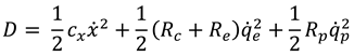
The harvester is assumed to be fully submerged in water. Therefore, the dissipation energy in the harvester is due to the drag force exerted by the surrounding water, the resistive loads, and the coil electrical resistance (). The dissipation function is expressed by the following term
In addition, the harvester is excited only by the lift VIV force () due to vortex shedding beyond the bluff body. To capture oscillatory phenomena of the vortex shedding, the vortex-induced vibrations are modeled using a Van der Pol oscillator [26]. Thus, the generalized force which is the VIV force () is then given by
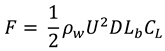 where is the density of water. and are the diameter and length of the bluff body, respectively. denotes the water stream speed across the bluff body. is the lift coefficient, expressed by [26]
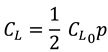 in which, is the static lift coefficient of a fixed cylinder that is approximately 0.3 for Reynold’s numbers (Re) between 103 and 105 [26]. is the wake variable of the Van der Pol oscillator that captures the alternating motion and the lock-in phenomena of the vortex shedding. The Van der Pol oscillator equation is given as
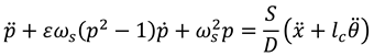 where is the vortex shedding frequency, in which denotes the Strouhal number (approximately 0.2 for 300 < Re < 106). The parameters S and ε are oscillator tuning parameters to fit the experimental data. The approximate values of these tuning parameters used in this study are 12 and 0.3, respectively.
Substituting equations (2-5) in Lagrange formulation given in (1), the equations of motion for the hybrid energy harvester are obtained. The resulting set of equations that represents the coupled nonlinear dynamics of the harvester are
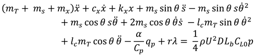
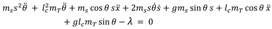

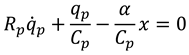

Equation (14) represents the constrain equation between the beam deflection and the rotational angle of the bluff body. Here, represents the total mass, including the coil mass and the fluid added mass (). The set of equations of motion are solved numerically using MATLAB ode45 solver with the system parameters listed in Table 1. The total output electrical power () of the harvester is subsequently calculated as
It is evident that the equations of motion are highly coupled. For example, the piezoelectric charge () affects that beam deflection () and vice versa, as shown in equations (8) and (11). Additionally, in equation (12), the sliding motion of the magnet () influences the electromagnetic output charge (). This coupling extends further to the interaction between the beam deflection (or bluff body rotation) and the sliding motion of the magnet. This interaction results in nonlinear centrifugal and Coriolis () forces. In such coupled systems, dynamic nonlinearities can potentially degrade the output power and bandwidth of the harvester. Therefore, careful consideration is essential during designing a hybrid harvester, as will be shown by the analytical results presented in the following section.
4. Results and Discussion
The hybrid piezoelectric-electromagnetic harvester under study was manufactured and experimentally investigated in our previous work [Asan1], using the harvester parameters and material properties listed in Table 1. The harvester is assumed to be fully submerged in an open water channel, with the flow occurring perpendicular to the bluff body, causing it to oscillate due to vortex shedding. In this section, the results of the numerical simulations are presented. The primary objective of this study is to examine the contribution of the electromagnetic (EM) harvester or oscillaotr to the overall performance of the hybrid harvester. The EM harvester is modeled dynamically as a spring-mass oscillator attached to the free end of the piezoelectric composite harvester.
The analysis compares the RMS output power of the standalone piezoelectric harvester with that of the hybrid harvester. To ensure a valid comparison, both harvesters should have the same total mass and geometry. For this reason, the hybrid harvester is treated as a standalone piezoelectric harvester when the spring attached to the sliding magnet inside the bluff body is sufficiently stiff. As such, the spring stiffness is set to 106 N/m, representing the standalone piezoelectric harvester.
The hybrid harvester represents a 2-DoF system, namely the beam deflection () and the sliding motion of the magnet (). The fundamental frequency of the hybrid harvester, as simulated in this study, is 3.42 Hz, which closely matches the experimentally measured value of 3.20 Hz from our previous work. The second natural frequency of the harvester is numerically estimated to be 6.82 Hz as shown in the amplitude spectrum of the harvester in Figure 3. The ratio of these two frequencies is approximately 1:2, indicating an internal resonance phenomenon, which could potentially lead to enhanced energy transfer between the components, depending on the system's operating conditions.
Figure 4 shows the output power of the hybrid piezoelectric-electromagnetic harvester at a water flow speed of 0.3 m/s at its optimum electrical loads of = 0.4 MΩ and = 1.25 Ω. The RMS power of the piezoelectric harvester contributes of 0.1977 mW in the total power, whereas the electromagnetic harvester generates only 0.0092 mW, which is 20 times lower than the piezoelectric harvester. In comparison, the simulation results of a standalone piezoelectric show a comparable output power of 0.2051 mW. This indicates that adding an electromagnetic harvester does not significantly enhance the output performance of a hybrid harvester. However, further numerical investigations are required to explore this further as outlined in the next analysis.
Figure 5 shows the RMS output power of both the hybrid and standalone PZT harvesters at an optimum external load of 0.4 MΩ. The results indicate that the standalone PZT harvester outperforms the hybrid harvester at higher water flow speeds, while the performance of both harvesters is comparable at lower speeds. Additionally, the bandwidth, or the span of the lock-in region, is broader for the standalone PZT harvester than for the hybrid harvester. This suggests that the standalone PZT harvester has the potential for greater performance at this optimal electrical load. The simulation is repeated at a lower electrical load of 0.04 MΩ, as shown in Figure 6. Although the standalone PZT harvester has a slightly broader lock-in region, the hybrid harvester generates more RMS output power. In both cases, the hybrid harvester has a lower onset flow speed at which power is generated. This indicates that the hybrid harvester under study is preferable for low-speed flow and low electrical loads applications, suggesting that the electromagnetic component enhances the overall performance when the load is not maximized.
The spring stiffness attached to the magnet is a key design parameter that can be tuned to optimize the harvester's output power across different water flow speeds and external electrical loads. To examine the effect of spring stiffness and, thus, the EM harvester on the overall performance of the hybrid system, the following analysis considers the harvester at two flow speeds (), 0.30 m/s and 0.38 m/s, and two external loads (), 0.4 MΩ and 0.04 MΩ. Figure 7 illustrates both the total output power and the individual contributions of each harvester as the spring stiffness varies, at a flow speed of 0.3 m/s and an electrical load of 0.40 MΩ. At this flow speed and load, the output power peaks when the spring stiffness is set to 25.8 N/m. Notably, at this optimal spring stiffness, the total power of the hybrid harvester is mainly generated by the PZT harvester, with minimal contribution from the EM harvester. The EM harvester generates maximum output power when the spring stiffness is approximately 83.56 N/m. But, at this spring stiffness, the power from the PZT harvester decreases considerably, causing the overall power to decrease. In this case, the EM harvester is treated as an absorber that suppresses the PZT beam vibrations and, hence, reduces the overall output power of the harvester.
It is important to note that the EM harvester still plays a dynamic role in enhancing the overall performance of the hybrid harvester. The oscillatory motion of the magnet in the EM harvester contributes to the dynamics of the hybrid harvester that increases the output power. As mentioned earlier, the hybrid harvester behaves like a standalone PZT harvester when the spring stiffness is sufficiently high. Figure 7 clearly shows that as spring stiffness increases towards 150 N/m, the output power decreases. In these operating conditions, this confirms that the hybrid harvester outperforms the standalone PZT harvester due to its coupled dynamics, even though the EM harvester does not directly contribute to the total output power.
Figure 8 shows the output power of the hybrid harvester as the spring stiffness varies, with a higher flow speed of 0.38 m/s and an external load of 0.40 MΩ. As the spring stiffness increases, the power also increases. This clearly indicates that the standalone PZT harvester is preferable under these operating conditions. The EM harvester produces maximum electrical power at a spring stiffness of 87.44 N/m. However, the power generated by the EH harvester is extracted from the PZT harvester, which reduces the overall power of the hybrid system. The PZT harvester remains the primary source of power across various spring stiffness values, and no dynamic benefits from using the EM harvester are observed under these conditions.
The effect of spring stiffness on the overall output power of the hybrid harvester at lows flow speed of 0.3 m/s and high external load of 0.04 MΩ is illustrated in Figure 9. As the spring stiffness increases, the total output power rises at a peak around 83.56 N/m. At this point, the EM harvester generates its maximum power, while the contribution of the PZT harvester decreases. In this configuration, it is evident that the EM harvester contributes more to the overall power of the hybrid harvester near its optimum spring stiffness. However, this is attributed to the significant reduction in the PZT harvester’s output power under a low external electrical load that is much lower than its optimum value of 0.4 MΩ. Overall, this demonstrates that the hybrid harvester outperforms the standalone PZT harvester at low external loads. The final operating condition considers the hybrid harvester at a flow speed of 0.38 m/s at an electrical load of 0.04 MΩ. The output power of the hybrid harvester at various spring stiffness is presented in Figure 10. In general, the performance of the harvester is similar to the case presented in the previous section. The EM harvester contributes more to the overall power near an optimum spring stiffness.
The coupled dynamics between both harvesters at this optimum spring stiffness result in increased output power. From the equations of motion, the sliding magnet in the EM harvester is driven at the second harmonic of the PZT harvester. Therefore, the EM harvester power is maximized when the second harmonic of the PZT harvester matches the EM harvester resonance. In this scenario, the hybrid harvester is operating under a 1:2 internal resonance. However, meeting this condition does not necessarily guarantee that the hybrid harvester generates more power than the standalone PZT harvester. This is demonstrated in Figure 8, where, at high flow speed and high electrical load, the standalone PZT harvester produces more power than the hybrid harvester, even when it is at its 1:2 internal resonance status.
5. Conclusion
In this study, the dynamics of a hybrid piezoelectric-electromagnetic energy harvester driven by vortex-induced vibration are investigated. The equations of motion reveal a strong coupling between the various electrical and mechanical domains of the harvester. The primary objective of the numerical analysis is to evaluate the contribution of the electromagnetic harvester to the overall performance of the hybrid system in comparison to a standalone PZT harvester. The numerical results show that the hybrid harvester outperforms the standalone piezoelectric at low electrical loads and low-speed water flow. In particular, the electromagnetic harvester enhances the output power of the hybrid harvester in two ways: i) by directly contributing to the output power, and ii) by dynamic interaction with the piezoelectric harvester to increase its output power.
Optimal spring stiffness values that maximize the output power of the hybrid harvester are identified under various operating conditions. At low electrical loads, the optimal spring stiffness corresponds to the point where the EM harvester's power is at its maximum, contributing most to the overall output power. This is attributed to the internal resonance phenomena that enhances energy exchange between the harvester components. However, beyond this optimal value, the contribution of the EM harvester becomes minimal. At higher flow speed and electrical loads, the standalone PZT harvester generates higher output power. This is because the electromagnetic part is acting as an auxiliary oscillator or damped that suppresses the dynamics of the hybrid harvester, resulting a reduction in the output power.
This conclusion is in an agreement with the findings in the recent study by Truong et al. [21]. Their study revealed that a linear hybrid harvester generates less power than a standalone piezoelectric when the electrical loads exceed a certain figure of merit threshold. As such, further numerical investigations are necessary to refine the design of the hybrid harvester and enhance its performance at varying load conditions and flow speeds. A dimensionless analysis of the hybrid harvester could provide in-depth insights about the general design criteria for an optimized hybrid harvester with output power greater than a standalone PZT under various operating conditions.
References
- Abdollahzadeh Jamalabadi, M.Y.; Shadloo, M.S.: Karimipour, A. Maximum Obtainable Energy Harvesting Power from Galloping-Based Piezoelectrics. Math. Probl. Eng., 1–8 (2020). [CrossRef]
- Foong, F.M.; Thein, C.K.; Yurchenko, D.: Important considerations in optimising the structural aspect of a SDOF electromagnetic vibration energy harvester. J. Sound Vib., 482, 115470 (2020). [CrossRef]
- Erturun, U.; Eisape, A.; West, J.E:. Design and analysis of a vibration energy harvester using push-pull electrostatic conversion. Smart Mater. Struct., 29, 105018 (2020). [CrossRef]
- Champier, D.: Thermoelectric generators: A review of applications. Energy Convers. Manag., 140, 167–181 (2017). [CrossRef]
- Hamid, H.M.A.; Çelik-Butler, Z. A novel MEMS triboelectric energy harvester and sensor with a high vibrational operating frequency and wide bandwidth fabricated using UV-LIGA technique. Sens. Actuators A Phys. 2020, 313, 112175. [Google Scholar] [CrossRef]
- Al-Riyami, M., Bahadur, I., & Ouakad, H. (2022). There is plenty of room inside a bluff body: A hybrid piezoelectric and electromagnetic wind energy harvester. Energies, 15(16), 6097. [CrossRef]
- Sodano, H.A.; Inman, D.J.; Park, G. A review of power harvesting from vibration using piezoelectric materials. Shock Vib. Dig. 36, 197–206 (2004). [CrossRef]
- Li, X., Bi, C., Li, Z., Liu, B., Wang, T., & Zhang, S.: A piezoelectric and electromagnetic hybrid galloping energy harvester with the magnet embedded in the bluff body. Micromachines, 12(6), 626 (2021). [CrossRef]
- Li, K.; Yang, Z.; Zhou, S. Performance enhancement for a magnetic-coupled bi-stable flutter-based energy harvester. Smart Mater. Struct., 29, 085045 (2020). [CrossRef]
- Akaydin, H.D.; Elvin, N.; Andreopoulos, Y. The performance of a self-excited fluidic energy harvester. Smart Mater. Struct., 21, 25007 (2012). [CrossRef]
- Wu, Y., Cheng, Z., McConkey, R., Lien, F. S., & Yee, E. (2022). Modelling of flow-induced vibration of bluff bodies: A comprehensive survey and future prospects. Energies, 15(22), 8719. [CrossRef]
- Hou, C., Shan, X., Zhang, L., Song, R., & Yang, Z.: Design and modeling of a magnetic-coupling monostable piezoelectric energy harvester under vortex-induced vibration. IEEE Access, 8, 108913-108927 (2020). [CrossRef]
- Naseer, R., Dai, H. L., Abdelkefi, A., & Wang, L. J. A. E.: Piezomagnetoelastic energy harvesting from vortex-induced vibrations using monostable characteristics. Applied Energy, 203, 142-153 (2017). [CrossRef]
- Su, W. J., Wang, Z. S.: Development of a Non-Linear Bi-Directional Vortex-Induced Piezoelectric Energy Harvester with Magnetic Interaction. Sensors, 21(7), 2299 (2021). [CrossRef]
- Yang, K., Su, K., Wang, J., Wang, J., Yin, K., & Litak, G.: Piezoelectric wind energy harvesting subjected to the conjunction of vortex-induced vibration and galloping: comprehensive parametric study and optimization. Smart Materials and Structures, 29(7), 075035 (2020). [CrossRef]
- Hou, C., Li, C., Shan, X., Yang, C., Song, R., & Xie, T.: A broadband piezo-electromagnetic hybrid energy harvester under combined vortex-induced and base ex-citations. Mechanical Systems and Signal Processing, 171, 108963 (2022). [CrossRef]
- Lu, D., Li, Z., Hu, G., Zhou, B., Yang, Y., & Zhang, G.: Two-Degree-of-Freedom Piezoelectric Energy Harvesting from Vortex-Induced Vibration. Micromachines, 13(11), 1936 (2022). [CrossRef]
- Sun, W., Seok, J. (2020). A novel self-tuning wind energy harvester with a slidable bluff body using vortex-induced vibration. Energy Conversion and Management, 205, 112472. [CrossRef]
- Lai, Z., Wang, S., Zhu, L., Zhang, G., Wang, J., Yang, K., & Yurchenko, D.: A hybrid piezo-dielectric wind energy harvester for high-performance vortex-induced vibration energy harvesting. Mechanical Systems and Signal Processing, 150, 107212 (2021). [CrossRef]
- Zhang, H., Song, R., Meng, J., Li, X., Sui, W., & Yang, X.: A direction adaptive hybrid piezo-electromagnetic energy harvester based on vortex-induced vibration. Ferroelectrics, 584(1), 113-120 (2021). [CrossRef]
- Truong, B. D., Le, C. P., & Roundy, S. (2023). Are piezoelectric-electromagnetic hybrid energy harvesting systems beneficial?. Smart Materials and Structures, 32(9), 095022. [CrossRef]
- Muthalif, A. G., Hafizh, M., Renno, J., & Paurobally, M. R. (2022). A hybrid piezoelectric-electromagnetic energy harvester from vortex-induced vibrations in fluid-flow; the influence of boundary condition in tuning the harvester. Energy Conversion and Management, 256, 115371. [CrossRef]
- Hafizh, M., Muthalif, A. G., Renno, J., Paurobally, M. R., Arab, M. A., Bahadur, I., & Ouakad, H. (2021). A hybrid piezoelectric–electromagnetic nonlinear vibration energy harvester excited by fluid flow. Comptes Rendus. Mécanique, 349(1), 65-81. [CrossRef]
- Govardhan, R., & Williamson, C. (2000). Modes of vortex formation and frequency response of a freely vibrating cylinder. Journal of Fluid Mechanics, 420, 85-130. [CrossRef]
- Bahadur, I. (2022). Dynamic modeling and investigation of a tunable vortex bladeless wind turbine. Energies, 15(18), 6773. [CrossRef]
- Facchinetti, M. L., De Langre, E., & Biolley, F. (2004). Coupling of structure and wake oscillators in vortex-induced vibrations. Journal of Fluids and structures, 19(2), 123-140. [CrossRef]
Figure 1.
(a) 3D model of the hybrid harvester structure and (b) its components.
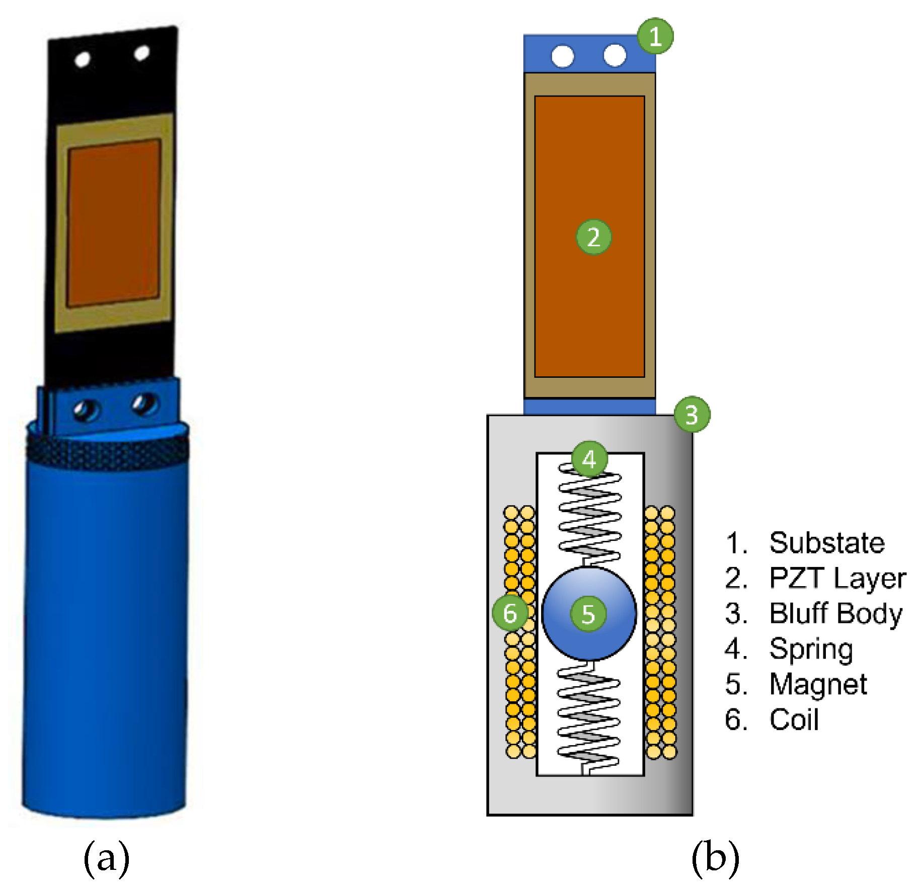
Figure 2.
Harvester equivalent lumped-mass model.
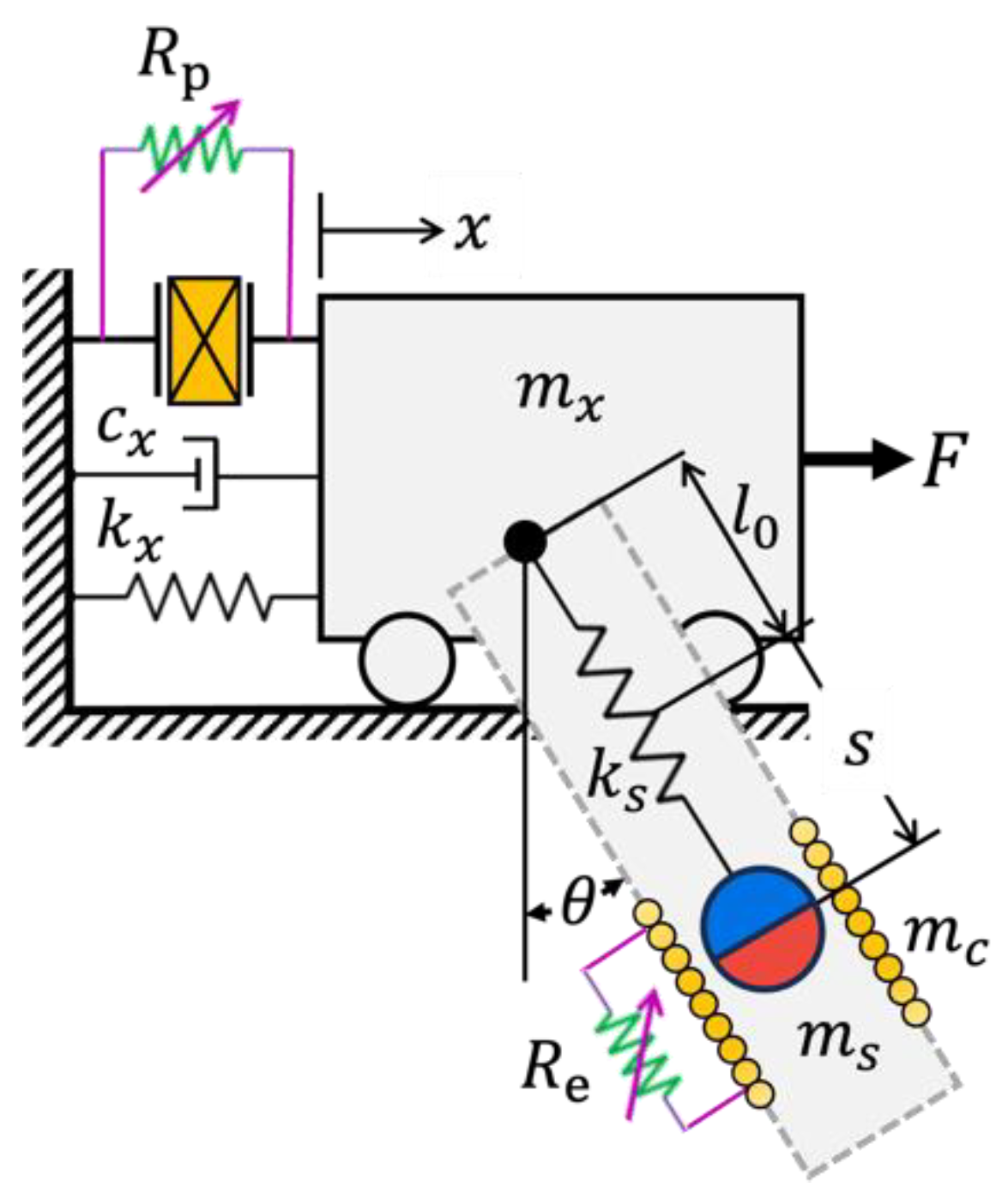
Figure 3.
Amplitude spectrum of the 2-DoF hybrid harvester.
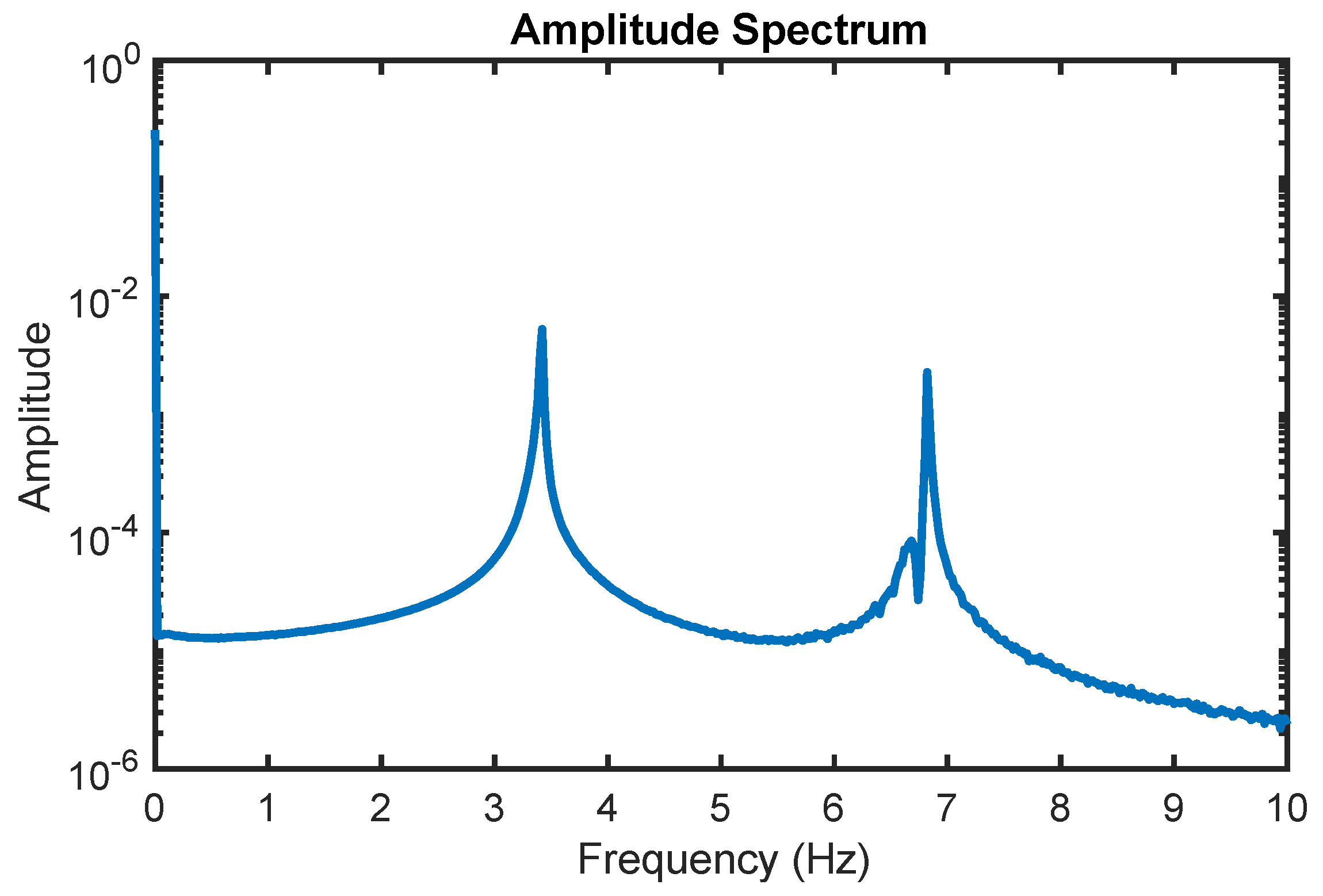
Figure 4.
Electrical output power of the hybrid piezoelectric-electromagnetic harvester.
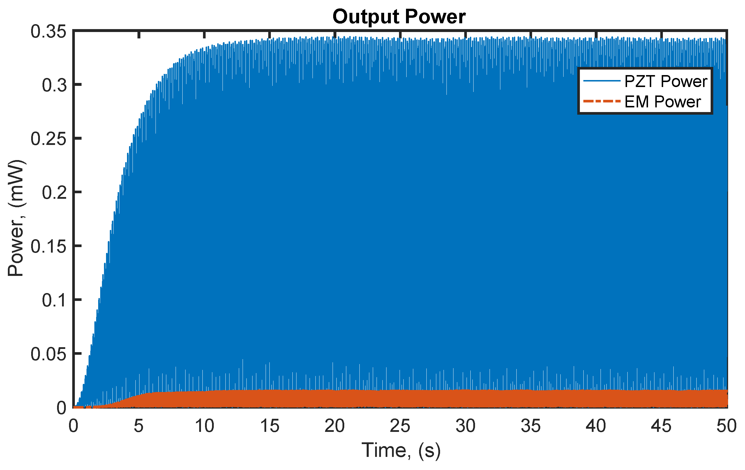
Figure 5.
A comparison between the rms output power of a standalone piezoelectric and hybrid energy harvesters at an optimum external load () of 0.40 MΩ.
Figure 5.
A comparison between the rms output power of a standalone piezoelectric and hybrid energy harvesters at an optimum external load () of 0.40 MΩ.
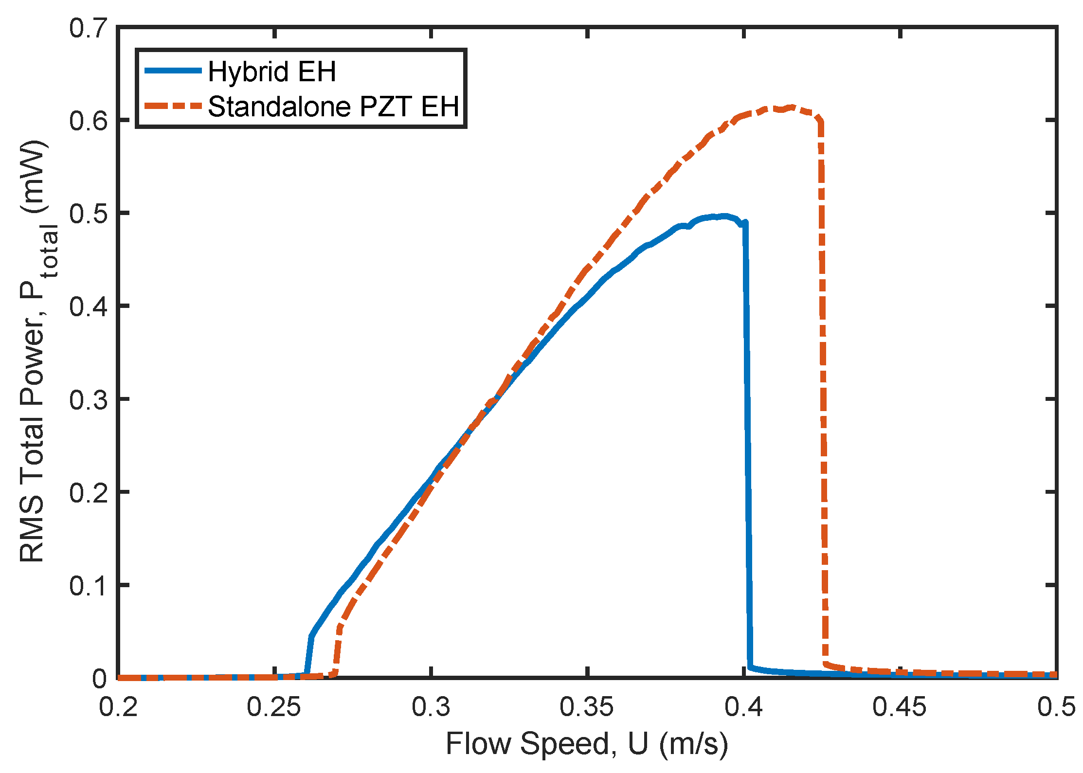
Figure 6.
A comparison between the rms output power of a standalone piezoelectric and hybrid energy harvesters at an external load () of 0.04 MΩ.
Figure 6.
A comparison between the rms output power of a standalone piezoelectric and hybrid energy harvesters at an external load () of 0.04 MΩ.
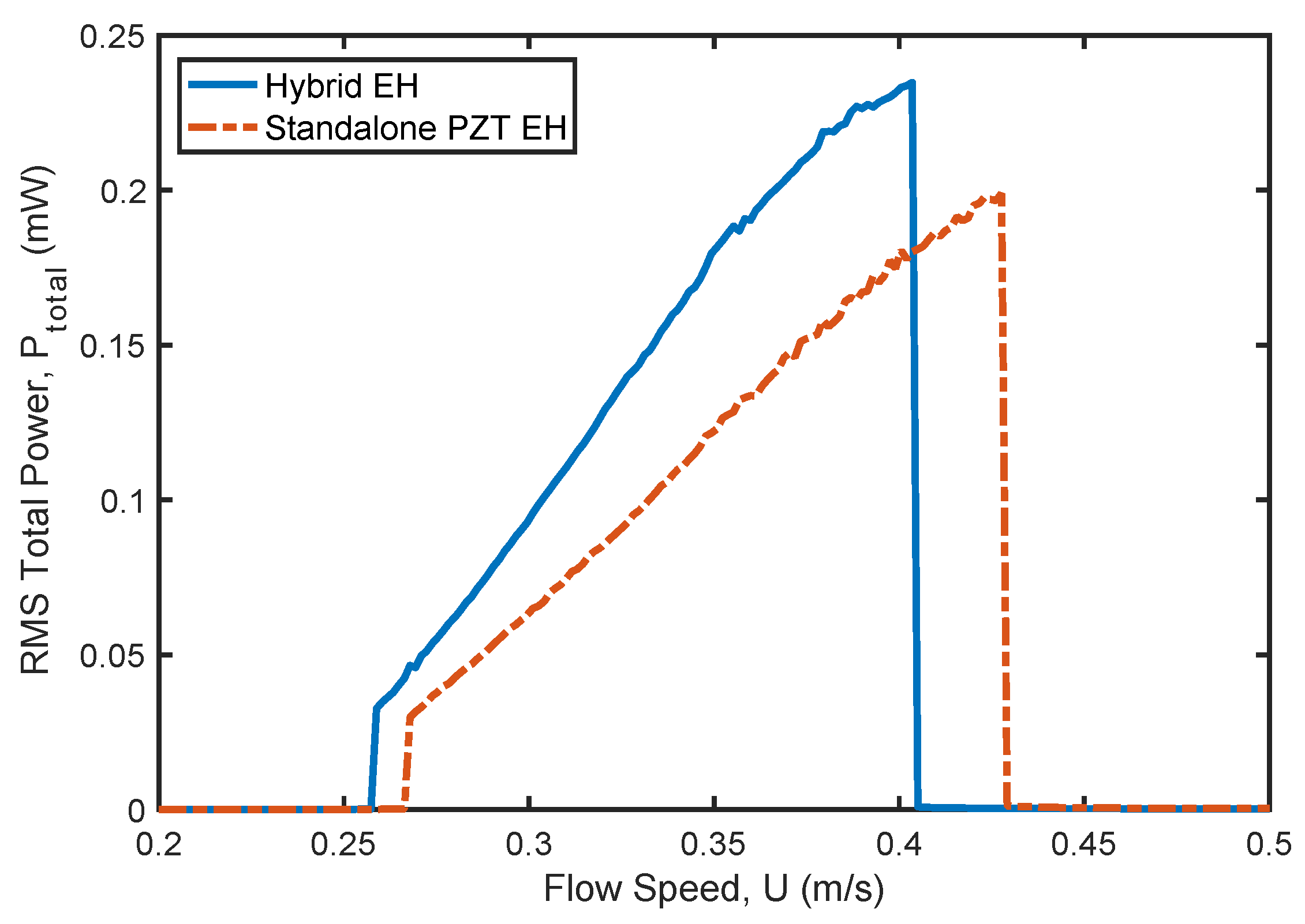
Figure 7.
RMS output power versus spring stiffness of the electromagnetic harvester at flow speed of 0.30 m/s and an external load () of 0.40 MΩ.
Figure 7.
RMS output power versus spring stiffness of the electromagnetic harvester at flow speed of 0.30 m/s and an external load () of 0.40 MΩ.
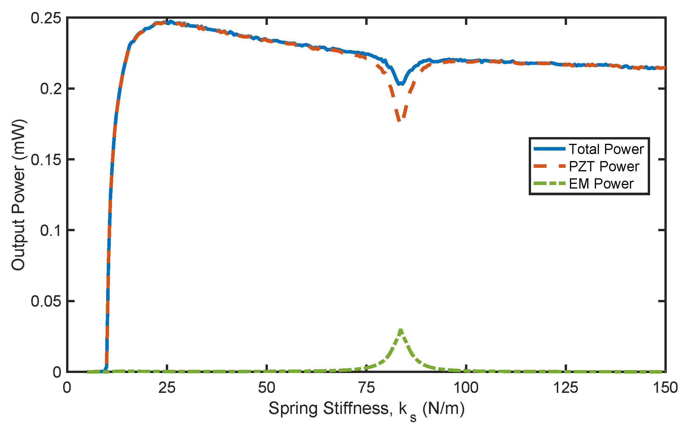
Figure 8.
RMS output power versus spring stiffness of the electromagnetic harvester at flow speed of 0.38 m/s and an external load () of 0.40 MΩ.
Figure 8.
RMS output power versus spring stiffness of the electromagnetic harvester at flow speed of 0.38 m/s and an external load () of 0.40 MΩ.
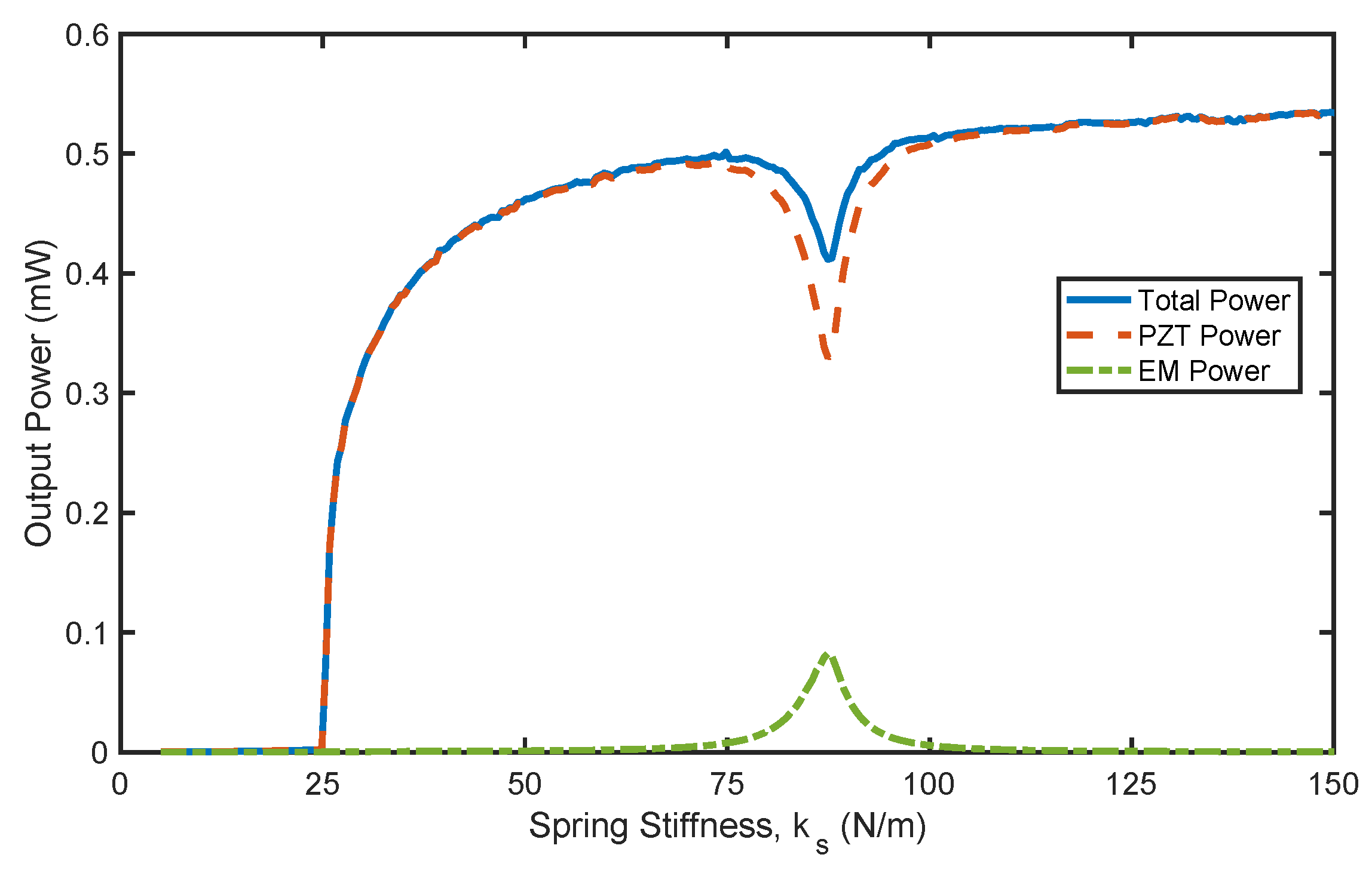
Figure 9.
RMS output power versus spring stiffness of the electromagnetic harvester at flow speed of 0.30 m/s and an external load () of 0.04 MΩ.
Figure 9.
RMS output power versus spring stiffness of the electromagnetic harvester at flow speed of 0.30 m/s and an external load () of 0.04 MΩ.
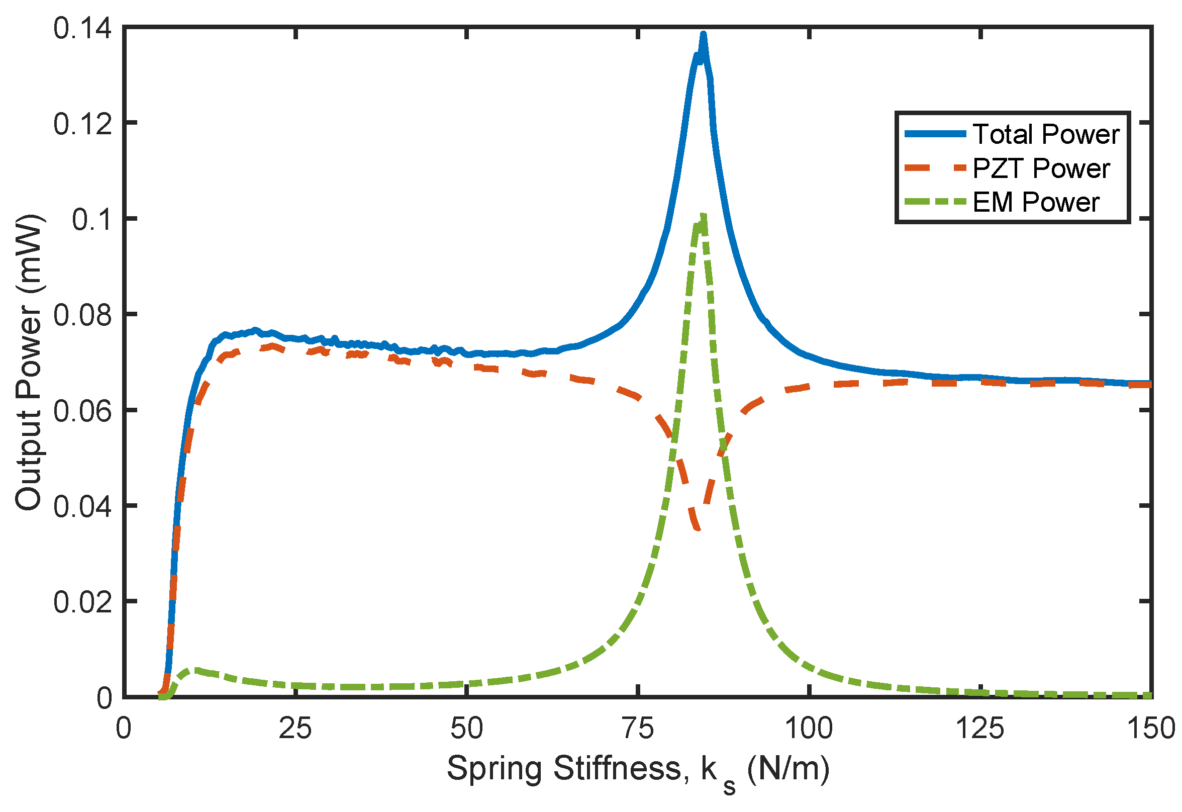
Figure 10.
RMS output power versus spring stiffness of the electromagnetic harvester at flow speed of 0.38 m/s and an external load () of 0.04 MΩ.
Figure 10.
RMS output power versus spring stiffness of the electromagnetic harvester at flow speed of 0.38 m/s and an external load () of 0.04 MΩ.
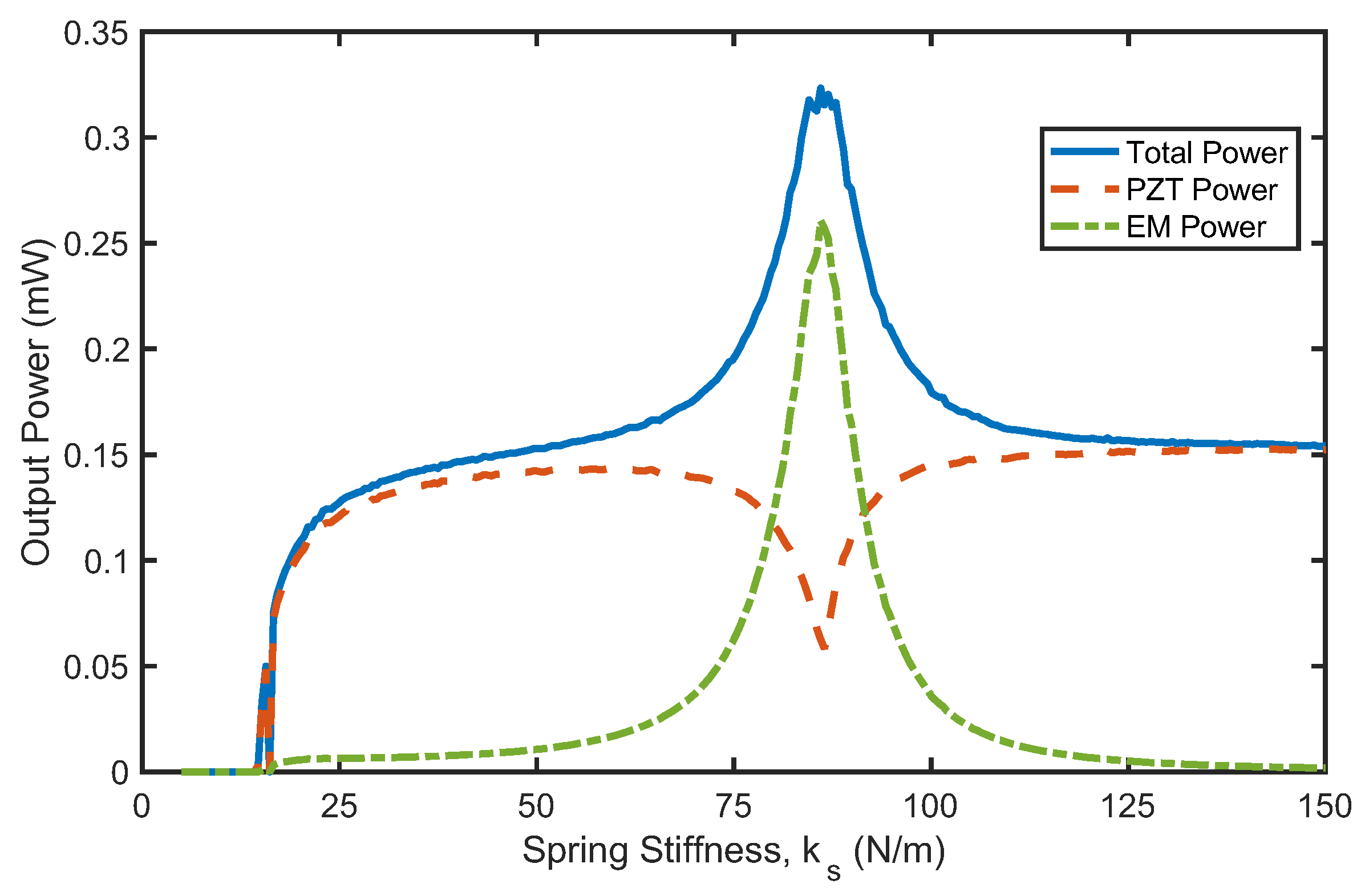

Table 1.
Harvester parameters and material properties.
| Symbol | Description | Value | Unit |
| D | Bluff-body diameter | 21 | mm |
| Bluff body height | 65 | mm | |
| Bluff body mass | 0.0157 | kg | |
| L | Substrate beam length | 70 | mm |
| w | Substrate beam width | 10 | mm |
| h | Substrate beam thickness | 0.5 | mm |
| Substrate beam density | 7800 | kg/m3 | |
| Es | Substrate beam Young’s modulus of elasticity | 71 | GPa |
| Piezoelectric layer density | 7800 | kg/m3 | |
| Ep | Piezoelectric layer Young’s modulus of elasticity (PZT5A) | 61 | GPa |
| Magnetic coil mass | 0.0076 | kg | |
| Coil inductance | 2.7767e-04 | H | |
| Coil resistance | 0.8996 | Ω | |
| Sliding magnet mass | 0.0455 | kg | |
| Electromechanical coupling coefficient | -9.9760e-04 | N/V | |
| Electromagnetic coupling factor | 0.3280 | N/A | |
| Piezoelectric capacitance | 1.2845e-08 | F |
Disclaimer/Publisher’s Note: The statements, opinions and data contained in all publications are solely those of the individual author(s) and contributor(s) and not of MDPI and/or the editor(s). MDPI and/or the editor(s) disclaim responsibility for any injury to people or property resulting from any ideas, methods, instructions or products referred to in the content. |
© 2025 by the authors. Licensee MDPI, Basel, Switzerland. This article is an open access article distributed under the terms and conditions of the Creative Commons Attribution (CC BY) license (http://creativecommons.org/licenses/by/4.0/).
Copyright: This open access article is published under a Creative Commons CC BY 4.0 license, which permit the free download, distribution, and reuse, provided that the author and preprint are cited in any reuse.


