
Submitted:
07 March 2025
Posted:
10 March 2025
You are already at the latest version
Abstract
The shortage of therapists required for the rehabilitation of stroke patients, together with the patients’ lack of motivation in regular therapy, builds the need for a robotic rehabilitation platform. While shared control architectures are studied in literature as means of training, the state-of-art training systems involve a complex architecture and moreover have visible performance limitations. In this paper, a simplified training architecture is proposed, which is particularly targeted for rehabilitation, and also adds the missing features such as complete force feedback, enhanced learning rate, and dynamic monitoring of patient’s performance. In addition to the novel architecture, design of controllers to ensure system stability has been presented. These controllers are analytically shown to meet the performance objectives and maintain system’s passivity. An experimental setup is built to test the architecture and the controllers. A comparison with state-of-art methods is also performed to demonstrate the superiority of the proposed method. It is further demonstrated that the proposed architecture facilitates correcting the inaccurate frequencies at which the patient might operate. This was achieved by defining attribute-wise individual recovery factors to the patient.
Keywords:
Controller Design
; Force Feedback
; Learning Rate
; Multilateral Architecture
; Recovery Factor
; Rehabilitation
; Shared Control
; Stability
1. Introduction
Neurological conditions such as stroke, multiple sclerosis, and Pakinson’s are being a leading cause of long-term disability, with more than 795,000 Americans affected stroke annually (Tsao et al., 2022). Upper extremity hemiparesis, weakness of one side of the body, is one of the most common impairments found in approximately 70% individuals after such neurological conditions (Simpson et al., 2021)(Parker and Snyder-Shall, 1995). The severity of paresis is the primary determinant of functional loss; therefore, rehabilitation is a necessary means to recover motor skills and associated functional skills (Lang et al., 2013). Although high dosage, high intensity, and high repetitions of therapy are all recommended, many patients do not receive the recommended amount of rehabilitation for reasons such as shortage of therapists, and lack of motivation levels (Lang et al., 2009)(Janice et al., 2010).
To accommodate these limitations, a robotic rehabilitation platform is proposed in this paper. In a systematic review of literature, robotic rehabilitation for motor and higher cortical deficits appears to be as effective as in-person therapies (Sarfo et al., 2018). The proposed platform first calibrates the patient using a hand-writing simulator, since hand-writing exercise is a tool commonly used by therapists for recovering upper extremity motions. Based on the assessment of the patient’s initial performance in the hand-writing exercise, he/she is taken to a tele-training session where there are virtual environments to perform daily tasks, and where the patient also receives assistance from the therapist precisely as per his/her need.
For the proposed robotic rehabilitation platform, a multilateral leader-follower architecture with multiple leaders and single follower is adopted. In typical single leader – single follower systems, the leader robot is handled by a human who intends to manipulate objects in an environment. A follower robot, which replicates the motion of the leader robot, is placed in the environment, providing force-feedback to the leader, so that the human gets a ‘transparent’ experience of touching the object (Santiago, Slawiñski and Mut, 2017; Yang et al., 2019).
Extending the leader-follower technology to dual-leader-single-follower (thus moving from bilateral to multilateral) is known for its ability to facilitate training (Cheng and Tavakoli, 2019)(Ryu, Ha-Van and Jafari, 2019), amongst other applications. In the context of rehabilitation, both the therapist and the patient are provided with one leader robot each, and a virtual follower robot is placed in a virtual environment. The therapist makes motions by which patient’s motor skills would be enhanced, and the patient attempts to match the trajectory of the therapist, while looking at the visual feedback on a screen. The virtual robot’s position is controlled on a shared basis by the two leader robots. This approach is technically called as ‘Dual User Shared Control (DUSC)’. The virtual robot sends force-feedback to both the leader robots. Thus, both the therapist and the patient will be able to see the virtual robot interacting with the environment on screen, and will also receive force feedback from the virtual environment.
Researchers have been providing DUSC signal flow architectures for similar training purposes like expert surgeon training a novice and training in car driving. The need for a novel architecture/controller, and the specific objectives of this paper can be appreciated by studying the limitations in state-of-the-art DUSC architectures.
2. Problem Formulation and Literature Review
One of the first works which introduced realizing a haptic training system is reported in (Katsura and Ohnishi, 2006). By controlling force in common mode, and position in differential mode, it was possible to alter the trainer’s assistive forces according to the trainee’s recovery. However, a systematic architecture as well as standard performance objectives for DUSC came up only with (Khademian and Hashtrudi-Zaad, 2012). In this work, a 6-channel architecture was proposed, as shown in Figure 1.
Here and refer to the velocity and force, suffixes , and correspond to human 1 (trainer), human 2 (trainee), and environment, and is the dominance factor. The following are the limitations of this architecture:
- (i)
- Each human operator is receiving only partial force feedback, thus eclipsing her/his realistic experience.
- (ii)
- Transmitting both velocities and forces across all six channels makes it a complex implementation.
- (iii)
- The force exchange between the two leaders is not mandatory. Each human needs to feel the dynamics of others in cooperative task performance(Sun et al., 2019), but not necessarily for the training application.
To overcome some of these limitations, it was proposed in (Shahbazi et al., 2011) that the follower is commanded based on the force inputs of the operators, while the feedback is experienced through the position itself. Although the architecture is now much simplified, it faces some major limitations, as mentioned below.
- (i)
- Transparent experience of the environment is obscured by the robot dynamics when its inertia is high.
- (ii)
- On a similar note, the follower may not reach the desired position when the inertia is high.
An extension of the above work is presented in (Shahbazi et al., 2015), where the follower is given a position-based command, and the operators are given full force-feedback. Yet, it suffers from the following significant limitations:
- (i)
- The system loses its stability because of the additional energy accumulated by the follower, while taking a position input and outputs double the equivalent force.
- (ii)
- This architecture does not send any signal from the trainer to the trainee. The only training is through force feedback from the follower. Thus, the presence of a therapist is not fully utilized.
Variations of the aforementioned architectures can also be found. It is proposed in (Shahbazi, Atashzar and Patel, 2013) that the dominance factor could be time-varying in nature and adapt it as per the patient's recovery. An architecture that introduces two independent dominance factors is presented in (Ghorbanian et al., 2013). All the possible signal transmissions in DUSC are shown in (Tümerdem, 2019). A review of the state-of-art related to DUSC can be found in (Shahbazi, Atashzar and Patel, 2018). It is important to note that none of the architectures except (Khademian and Hashtrudi-Zaad, 2012) provide feedback to the trainer on how well the trainee is performing. This is practically important for the trainer to fine-tune his way of training. More importantly, in all these architectures, the trainee will not be able to get trained in the frequency at which he operates. This limitation is discussed in detail in Section 6 of this paper. The trainee might indeed make an error in various attributes such as amplitude of operation, adding some tremor, frequency mismatch etc. The ideal architecture should be able to correct each of these erroneous attributes of the patient. Thus, there is a need to re-define the manner of computing trainee’s recovery which overcomes such limitations.
While the controllers developed for DUSC are largely classified as pure position controllers (Ghorbanian et al., 2013) or pure force controllers (Khademian and Hashtrudi-zaad, 2008), the training objective demands a hybrid controller and is presented in this work.
Having analyzed the state-of-art and their limitations, the objective of this paper is to propose improved architecture and controllers, specifically for rehabilitation. This involves:
- (i)
- Development of simplified architecture and mathematical notation of the desired objectives
- (ii)
- Ensuring full force feedback to each human
- (iii)
- Giving a measure of patient’s performance to therapist
- (iv)
- Maintaining system stability despite full force feedback
- (v)
- Development of hybrid controllers for the three robots satisfying both the position and force requirements
- (vi)
- Defining a recovery factor for the patient to train them in various attributes, including operating frequency.
The following sections elaborate on these objectives. Section 3 shows the objectives (i)-(iii) being met using a novel architecture. Section 4 shows the development of gain independent, passivity-based controllers, which meet the objectives (iv) and (v), and objective (vi) is shown to be met in Section 6 using an attribute-based recovery factor.
3. Proposed Architecture
The proposed architecture is shown in Figure 2, which provides full feedback to users and allows the therapist to perceive the patient’s performance.
The significance of each of the signals shown in Figure 2 is explained in the following sub-sections.
3.1. Virtual Robot’s Position Tracking
The training process's ultimate objective is that the patient alone should operate the virtual robot accurately. Before the patient attains this recovery level, they are given only partial control over the virtual robot. The degree to which they can be trusted depends on the recovery they have acquired over time. denotes the recovery level of the patient, which is graded on a scale of 0 to 1. The proportion of position command the virtual robot can accept from the patient is directly proportional to this recovery level. Thus, is fed to the virtual robot from the patient. The remaining proportion of comes from the therapist, compensating for the intended motion of the virtual robot.
For brevity, the recovery level is expressed as from now.
When the patient is completely novice, the recovery level is set to zero, thus commanding the virtual robot to take the position of the therapist. As the patient begins to learn, they are assigned a higher recovery level until it reaches unity. In that scenario, the patient can independently manipulate the objects in the virtual environment.
3.2. Full Force Feedback to Users
Since the learning rate can become limited by providing only partial force feedback to each user (traditional architecture – Figure 1), the proposed architecture provides full force feedback to both the therapist and the patient. Mathematically, , where and are the desired forces on the therapist’s robot and the patient’s robot. However, such liberal transmission of force feedback is not free from disadvantages. As explained in Section 2, giving excess net feedback tends to make the system unstable. The means of overcoming this instability is shown in Section 4.
3.3. Learning Experience for the Patient
The patient controlling the virtual robot and receiving force feedback does not necessarily ensure their learning from the therapist. To make full utility of an expert therapist's presence, it is to be ensured that the patient also feels the motions the therapist makes through an ‘assistive signal.’ A fraction of is thus required to be sent for the patient to get some help from the therapist, but also not completely being forced by the therapist. The fraction is a function of the instantaneous recovery level of the patient, , since a higher would necessitate lesser assistance. Thus, the patient’s robot is commanded an assistive signal of , where a handle of is still available for the therapist in case a fine-tuning is needed depending on the specific patient and/or task.
3.4. Providing a Measure of Learning to the Therapist
The signals described in Section 3.1, Section 3.2 and Section 3.3 are self-sufficient to serve the training purpose, but careful introspection shows that the therapist is not given a measure (apart from visual feedback) of how well the patient is adapting to the training offered. Thus, the therapist could be teaching any patient in the same manner, without knowledge of the specific strengths and weaknesses of the specific patient. Hence, a function of the recovery factor which can be provided as a measure of patient’s performance is identified here.
The patient’s lack of recovery is reflected in erroneous motion in the virtual robot. When the patient is completely recovered (ideal case), they make the same motion as the therapist, i.e., , resulting in the virtual robot’s position of . However, while , the deviation in from results in the virtual robot’s position not being equal to . The resulting error in the virtual robot position can be understood as shown in Table 1.
Considering the ideal case as the completely recovered situation, the resulting error (say ) in the position of virtual robot can be calculated as,
Thus, the error term shown in (2) being a function of the recovery factor can be utilized to make the therapist realize the performance of the patient.
Since sending back and then computing the error would demand one more channel, it is proposed that the error be computed by sending back to the therapist’s robot. The error term can then be computed as the difference between the therapist’s position and the measured virtual robot’s position. This would not demand an additional channel since the force feedback signal is already being sent from the virtual robot to the therapist. Such minimization of the number of channels indeed reduce the complexity of patient’s controller.
In summary, the following features have been achieved through the proposed architecture shown in Figure 2:
- (i)
- Recovery-based authority for both the operators upon the virtual robot
- (ii)
- Full force feedback to each operator
- (iii)
- An effective learning experience for the patient through an appropriate assistive signal from the therapist
- (iv)
- An estimate of patient’s recovery is passed to the therapist
- (v)
- A simplified 5-channel architecture, leading to reduced complexity of the two leader controllers
Based on the proposed architecture, the desired performance objectives can be mathematically expressed as below:
Thus, the first three of the six goals, as mentioned towards the end of Section 2, are met using the proposed architecture.
4. Controller Design
In this section, controllers are developed for each of the three robots, which can meet the desired performance objectives and stabilize the system, as envisaged in objectives (iv) and (v) of this paper. The system dynamics are first presented before presenting the controller design.
4.1. Dynamic Model of Tele-rehabilitation System
The Lagrangian models of the therapist’s robot, patient’s robot, and virtual robot respectively are (Schilling, 2003):
where represents the mass matrix, represents the Coriolis matrix, represents the gravitational vector, represents the joint variables of the robot, and represent the external torque applied by the therapist and patient respectively, represents the external torque from the environment, and , and represent the joint torques of the therapist, patient and virtual robots, respectively. The controllers are now developed using the nonlinear tool of passivity.
4.2. Concept of Passivity
Passivity is an appropriate tool for DUSC since interconnection of multiple passive sub-systems confirms the passivity of the overall system. Passivity is attained here such that it retains stability irrespective of the controller gains, and the following facts (Hatanaka et al., 2015) are utilized:
Lemma 1: A system can be proven as output strictly passive from input to output by finding a positive semi-definite function such that .
Lemma 1 ties in very closely with the traditional way of proving Lyapunov stability. The gap is bridged by making use of zero-state observability of the system.
Definition 1: A system is zero-state observable if is the only set of states satisfying as long as .
Finally, the relation between passivity and asymptotic stability is stated by the following theorem.
Theorem 1: For a system that is output-strictly passive and zero-state observable, if the storage function is radially unbounded, then the origin is also globally asymptotically stable.
Though not exactly the same, the underlying form of the controllers is derived for DUSC based on the prior work of robotic rehabilitation (Harris et al., 2024).
4.3. Virtual Robot’s Position Controller
As mentioned in Section 3.2, the stability of the virtual robot is at stake because of giving full force feedback to both the operators. Thus, the crucial part of controller design is for the virtual robot. The controller shown in (7) is proposed as the virtual robot’s controller for the proposed architecture.
where
When the controller in (7) is incorporated into the virtual robot dynamics shown in (6), the modified dynamics of the virtual robot are given by,
where refers to the identity matrix. Let denote the position tracking error term of the virtual robot, .
Using (9), modified dynamics (8) can be re‐written as,
Passivity analysis is carried out on (10) by choosing the positive semi-definite storage and radially unbounded as,
Extracting from (10) into (12),
Robot property of being skew-symmetric ensures reducing to zero. In addition, any vector yielding simplifies (13),
Viewing (14) in light of Lemma 1 proves output strictly passivity from input to output . To further confirm the zero-state observability of the system, these values are set to zero in the modified dynamics shown in (10). This leads to the important result of the state , implying position tracking and zero-state observability of the follower. As the three criteria of Theorem 1 are satisfied, globally asymptotic stability is guaranteed.
4.4. Leader Robots’ Hybrid Controllers
As already mentioned, each of the leader robots has input commands of both position as well as force from the other robots. Thus, a hybrid controller which handles a position reference as well as a force reference is developed for each leader robot. This principle of simultaneous position and force control of robots is validated back in (Raibert and Craig, 1981) and is implemented even till recent applications as portrayed in (Yasin and Simaan, 2021). The proposed controller takes the form shown in (15) for either of the leader robots.
where denotes the part of controller which ensures reaching the desired position and denotes the part of controller which ensures attaining the desired force. Both these terms are expressed in (16).
where , , and denote the dynamic parameters (shown in (4) and (5)) of the corresponding leader robot (therapist / patient, as the case may be), denotes the reference position and refers to the desired torque for the corresponding leader robot, refers to the position tracking error, i.e. . All the torques and joint positions mentioned here are also functions of time, whose indication is omitted in (16) for being concise. Though the controller given by (15) is common to both the leader robots, the difference lies in defining and for each robot.
The key point to note from the proposed architecture shown in Figure 2 is that for both the leader robots, the goal of force tracking is the same, i.e., both the users need to experience the environmental force.
where refers to the environmental torque upon the virtual robot.
On the other hand, the reference position signal for both the leader robots differs significantly, as can be seen from Figure 2. Thus, the term can be expressed as and for the therapist and the patient’s leader robots respectively as shown in (18).
Thus, the controllers for both the leader robots, which satisfy the requirements of the proposed architecture, are completely described. To analytically verify the stability of the system with the incorporation of the proposed leader controllers, passivity analysis is performed as portrayed in sub-section 4.3. For brevity, the choice of storage function alone is shown here, and proof of stability is similar to the detailed proof shown in the case of the virtual robot controller.
In summary, the following have been achieved in this Section:
- (i)
- Developed a pure position controller for the virtual robot, and a hybrid position-force controller for both the leaders
- (ii)
- Maintain system stability irrespective of gains
- (iii)
- Meet the proposed architecture’s position and force tracking requirements
Thus, the first 5 of the 6 goals of this paper as stated towards the end of Section 2 have been met.
5. Experiments
The robots used for validating the proposed architecture and controllers are the 3D Systems® Touch Devices, which are particularly known for their force-feedback ability. The Touch device being a 6 Degrees of Freedom (DOF) robot engages proximal muscles of the upper extremity in addition to distal muscles as a result of the reaching movement required to handle the robot (Naider-Steinhart and Katz-Leurer, 2007; Wagner et al., 2007). Movements of the hand are carried out by activation of muscles from the shoulder to the forearm and wrist. The device’s ability to render haptic feedback up to is a sufficient threshold during rehabilitation tasks mentioned here. Each of such devices are provided to the therapist as well as the patient, both of whom can visualize their movements on a screen in front of them (Figure 3).
Each robot is connected to the computer through Unity© Software Interface, which enables the users to perceive the real-time visualization of the robots. The rehabilitation is performed in two stages – the calibration session and the training session. The role of each session is briefly depicted in Figure 4, and is further detailed in the following sub-sections.
5.1. Calibration Session
The primary purpose of the calibration session is to analyze the patient’s abilities in a completely untrained condition. In this session, there are no obstacles placed in the environment, and no training features such as assistive force from the therapist are incorporated. Hand-writing exercises are recommended during rehabilitation of the hemiparetic upper extremity in mildly impaired patients after a stroke to address the impacted dexterity skills (Israely and Carmeli, 2017). Therefore, the calibration is done through a hand-writing exercise, where the patient attempts to follow a reference trajectory only through the visual feedback on the screen. The reference trajectory is either chosen by the therapist from a set of pre-defined symbols/alphabets, or drawn by the therapist manually. In either case, the therapist ensures that the reference trajectory has a mixture of smooth curvatures as well as sharp corners. Such a trajectory would enable to accurately study the degree of patient’s disabled motor skills. The patient attempting to follow a pre-defined reference trajectory, as seen in Unity visualization, is shown in Figure 5.
The error which the patient makes depends on the nature of the reference trajectories, i.e., whether it has smooth curves (as in alphabets “O”, “U” etc.), or has sharp corners (as in alphabets “A”, “M” etc.). In order to get a complete perception of the patient’s motor skills, each pre-defined trajectory is typically a mixture of these two categories. The average error of the patient is recorded and stored as , indicating the error they makes at zero recovery level. (If needed, the therapist may take the patient through multiple calibration sessions to obtain an average value for ). This value is used in the training session as a baseline to determine the recovery level of the patient. An error of or worse indicates that the patient is still in a completely untrained condition (, and an error of zero indicates a fully recovered condition . Thus, any instantaneous error between zero and is linearly mapped to a recovery level on a scale of using the relation,
The therapist is also given a flexibility to study the patient’s motor skills in 3-D, by generating real-time trajectories, which are closer to the patient’s daily activities. The calibration performed using a 3-D trajectory is shown in Figure 6. The error made by the patient in this calibration is 29.27.
5.2. Training Session
Now that the patient’s abilities are quantitatively assessed through a metric, training is offered to help them recover from that condition. The virtual robot, which was not made use of in the calibration session is introduced in the training session. The virtual robot takes a position based on shared control of the therapist and the patient robots. The weightage depends on the instantaneous recovery level of the patient. In the proposed implementation protocol, the position error of the patient is continuously monitored, and so the recovery level of the patient is also dynamically updated according to the relation shown in (20). Thus, the proportion of the position command which the virtual robot takes from the patient’s robot also varies in real-time.
The training session is carried out in a virtual environment, where the patient has to learn to perform activities of daily living. As a preliminary step, a simple virtual environment is modeled, which has a wall rendering high stiffness forces on the operators. A high-stiffness obstacle is purposely chosen here since stability proven in this case implies stability with lesser stiffness obstacles (Ferraguti et al., 2019). Whenever the virtual robot hits the wall, both the operators would feel the force feedback. The virtual environment and the virtual robot can be understood through Figure 7.
Throughout the session, the patient receives an assistive force from the therapist, whose magnitude is inversely related to the recovery level. This assistive force tends to prevent the patient from going away from the therapist, and its magnitude decreases as the patient approaches closer to the therapist. The computation of the assistive force is done through the following relation, using the Euclidean distance between both the robots and the recovery factor.
The proportionality constant is chosen by the therapist to suit the need of the patient (as discussed in Section 3). In the current experiment, the value of the proportionality constant () is chosen as 0.125. Thus lets one layer of control completely in the hands of the therapist, for them to offer training on a patient-specific basis. A quantitative value of is nonetheless suggested to the therapist, based on the average errors of the patient obtained from each time frame. The implementation protocol of the whole training session is depicted in Figure 8.
The therapist has conducted a preliminary rehabilitation for a duration of 1 minute with the bandwidth of operation being approximately 5 cycles/minute, which is typical for beginners’ rehabilitation. When the proposed architecture (Figure 2) and the proposed controllers (shown in (7) and (15)) are implemented on the system, the Cartesian coordinates of the end-effector (stylus) of both the therapist and the patient’s robots are recorded during the training session. These position values, along with the error in each dimension, are reported in Figure 9.
It is to be noted from Figure 9(d) that the magnitude of error in position values are subsiding as time progresses. This is because of the proposed architecture taking action to enhance the recovery rate of the patient while the therapy is going on. The actual learning rate is reflected through the varying recovery factor, which is reported in Figure 10.
5.2. Inferences from the Results
Growth in recovery: The patient who originally began with a recovery factor/level of zero, was able to reach a recovery level of 0.84 during the 1-minute session. In practice, the therapist actually takes the patient through several of such training sessions, which could eventually be performed for longer durations also. This enables the patient to consistently perform his daily life activities with higher recovery levels than what he began with. The key observation here is the continous growth in recovery, a characteristic which is seldom incorporated in the state-of-art (see Section 2).
Full force feedback: Another significant improvement of the proposed method over the state-of-art is the uncompromised full deliverance of feedback forces to both the therapist and patient. Force sensing plays a key role particularly in medical applications, even up to the point of surgeries (Hadi Hosseinabadi and Salcudean, 2022). In most traditional architectures, the environmental force is fedback in proportion to the recovery factor, but here, total environmental force is fedback to both the users to enable complete and accurate perception of the environment. In order to evaluate this feature, the therapist intentionally hits the wall, which renders a constant force of , at time intervals of and . The forces that the end-effectors (stylus) experienced are shown in Figure 11.
Assistive forces: The forces portrayed here are the effective forces, which is a combination of the assistive force (in case of patient) and the environmental force. It can be seen from Figure 11 that during the environmental collision, both the therapist and the patient’s forces indeed overlap. And the magnitude of the force experienced is same as the force which the virtual wall is modeled to render, irrespective of the recovery factor. At the instants when there is no collision, it can be observed from Figure 11 that the end-effector forces for the therapist are zero, but for the patient are non-zero, indicating the assistive forces, which also decrease as the patient recovers.
Position tracking w.r.t. environment: A further observation can now be made from Figure 9a–c that, during the time interval of collisions, the positions of both these robots remain almost constant. During this collision period, the patient’s stopping position need not exactly be the wall position, since the therapists preferred to give them a full force-feedback even if they have not yet reached a perfection in position tracking.
Stability check: Under normal circumstances, such providing of full force feedback to both the robots as in Figure 11 should have led to instability (Shahbazi et al., 2015). Particularly, handling very stiff environments such as a wall is shown to induce instability (Ferraguti et al., 2019) . But the controllers proposed in (7) and (15) were able to maintain the stability of the system despite full force-feedback and high stiffness environment. The system stability is empirically confirmed by the positions not blowing up during collision.
5.4. Comparison with state-of-art
A standard architecture which is typically and widely used for DUSC applications (Khademian and Hashtrudi-Zaad, 2012) is also incorporated on the same experimental testbed, under the same experimental conditions. The time-varying nature of recovery factor, which was actually missing in this reference literature is added, in order to have a fair comparison with the proposed method. The position errors obtained in this case are as shown in Figure 12.
It is evident that the errors in the case of traditional architecture are unable to converge as significantly as in Figure 9(d). The root mean square errors (RMSE) in positions tabulated for both proposed and traditional architectures also show the superiority of the proposed method. The recovery factor and forces obtained are also reported in Figure 13 and Figure 14 for further analysis.
Although the recovery factor rises quickly even with the traditional architecture, it is unable to cross a threshold of even after multiple attempts by the therapist. It is because of the absence of the efficient assistive force (detailed in Section 3.3) that the recovery level is not improving beyond a limited extent.
As explained before, during the two collisions with the wall each of the humans experience only partial force feedback, highly limiting the perception of the wall. During the first hit, the recovery factor of the patient is about (Figure 13) and thus the force he experienced was only a quarter of (Figure 14). During the second hit, the patient’s recovery fell close to zero, and therefore had almost no perception of the wall. Both the users reported that such an experience severely inhibits the learning rate. This again demonstrates the superiority of the proposed method.
6. Additional Results with Attribute-wise Recovery
Another salient feature which the proposed architecture is capable of achieving is the consideration of ‘attribute-wise recovery’. In the previous section, the computation of recovery level is done such that the error between the therapist and patient eventually reduces. In this section, it will be demonstrated that it is further possible to classify the error into specific attributes such as amplitude, frequency, tremor, etc. The advantage in classifying the error lies in the flexibility to train the patient in specific attributes in which they may need more training. A particular patient might be prone to making errors in his frequency of hand-movements, while others may suffer primarily from adding tremor during their activities. Obtaining an individual recovery factor for each attribute enables them to receive focused training in the specific attribute(s).
6.1. Test Conditions
Although the proposed architecture facilitates such attribute-based recovery factor, as a preliminary step, simulations have been performed to validate the claim. The simulation testbed consists of a simple 1-R manipulator (shown in Figure 15), assigned as the therapist’s robot, patient’s robot and virtual robot.
A link of mass 100g and length 10cm is attached to a rotary joint along the axis perpendicular to the ground. The joint angle from the base is measured in the anti-clockwise direction as . is the external torque applied by the therapist, patient or the environment, depending on the robot under consideration. This is denoted as , and in (4)-(6). In practice, the external torque upon both the leader robots is applied in the form of position inputs from the user, and for the virtual robot it is directly applied in the form of torque from the environment. Thus, the position inputs from the therapist and patient are represented by and respectively. Throughout the simulations, it is assumed that the initial position of all the three robots is
6.2. Attribute-wise Recovery Level
Let the therapist input a sinusoidal position of . The therapist’s amplitude and frequency are the reference amplitude and frequency for the patient. Without any training, the patient tries to replicate this motion with some erroneous amplitude, frequency, and even possibly adding some tremor into the system. Thus, the exogenous input of the patient is modeled as , where and correspond to the amplitude and frequency at which the patient is able to operate their leader robot. is the frequency of the tremor introduced by the patient. In practice, this can be measured by modeling the free hand motion of the patient. For the sake of simulations here, a choice of , is made here, since typically tremor frequency is about 10 times the actual operating frequency ( is chosen as 2 here). is the magnitude of the tremor added to the patient’s leader robot. The recovery attained by the patient with respect to the amplitude, , can be defined as,
The relation shown in (22) effectively normalizes any given amplitude of the patient to a corresponding recovery value in the range of . Similarly, the recovery level with respect to the frequency, and tremor can be written as,
Now that , and the individual recovery factors of the patient are known, the position of the virtual robot can actually be computed as follows:
Thus, by defining explicit recovery factor for each attribute, the position of the virtual robot could be accurately described. By following similar definition as presented in (22), any number of attributes in which the patient requires to improve can be modeled. Each of these recovery levels fall within the range of . The overall recovery of the patient can be expressed as an average of all the individual recovery factors.
A weighted average can be used in (25) if the application demands. The procedure for computing the recovery level with consideration to multiple attributes is summarized through Figure 16.
6.3. Claims and Results
Claim 1: Using the attribute-wise recovery factor, the proposed architecture can even handle scenarios where the patient operates with a different bandwidth (frequency), which leads to a chaotic behavior in the traditional architecture.
To validate this claim, a therapist’s input of and a patient’s initial input of are considered. The resultant position of the virtual robot when implemented with the traditional architecture and proposed architecture are shown in Figure 17. The overall recovery level while taking these readings is 0.4.
It can be readily noted that even when the patient operates at the same amplitude as the therapist, and without any tremor, still, with a minor difference in the frequency of operation, the virtual robot’s (plotted in black) amplitude is also unpredictably affected in case of traditional architecture. But due to the attribute-wise classification, the proposed architecture was able to maintain an averaged amplitude as well as frequency.
Claim 2: Using the attribute-wise recovery factor, the proposed architecture helps the patient to recover in errors much faster than the traditional architecture.
In order to validate this claim, a case study is considered where the patient begins with a different amplitude than the therapist and also adds tremor. With the same therapist’s input as , the patient’s initial input is now taken as . Since the effect of frequency mismatch is already demonstrated through Figure 16, this case study assumes that the patient operates at the same frequency as the therapist, so that a fair comparison could be made between the two architectures. The recovery rates with the above-mentioned inputs are shown in Figure 18.
An observation can be made that with the same test conditions and same initial conditions, the patient could match the therapist’s trajectory in about in the case of proposed architecture, while it takes about to do the same with traditional architecture. This again demonstrates the effect of attribute-wise recovery factor.
7. Conclusions
The concept of dual-leader-single-follower is exploited in this paper to develop a platform for facilitating upper extremity rehabilitation of stroke patients. The proposed architecture allows the therapist and the patient to conjointly control a virtual robot in its environment, while both the humans perceive environmental forces. The recovery of the patient is continuously monitored, and they are provided with a corresponding assistive force from the therapist, to enhance their performance. The controllers developed ensure that the system remains stable (irrespective of gains) and also that the performance objectives (such as position tracking, force perception) are accurately met. A therapist and a patient are allowed to operate on a 6 DoF robotic system, and subsequently found that the architecture and controllers validated. Several features absent in the typical training architectures were incorporated in the proposed architecture and tested on the experimental setup.
Acknowledgements
The authors thank the Jump ARCHES program, which is a collaborative effort between the Health Care Engineering Systems Center, University of Illinois Urbana Champaign, and the OSF Health Care, Peoria, for funding this research, under the grant P-291.
References
- Cheng, L.; Tavakoli, M. A multilateral impedance-controlled system for haptics-enabled surgical training and cooperation in beating-heart surgery. Int. J. Intell. Robot. Appl. 2019, 3, 314–325. [Google Scholar] [CrossRef]
- Ferraguti, F.; Landi, C.T.; Sabattini, L.; Bonfè, M.; Fantuzzi, C.; Secchi, C. A variable admittance control strategy for stable physical human–robot interaction. Int. J. Robot. Res. 2019, 38, 747–765. [Google Scholar] [CrossRef]
- Ghorbanian, A.; Rezaei, S.; Khoogar, A.; Zareinejad, M.; Baghestan, K. A novel control framework for nonlinear time-delayed Dual-master/Single-slave teleoperation. ISA Trans. 2013, 52, 268–277. [Google Scholar] [CrossRef]
- Hosseinabadi, A.H.H.; Salcudean, S.E. Force sensing in robot-assisted keyhole endoscopy: A systematic survey. Int. J. Robot. Res. 2021, 41, 136–162. [Google Scholar] [CrossRef]
- Nisar, H.; Annamraju, S.; Deka, S.A.; Horowitz, A.; Stipanović, D.M. Robotic mirror therapy for stroke rehabilitation through virtual activities of daily living. Comput. Struct. Biotechnol. J. 2024, 24, 126–135. [Google Scholar] [CrossRef] [PubMed]
- Hatanaka, T.; Chopra, N.; Fujita, M.; Spong, M.W. Passivity-Based Control and Estimation in Networked Robotics; Springer Nature: Dordrecht, GX, Netherlands, 2015. [Google Scholar]
- Israely, S.; Carmeli, E. Handwriting performance versus arm forward reach and grasp abilities among post-stroke patients, a case-control study. Top. Stroke Rehabilitation 2016, 24, 1–7. [Google Scholar] [CrossRef]
- Zimbelman, J.L.; Juraschek, S.P.; Zhang, X.; Lin, V.W. Physical Therapy Workforce in the United States: Forecasting Nationwide Shortages. PM&R 2010, 2, 1021–1029. [Google Scholar] [CrossRef]
- Katsura, S.; Ohnishi, K. A Realization of Haptic Training System by Multilateral Control. IEEE Trans. Ind. Electron. 2006, 53, 1935–1942. [Google Scholar] [CrossRef]
- Khademian, B.; Hashtrudi-Zaad, K. A robust multilateral shared controller for dual-user teleoperation systems. 2008 Canadian Conference on Electrical and Computer Engineering - CCECE. LOCATION OF CONFERENCE, CanadaDATE OF CONFERENCE; pp. 001871–001876.
- Khademian, B.; Hashtrudi-Zaad, K. Dual-User Teleoperation Systems: New Multilateral Shared Control Architecture and Kinesthetic Performance Measures. IEEE/ASME Trans. Mechatronics 2011, 17, 895–906. [Google Scholar] [CrossRef]
- Lang, C.E.; Macdonald, J.R.; Reisman, D.S.; Boyd, L.; Kimberley, T.J.; Schindler-Ivens, S.M.; Hornby, T.G.; Ross, S.A.; Scheets, P.L. Observation of Amounts of Movement Practice Provided During Stroke Rehabilitation. Arch. Phys. Med. Rehabil. 2009, 90, 1692–1698. [Google Scholar] [CrossRef]
- Lang, C.E.; Bland, M.D.; Bailey, R.R.; Schaefer, S.Y.; Birkenmeier, R.L. Assessment of upper extremity impairment, function, and activity after stroke: foundations for clinical decision making. J. Hand Ther. 2013, 26, 104–115. [Google Scholar] [CrossRef]
- Li, X.; Pan, Y.; Chen, G.; Yu, H. Multi-modal control scheme for rehabilitation robotic exoskeletons. Int. J. Robot. Res. 2017, 36, 759–777. [Google Scholar] [CrossRef]
- Naider-Steinhart, S.; Katz-Leurer, M. Analysis of Proximal and Distal Muscle Activity During Handwriting Tasks. Am. J. Occup. Ther. 2007, 61, 392–398. [Google Scholar] [CrossRef] [PubMed]
- Parker, M.E.; Snyder-Shall, M. Recovery of Upper Extremity Function in Stroke Patients. Neurol. Rep. 1995, 19, 46–47. [Google Scholar] [CrossRef]
- Raibert, M.H.; Craig, J.J. Hybrid Position/Force Control of Manipulators. J. Dyn. Syst. Meas. Control. 1981, 103, 126–133. [Google Scholar] [CrossRef]
- Ryu, J.-H.; Ha-Van, Q.; Jafari, A. Multilateral Teleoperation Over Communication Time Delay Using the Time-Domain Passivity Approach. IEEE Trans. Control. Syst. Technol. 2019, 28, 2705–2712. [Google Scholar] [CrossRef]
- Santiago, D.D.; Slawiñski, E.; Mut, V.A. Stable Delayed Bilateral Teleoperation of Mobile Manipulators. Asian J. Control. 2017, 19, 1140–1152. [Google Scholar] [CrossRef]
- Sarfo, F.S.; Ulasavets, U.; Opare-Sem, O.K.; Ovbiagele, B. Tele-Rehabilitation after Stroke: An Updated Systematic Review of the Literature. J. Stroke Cerebrovasc. Dis. 2018, 27, 2306–2318. [Google Scholar] [CrossRef] [PubMed]
- Schilling, R.J. (2003) Fundamentals of Robotics: Analysis and Control. New Jersy: Pearson Education.
- Shahbazi, M. , Talebi, H. A., Atashzar, S. F., Towhidkhah, F., Patel, R. V., Shojaei, S. (2011) “A new set of desired objectives for dual-user systems in the presence of unknown communication delay,” in IEEE/ASME International Conference on Advanced Intelligent Mechatronics, AIM, pp. 146–151. [CrossRef]
- Shahbazi, M.; Talebi, H.A.; Atashzar, S.F.; Towhidkhah, F.; Patel, R.V.; Shojaei, S. A new set of desired objectives for dual-user systems in the presence of unknown communication delay. 2011 IEEE/ASME International Conference on Advanced Intelligent Mechatronics (AIM 2011). LOCATION OF CONFERENCE, HungaryDATE OF CONFERENCE; pp. 146–151.
- Shahbazi, M.; Atashzar, S.F.; Talebi, H.A.; Patel, R.V. Novel Cooperative Teleoperation Framework: Multi-Master/Single-Slave System. IEEE/ASME Trans. Mechatronics 2014, 20, 1668–1679. [Google Scholar] [CrossRef]
- Shahbazi, M.; Atashzar, S.F.; Patel, R.V. A dual-user teleoperated system with Virtual Fixtures for robotic surgical training. 2013 IEEE International Conference on Robotics and Automation (ICRA). LOCATION OF CONFERENCE, GermanyDATE OF CONFERENCE; pp. 3639–3644.
- Shahbazi, M.; Atashzar, S.F.; Patel, R.V. A Systematic Review of Multilateral Teleoperation Systems. IEEE Trans. Haptics 2018, 11, 338–356. [Google Scholar] [CrossRef]
- Simpson, L.A.; Hayward, K.S.; McPeake, M.; Field, T.S.; Eng, J.J. Challenges of Estimating Accurate Prevalence of Arm Weakness Early After Stroke. Neurorehabilit. Neural Repair 2021, 35, 871–879. [Google Scholar] [CrossRef]
- Sun, D.; Liao, Q.; Gu, X.; Li, C.; Ren, H. Multilateral Teleoperation With New Cooperative Structure Based on Reconfigurable Robots and Type-2 Fuzzy Logic. IEEE Trans. Cybern. 2018, 49, 2845–2859. [Google Scholar] [CrossRef] [PubMed]
- Tsao, C.W.; Aday, A.W.; Almarzooq, Z.I.; Alonso, A.; Beaton, A.Z.; Bittencourt, M.S.; Boehme, A.K.; Buxton, A.E.; Carson, A.P.; Commodore-Mensah, Y.; et al. Heart Disease and Stroke Statistics—2022 Update: A Report From the American Heart Association. Circulation 2022, 145, E153–E639. [Google Scholar] [CrossRef]
- Tümerdem, U. Three-channel control architecture for multilateral teleoperation under time delay. Turk. J. Electr. Eng. Comput. Sci. 2019, 27, 120–138. [Google Scholar] [CrossRef]
- Wagner, J.M.; Dromerick, A.W.; Sahrmann, S.A.; Lang, C.E. Upper extremity muscle activation during recovery of reaching in subjects with post-stroke hemiparesis. Clin. Neurophysiol. 2006, 118, 164–176. [Google Scholar] [CrossRef] [PubMed]
- Yang, C.; Peng, G.; Cheng, L.; Na, J.; Li, Z. Force Sensorless Admittance Control for Teleoperation of Uncertain Robot Manipulator Using Neural Networks. IEEE Trans. Syst. Man, Cybern. Syst. 2019, 51, 3282–3292. [Google Scholar] [CrossRef]
- Yasin, R.; Simaan, N. Joint-level force sensing for indirect hybrid force/position control of continuum robots with friction. Int. J. Robot. Res. 2020, 40, 764–781. [Google Scholar] [CrossRef]
Figure 1.
Traditional 6-channel DUSC architecture (Khademian and Hashtrudi-Zaad, 2012.)
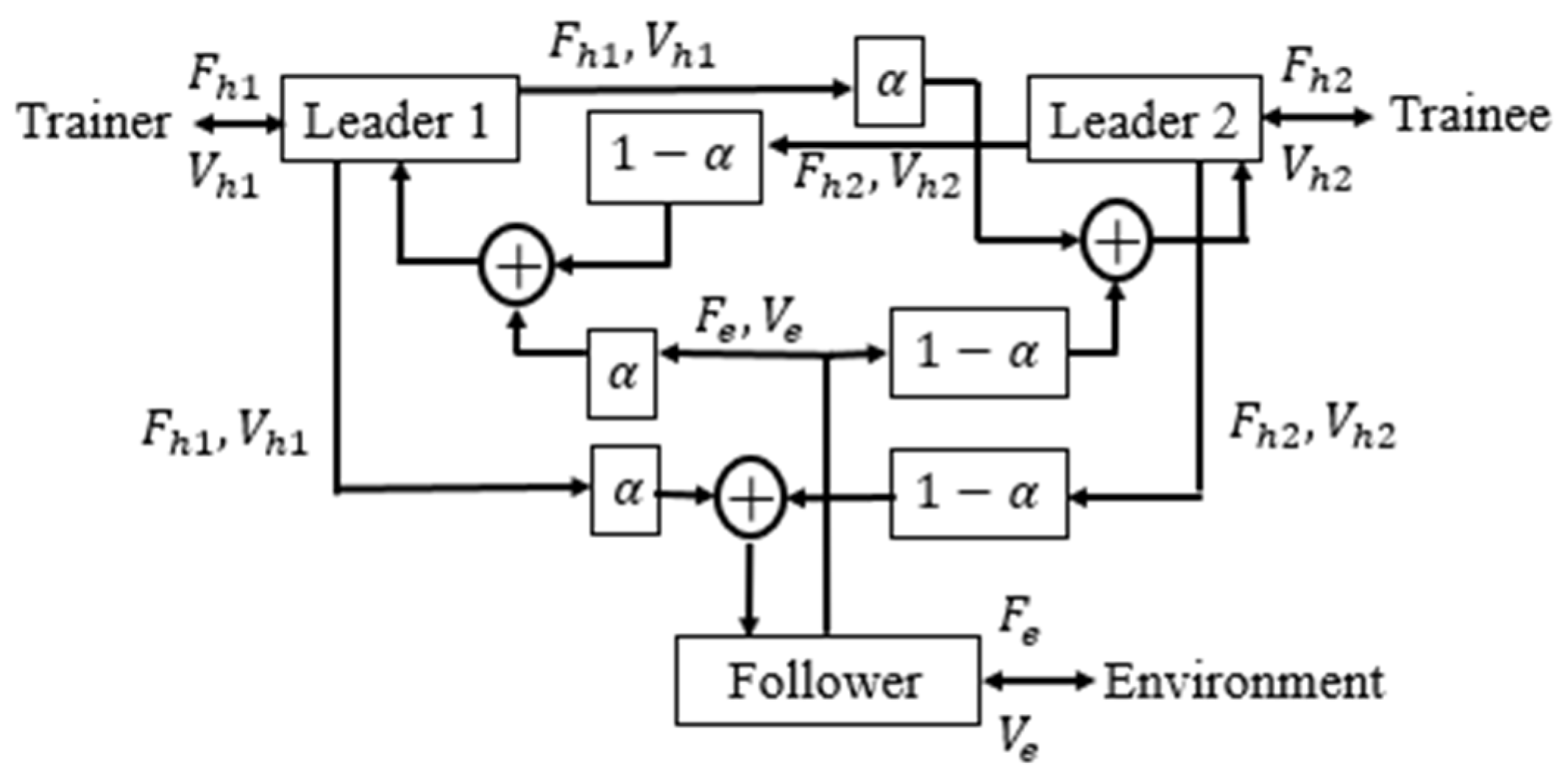
Figure 2.
Proposed Shared Control Architecture for Rehabilitation.
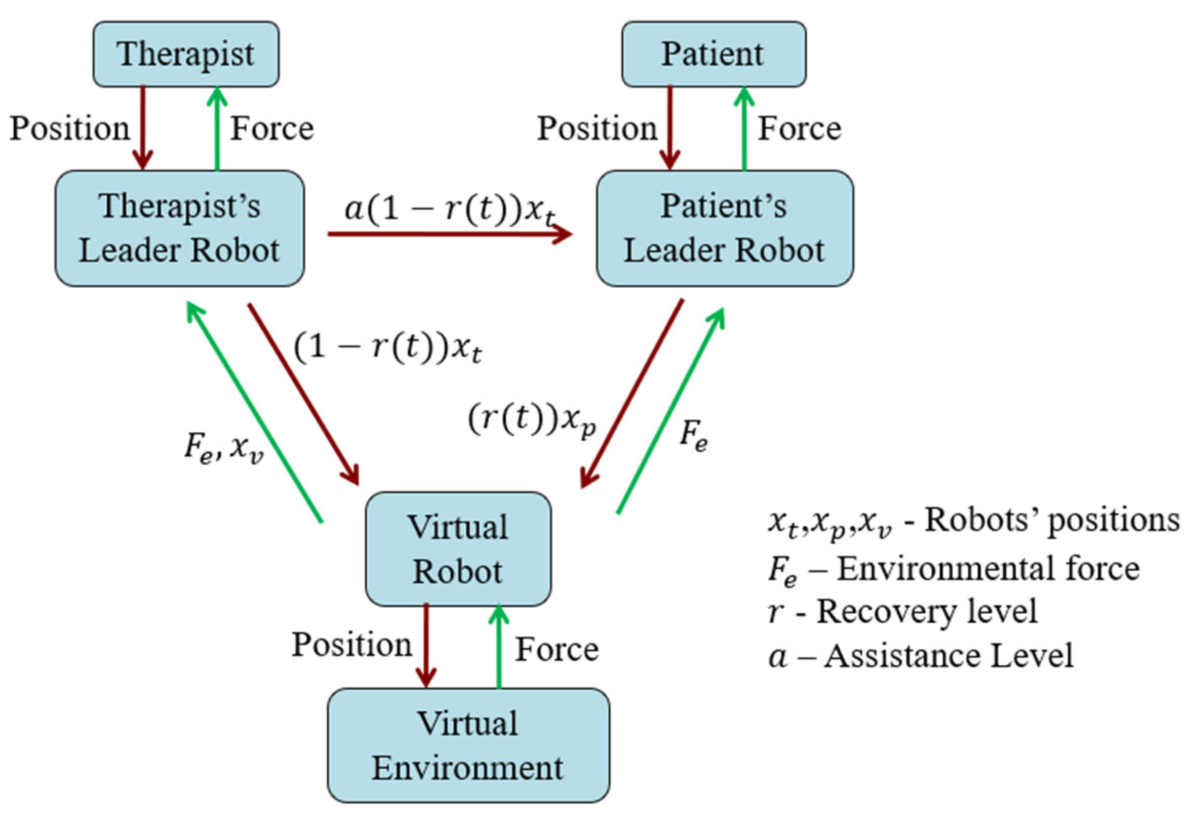
Figure 3.
Robotic Rehabilitation Platform.
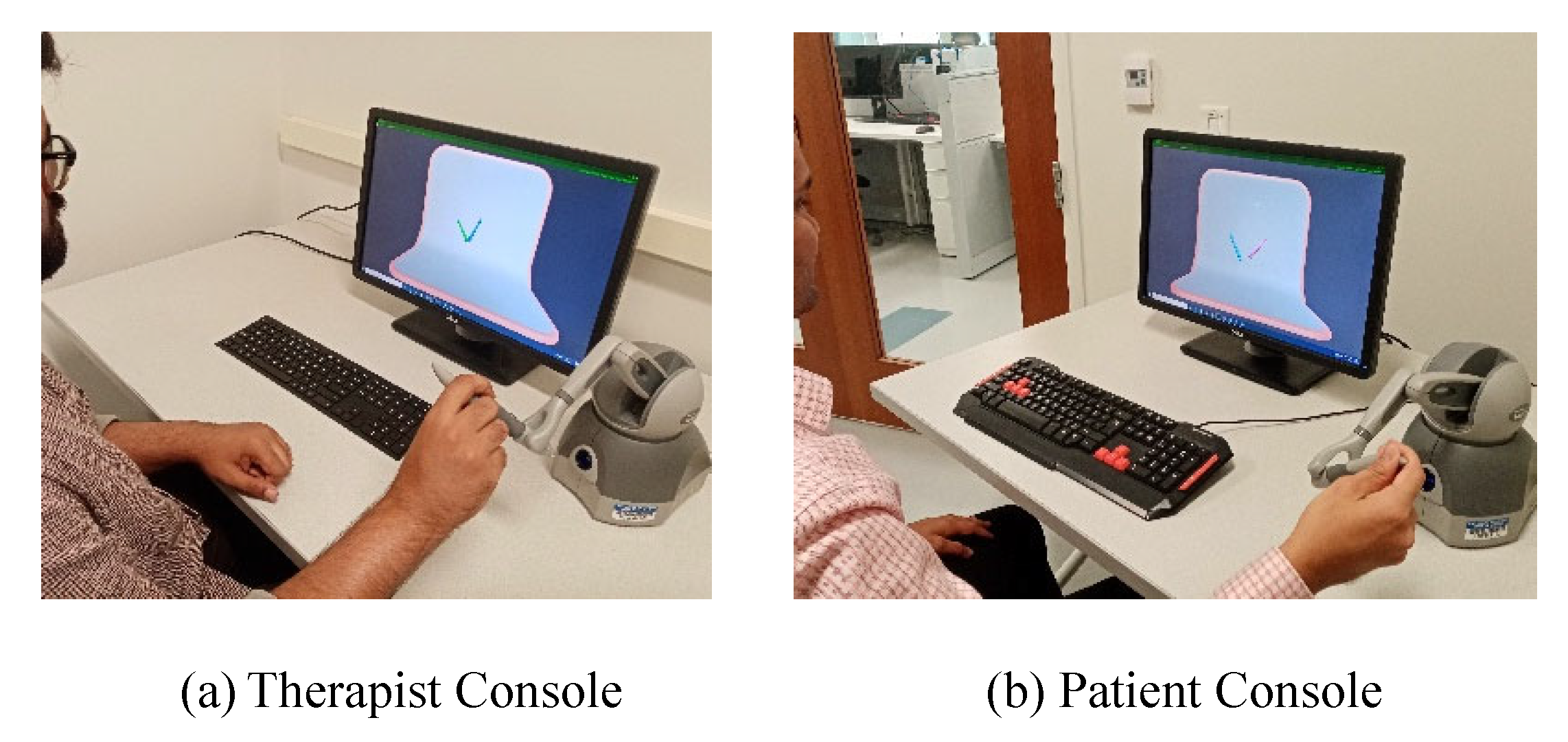
Figure 4.
Features of Calibration and Training Sessions.
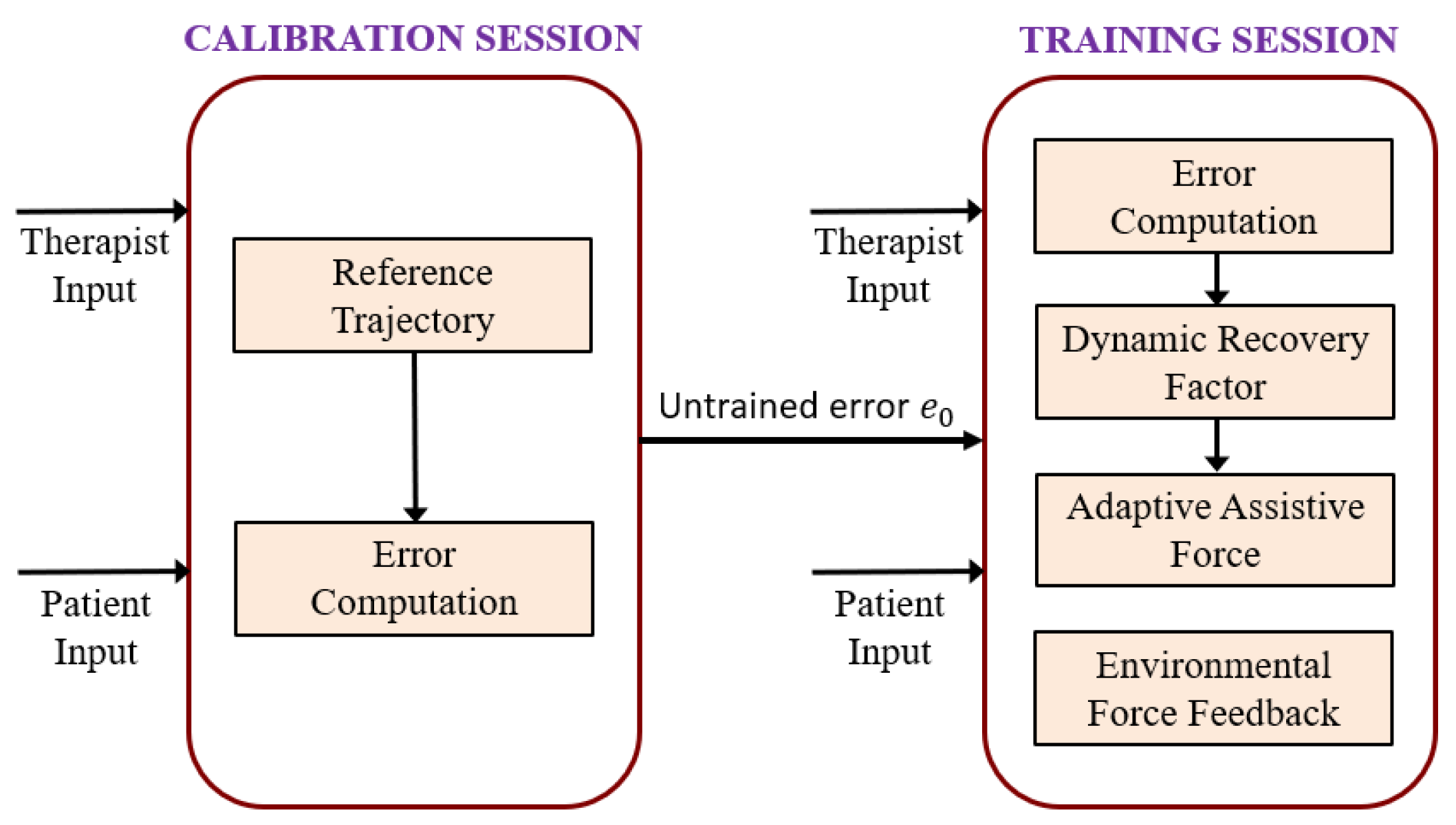
Figure 5.
Unity Visualization of Hand-writing Exercise.
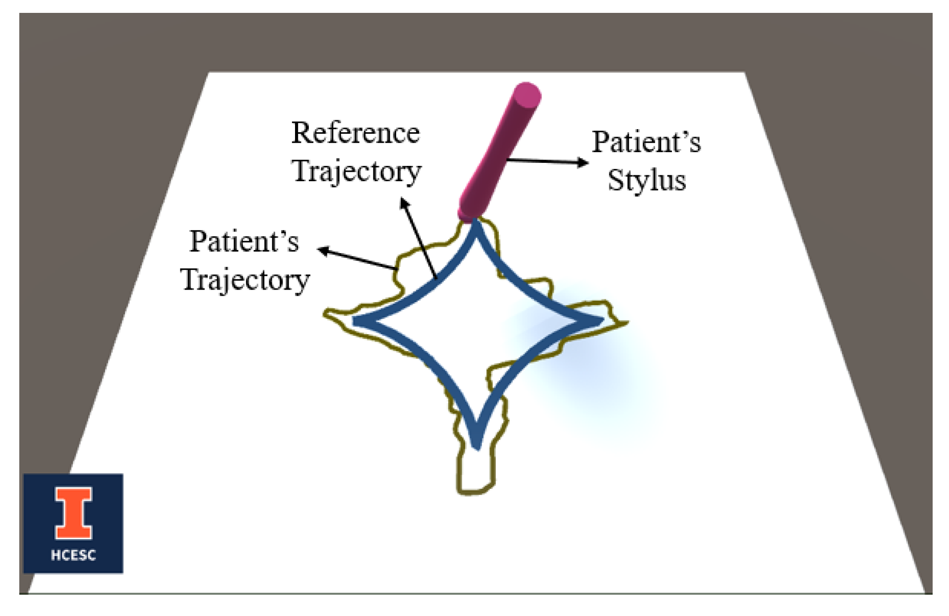
Figure 6.
Unity Visualization of 3-D Position Tracking.
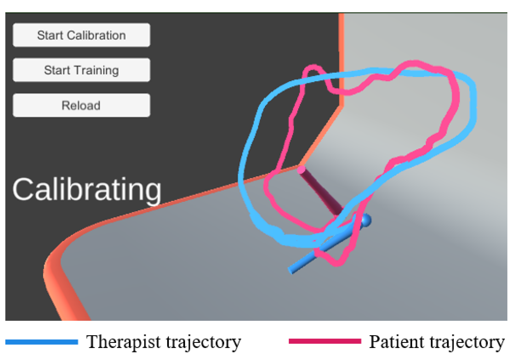
Figure 7.
Training session with virtual environment.
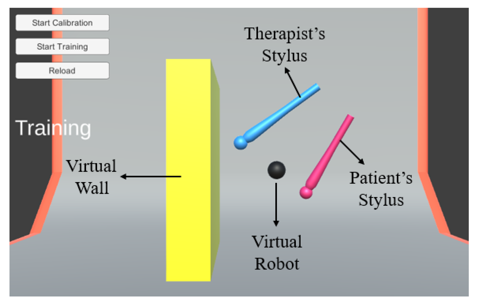
Figure 8.
Implementation Protocol.
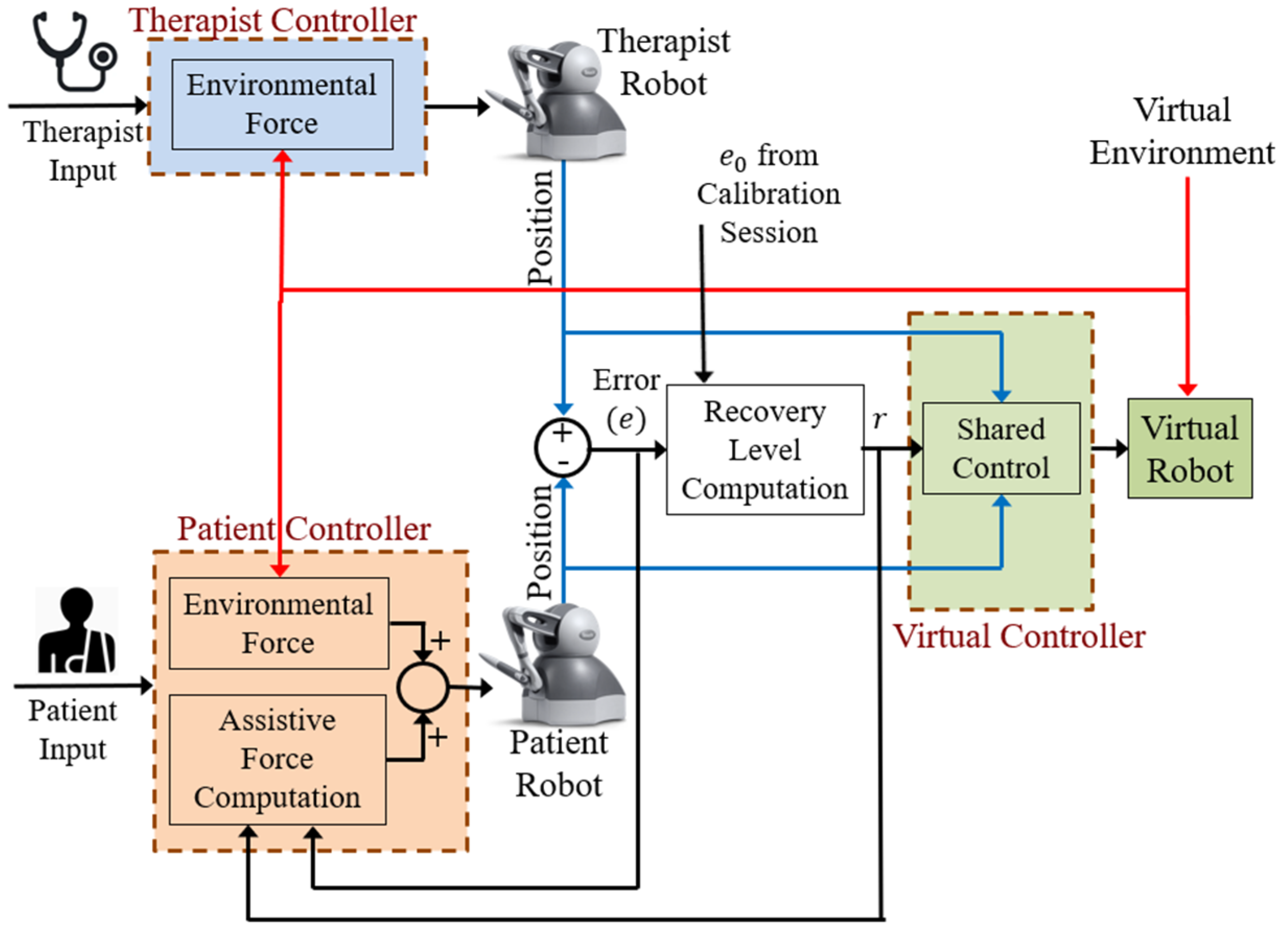
Figure 9.
Positions in Training Session with Proposed Method.
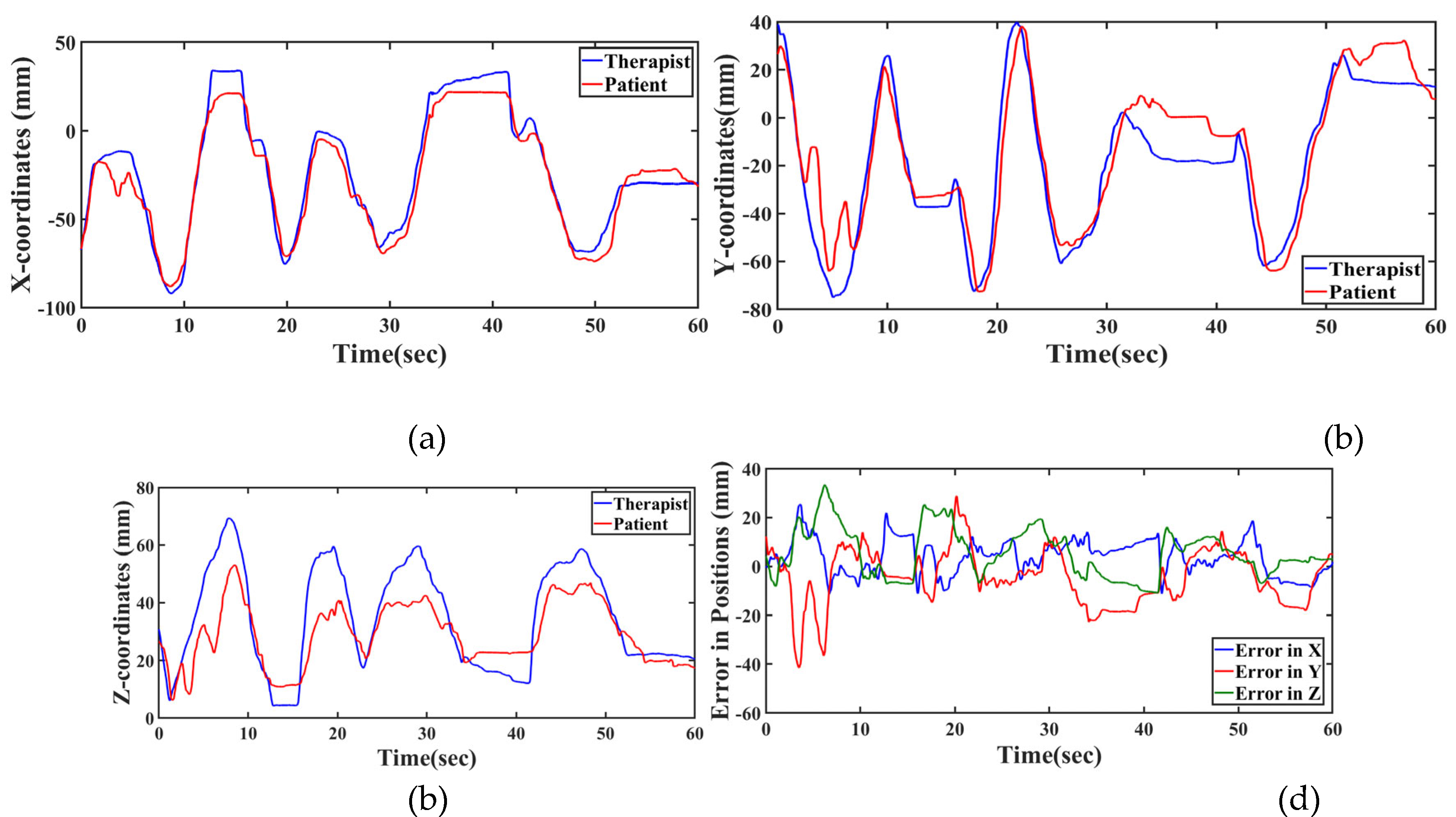
Figure 10.
Recovery factor enhancing with time.
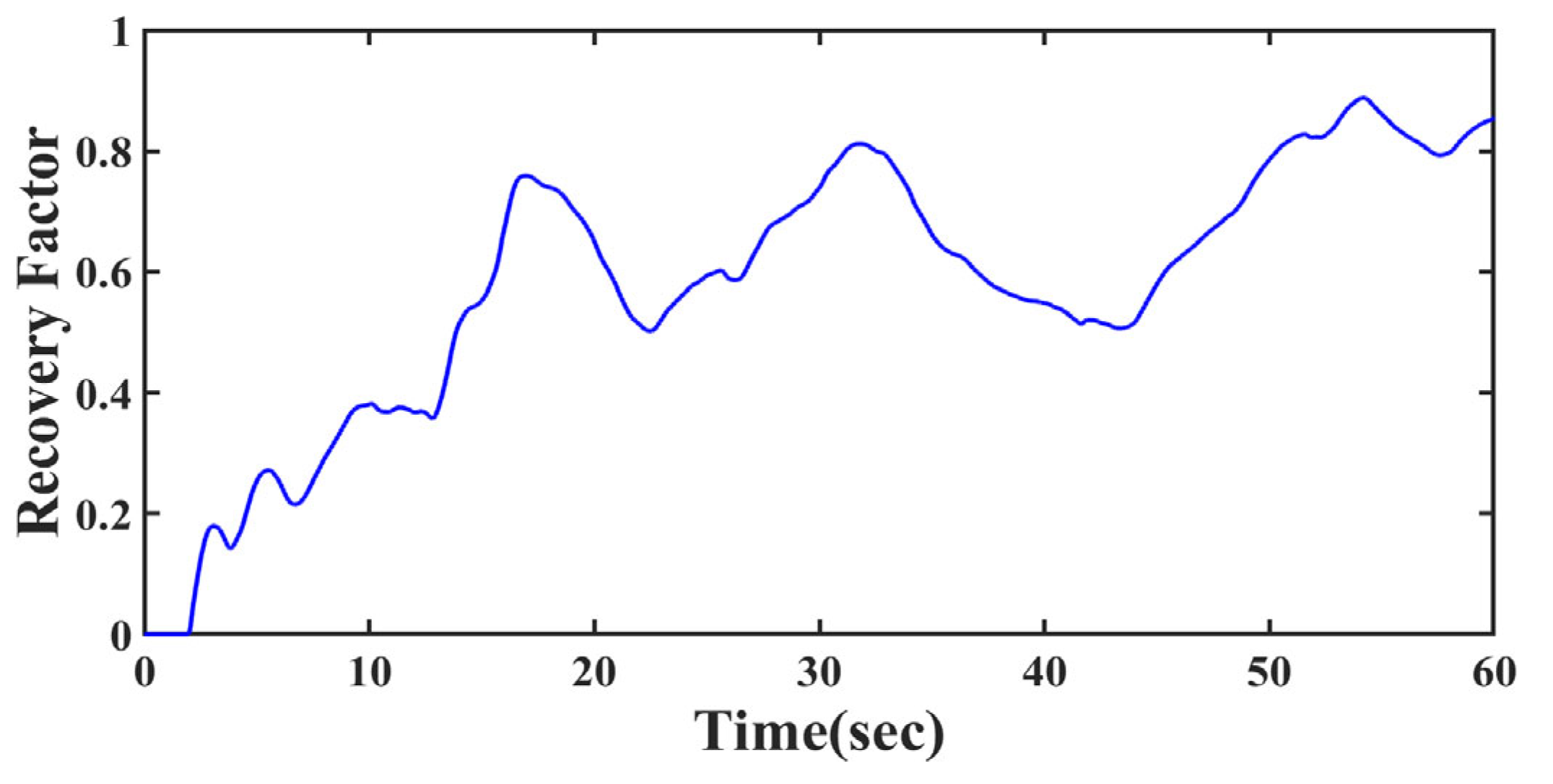
Figure 11.
Forces with Proposed Method
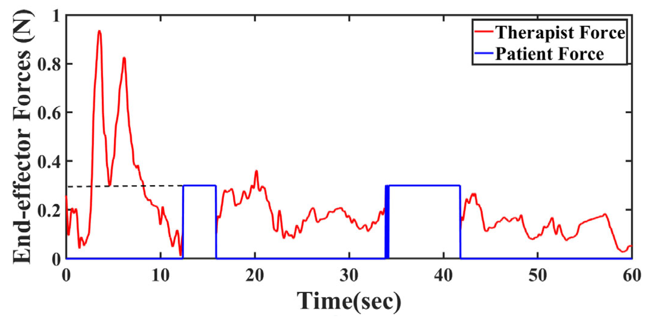
Figure 12.
Position errors with Traditional Architecture, along with RMSE Comparison
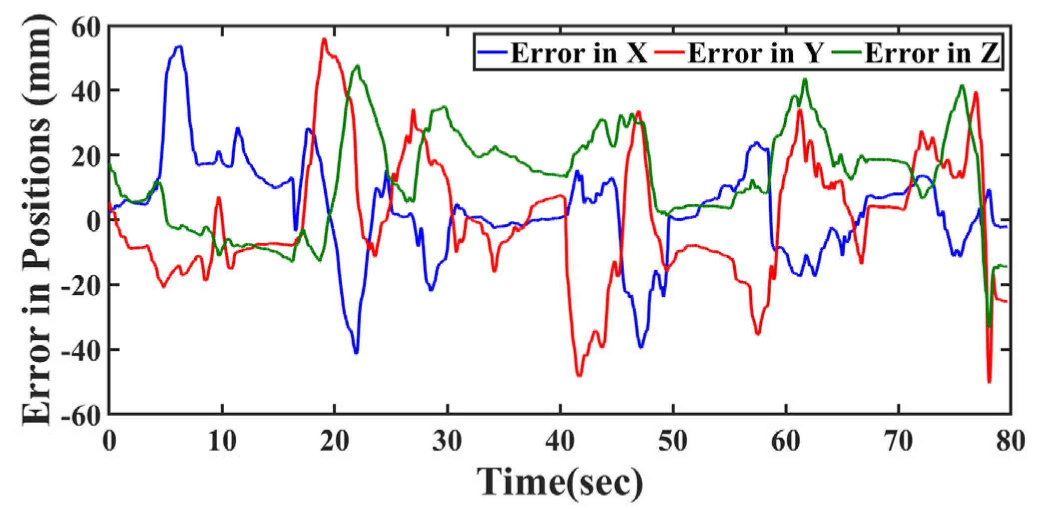
Figure 13.
Recovery factor with Traditional Architecture
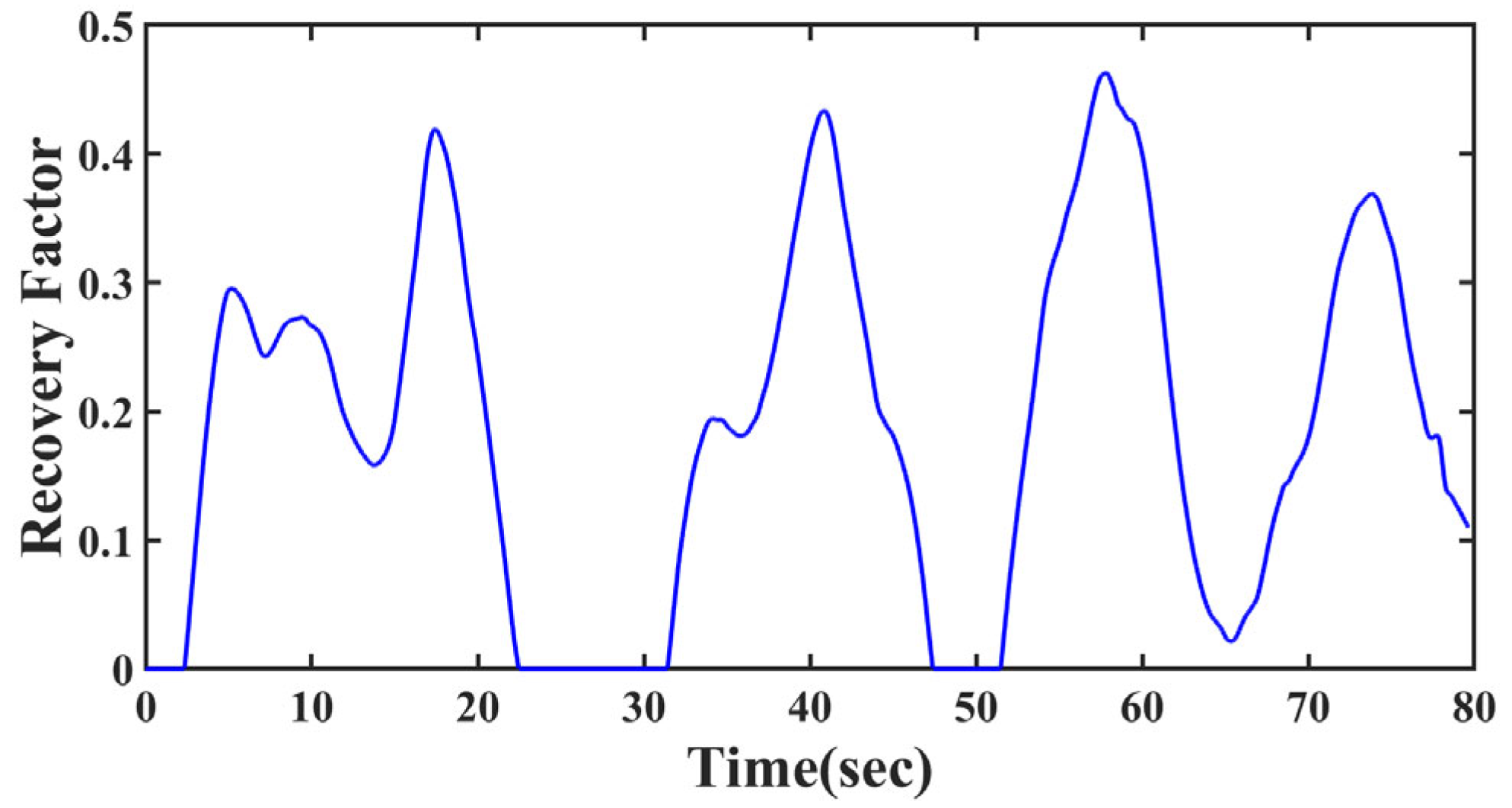
Figure 14.
Forces with Traditional Architecture
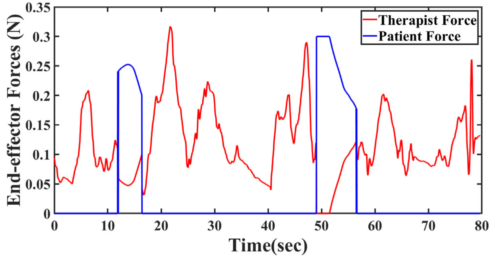
Figure 15.
1-R Manipulator.
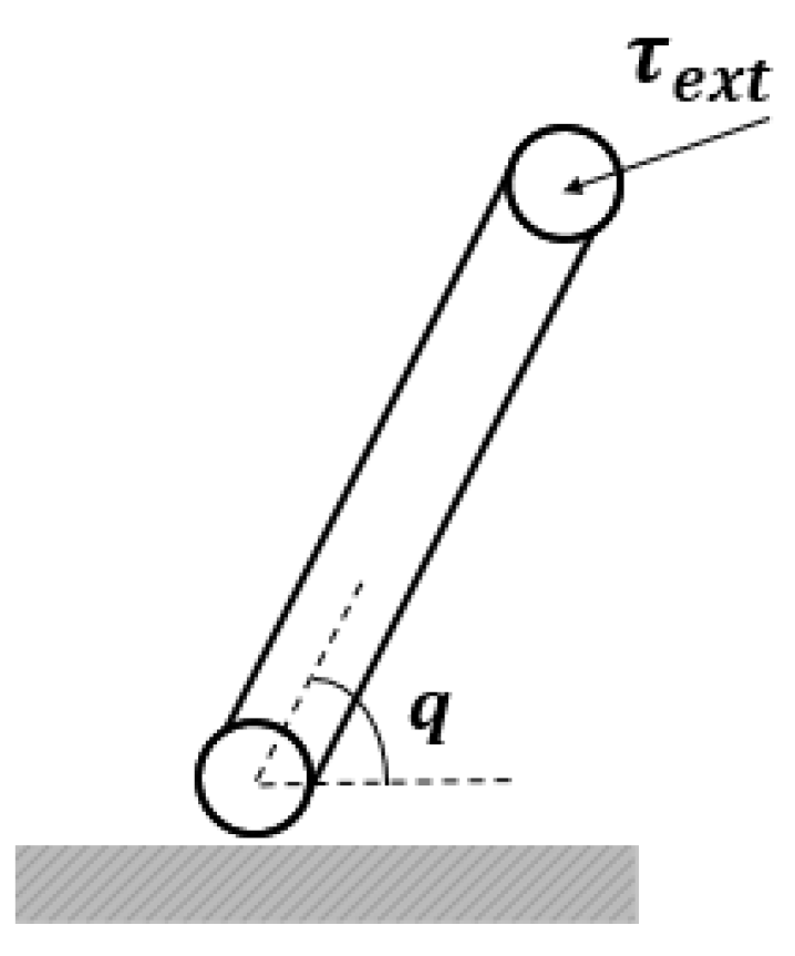
Figure 16.
Computation of Attribute-wise Recovery Level.
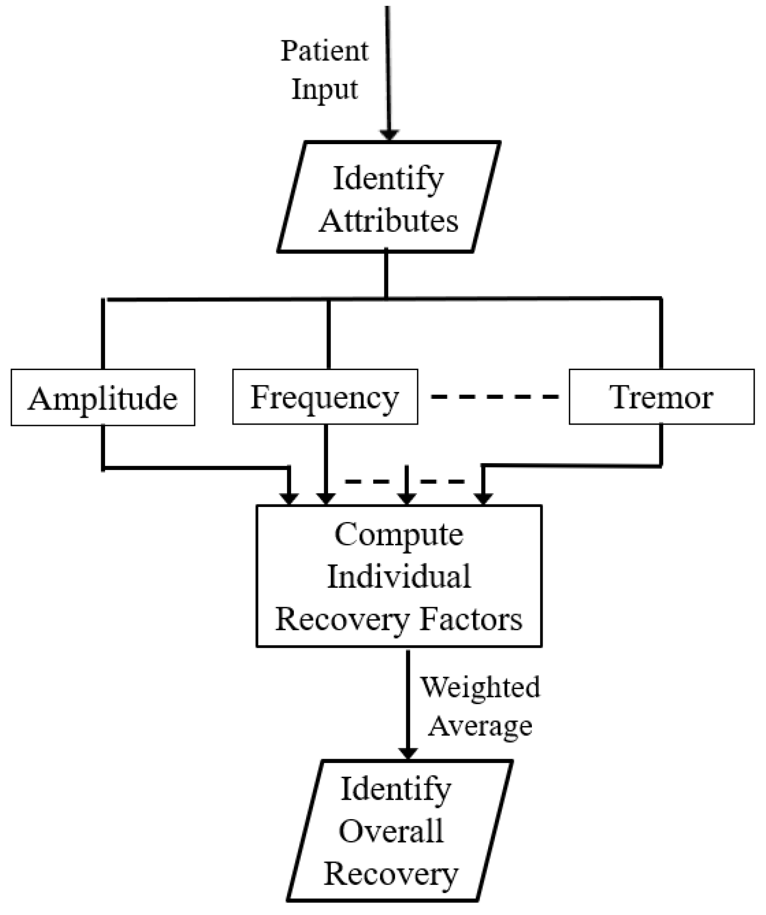
Figure 17.
Analysis of frequency mismatch scenario.
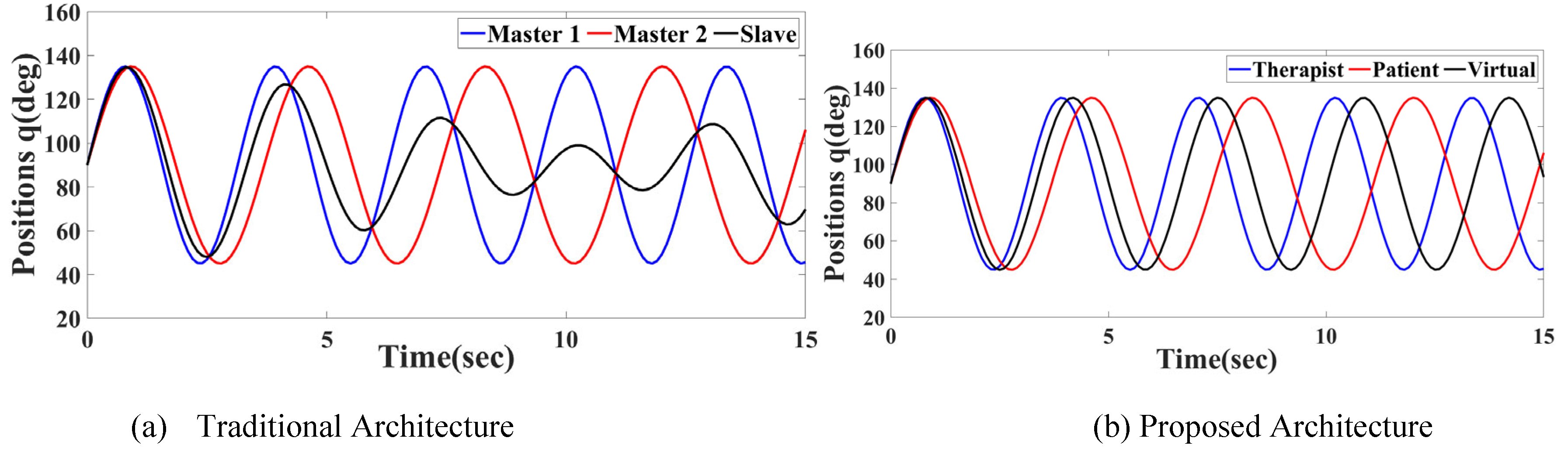
Figure 18.
Comparison of Learning Rate.
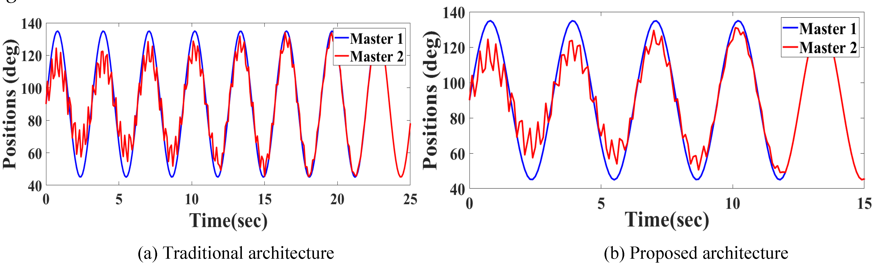

Table 1.
Analysis of learning and trained phases.
| Completely recovered case | =1 | |
| Recovering phase |
Disclaimer/Publisher’s Note: The statements, opinions and data contained in all publications are solely those of the individual author(s) and contributor(s) and not of MDPI and/or the editor(s). MDPI and/or the editor(s) disclaim responsibility for any injury to people or property resulting from any ideas, methods, instructions or products referred to in the content. |
© 2025 by the authors. Licensee MDPI, Basel, Switzerland. This article is an open access article distributed under the terms and conditions of the Creative Commons Attribution (CC BY) license (http://creativecommons.org/licenses/by/4.0/).
Copyright: This open access article is published under a Creative Commons CC BY 4.0 license, which permit the free download, distribution, and reuse, provided that the author and preprint are cited in any reuse.


