Submitted:
11 March 2025
Posted:
12 March 2025
You are already at the latest version
Abstract
At present, Due to a scarcity of power, Pakistan is facing major load shedding and blackout issues. In order to address this issue, renewable energy resources (RESs) may be a suitable option. Pakistan is blessed with many RESs such as solar, wind and hydro. The present energy crisis may be solved suitably if the Pakistan generates electrical power from these RESs. Among these RESs, wind energy is preferable because it is cost-effective and environmentally friendly. Power generated from wind farm can be integrated with grid through voltage source converter (VSC) in order to meet increased load demand. Wind farms commonly use different types of generators; doubly fed induction generator (DFIG) based wind variable speed technology is presently the most often utilized in wind farms, due to its many benefits. This study based on modelling and simulation of 9 MW wind farm based on DFIG using MATLAB/Simulink software version 2020a. The designed wind farm will be integrated with Grid and its performance will be analyzed for various wind speed variation cases in order to show its effectiveness.
Keywords:
1. Introduction
1.1. Main Objectives & Contribution
1.2. Structure of the Article
2. Literature Review
3. Suggested DFIG System Framework and Modeling
3.1. Modelling of Wind Turbine
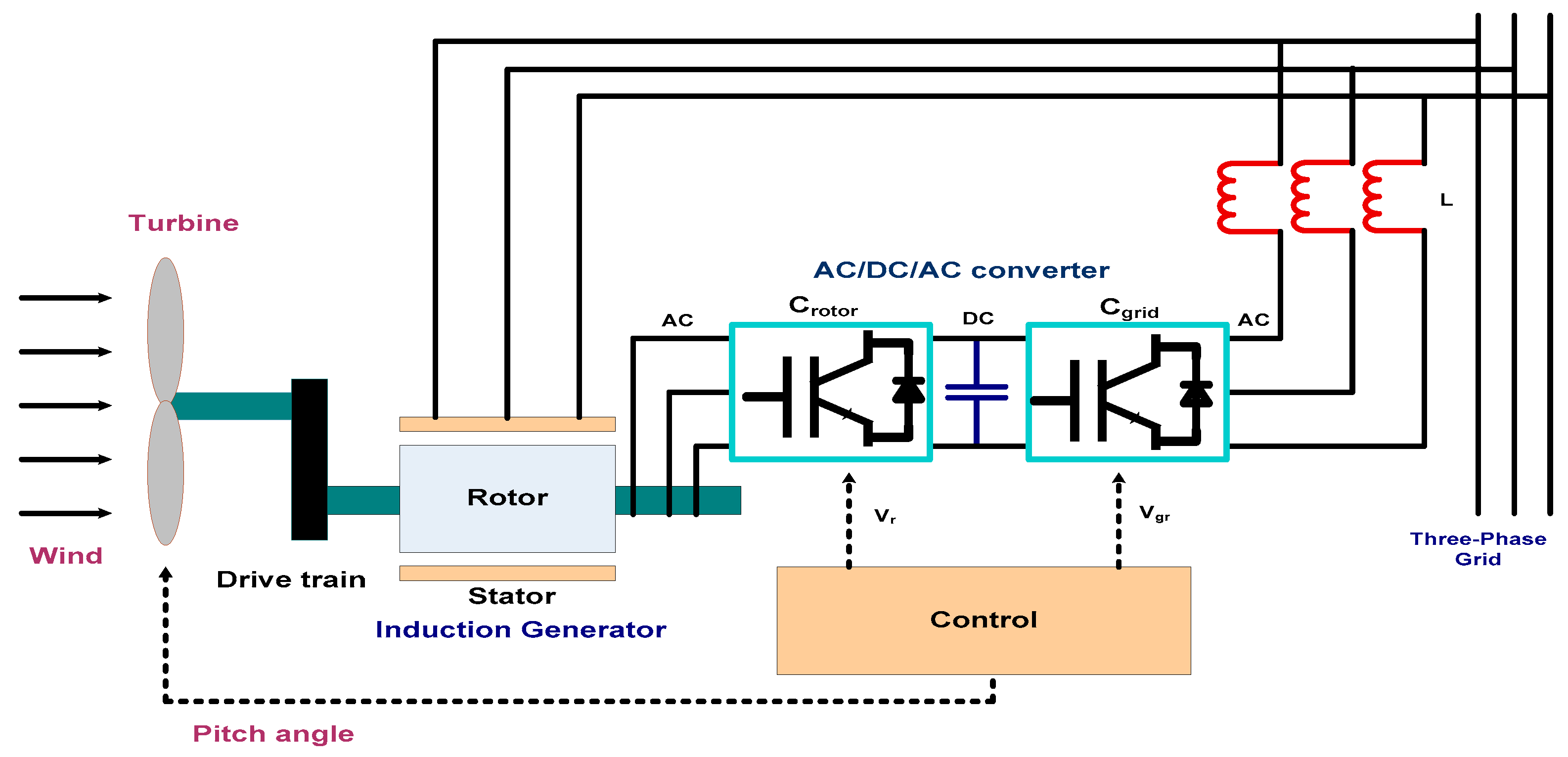
3.2. Modelling of DFIG
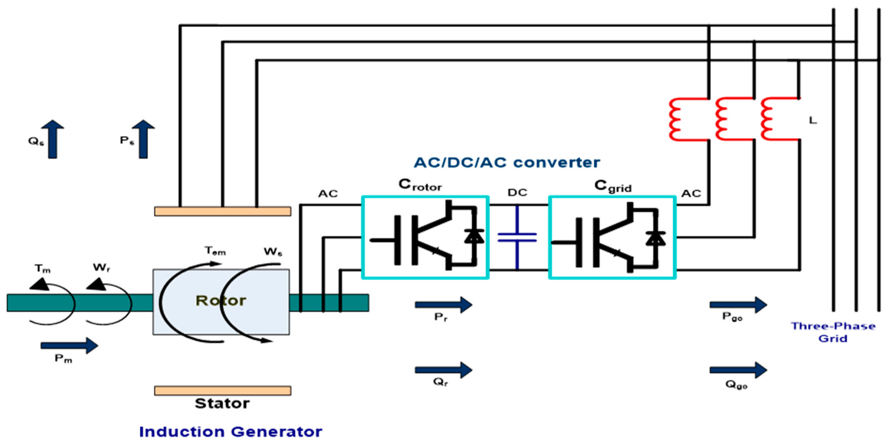
3.3. Operational Features of DFIG Powered by Wind Turbine
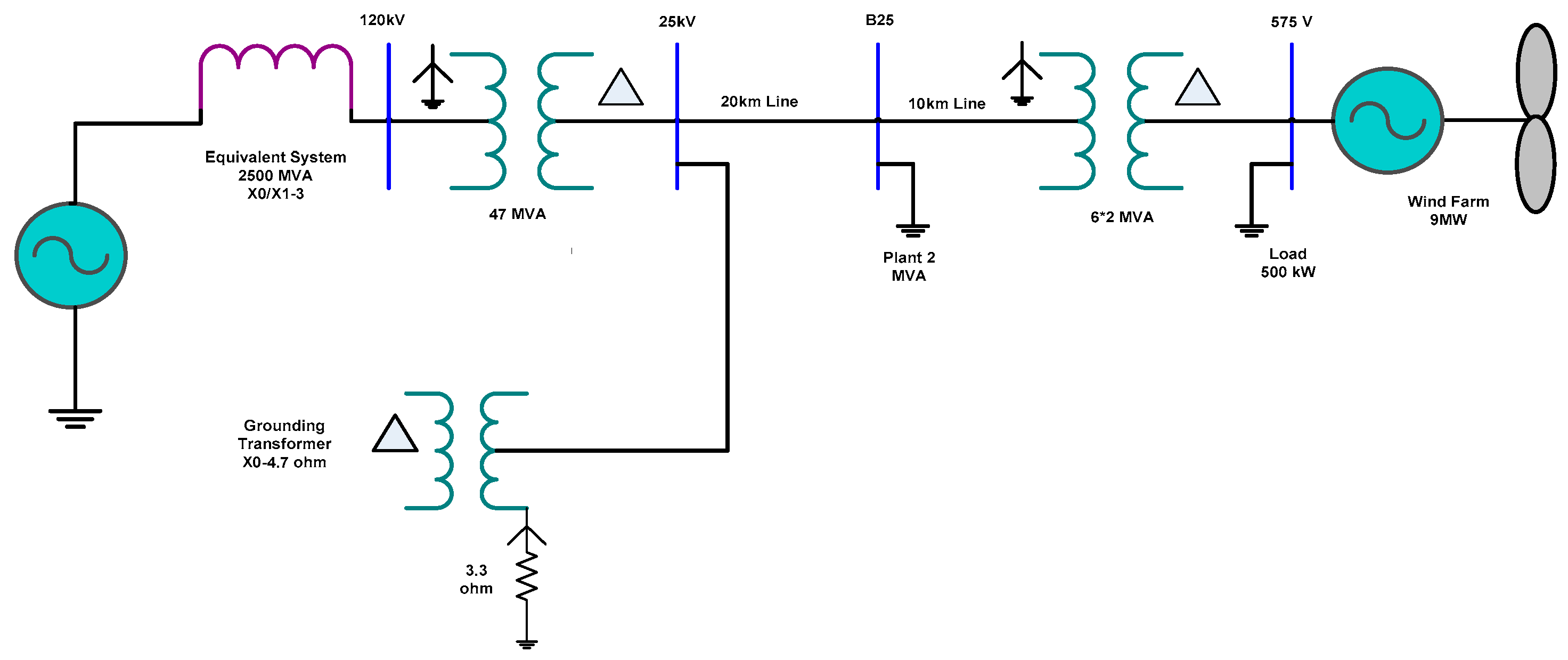
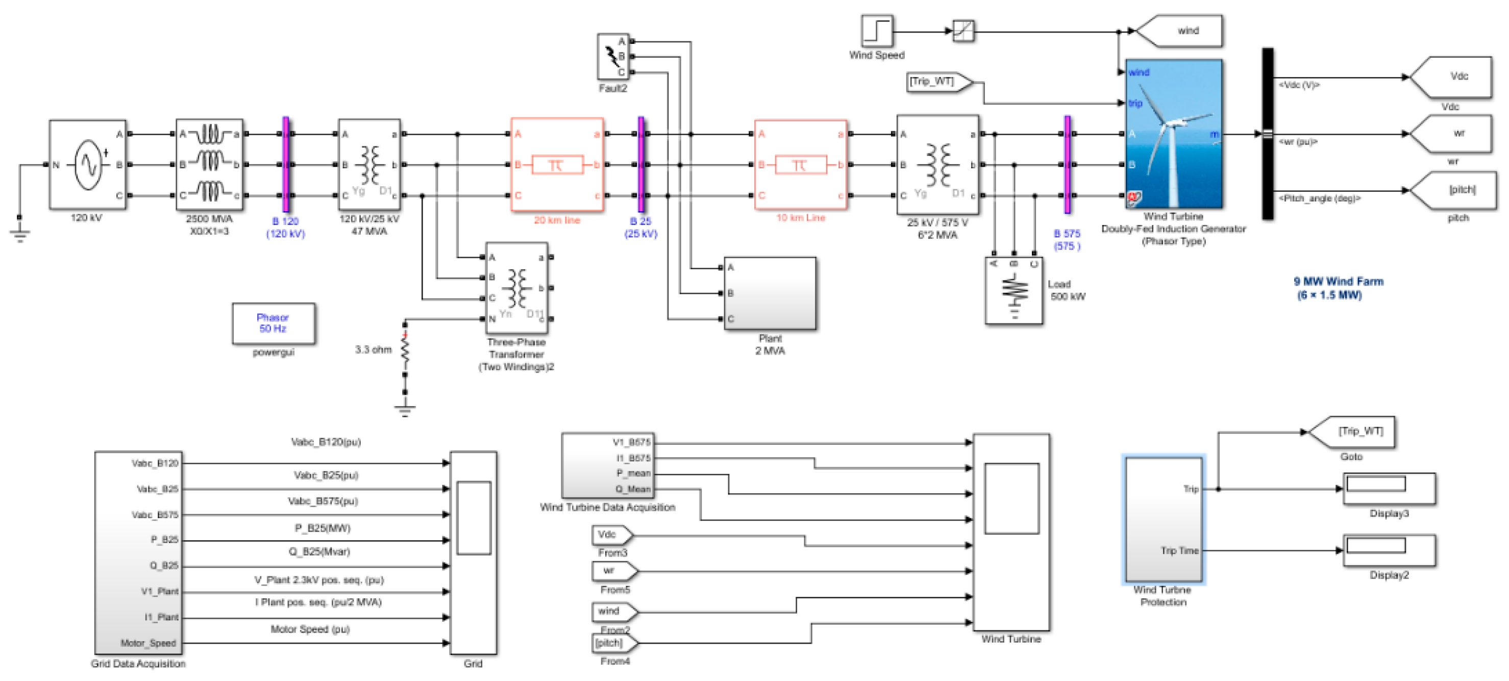
3.4. Single-Line Diagram of a Wind Farm Connected to a Distribution Network
4. Simulation Results
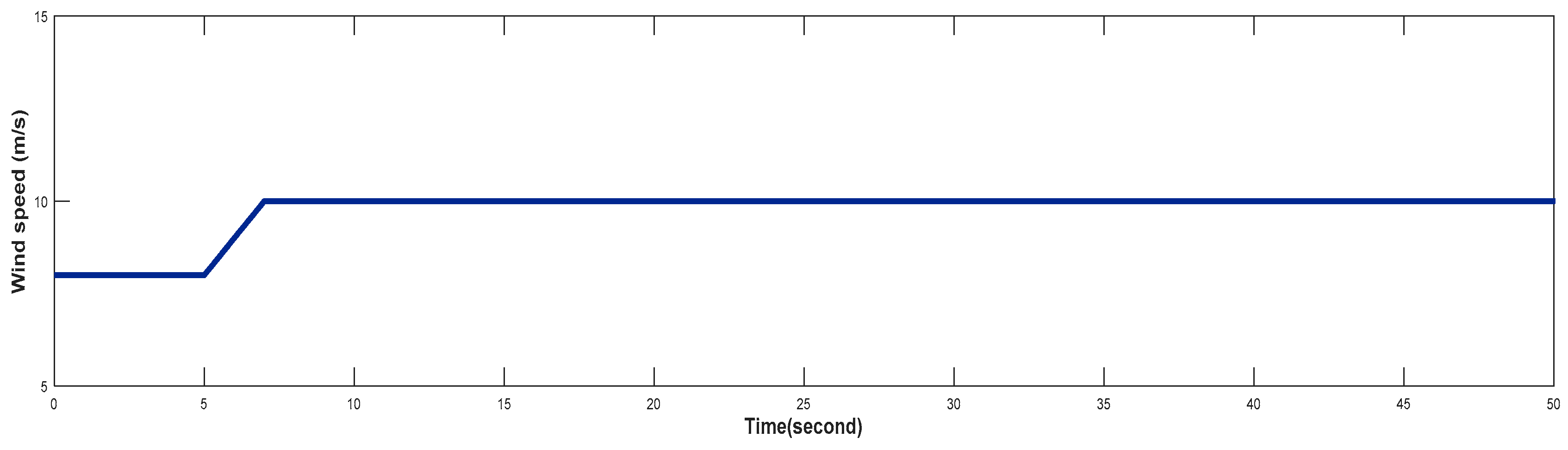
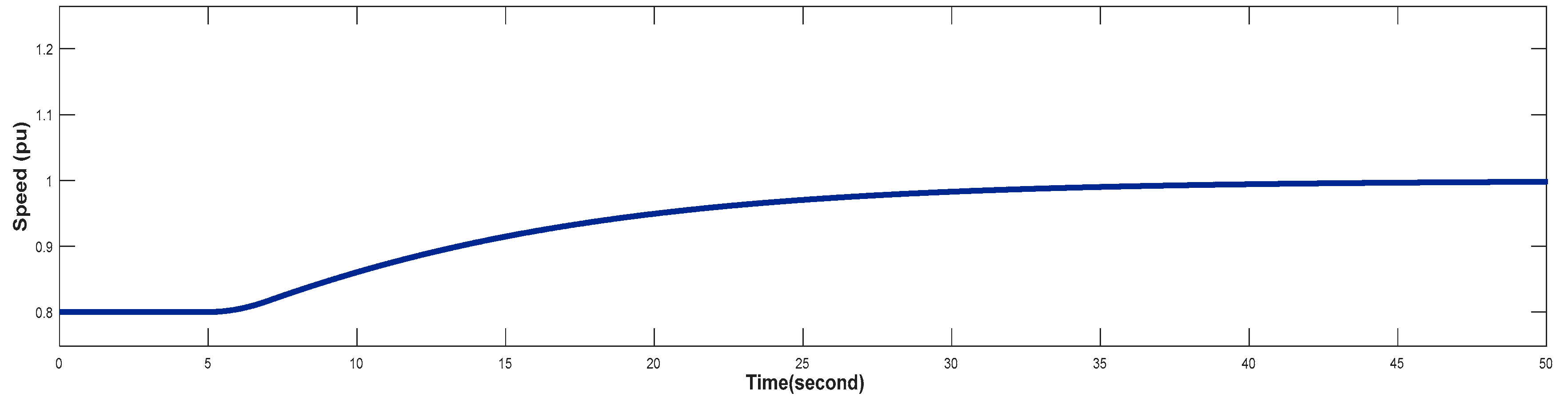
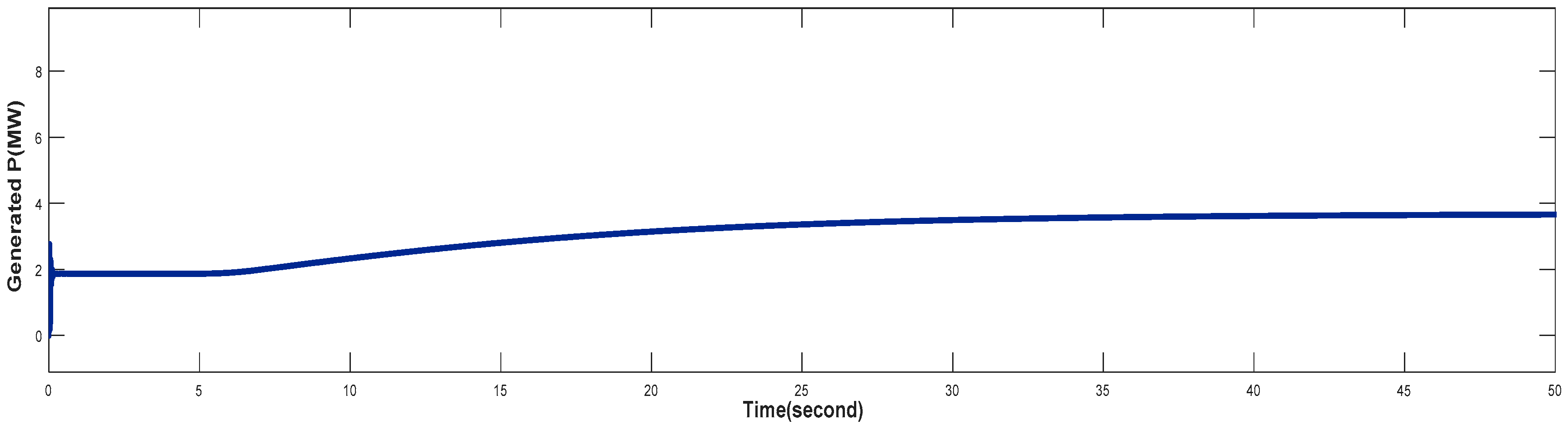
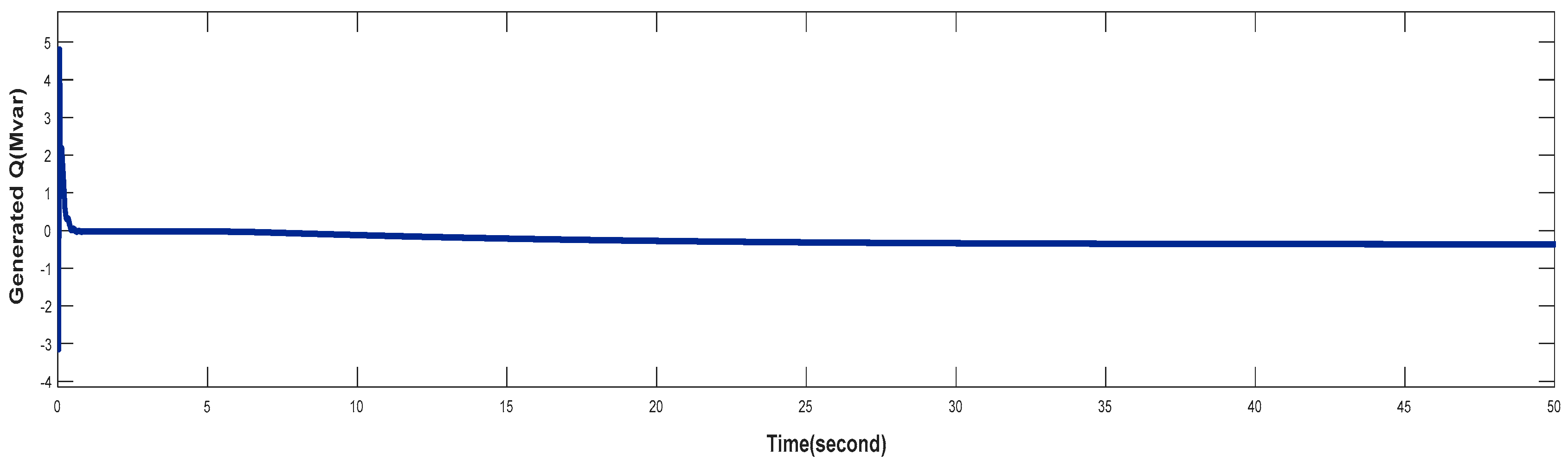
4.1. Turbine Response When Wind Speed Lower Than its Rated Value (Case 1)
4.2. Turbine Response at Rated Value of Wind Speed (Case 2)
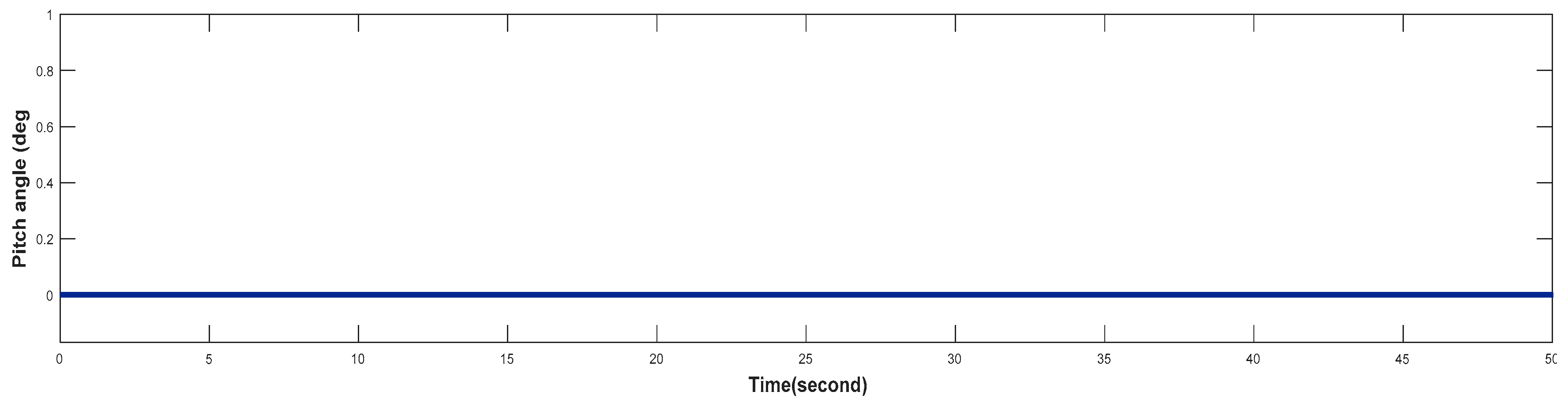
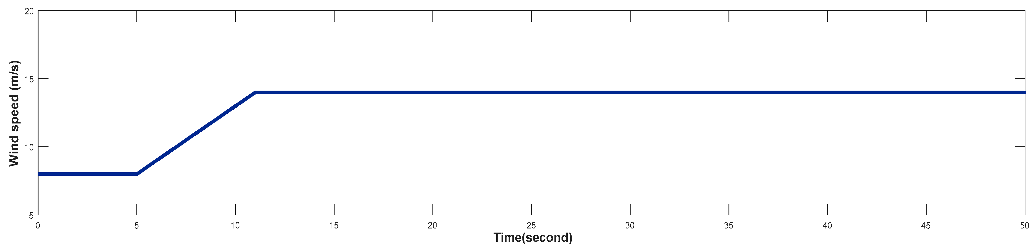
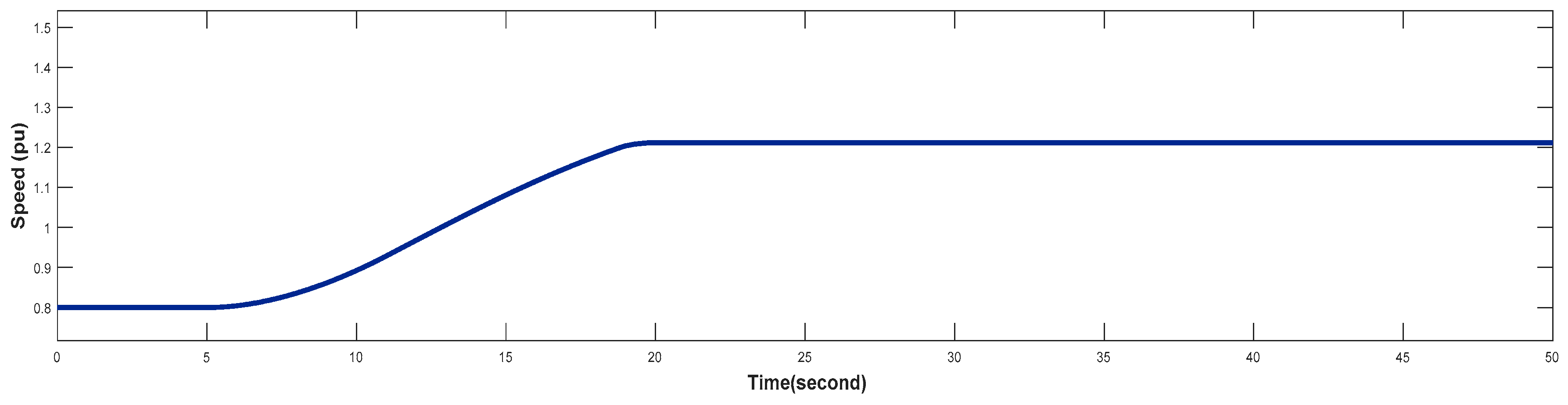
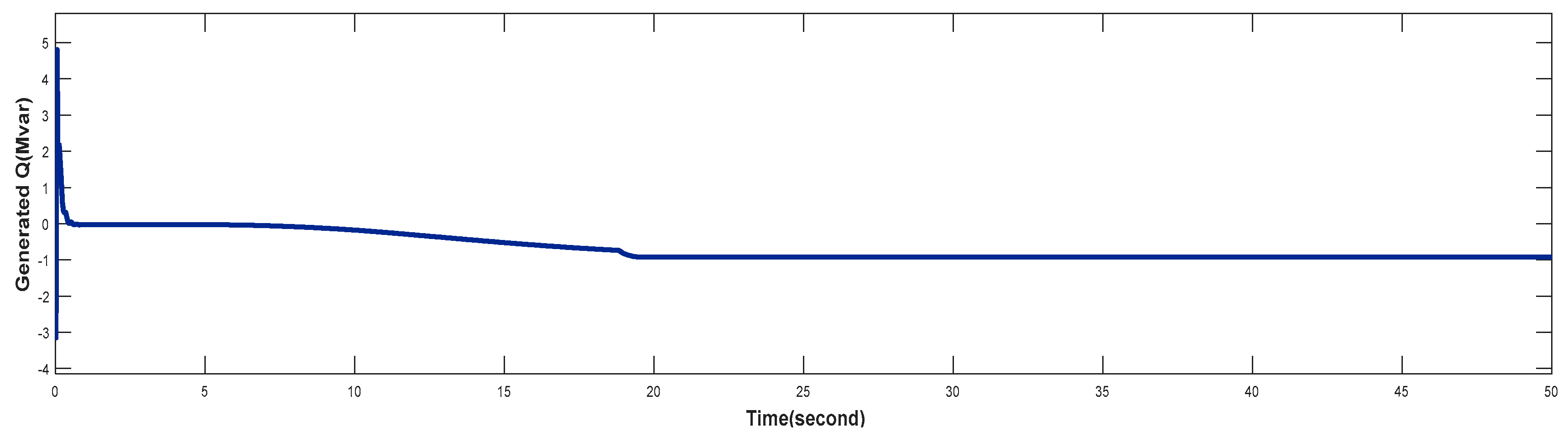
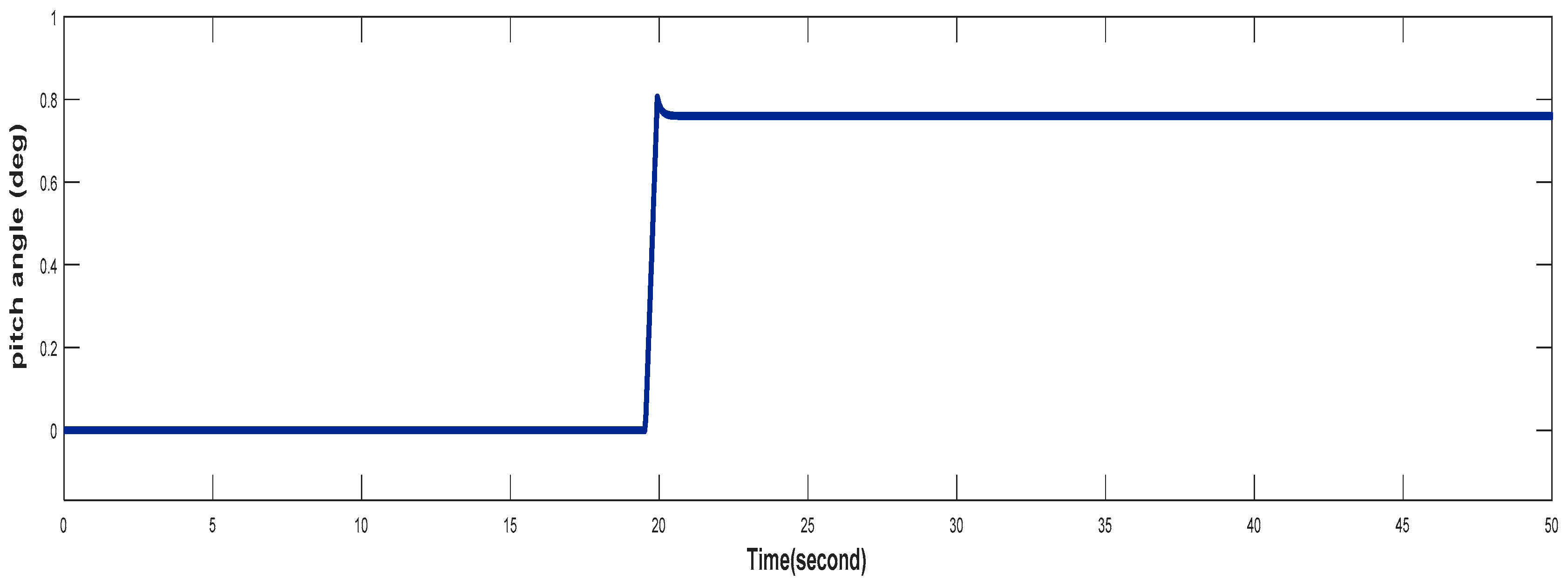
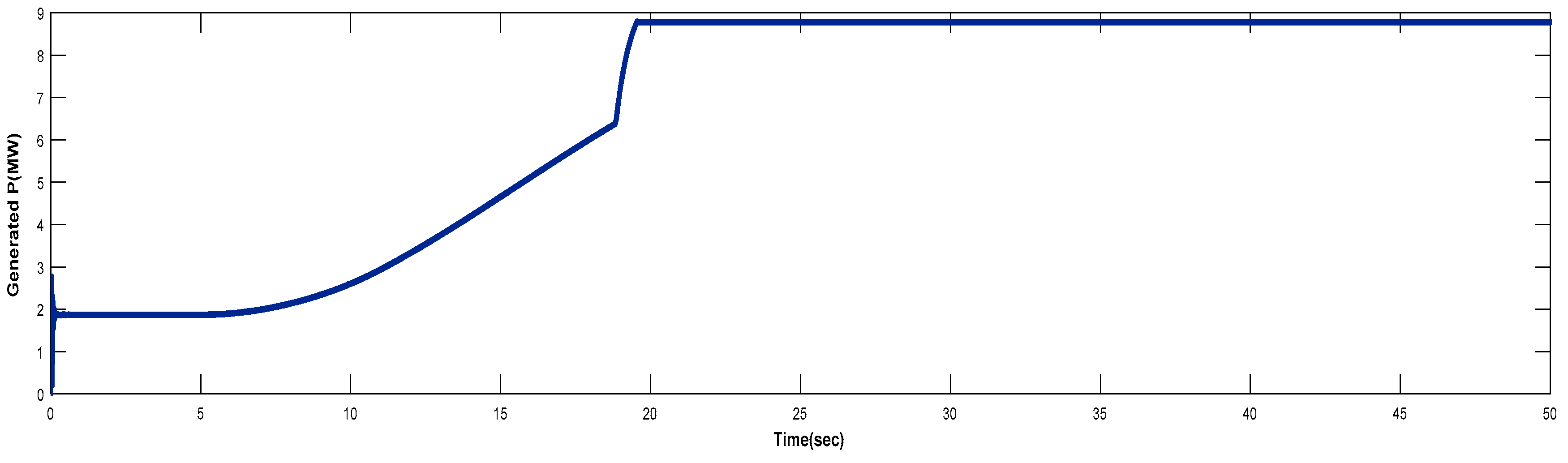
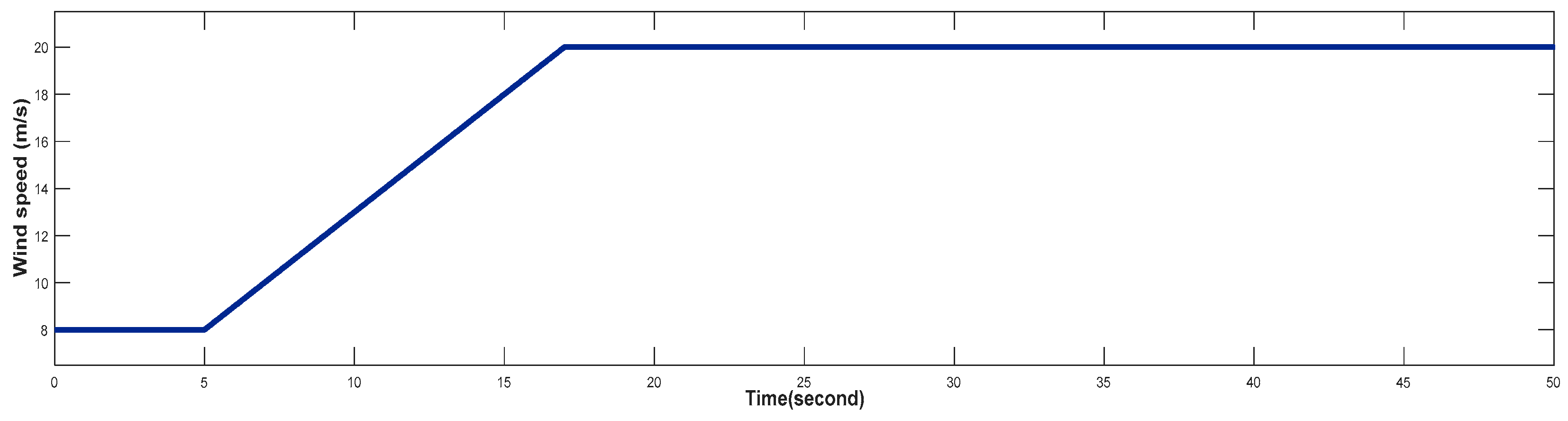
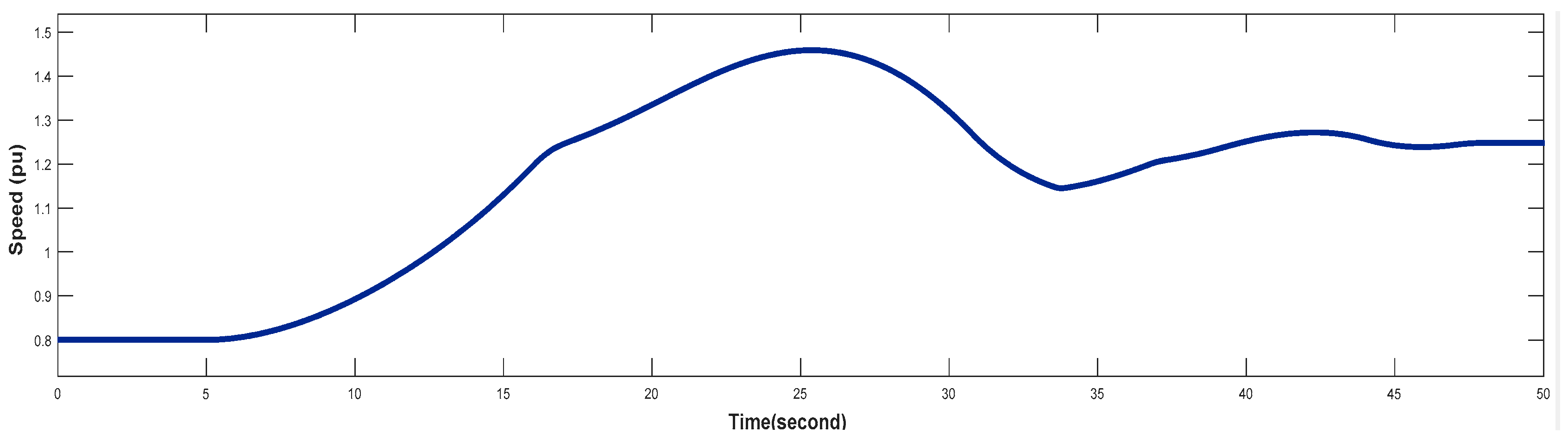
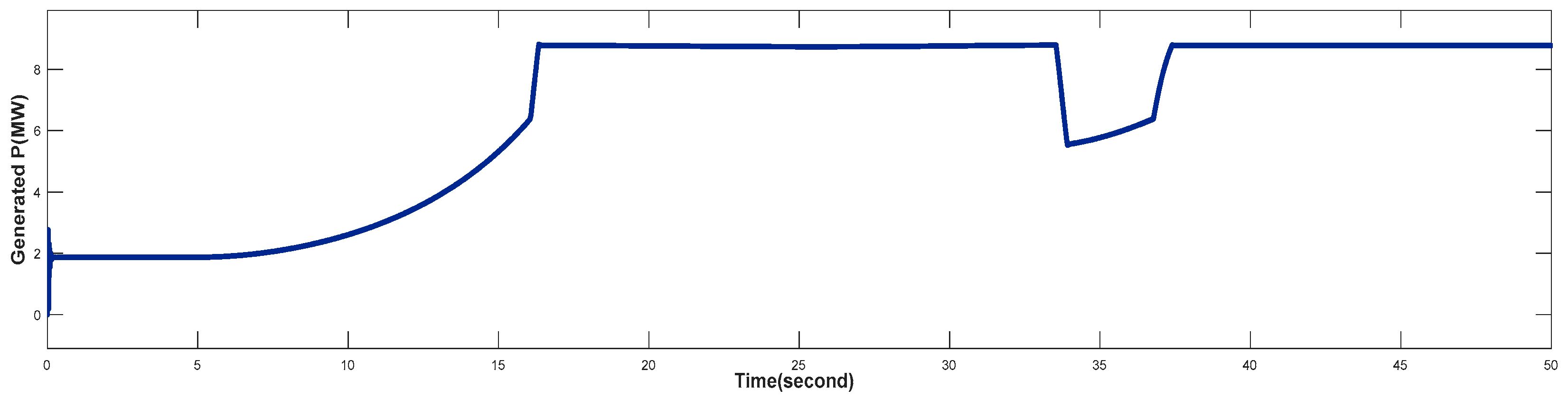
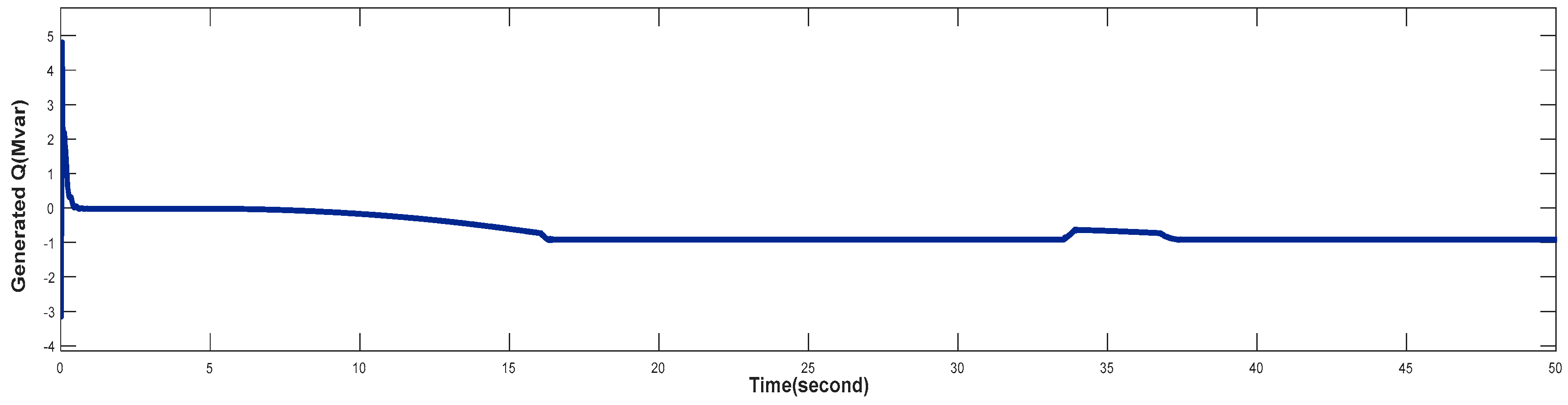
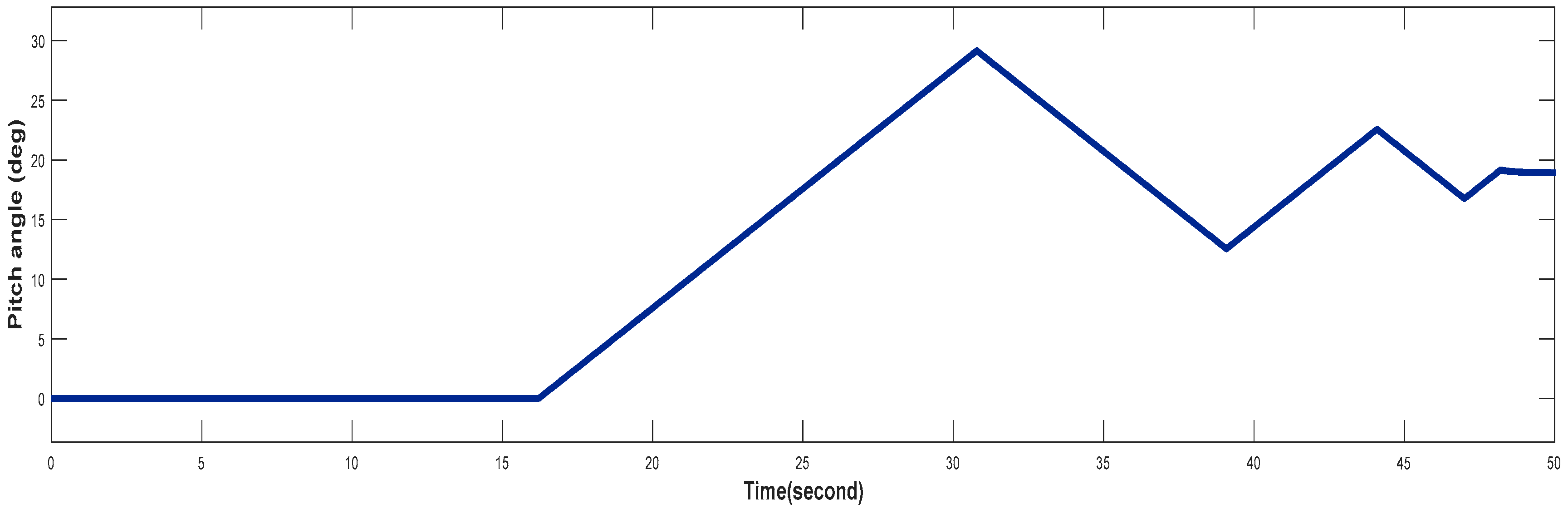
4.3. Turbine Response When Wind Speed Greater Than its Rated Value (Case 3)
5. Conclusion and Future Work
5.1. Conclusion
5.2. Future Work
References
- Chhipa, A.A.; Vyas, S.; Kumar, V.; Joshi, R. MPPT optimisation techniques and power electronics for renewable energy systems: wind and solar energy systems. International Journal of Swarm Intelligence 2022, 7, 141–167. [Google Scholar]
- Qazi, A.; Hussain, F.; Rahim, N.A.; Hardaker, G.; Alghazzawi, D.; Shaban, K.; Haruna, K. Towards sustainable energy: a systematic review of renewable energy sources, technologies, and public opinions. IEEE access 2019, 7, 63837–63851. [Google Scholar]
- Zishan, F.; Mansouri, S.; Abdollahpour, F.; Grisales-Noreña, L.F.; Montoya, O.D. Allocation of Renewable Energy Resources in Distribution Systems while Considering the Uncertainty of Wind and Solar Resources via the Multi-Objective Salp Swarm Algorithm. Energies 2023, 16, 474. [Google Scholar] [CrossRef]
- Sayed, E.T.; Olabi, A.G.; Alami, A.H.; Radwan, A.; Mdallal, A.; Rezk, A.; Abdelkareem, M.A.J.E. Renewable energy and energy storage systems. 2023, 16, 1415.
- Veerendra Kumar, D.J.; Deville, L.; Ritter III, K.A.; Raush, J.R.; Ferdowsi, F.; Gottumukkala, R.; Chambers, T.L. Performance evaluation of 1.1 mw grid-connected solar photovoltaic power plant in louisiana. Energies 2022, 15, 3420. [Google Scholar] [CrossRef]
- Himri, Y.; Rehman, S.; Mostafaeipour, A.; Himri, S.; Mellit, A.; Merzouk, M.; Merzouk, N.K. Overview of the Role of Energy Resources in Algeria’s Energy Transition. Energies 2022, 15, 4731. [Google Scholar] [CrossRef]
- Algarni, S.; Tirth, V.; Alqahtani, T.; Alshehery, S.; Kshirsagar, P. Contribution of renewable energy sources to the environmental impacts and economic benefits for sustainable development. Sustainable Energy Technologies Assessments 2023, 56, 103098. [Google Scholar]
- Prasad, R.M.; Mulla, M.A. Mathematical modeling and position-sensorless algorithm for stator-side field-oriented control of rotor-tied DFIG in rotor flux reference frame. IEEE Transactions on Energy Conversion 2019, 35, 631–639. [Google Scholar]
- Chhipą, A.A.; Chakrabarti, P.; Bolshev, V.; Chakrabarti, T.; Samarin, G.; Vasilyev, A.N.; Ghosh, S.; Kudryavtsev, A. Modeling and control strategy of wind energy conversion system with grid-connected doubly-fed induction generator. Energies 2022, 15, 6694. [Google Scholar] [CrossRef]
- Wilberforce, T.; Ijaodola, O.; Baroutaji, A.; Ogungbemi, E.; Olabi, A.G. Effect of bipolar plate material on proton exchange membrane fuel cell performance. Energies 2022, 15, 1886. [Google Scholar] [CrossRef]
- Olabi, A.G.; Wilberforce, T.; Sayed, E.T.; Elsaid, K.; Abdelkareem, M.A. Prospects of fuel cell combined heat and power systems. Energies 2020, 13, 4104. [Google Scholar] [CrossRef]
- Chhipa, A.A.; Vyas, S.; Kumar, V.; Joshi, R. Role of Power Electronics and Optimization Techniques in Renewable Energy Systems. In Intelligent Algorithms for Analysis and Control of Dynamical Systems, Springer: 2020; pp. 167–175.
- Olabi, A.G.; Wilberforce, T.; Elsaid, K.; Salameh, T.; Sayed, E.T.; Husain, K.S.; Abdelkareem, M.A. Selection Guidelines for Wind Energy Technologies. Energies 2021, 14, 3244. [Google Scholar] [CrossRef]
- Benbouhenni, H.; Bizon, N.; Mosaad, M.I.; Colak, I.; Djilali, A.; Gasmi, H. Enhancement of the power quality of DFIG-based dual-rotor wind turbine systems using fractional order fuzzy controller. Expert Systems with Applications 2023, 121695. [Google Scholar]
- Rao, K.; Rao, K. Wind energy: Technical considerations–contents. in Wind Energy for Power Generation: Meeting the Challenge of Practical Implementation. 2019. Springer.
- Xiahou, K.; Liu, Y.; Wang, L.; Li, M.; Wu, Q. Control of DFIG’s rotor-side converter with decoupling of current loops using observer-based fractional-order sliding-mode regulators. IEEE Access 2019, 7, 163412–163420. [Google Scholar]
- Rajendran, M.; Kumar, L.A. Modeling and Simulation of a DFIG-Based Wind Energy System. in Advances in Smart Grid Technology: Select Proceedings of PECCON 2019—Volume I. 2020. Springer.
- Nian, H.; Xu, Y.; Chen, L.; Zhu, M. Modeling and analysis of DC-link dynamics in DFIG system with an indicator function. IEEE Access 2019, 7, 125401–125412. [Google Scholar]
- SHAHGHOLIAN, G.; ZANJANI, S.M.A. A STUDY OF VOLTAGE SAG IN DISTRIBUTION SYSTEM AND EVALUATION OF THE EFFECT OF WIND FARM EQUIPPED WITH DOUBLY-FED INDUCTION GENERATOR. REVUE ROUMAINE DES SCIENCES TECHNIQUES—SÉRIE ÉLECTROTECHNIQUE ET ÉNERGÉTIQUE 2023, 68, 271–276. [Google Scholar]
- Guediri, A.; Hettiri, M.; Guediri, A. Modeling of a wind power system using the genetic algorithm based on a doubly fed induction generator for the supply of power to the electrical grid. Processes 2023, 11, 952. [Google Scholar] [CrossRef]
- Hore, D.; Sarma, R. Neural network–based improved active and reactive power control of wind-driven double fed induction generator under varying operating conditions. Wind Engineering 2018, 42, 381–396. [Google Scholar]
- Wang, Z.; Liu, Y.; Yang, Z.; Yang, W. Load frequency control of multi-region interconnected power systems with wind power and electric vehicles based on sliding mode control. Energies 2021, 14, 2288. [Google Scholar] [CrossRef]
- Eisa, S.A. Modeling dynamics and control of type-3 DFIG wind turbines: Stability, Q Droop function, control limits and extreme scenarios simulation. Electric Power Systems Research 2019, 166, 29–42. [Google Scholar]
- Zine, H.K.E.; Khoudir, A. Design of a High-Performance Control Scheme for a Grid-Connected DFIG-Based Wind Energy Conversion System Using Model Predictive Control and Hysteresis Model. Elektronika ir Elektrotechnika 2023, 29, 41–49. [Google Scholar]
- Singh, P.; Arora, K.; Rathore, U.C.; Yang, E.; Joshi, G.P.; Son, K.C. Performance Evaluation of Grid-Connected DFIG-Based WECS with Battery Energy Storage System under Wind Alterations Using FOPID Controller for RSC. Mathematics 2023, 11, 2100. [Google Scholar] [CrossRef]
- Alami, H.E.; Bossoufi, B.; Mahfoud, M.E.; Bouderbala, M.; Majout, B.; Skruch, P.; Mobayen, S. Robust Finite Control-Set Model Predictive Control for Power Quality Enhancement of a Wind System Based on the DFIG Generator. Energies 2023, 16, 1422. [Google Scholar] [CrossRef]
- Soomro, M.; Memon, Z.A.; Baloch, M.H.; Mirjat, N.H.; Kumar, L.; Tran, Q.T.; Zizzo, G. Performance improvement of grid-integrated doubly fed induction generator under asymmetrical and symmetrical faults. Energies 2023, 16, 3350. [Google Scholar] [CrossRef]
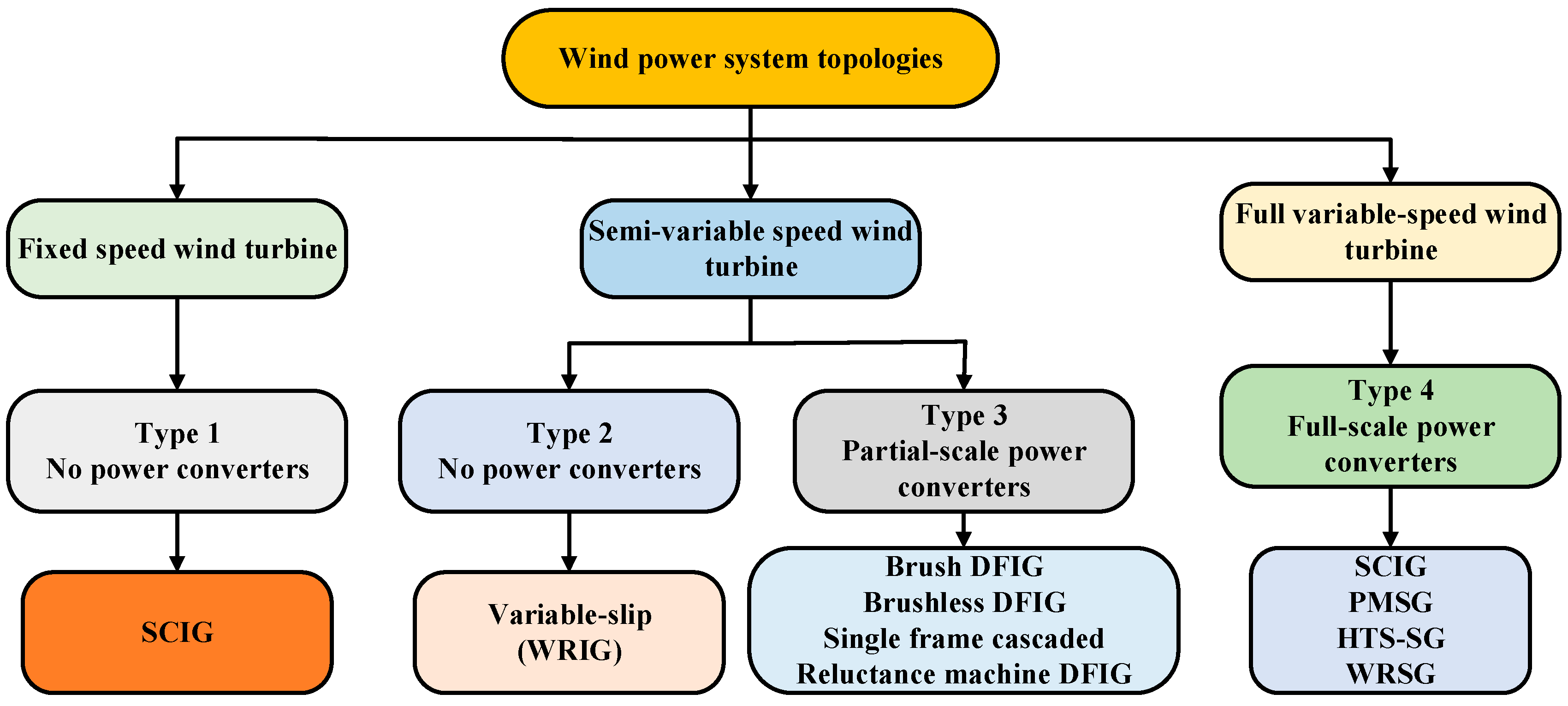

| Types of Wind Turbine Generators (WTGs) | ||||
|---|---|---|---|---|
| Wind turbine technology | Fixed speed | Semi-variable speed | Full-variable speed | |
| Wind generator kinds | SCIG | Variable rotor resistance (WRIG) | DFIG | PMSG |
| Generator types | Kind 1 | Kind 2 | Kind 3 | Kind 4 |
| Power converters | No | Partial | Partial | Full |
| Speed range | Less than 1% rated | Less than 10% rated | ±30% of ratings | complete, 100% rated |
| Soft starter | Yes | Yes | No | No |
| Gearbox | Yes | Yes | Yes | Optimal |
| Control of aerodynamic power | Pitch, Stall, Active stall | Pitch | Pitch | Pitch |
| Reactive power compensator on grid side | Yes | Yes | No | No |
| MPPT and active power control | N/A | Limited | Yes | Yes |
| Short circuit (fault active) | No | No | No/Yes | Yes |
| Efficiency rating | Low | Low/reduced | Good | Good |
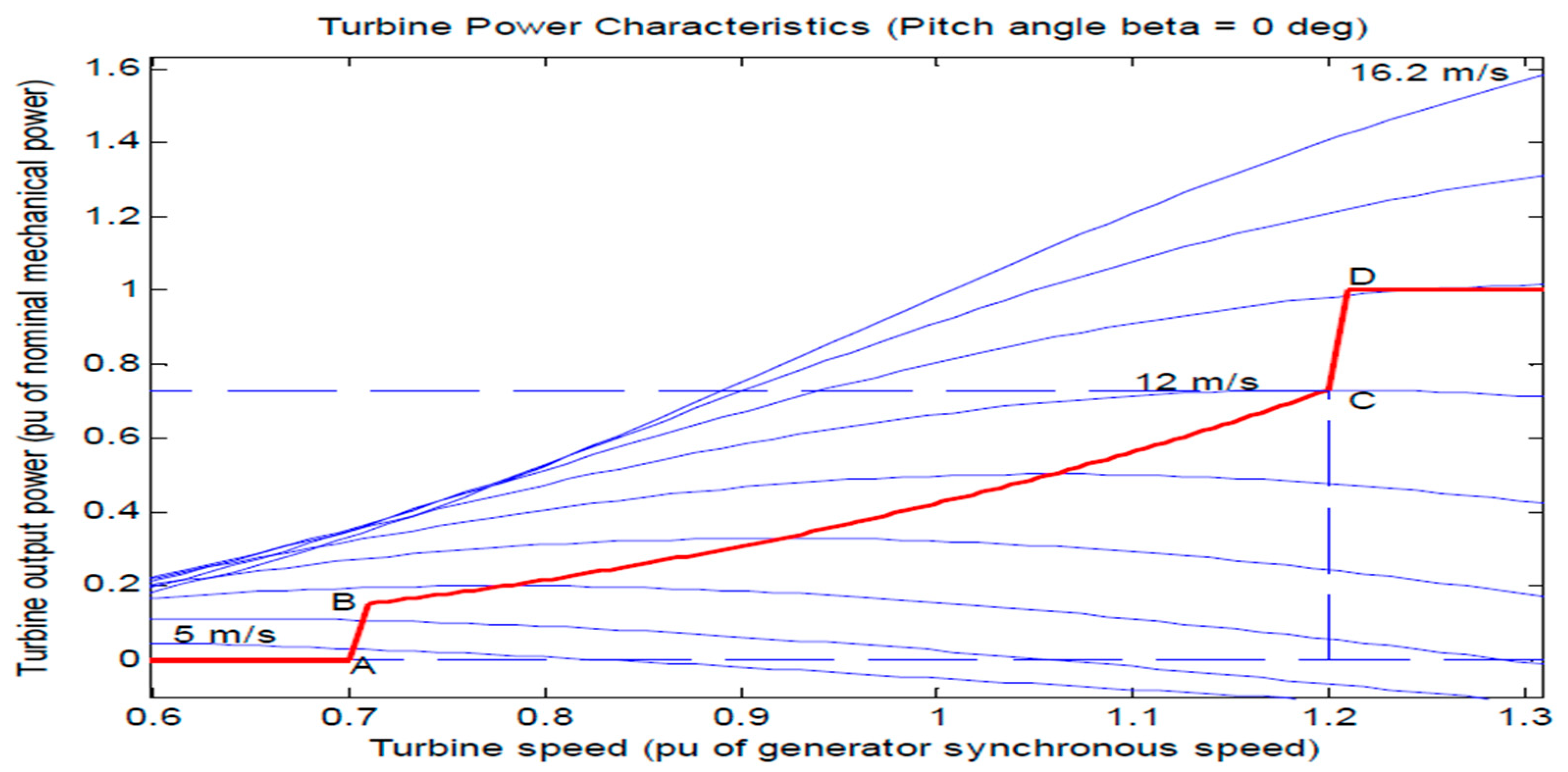
| Spot | Wind Velocity (m/s) | Speed of Turbine | Power Output of a Turbine (pu) |
|---|---|---|---|
| A | 4.23 | 0.7 | 0 |
| B | 7.1 | 0.71 | 0.151 |
| C | 12 | 1.2 | 0.73 |
| Specifications | Specifications Value |
|---|---|
| Air density | 1.225 kg/m3 |
| Pitch angle | 0o |
| Nominal power | 9MW |
| Frequency | 50Hz |
| Rated torque | 12732 N.m |
| Pole pair | 2 |
| Inertia | 127 Kg.m2 |
| Gear ratio | 100 |
| Radius of turbine | 42 |
| Power factor | 0.9 |
| Dc bus capacitor | 6×10⁴ μF |
| Reference voltage | 1 pu |
| Voltage droop | 0.02 pu |
| Gain value | [1 exp(j×2×pi/3) exp(-j×2×pi/3)] |
Disclaimer/Publisher’s Note: The statements, opinions and data contained in all publications are solely those of the individual author(s) and contributor(s) and not of MDPI and/or the editor(s). MDPI and/or the editor(s) disclaim responsibility for any injury to people or property resulting from any ideas, methods, instructions or products referred to in the content. |
© 2025 by the authors. Licensee MDPI, Basel, Switzerland. This article is an open access article distributed under the terms and conditions of the Creative Commons Attribution (CC BY) license (http://creativecommons.org/licenses/by/4.0/).


