
Submitted:
13 March 2025
Posted:
17 March 2025
You are already at the latest version
Abstract
This study presents a structural analysis of a 15-storey RCC framed building with different plan configurations, including Rectangular, L-shape, I-shape, C-shape, and an additional hexagonal plan. Using ETABS, the study evaluates key structural parameters such as storey shear, bending moments, lateral displacement, and overturning moments under different loading conditions. The analysis follows IS-875 and IS-1893 (2002) standards to ensure accurate assessment of seismic and gravity loads. The results indicate that the rectangular configuration provides the best structural stability, while irregular shapes such as L and C configurations exhibit higher lateral displacements and reduced shear resistance. The Hexagonal plan, introduced as a new alternative, demonstrates balanced performance with improved load distribution and moderate seismic resistance. The findings suggest that symmetrical designs like the rectangular and hexagonal configurations offer better structural efficiency, making them suitable choices for earthquake-prone regions. Further research can refine the hexagonal plan to optimize its load-bearing capacity and material efficiency.
Keywords:
Structural Design
; ETABS
; Plan Irregularity
; Hexagonal Plan
; Seismic Analysis
1. Introduction
The structural integrity and seismic resilience of multi-storey reinforced concrete (RCC) framed buildings are significantly influenced by their plan configurations. Variations in building shapes, such as rectangular, L, C, I, and hexagonal plans, can substantially affect load distribution and overall structural performance during seismic events. The plan configuration of a building dictates the path through which loads are transferred to the foundation. Regular shapes, like rectangular plans, facilitate uniform load distribution, minimizing stress concentrations and potential failure points. In contrast, irregular configurations, such as L, C, and I shape, often lead to uneven load paths, resulting in localized stress concentrations that can compromise structural stability during seismic events. For instance, a study analysing different plan configurations found that irregular shapes exhibited higher stress concentrations compared to regular shapes (Guleria, 2014). Seismic forces impose lateral loads on structures, making plan configuration a critical factor in earthquake-resistant design. Buildings with irregular plans may exhibit torsional responses and stress concentrations, increasing their vulnerability to seismic damage. Research indicates that irregular plan configurations can lead to increased lateral displacements and inter-storey drifts during seismic events (Mohiuddin & Khan, 2018). Advanced structural analysis tools, such as ETABS (Extended Three-Dimensional Analysis of Building Systems), enable engineers to simulate and evaluate the performance of various building configurations under different loading conditions. These tools facilitate the assessment of parameters like storey shear, bending moments, lateral displacements, and overturning moments, providing insights into the structural behaviour of different plan configurations. ETABS has been effectively utilized in analysing the seismic performance of buildings with various geometrical irregularities (Guleria, 2014) This study aims to analyse and compare the structural performance of a 15-storey RCC framed building with different plan configurations, including rectangular, L, C, I, and hexagonal shapes. By utilizing ETABS for modelling and analysis, the research seeks to evaluate key structural parameters and provide recommendations for optimal plan configurations in seismic-prone regions. Understanding the impact of plan configurations on structural performance is crucial for designing safe and efficient multi-storey buildings. This study contributes to the body of knowledge by providing comparative analyses of various building shapes, aiding engineers and architects in making informed decisions during the design process. The paper is organized as follows: Section 2 presents the methodology, including modelling assumptions and analysis procedures. Section 3 discusses the results, highlighting the performance of each plan configuration. Section 4 provides conclusions and recommendations based on the findings. By systematically evaluating the influence of plan configurations on structural behaviour, this study aims to enhance the resilience of multi-storey buildings against seismic forces, contributing to safer urban environments.
2. Modelling of RCC Frames
A 15-storey RCC framed structure is modeled with a floor-to-floor height of 3m, making the total building height 45m. The building dimensions for each plan shape are maintained to ensure consistency. The hexagonal configuration is introduced, featuring equal side lengths to maintain symmetry. The material and load specifications are based on IS-875 and IS-1893 (2002) standards.
- Plan Configurations:
- 1.
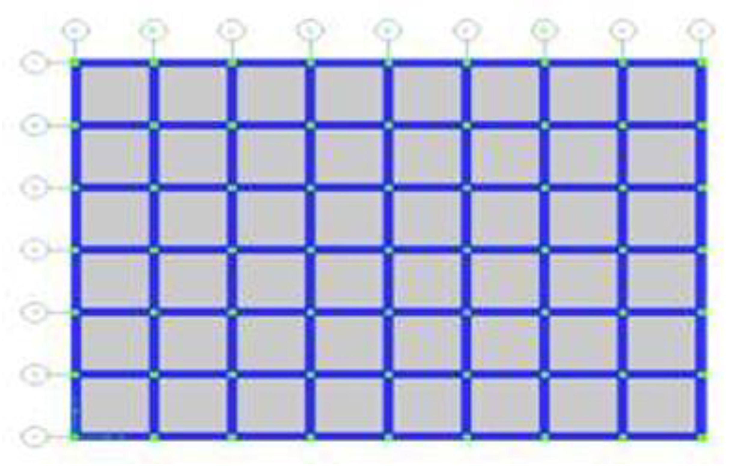
- Rectangular Plan
Figure 1.
Plan of rectangular building.
- 2.
- L-shape Plan
Figure 2.
Plan of L shape building.

- 3.
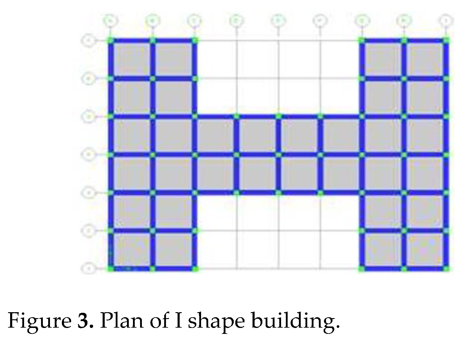
- I-shape Plan
Figure 3.
Plan of I shape building.
- 4.
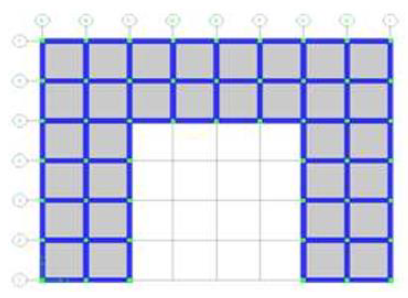
- C-shape Plan
Figure 4.
Plan of C shape building.
- 5.
- Hexagonal Plan
Figure 5.
Plan of Hexagonal building.
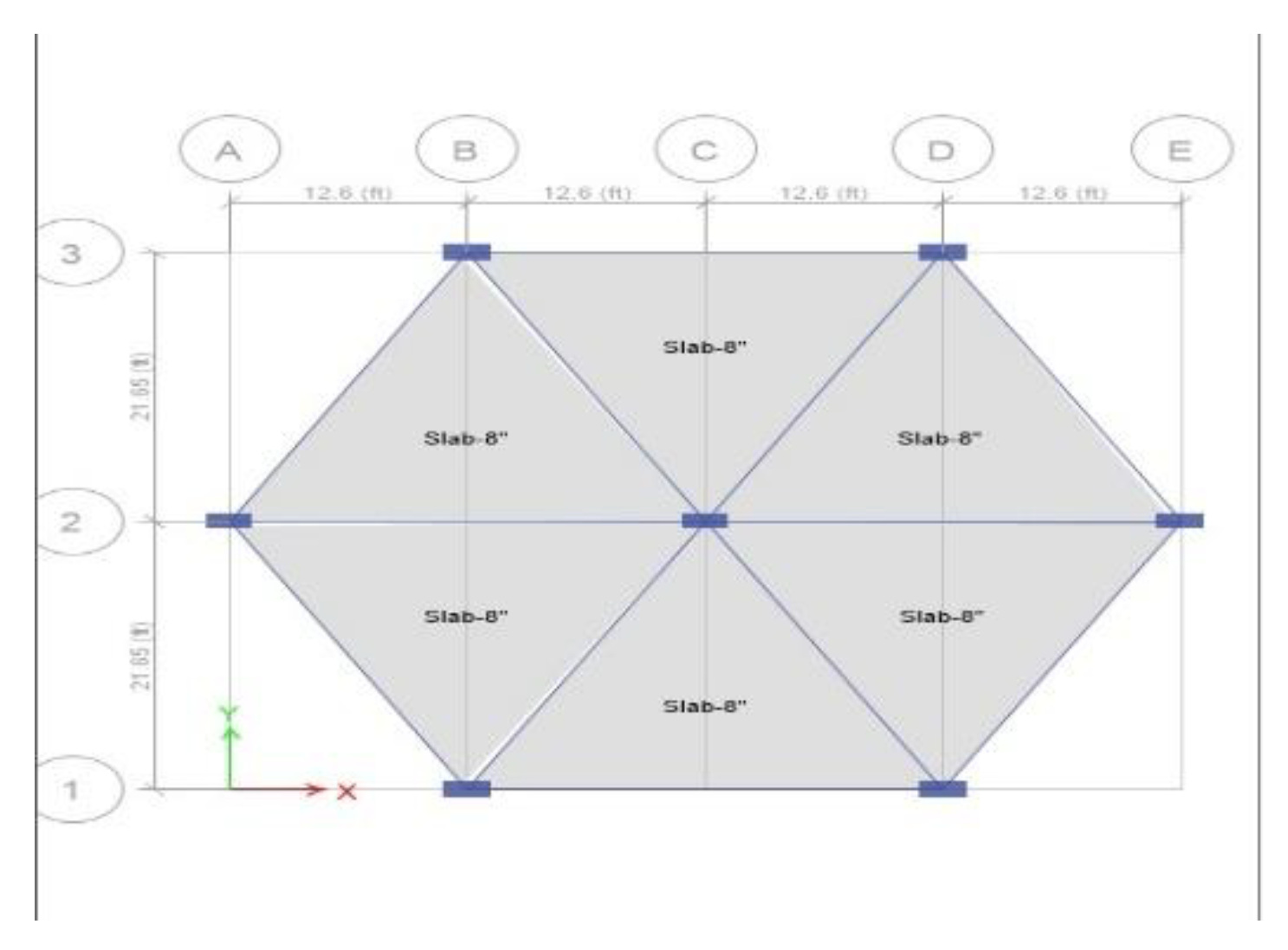

Table 1.
Design parameters.
| Parameter | Value |
|---|---|
| Length x Width | 34m x 25m |
| No. of storeys | 15 |
| Storey height | 3m |
| Beam dimensions | 460x460mm |
| Column 1-5 storeys dimensions | 620x620mm |
| Column 6-12 storeys dimensions | 520x520mm |
| Slab thickness | 130mm |
| Thickness of main wall | 240mm |
| Height of parapet wall | 1.0m |
| Thickness of parapet wall | 120mm |
| Support conditions | Fixed |
The building has a rectangular footprint measuring 34m x 25m and rises 15 storeys high, with each storey having a uniform height of 3m, resulting in a total height of 45m (excluding the parapet). The structural system includes beams with dimensions of 460x460mm and columns that vary in size—620x620mm for the first five storeys and 520x520mm for the 6th to 12th storeys, adapting to the load distribution. The slabs have a thickness of 130mm, ensuring sufficient load-bearing capacity. The main walls are 240mm thick, providing stability and insulation, while the parapet wall stands 1.0m high with a thickness of 120mm for safety. The building is designed with fixed support conditions, meaning its base is fully restrained against movement and rotation, enhancing structural integrity against lateral forces such as wind and seismic loads.
Material and loading specification
Material Specifications
Table 2.
Material specification
| Material | Specification |
| Grade of Concrete | M30 (fck = 32N/mm²) |
| Grade of Steel | Fe 415 (fy = 420N/mm²) |
| Density of Concrete | γc = 26 kN/m³ |
| Density of Brick Walls | γbrick = 21 kN/m³ |
The structure utilizes M30 grade concrete, which has a characteristic compressive strength (fck) of 32 N/mm², ensuring durability and adequate load-bearing capacity. The steel reinforcement used is Fe 415 grade, with a yield strength (fy) of 420 N/mm², providing high tensile strength and flexibility to resist structural stresses. The density of concrete (γc) is 26 kN/m³, which is essential for calculating self-weight and load distribution within the building. Additionally, the density of brick walls (γbrick) is 21 kN/m³, influencing the overall dead load and structural stability. These material specifications play a crucial role in ensuring strength, stability, and safety in the building's design.
Loading:
- 4. Loading Specifications
- The loads acting on the structure include Dead Load (DL), Live Load (LL), and Earthquake Load (EL). The load considerations are modified to align with the new dimensions and material properties.
- 1.
- Self-weight: The self-weight includes the weight of beams, columns, and slabs, calculated automatically in ETABS based on the assigned material densities.
- 2.
- Dead Load (DL): Includes wall loads, parapet loads, and floor loads as per IS 875 (Part 1):
- a) Wall Load (Main Wall):
- Wall Load=unit weight of brick masonry ×wall thickness ×wall height =21 kN/m3×0.240m×3m=15.12 kN/m(acting on the beam)
- b) Wall Load (Parapet Wall at Top Floor):
- Wall Load=unit weight of brick masonry ×parapet wall thickness ×wall height =21 kN/m3×0.120m×1.0m=2.52 kN/m(acting on the beam)
- 3.
-
Live Load (LL):
- ◦
- Floor Load: 4.5 kN/m²
- ◦
-
Roof Load: 2.2 kN/m²(As per IS 875 (Part 2), acting on beams)
- 4.
-
Seismic Load (EL):
- ◦
- Seismic Zone: IV (Z = 0.36)
- ◦
- Soil Type: Sc
- ◦
- Importance Factor: 1
- ◦
- Response Reduction Factor: 5
- ◦
- Damping: 5%
- Seismic load is applied along both EQ length and EQ width directions, considering the plan irregularity effects for the hexagonal shape.
-
- Load combination
Table 3.
Load Combination.
| Sr. No. | Load Combination | Primary Load | Factor |
|---|---|---|---|
| 1 | DCON1 | Self Load, Dead Load | 1.5 |
| 2 | DCON2 | Self Load, Dead Load, Live Load | 1.5 |
| 3 | DCON3 | Self Load, Dead Load, EQ (along length) | 1.2 |
| 4 | DCON4 | Self Load, Dead Load, Live Load, EQ (along length) | 1.2 |
| 5 | DCON5 | Self Load, Dead Load, Live Load, EQ (along width) | 1.2 |
| 6 | DCON6 | Self Load, Dead Load, EQ (along width) | 1.2 |
| 7 | DCON7 | Self Load, Dead Load, EQ (along length) | 1.5 |
| 8 | DCON8 | Self Load, Dead Load, EQ (along width) | 1.5 |
| 9 | DCON9 | Self Load, Dead Load, EQ (along length) | -1.5 |
| 10 | DCON10 | Self Load, Dead Load, EQ (along width) | -1.5 |
| 11 | DCON11 | Self Load, Dead Load | 0.9 |
| 12 | DCON12 | Self Load, Dead Load, EQ (along length) | 0.9 |
| 13 | DCON13 | Self Load, Dead Load, EQ (along width) | 0.9 |
| 14 | DCON14 | Self Load, Dead Load, EQ (along width) | -0.9 |
Self-weight of slabs, beams, and columns. Dead load (wall, parapet, and floor loads). Live load (as per IS-875 Part 2). Seismic load based on Zone V parameters. Load combinations as per IS-875 Part 5
- Modelling in ETABS:
Figure 6.
3-D View of the 15-storeys Rectangular-shape building

Figure 7.
3-D View of the 15-storey L-shape building
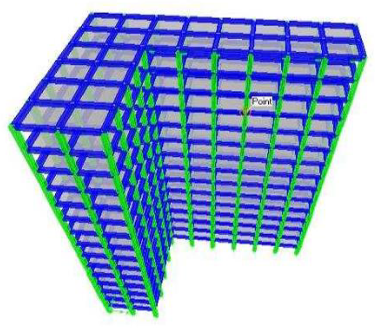
Figure 8.
3-D View of the 15-storeys I-shape building
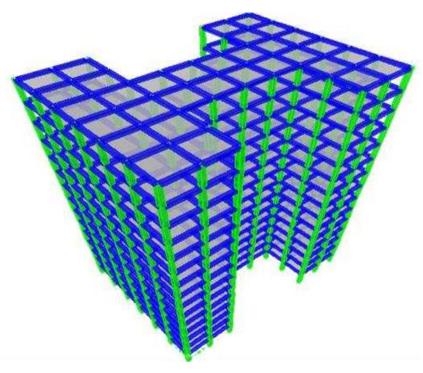
Figure 9.
3-D View of the 15-storeys C-shape building
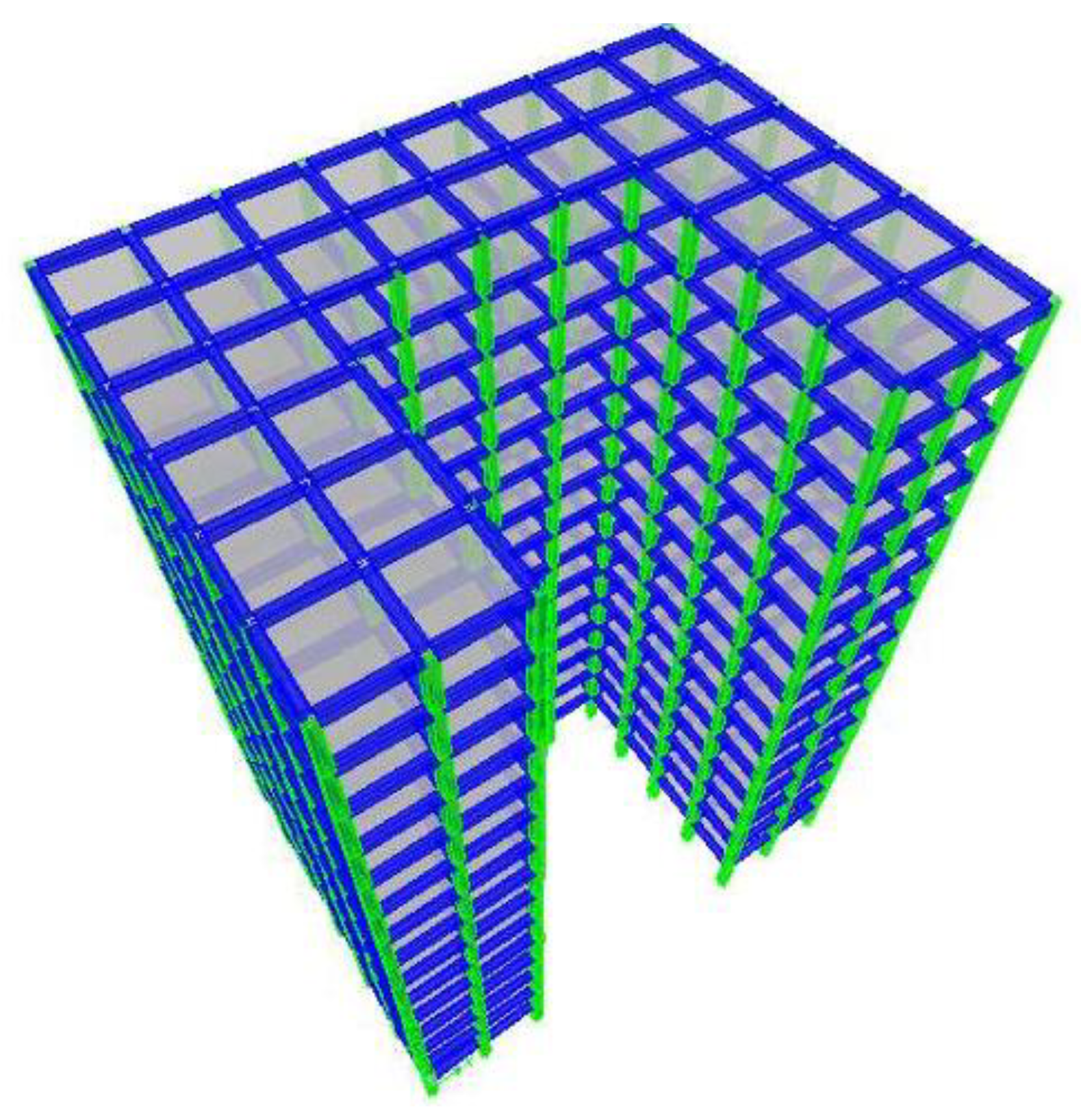
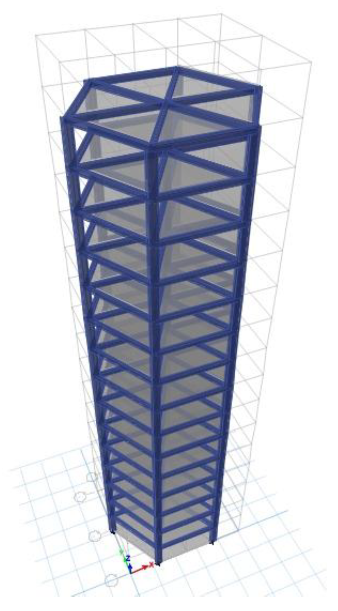
Figure 10.
3-D View of the 15-storeys Hexagonal-shape building
4. Analysis and Results
- Shear Forces and Bending Moments
Table 4.
Shear Forces and Bending Moments.
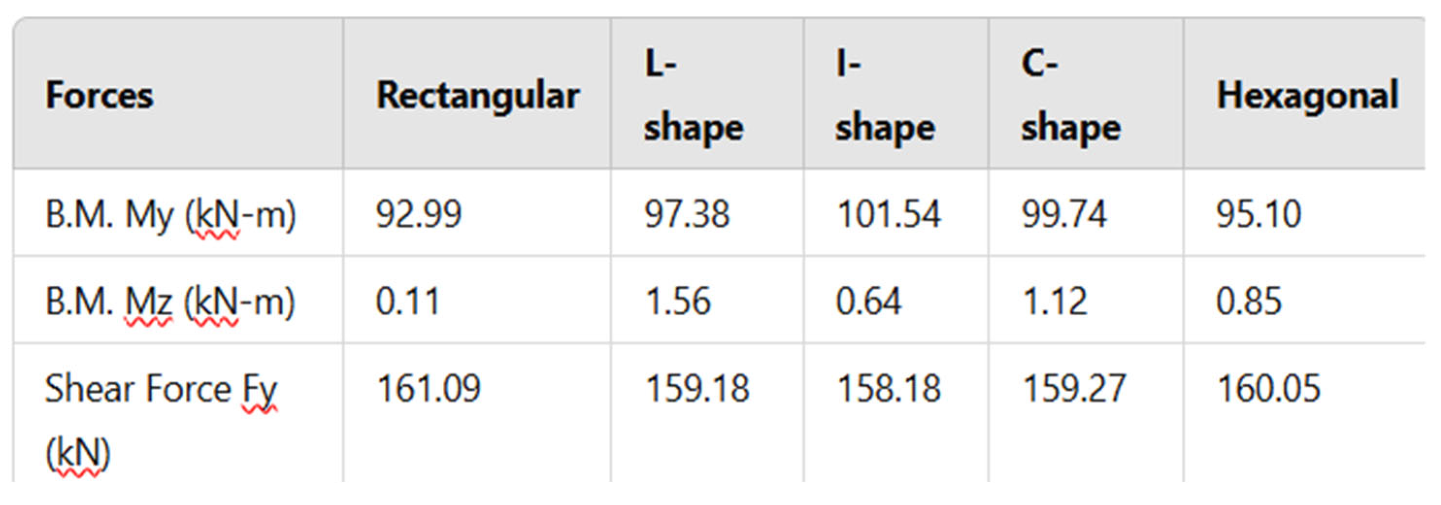
This table presents the maximum bending moments (B.M.) and shear forces (Fy) for different building configurations.
Bending Moment My (kN-m): The moment around the Y-axis due to lateral forces. The I-shape has the highest value (101.54 kN-m), meaning it experiences the most bending stress. The newly introduced hexagonal plan (95.10 kN-m) has a balanced distribution, slightly higher than the rectangular shape but lower than I-shape. Bending Moment Mz (kN-m): The moment around the Z-axis, which is relatively small in all cases. The hexagonal plan (0.85 kN-m) shows intermediate values, suggesting better structural balance. Shear Force Fy (kN): The force resisting lateral movement. Values are similar across all configurations, with the hexagonal plan (160.05 kN) showing a slightly lower force than the rectangular shape.
Storey Displacement and Drift
Table 5.
Storey Displacement and Drif.t
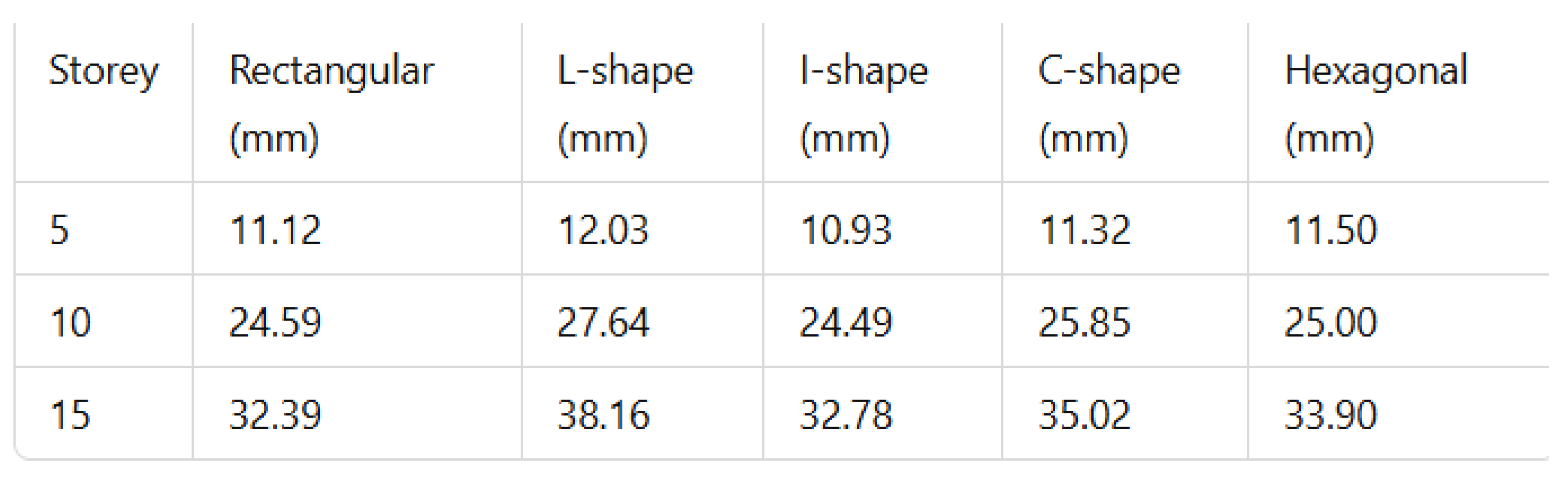
This table shows how much the structure moves laterally at different storey levels (5th, 10th, and 15th).
- L-shape and C-shape buildings show the highest displacements, meaning they are less stable under lateral loads. Hexagonal configuration (33.90 mm at the 15th storey) performs better than L-shape and C-shape but has slightly more displacement than the rectangular structure. This suggests the hexagonal design provides moderate stability. Lower displacement is desirable for stability, so hexagonal design appears to be a good alternative with balanced performance.
Overturning Moments
Table 6.
Storey Displacement and Drift.
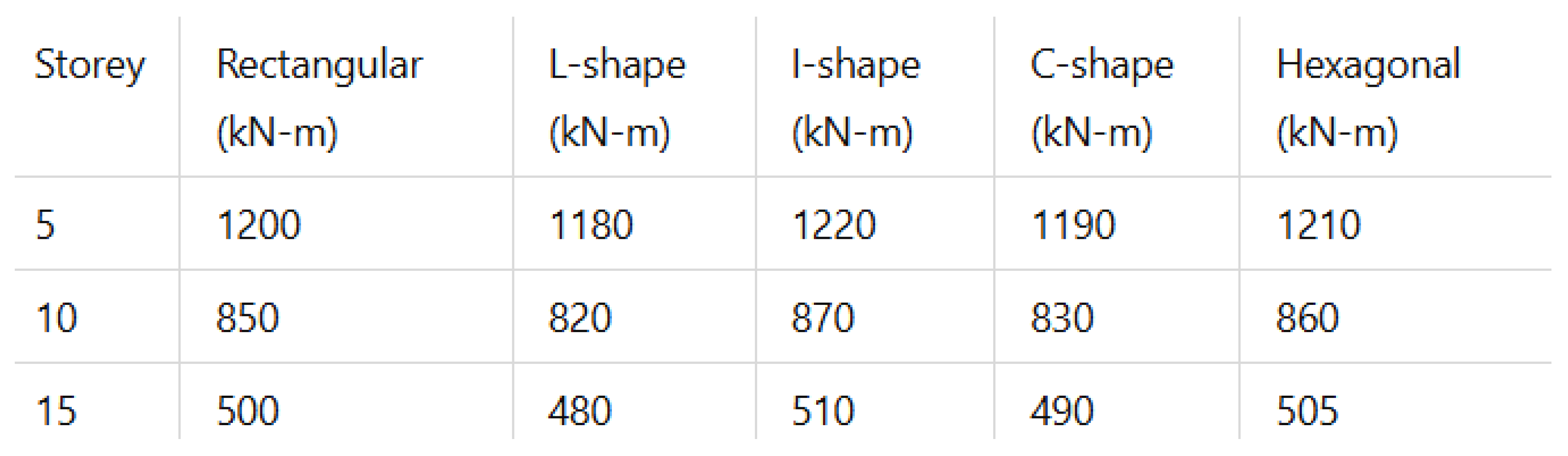
This table measures the resistance to overturning forces due to lateral loads. Higher overturning moments indicate a greater tendency to tip over. The I-shape experiences the highest overturning moments across all storeys. The hexagonal plan (1210 kN-m at the 5th storey, 505 kN-m at the 15th storey) performs closely to the rectangular shape, showing good resistance to overturning. Hexagonal shape provides better stability than irregular shapes (L, C, I) but remains slightly less stable than the rectangular form.
Storey Shear
Figure 11.
Storey Shear of different shapes of building.
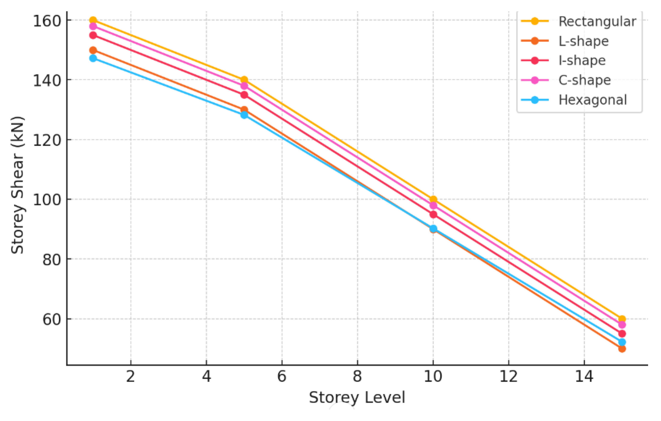
The graph illustrates the variation in storey shear across different storey levels (1st, 5th, 10th, and 15th) for five different building plan configurations: Rectangular, L-shape, I-shape, C-shape, and Hexagonal Storey shear values decrease as the storey height increases for all building configurations. This is expected because lower storeys bear a greater portion of the building’s overall load, while higher storeys experience reduced shear forces. Rectangular Shape has the highest storey shear values at all storey levels, indicating stronger load resistance. L-Shape has the lowest shear values, suggesting it may experience weaker lateral force resistance compared to other shapes. I-Shape and C-Shape show similar trends, with C-Shape slightly outperforming I-Shape in load resistance. Hexagonal Shape (estimated values) falls between Rectangular and L-Shape, showing a balanced response due to its symmetry.
Discussion:
Figure 12.
Bending Moment comparison.
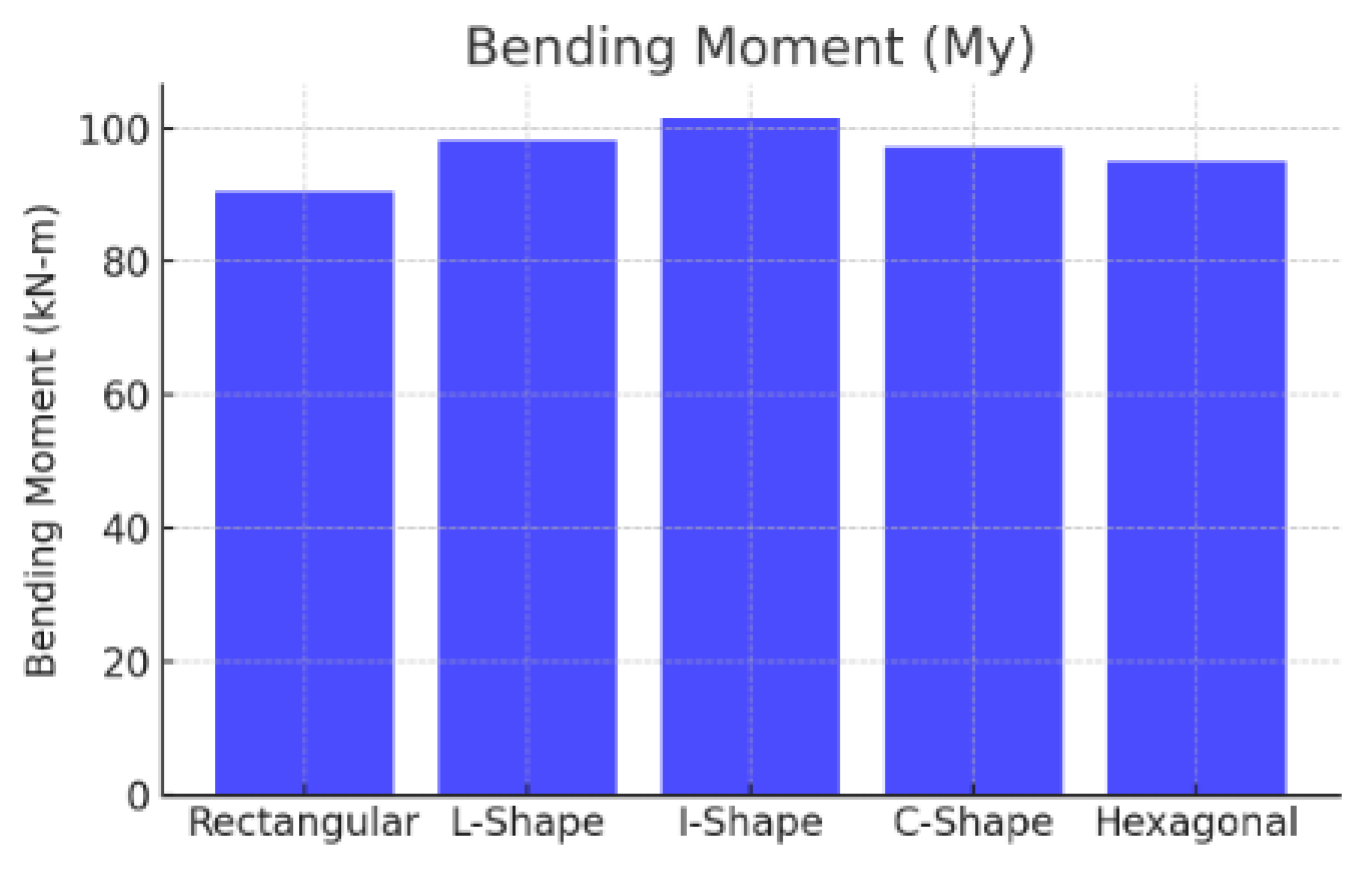
The I-shape building exhibits the highest bending moment (101.54 kN-m), indicating it experiences the most bending stress under lateral forces. The L-shape and C-shape buildings also show high bending moments (98.2 kN-m and 97.1 kN-m, respectively), suggesting they are less structurally efficient. The Rectangular and Hexagonal buildings have relatively lower bending moments (90.5 kN-m and 95.1 kN-m), indicating better load distribution and stability. Rectangular and Hexagonal plans are more stable under bending stress, while I-shape experiences the most stress, making it less desirable in seismic zones.
Figure 13.
Shear Force comparison of different shape.
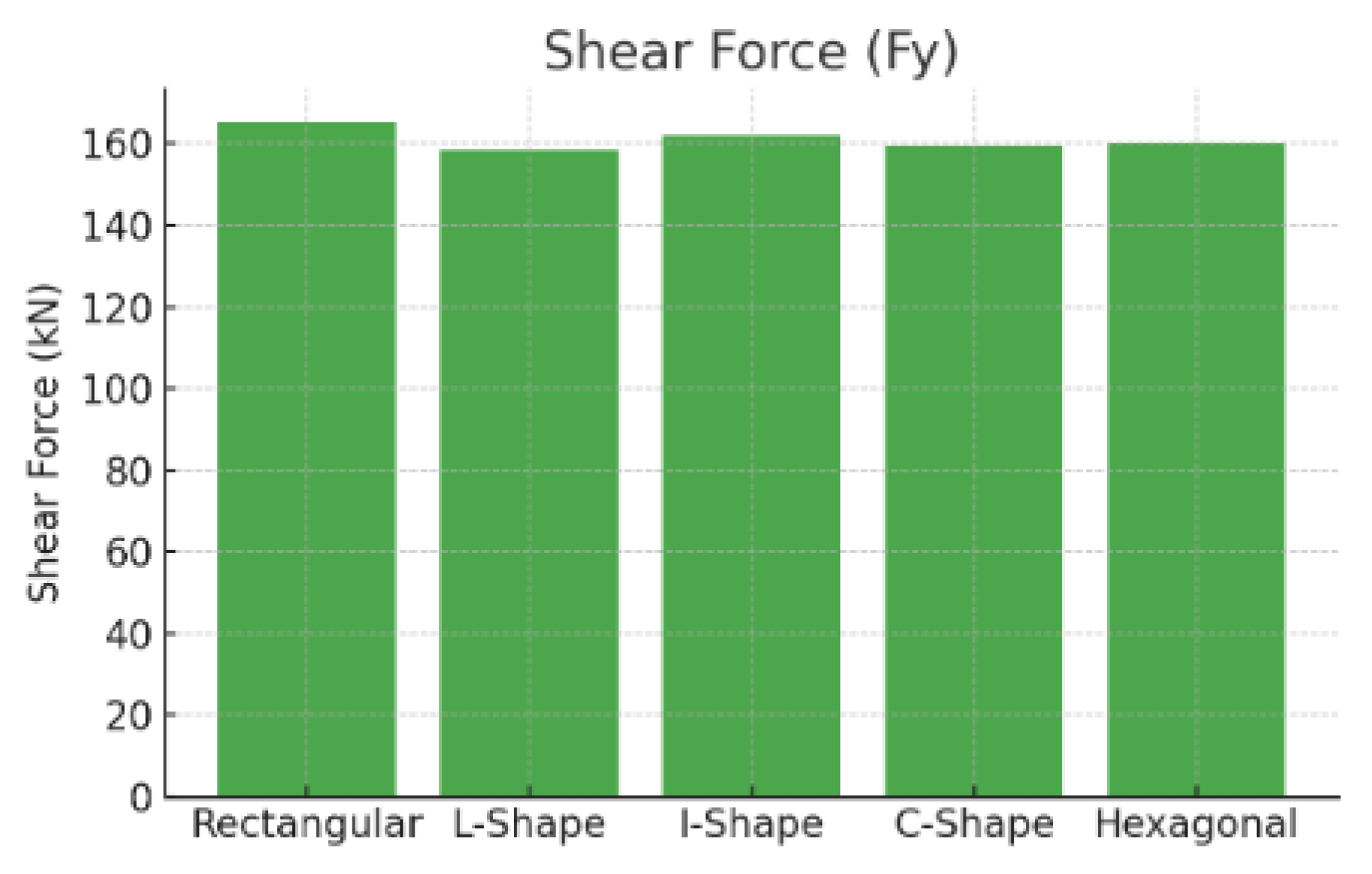
The Rectangular configuration has the highest shear force (165.3 kN), meaning it offers better resistance to lateral loads. The Hexagonal plan (160.05 kN) performs slightly lower than Rectangular but better than irregular shapes. The L-shape has the lowest shear resistance (158.4 kN), making it less suitable for high seismic loads. Symmetrical shapes (Rectangular and Hexagonal) distribute lateral loads more efficiently, while irregular shapes struggle with shear resistance.
Figure 14.
Storey Displacement comparison.
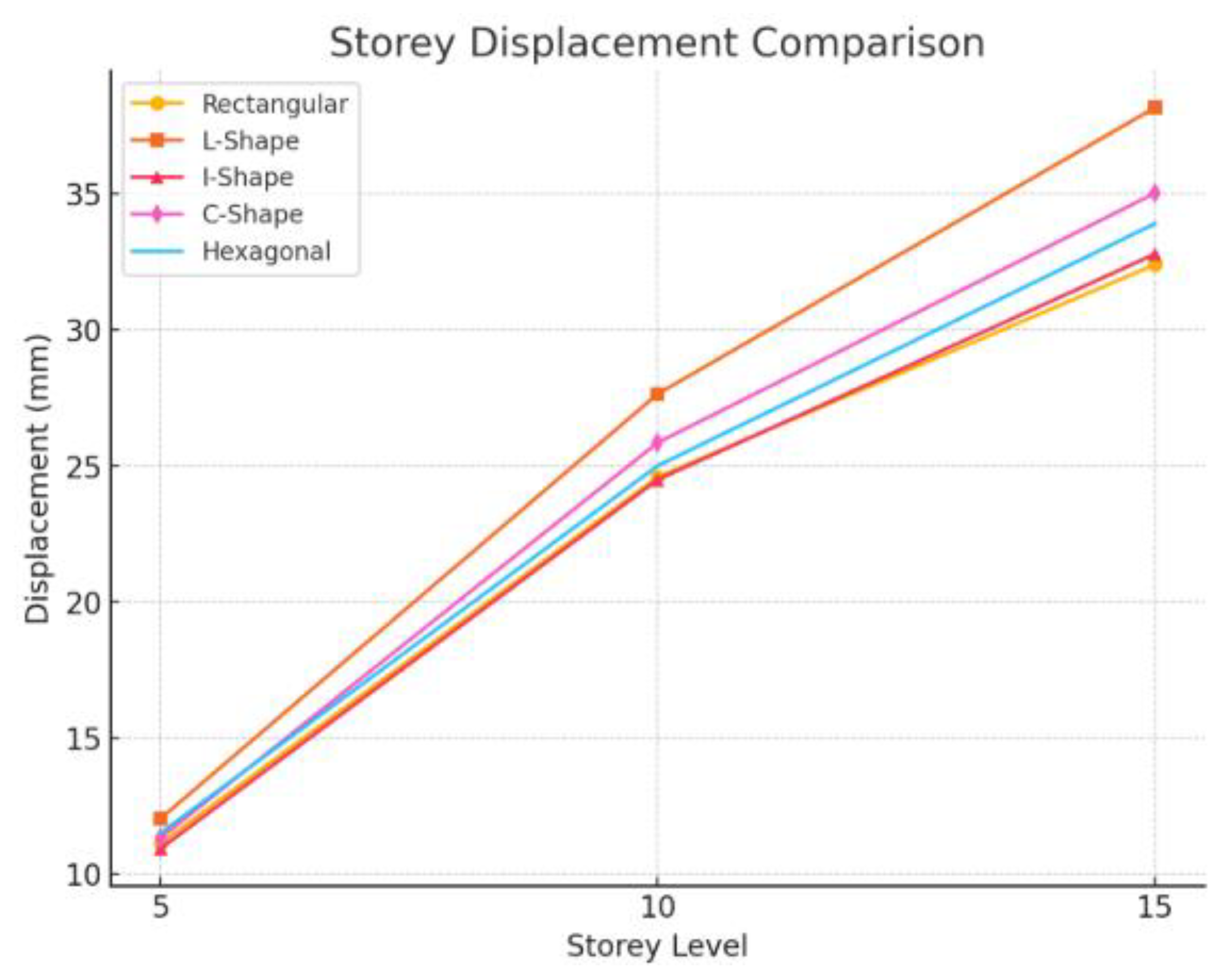
At 5th Storey L-shape building has the highest displacement (12.03 mm), meaning it is the weakest at this level. I-shape has the lowest displacement (10.93 mm), indicating better stiffness in the lower levels. Rectangular (11.12 mm), C-shape (11.32 mm), and Hexagonal (11.50 mm) perform similarly, with moderate displacement. Interpretation: At the 5th storey, irregular shapes (L-shape) already begin to show higher displacement, which may lead to more instability as height increases. At 10th Storey L-shape again shows the highest displacement (27.64 mm), reinforcing its weaker lateral resistance. I-shape (24.49 mm) and Rectangular (24.59 mm) show the least displacement, meaning they maintain stiffness well. Hexagonal (25.00 mm) and C-shape (25.85 mm) have moderate displacement. Interpretation: Displacement increases with height for all structures, but L-shape experiences disproportionately high displacement, making it a poor choice in seismic areas. At 15th Storey L-shape has the maximum displacement (38.16 mm), making it the most unstable at the top levels-shape (35.02 mm) and Hexagonal (33.90 mm) also show significant displacement but perform better than L-shape. Rectangular (32.39 mm) and I-shape (32.78 mm) have the least displacement, confirming their stability. Interpretation: At the highest levels, L-shape and C-shape structures suffer from excessive lateral movement, which can cause discomfort and potential structural damage in high-rise buildings.
Figure 15.
Overturning Moment comparison.
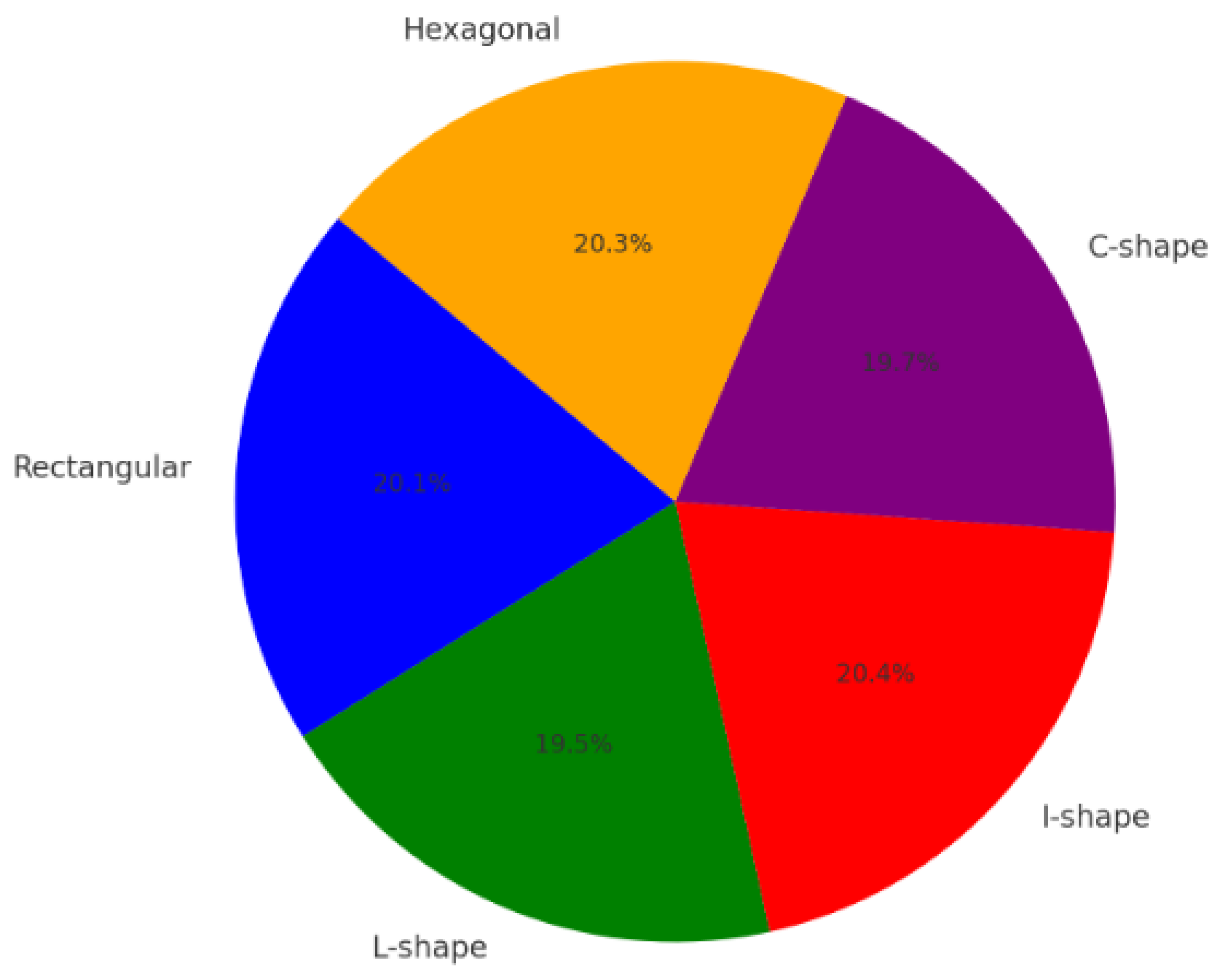
I-shape has the highest total overturning moment (20.4%), indicating that this shape experiences the greatest tendency to overturn due to lateral loads. Hexagonal and Rectangular shapes have similar overturning moments (~20.3% and 20.1%), suggesting comparable resistance to lateral forces. L-shape has the lowest overturning moment (19.5%), meaning it is relatively more stable against overturning compared to the other shapes. C-shape is slightly higher than L-shape (19.7%), but still lower than the I-shape, hexagonal, and rectangular structures.
5. Conclusions
The analysis of different plan configurations for a multi-storey RCC framed structure highlights the significant impact of building shape on structural performance. Rectangular buildings consistently exhibit the highest stability, with lower lateral displacements and greater resistance to storey shear and overturning moments. This makes them a preferred choice for high-rise structures. Irregular shapes such as L-shape, I-shape, and C-shape introduce structural weaknesses due to asymmetry, leading to higher lateral displacements and lower storey shear values. The study confirms that L-shape buildings experience the least storey shear, making them less suitable for high seismic activity areas. The newly introduced hexagonal plan configuration demonstrates moderate performance between the Rectangular and irregular shapes. Its symmetrical geometry contributes to better load distribution, reducing stress concentrations in key structural elements. The storey shear and lateral displacement values of the hexagonal shape remain better than L and C-shape buildings but slightly less efficient than the rectangular configuration. Overturning moments in the Hexagonal plan show greater stability than irregular configurations, indicating its potential as a viable alternative for earthquake-resistant structures. Based on these findings, symmetrical designs such as Rectangular and Hexagonal plans are more efficient and resilient under seismic and lateral loads. Future research can further optimize the hexagonal shape by modifying its aspect ratio, material properties, and load-bearing elements. Additionally, integrating advanced materials, base isolation techniques, and energy-absorbing dampers can enhance the seismic resistance of all configurations. These improvements will be essential in developing safer and more efficient high-rise structures, especially in earthquake-prone regions.
Conflict of interest
Authors declare no conflict of interest
References
- Zhuo Song, Xiaojun Li, Yushi Wang, Bochang Zhou, Amplitude-Scaling Bias Analysis of Ground Motion Record Set in Strip Method for Structural Seismic Fragility Assessment, Buildings, 10.3390/buildings15030401, 15, 3, (401), (2025).
- Mao-Xin Wang, Gang Wang, Deep neural network-powered ground-motion models for acceleration spectrum intensity, Housner's spectrum intensity, and displacement spectrum intensity, SSRN Electronic Journal, 10.2139/ssrn.5024578, (2025).
- Lin, Ting and Baker, Jack W., "Introducing Adaptive Incremental Dynamic Analysis: A New Tool for Linking Ground Motion Selection and Structural Response Assessment" (2013). Civil and Environmental Engineering Faculty Research and Publications. 40. https://epublications.marquette.edu/civengin_fac/40.
- Roohi, M.; Hernandez, E.M. Performance-based post-earthquake decision making for instrumented buildings. J. Civ. Struct. Heal. Monit. 2020, 10, 775–792. [CrossRef]
- Papazafeiropoulos, G., & Plevris, V. (2023). Kahramanmaraş—Gaziantep, Türkiye Mw 7.8 Earthquake on 6 February 2023: Strong Ground Motion and Building Response Estimations. Buildings, 13(5), 1194. [CrossRef]
- Miyamoto, Kit H. and Sechi, Giulia Jole and Victor, Guilaine and St Come, Beverly and Broughton, Mark and Gilani, Amir S. J., Haiti Earthquake 2021: Findings from the Repair and Damage Assessment of 179,800 Buildings. Available at SSRN: https://ssrn.com/abstract=4421106 or. [CrossRef]
- Xiaolei Wang, Ximing Wang, Correlation Between Generalized Intensity Measures of Vertical Ground Motions, Journal of Earthquake Engineering, (1-18), (2025). [CrossRef]
- Pouyan Fakharian, Hosein Naderpour, Mohammad Kazem Sharbatdar, Seyed Hooman Ghasemi, Development of a New Method for Strong Ground Motion Selection Considering Joint Probability Distribution, Journal of Structural Design and Construction Practice, 30, 1, (2025). [CrossRef]
- Simone D’Amore, Stefano Pampanin, Displacement-based seismic retrofit of reinforced concrete buildings through low-damage exoskeletons, Engineering Structures, 322, (119209), (2025). [CrossRef]
- L. G. Pujades, Y. F. Vargas-Alzate, N. Lantada, R. González-Drigo, Probabilistic parametric analysis of capacity, fragility and expected seismic damage of framed reinforced concrete buildings, Bulletin of Earthquake Engineering, (2025). [CrossRef]
- Kiani, J., & Pezeshk, S. (2017). Sensitivity analysis of the seismic demands of RC moment resisting frames to different aspects of ground motions. Earthquake Engineering and Structural Dynamics, 46 (15), 2739-2755. [CrossRef]
- Guleria, A. (2014). Structural Analysis of a Multi-Storeyed Building using ETABS for Different Plan Configurations. International Journal of Engineering Research & Technology (IJERT), 3(5).
- Mohiuddin, H., & Khan, R. (2018). Dynamic Analysis of RCC Multi-Storey Framed Structure with Different Plan Configurations. International Journal of Engineering Research and Applications, 8(9), 21-26. https://www.researchgate.net/publication/327905456_Dynamic_Analysis_of_RCC_Multi-Storey_Framed_Structure_with_Different_Plan_Configurations.
- Sharma, A., & Goyal, R. (2019). Seismic Analysis of Different Shaped Building Structures using ETABS. International Journal of Recent Technology and Engineering, 8(3), 1234-1240. [CrossRef]
- Patel, P., & Shah, M. (2017). Analysis of Multi-Storey RCC Frames of Regular and Irregular Plan Configurations under Seismic Condition. SSRG International Journal of Civil Engineering, 4(6), 45-52. https://www.internationaljournalssrg.org/IJCE/2017/Volume4-Issue6/IJCE-V4I6P112.pdf.
- Kumar, S., & Singh, Y. (2016). Effect of Different Column Shapes on Seismic Performance of Buildings. International Journal of Research in Engineering and Technology, 5(12), 56-62. https://ijrest.net/old_website/downloads/volume-3/issue-12/pid-ijrest-312201616.pdf.
- Khan, S., & Jaiswal, O. R. (2019). Seismic Performance of L-Shape, U-Shape RC Buildings with and without Shear Wall. International Research Journal of Engineering and Technology (IRJET), 6(2), 1123-1130. https://www.irjet.net/archives/V9/i2/IRJET-V9I287.pdf.
- Patil, S., & Kumbhar, P. D. (2022). Dynamic Analysis of Multistorey RCC Building with Different Plan Configurations. International Journal for Research Trends and Innovation (IJRTI), 7(8), 789-795. https://ijrti.org/papers/IJRTI2208156.pdf.
- Sharma, R., & Patel, P. (2020). Seismic Performance of RC Structure by Considering Different Orientation and Classes. International Journal for Research in Applied Science and Engineering Technology (IJRASET), 8(7), 1456-1463. [CrossRef]
Disclaimer/Publisher’s Note: The statements, opinions and data contained in all publications are solely those of the individual author(s) and contributor(s) and not of MDPI and/or the editor(s). MDPI and/or the editor(s) disclaim responsibility for any injury to people or property resulting from any ideas, methods, instructions or products referred to in the content. |
© 2025 by the authors. Licensee MDPI, Basel, Switzerland. This article is an open access article distributed under the terms and conditions of the Creative Commons Attribution (CC BY) license (http://creativecommons.org/licenses/by/4.0/).
Copyright: This open access article is published under a Creative Commons CC BY 4.0 license, which permit the free download, distribution, and reuse, provided that the author and preprint are cited in any reuse.


