
Submitted:
25 March 2025
Posted:
26 March 2025
You are already at the latest version
Abstract
The current work is devoted to the problem of the stability of the top-slewing tower cranes concerning the wind. A sufficiently strong wind can cause the overturning of the whole crane. The critical wind speed varies significantly depending on the geometrical configuration of the crane with respect to the wind direction. At the very beginning, the aerodynamic forces are estimated using CFD simulations. Next, the obtained results are compared with the applicable standards. The critical wind speeds and corresponding jib rotation angles are determined for two selected crane configuration variants: crane without payload and crane with maximal payload located at the end of the jib. It occurred that the critical wind speed varies between 35m/s and 53m/s depending on the assumed variant. Moreover, the trace of the gravity center is also determined to validate the obtained results.
Keywords:
slewing tower crane
; wind load
; CFD simulation
; crane overturning
; truss structure
; a trace of gravity center
1. Introduction
The current work continues our efforts to estimate the critical wind speed causing the overturning of the tower cranes of a different kind. In the first one [1], the sectional models of the tower and jib lattice were experimentally studied in the aerodynamic tunnel to determine the magnitude of the aerodynamic forces, mainly the drag component, acting on the structure. Next, the appropriate CFD simulations were carried out. The results obtained reveal good agreement. The obtained results were adopted to evaluate the critical wind speed causing the tip-over of the bottom-slewing crane [2] (fast-erecting 63k crane by Liebherr) in a different configuration. The results (wind speed) were confronted with the different codes and standards. In the current work, the proposed method is applied in the case of a quite different structure, namely a top-slewing tower crane. First, this kind of crane is much bigger than bottom-slewing one, which was previously investigated. Moreover, in the case of the top-slewing crane, the tower does not rotate during the work. Thus, the generated aerodynamic drag forces are slightly different than in the previous case.
One of the most dangerous and devastating catastrophes connected with tower cranes is their overturning. Such a catastrophe can be caused by different reasons, for example, a faulty foundation or exceeding the permissible weight of the payload. However, due to rapid changes in weather conditions, namely increasing wind speed and, in consequence, its gusts, the problem of the tower cranes overturning becomes critical. Such a catastrophe took place in Cracow (Poland) on 17th February 2022 [3]. According to the weather forecast, the expected wind speed did not exceed 90 km/h that day [4,5]. However, locally, the wind or even a small tornado was much stronger, and its influence was limited. This is another reason why the wind phenomenon in a natural environment should be treated as very complex. The character of the wind is dynamic, accompanied by, for example, a sudden change in direction, turbulence, and strong gusts. The sudden gusts of wind are especially dangerous because they can be over two times stronger than the mean wind speed. It is estimated that the mean frequency of the gusts of wind is about 1Hz [6]. However, in different codes and standards, the wind load acting on the external surface of the structures is treated as static [7,8,9,10,11,12].
The periodically repeated gusts of wind induce the vibrations of the slender lattice structures, like tower cranes of different sizes and shapes. It can lead to the fatigue failure of the high-tension parts of the crane structure, which possess very low damping properties [13]. Moreover, wind excitation has a rather random character, thus, the analysis of such a phenomenon is rather difficult [14]. Jiang and Li [15] applied the finite element method and a linear autoregressive model to simulate the time history of multidimensional fluctuating wind samples. It reveals that the structural strength is sufficient for the wind speed equal to 20 m/s. Next, Chen et al. [16] show that the most dangerous position of the horizontal jib of the tower crane differs from the strictly perpendicular position concerning the wind direction. The so-called galloping vibration of the crane devices, induced by wind, can cause the tip-over of the whole structure. Thus, Oliveira and Correia [17], after an appropriate analysis using the finite element method, designed an advanced active vibration damping system. This system should protect the crane from overturning. Oliveira and Correia [18] studied the dynamic response of two different tower cranes caused by seismic and wind excitation. It is worth stressing here that quite different problems are concerned with the tower cranes, which are outer-attached during the construction process of the tall and super-tall buildings [19,20]. Finally, Ghazwani et al. [21] propose an advanced technique for increasing the stability of the tower crane during cyclones through modal analysis. They use the finite element method. For this, modal analysis of a jib, mast, and tower crane is performed individually to minimize the tuning effect of natural frequency.
A quite different problem caused by the strong wind is the possibility of overturning the crane device. Such an accident is mentioned at the beginning of this section. It is a particularly dangerous situation because of the possibility of killed persons and/or significant material losses. It should be noted here that the papers concerning such problems are rather rare. Here can be quoted the following works, namely: tip-over of the gantry container crane with payload [22], tip-over of the gantry cranes [23,24,25,26], tip-over of the scissor lift [27], or tower cranes [28].
To summarize the above brief survey of literature it is worth quoting several papers concerning the problem of the interference effect between tower cranes and surrounding buildings. Chen et al. [29] perform CFD analysis of the interference effect between a single building and the QTZ125 tower crane. They studied different locations of the crane relative to the building and different wind directions. The turbulent flow of the air is modeled using the k-ε estimation. Voisin et al. [30] carried out the test of the 1/80 scaled model of the Potain MD238 in a boundary layer aerodynamic tunnel. Two environmental conditions (with and without an upwind surrounding the building) are tested to analyze the wind field's influence on the tower crane's behavior. Overturning moments at the base crane level are identified and evaluated. It is observed that inertial and centrifugal moments are much smaller in comparison to gravity and wind moments. Next, Chen et al. [31] carried out a numerical simulation using CFD to study the mean force and moment coefficients of an in-service tower crane at five different locations concerning the building being under construction. A single, unattached tower crane was taken as the reference counterpart. Wang et al. [32] perform the buffeting analysis of the tower crane, which is attached to the Ma’anshan Yangtze River bridge in China pylon. The structural buffeting calculation is carried out in the modal space and the frequency domain. This analysis includes aerodynamic damping and stiffness effects due to structural movement or vibration induced by the wind. The aerodynamic characteristic of the outer-attached to bridge pylons with variable cross-sections is usually complex, making it hard for accurate buffeting comfort assessment of cranes. An architecture of buffeting analysis of tower cranes is proposed by modifying Davenport quasi-steady buffeting forces for cranes considering the variation of aerodynamic sections of pylon-crane systems.
The interference effect is present not only in the case of buildings but also between other structures that are exposed to the wind. Here can be quoted works concerning interference effects between different antennas [33,34,35], scaffoldings [36], or large cooling towers [30,31].
Currently, we are studying the influence of the wind on the relatively large top-slewing tower crane. The investigated model of the top-slewing tower crane is based on the 71 EC-B5 crane by Liebherr. We intend to determine the most dangerous crane configuration (with payload and without) and the critical wind speed causing the tip-over of the whole structure. To solve the problem, we will apply the previously obtained results. The CFD simulations will be carried out of the studied structure on a real scale for different wind profiles.
2. Materials and Methods
2.1. Object of Analysis
The model of crane geometry is based on the top-slewing 71 EC-B5 crane by Liebherr. The investigated model of the crane is shown in Figure 1.
The total height of the crane is equal to Hcrane = 38.805 m, and the operating range of the jib is equal to Ljib = 50 m. It is assumed the following configuration of the studied crane. The crane's base is 3.8x3.8 m cross beam loaded with a central ballast of 60 tons, while the counterweight ballast is 9.75 tons. The crane jib consists of 7 lattice parts. The structure of the jib is shown in Figure 2. In such a configuration, the total capacity of the crane is equal to 4 tons at a distance of 20 m from the tower and 1 ton at the end of the jib. The investigated tower crane should be treated only as an example of this structure. Moreover, it doesn't correspond to the crane that had an accident in Cracow [3]. Thus, the current work is not an expert opinion or any expertise.
It is assumed the following geometrical configuration of the studied tower crane: 3 parts of the tower (T) of length 11.7 m, the counter jib of length 10.94 m, slewing platform (S) of length 2.43 m, and the following parts of the jib, one part (1) 9.85 m, two parts (2) 5 m, one part (3) 10 m, one part (4) 2,5 m, one part (5) 7,5 m, one part (6) 5 m, one part (7) 10 m, and finally one part (8) of length 0.58 m. The height of cruciform base (K) is equal to 1.4 m (Figure 2).
The simplified model of the crane geometry was created with the use of the ANSYS Workbench 2022R2 module New Design Modeler. The geometry is simplified in such a manner so that further generation of the finite element mesh is effective or even possible. The simplifications are as follows. There are omitted ropes, hooks, crane jib rotation mechanisms, and a ladder inside the tower, enabling access to the operator's cabin. The shapes of the particular parts of the lattices, like beams, rods, and bars, are also simplified. The wider and narrower parts of the crane tower truss are connected directly. These parts do not overlap each other like in the case of a real structure. The dimensions of the transverse sections of some elements of the trusses are slightly changed to avoid problems and errors during automatic mesh generation. The detailed view of details of the simplified geometry of the studied crane is shown in Figure 3a-d.
2.2. Numerical Simulation
All CFD simulations are performed using the commercial package ANSYS Fluent R22. As mentioned above, the geometry of the crane is created in the Design Modeler module, and the tetrahedral mesh is generated in the Workbench’s module called “mesh”. The numerical simulations are performed for different geometrical configurations and three wind profiles: open, village, and urban terrain.
2.2.1. Domain and Boundary Conditions
As is shown in Figure 4a, the investigated tower crane is inside the cuboid filled with air. The geometrical dimensions of the cuboid are as follows: 230 m x 230 m, H = 90 m. Such dimensions are sufficiently large to avoid the impact of the boundary conditions on the results, meaning the aerodynamic forces and moments acting on the crane. One of the vertical walls of the cuboid plays the role of the inlet, and the opposite one is considered a pressure outlet. The air stream, which goes through the inlet, is formed according to the Davenport [7] wind profile, namely:
where Vg is wind speed measured at height zg. The value of the Vg = 15 m/s at height zg=40 m in all performed simulations is assumed. Exponent α depends on the terrain, namely 0.16, 0.28, and 0.4 for open, village, and urban terrain, respectively. The applied wind profiles as a function of space coordinate z are depicted in Figure 4b. The wind profiles are prescribed using an appropriate user-defined function (UDF). The intensity of the turbulence is assumed to be equal to 9% with the arbitrarily chosen length scale Lturb = 3.5 m.
The reference values of the wind speed, necessary for aerodynamic force and moment coefficients computations, are determined according to the following expression:
where V(z) is an appropriate wind profile described by equation (1). Reference wind speeds determined using Formula (2) are as follows: Vref = 12.924 m/s, 11.716 m/s, and 10.713 m/s for open, village, and urban terrain, respectively.
The top surface and both sides of the domain are movable with identical wind profiles as defined for the inlet. Finally, the ground and the tower crane are assumed to be stationary boundary conditions.
2.2.2. Investigated Configurations of the Tower Crane
It is assumed that the wind direction is parallel to the X-axis of the global Cartesian coordinate system, as shown in Figure 5. The configuration of the crane, namely, the position of the jib, is determined by the angle θ. For θ = 0°, the jib is positioned along the X-axis of the coordinate system. The simulations are performed for the following values of the angles θ, namely: θ = 0°, 15°, 30°, …, 90° for all wind profiles.
2.2.3. Model of Turbulent Flow and Properties of Air
According to the author's experience [26,27], if the dominant role plays the aerodynamic drag force and the component of aerodynamic force caused by viscosity is very small, the k-ε model with standard wall function provides a reasonable estimation of the aerodynamic force values. Moreover, it is not obligatory to create the special inflation layer of the cells on the surface of the boundary layer. For such a complicated structure as the studied crane, the creation of the inflation layers on each part of the crane leads to an enormous, unacceptably large number of finite cells. Thus, the choice of the k-ε model seems to be the only possibility. This model is also successfully used by other authors, for example, [16,20].
The standard air properties of the air on the sea level (temperature T = 15° C, ambient pressure p0 = 101,325.25 Pa) are assumed, namely kinematic viscosity ν = 1.7894 × 10⁻⁵ kg/(m∙s), density ρ = 1.225 kg/m3.
2.2.4. Finite Cell Mesh
As mentioned above, the mesh is automatically generated using the “mesh” module of the Workbench software. It is assumed that the mesh consists of tetrahedral-shaped cells. It is found that the creation of a proper mesh in the case of the investigated crane is possible for an approximate minimal face size of less than le = 0.025 m. Therefore, for further simulations, it is assumed that the minimal face size on the crane surfaces equals le = 0.02 m. To estimate the sensitivity of the numerical solution on the cell size, for the arbitrarily chosen crane configuration (θ = 90°) the simulations are carried out for the smaller cells, namely le = 0.0175 m and le = 0.015 m. The maximal size of the cells leMAX also varies correspondingly to le, and leMAX = 5.0 m, 4.5 m, and 4.0 m, respectively. It is worth noting that it is necessary to perform about 100 solver (pressure-based, steady state analysis) iterations to obtain a convergent solution. The obtained results are collected in Table 1. This table shows the aerodynamic force and moment coefficients, whose strict definition will be given later. The Mtip is an overturning moment causing the tip-over of the studied crane. Figure 5 shows the location of the tipping line. The overturning moment Mtip is determined concerning this line.
As can be observed, the represented results are very similar. The greatest values of the aerodynamic forces are obtained for le = 0.02 m. Therefore, it seems that the choice of le = 0.02 m and leMAX = 5.0 m ensures the appropriate accuracy of the calculations and safety of estimation. Moreover, the time of computations and necessary space on the hard disk is also optimal. In Figure 6, there are depicted details of the mesh on the surface of the studied crane.
3. Results of Numerical Simulations
Figure 7 represents the distribution of the static pressure on the surface of the crane structure induced by wind. This picture is for the urban wind profile (Vg = 15 m/s, zg = 40 m). The jib is perpendicular to the wind direction (θ = 90°). As can be observed, as the vertical coordinate Z (height) increases, the value of the static pressure also increases. This phenomenon is caused by the applied wind profile, where the value of the wind velocity depends on the height.
Figure 8a-d shows the components of the aerodynamic forces and overturning moment as a function of the angle θ. The most important component for further analysis is the Fx component because it causes the overturning of the whole structure. The maximal values are obtained for θ = 90°.
They are equal to Fx = 9220.826 N, 8480,169 N, and 7783.727 N in the case of open, village, and urban terrain. It is worth noting that in our previous work concerning other lattice structures (scissor lift or fast-erecting crane), the extreme values of the aerodynamic forces are obtained for a slightly different position of the structure for the wind direction. However, in the current study, the jib possesses a more openwork structure in comparison with the previously mentioned ones. The minimal values of the Fx components are obtained when the crane jib is parallel to the wind direction. In this case, the aerodynamic drag force is generated only by the tower (4274.746 N, 3571.366 N, and 2998.246 N, respectively). In turn, the component Fy, Figure 8b, takes maximal values for the angle θ close to the θ = 60°, and the values are as follows depending on the wind profile, namely: Fy = 1502.037 N, 1510.663 N, and 1478.181 N (absolute value). As can be seen, these values are very similar. It is caused by the fact that this component of the aerodynamic drag force is caused mainly by the rotating crane jib, while the crane tower is stationary. For the angles θ = 0°, 90°, 180°, and 270°, the value of Fy should be treated as equal to 0 N.
The Fz, Figure 8c, is one order of magnitude less in comparison with other components of the aerodynamic drag force. Thus, it can be omitted in further analysis.
Finally, the values of the overturning moments are depicted in Figure 8d. Similarly, as in the case of Fx, the maximal values of this quantity are reached for θ = 90°, and they are as follows: Mtip = 275.572 kNm, 266.554 kNm, and 256.794 kNm for the open, village, and urban terrain, respectively. The minimal values are obtained when the crane jib is parallel to the wind direction (90.862 kNm, 82.514 kNm, and 77.527 kNm).
The aerodynamic force and moment coefficients are presented in Table 2, Table 3, and Table 4. They are computed according to the below formulas, namely:
where ρ is the density of the air, Vref is a value of the reference wind speed computed according to formula (2), Aref denotes the reference area (Aref = 48.27 m²), and Bref is the reference overturning moment arm (Bref = 37.9 m).
4. Discussion
The results obtained from CFD simulations enable, among others, the estimation of the critical wind speed causing the tip-over of the crane. In other words, the maximal value of the wind speed below which the studied crane is stable is determined. The crane stability is a state when it can work safely. We have not investigated the loss of stability understood as a buckling phenomenon. To validate the CFD results, further computations are performed following applicable codes and standards. Firstly, the sum of the stabilizing and overturning moments with respect to the tipping line is determined. Next, according to the standard [7,8], the wind force acting on the crane is estimated based on the reference area of the lattice of the structure being in the same situation as in the CFD simulation. The analysis is carried out for two variants, namely 1) the jib with upper counterweight positioned against the wind direction and 2) in the direction of the wind. In the first case, the upper counterweight additionally stabilizes the whole crane. In the second case (rarely met in practice), the upper counterweight decreases the crane's stability. The computations are performed for urban terrain.
4.1. Variant 1. Determination of the Overturning and Stabilizing Moments
Based on the information contained in the catalog card of the tower crane and the technical and operational documentation regarding the dimensions and weights of the individual elements of the supporting structure, a diagram is made showing the system of forces acting on the crane structure concerning the most unfavorable tipping edge (Figure 9). W1 to W3 is the wind force at the corresponding height h1 to h3. The load resulting from the wind force will be presented later in the article.
According to the adopted system of forces, the overturning moments of the crane are calculated as the algebraic sum of the moments of the jib and load mass concerning the most unfavourable tipping edge. The values of forces and moments for variant 1 acting on the structure of the Liebherr 71 EC-B5 crane are presented in Table 5.
Based on the above data, the sum of overturning moments with a total value of Σ MO = 1203620 [Nm] = 1203.6 [kNm].
The stabilising moments of the real object are the sum of the moments resulting from the mass of the tower with turntable, counter-jib with counterweight, crosspiece and central ballast (Table 6).
Based on the obtained values of moments from component forces, the sum of stabilizing moments with a total value of Σ MS = 3245465 [Nm] = 3245.5 [kNm].
The calculations did not take into consideration the mass of such crane elements as the cabin, ropes, trolley rotation mechanism, etc. The effect of wind is also not taken into account, which will be presented in the next chapter. According to the standard, for the structure to be stable and the crane to maintain stability, the following condition must be met:
where: MS is the sum stabilizing moments; MO is the sum overturning moments:
Therefore, the stability condition of the top-slewing crane is met.
4.1. Variant 2. Determination of the Overturning and Stabilizing Moments
Generally, when the tower crane is not in service and the slewing platform device is not locked, the crane jib can rotate freely with the wind direction, as shown in Figure 9. The crane operator must unlock the slewing platform mechanism when the wind speed increases above 20 m/s. However, if the wind speed, measured at the jib level using a cup anemometer, is close to this value but does not exceed it, it is possible that the situation when the crane jib is in the position against the wind as depicted in Figure 10. It is also possible that the slewing platform mechanism is locked. This potentially means that the crane is in service, and the additional payload influences the crane's global balance.
In this case, the values of the overturning and stabilizing moments are shown in the tables below, Table 7 and Table 8. In Table 8, the sum of the overturning moments is shown using the bold font.
Based on the schemas of the mass distributions, shown in Figure 9 and Figure 10 for Variants 1 and Variants 2, the sums of the overturning and stabilizing moments are determined and collected in Table 9. In the further analysis, Variants 1 with payload (Case 1, Table 9) and the Variants 2 without payload (Case 4, Table 9) are considered.
4.2. The Wind Force Estimation According to the Standard
The obtained values of the overturning moments induced by the wind and estimated from the CFD simulations are compared with those that are computed according to the standard [7]. The estimations are based on the reference area Aref = 48.27 m2 of the crane lattice structure.
Utilizing the aerodynamic coefficients obtained from CFD results, the component values FX, FY of the aerodynamic forces are determined as a function of the wind speed V(z) according to formula (1).
Next, the overturning moment MO CFD 71EC-B is obtained as a function of the jib rotation angle θ, namely:
where . It makes possible the estimation of the critical wind speed causing overturning of the whole structure depending on the Case 1 or 4.
EuroCODE. To determine the wind force W according to the standard [7], the reference area Aref of the studied structure and the wind pressure distribution are needed. It is assumed that the wind speed is measured at the jib level, e.g., H = 40 m for the urban terrain. Because the wind speed changes (increases) together with height, the reference area of the whole structure Aref = 48.27 m² is divided into three parts, namely crane jib Aref_1 = 25.69 m², crane tower Aref_2 = 16.58 m², and upper counterweight Aref_3 = 6 m². Moreover, different standards assume that the load induced by the wind acting on the external surfaces of the structure is treated as a static normal pressure, with value p = 245 N/m² for wind speed equal to V = 20 m/s. Taken into account an appropriate proportion, in the current case (Vg = 15 m/s at height H = 40 m) the aerodynamic forces take the following values, namely: W1 = 2159.40 N for Aref_1 and h1 = 38.46 m, W2 = 836.71 N, for Aref_2, h2 = 20.33 m, and W3 = 47.37 N for Aref_3, h3 = 2 m. The value of the force Wi can be estimated using the following formula:
and, in consequence, the moments:
where . It should be noted that the value of the aerodynamic force W3 is relatively small in comparison with the others, thus the component of the overturning moment induced by this force is omitted in further analysis. Additionally, force W3 acts on the relatively small height acting close to the extremely large mass of the low ballast.
The values of the overturning moment, Mo CFD 71EC-B as a function of the jib rotation angle θ (blue color) and the overturning moments MO EuroCODE90, taking into account the wind force for urban terrain (green color), are presented in Figure 11. It is a constant value, independent of the jib rotation. Case 2 (without payload) of the crane configuration is used to validate the results obtained from CFD simulations. In this figure, the stabilizing moment Ms (red line) is taken from Table 9.
The Maximum Wind Force
Figure 12a and b show the overturning moments MO as a function of wind speed and the jib rotation angle θ for Variant 1 with payload (case 1) and Variant 2 without payload (case 4). In these figures, there is also depicted the stabilizing moment MS. These figures should be treated as a comparison of the overturning and stabilizing moments, which are obtained from CFD simulations and estimations based on MO EuroCODE90° for various wind speeds acting on the jib height at h1 = 38.46 m. Moreover, these figures are used to determine the critical wind speed and the jib rotation angle θ to the wind direction, which causes the tip-over of the whole crane. In other words, when the crane loses its stability.
Considering the above-presented results, it is possible to estimate the characteristics of the overturning moment as a dependency of the wind speed for the jib rotation angle θ = ±75 °, with the maximum payload at the end of the jib as well as for θ = ±75 ° without payload at all. The obtained relations are depicted in Figure 13.
4.3. Trace of the Gravity Center in the Example of the Tower Crane Liebherr 71EC-B5
Having prepared the values of the masses (weight of the structures) of the particular parts of the crane and the values of aerodynamic forces induced by wind, the trace of the gravity center can be determined. It helps to visualize the stability of the whole crane concerning the tipping lines. At the beginning, the total sum of the overturning and stabilizing moments with respect to the rotation axis of the jib must be computed. It makes it possible to determine the position of the center of gravity between the tipping edges. The tipping edges create a rectangle whose vertices are the axis of the supports. The crane loses stability when the center of gravity exceeds the tipping line. The example of the top-slewing tower crane (with and without payload) and the wind direction is shown in Figure 14. In this figure, the crane is in the most unfavorable configuration, similar to the case of the crane in Figure 9.
According to the assumed system of forces acting on the studied crane, the algebraic sum of the overturning moments (induced by the weight of the particular parts and payload at the end of the jib) is computed. The values of forces and moments acting on the studied structure are collected in Table 11. From the above data, the sum of overturning moments with a total value of Σ MOt = 1,333,545 [Nm] = 1333.55 [kNm] is obtained.
The stabilizing moments of the real object are the sum of the moments resulting from the tower mass with the turntable, counter-jib with counterweight, crosspiece, and central ballast (Table 12).
The sum of the stabilizing moments with the total value of: Σ MSt = 1,973,842 [Nm] = 1973.8 [kNm] was obtained, based on the obtained values of moments from the component forces. In the calculations, similarly to the calculations of the static work of the crane, the mass of such crane elements as the cabin, ropes, the rotation mechanism of the trolley travel, etc. is not taken into account. According to the standards, the condition of the stability is defined as, namely:
where: MSt is the sum stabilizing moments; MOt is the sum overturning moments:
Thus, the condition (6) is satisfied. The trace of the gravity center can be defined as follows the perpendicular projection of the gravity center on the plane perpendicular to the axis of the jib rotation limited by the four tipping edges. The geometrical dimensions of such a rectangle are determined by the crane support. It is assumed that the crane tip-over is possible concerning the edge, which is opposite to the wind direction as is shown in Figure 16. Moreover, the constant wind direction is assumed. The crane jib can rotate about its axis by the angle θ. The two following cases are investigated, namely: the crane does not carry the payload, and the crane carries the maximal payload Q1=1000 kg.
The trace of the gravity center creates a closed contour, where each point relates to the jib rotation angle θ. The curve describing the trace of the gravity center can be defined utilizing the concept of the guiding ray. Below are shown the formulas determining the guiding ray in the case, when the wind does not blow (rc), and in the case, when the wind is blowing (rcw). In both cases, the guiding ray is determined by its coordinates, and the coordinates xc, yc and xcw, ycw define the guiding ray:
where:
and the trace of the center of gravity at the time of the wind rcw:
where:
where: i is the index of a mass shown in Table 11 and Table 12. The obtained contours are presented below in Figure 15a and Figure 15b. In the first case (Figure 15a) the crane carries the maximal payload at the end of the crane jib (case 1). In the second case (Figure 15b) the crane carries no payload (case 4).
5. Conclusions
Based on the CFD analysis results, the aerodynamic force coefficients Cx and Cy are calculated. These coefficients allow for estimating the magnitude of the aerodynamic forces acting on the examined structure of the top-slewing tower crane as a function of the average wind speed. An example of such a structure is the Liebherr 71EC-B crane, which features a flat top. This structure allows a maximum payload of 1000 kg at the end of a 50 m jib length.
The obtained results are compared with the applicable standard [7]. This standard concerns the estimation of the wind load of the cranes, openwork construction, and lattice structures. The determination of the wind force is based on the so-called reference area Aref and the static pressure distribution induced by the blowing wind. The estimation is done concerning the most unfavorable crane configuration to the tippling line and the wind direction. In our case, it relates to the crane configuration for θ = 90°.
Next, the total (resultant) stabilizing and overturning moments are determined concerning the selected tipping line for the exemplary top-slewing tower crane 71EC-B. The four cases are possible. In the first case, the jib is parallel to the wind direction without payload, and the upper counterweight is against the wind. The second case is similar, but the jib carries a payload. Both these cases relate to when the crane is out of service and the slewing platform is unlocked. The third case is when the jib is parallel to the wind direction without payload; however, the upper counterweight is on the opposite side than in the previous cases. Consequently, in the fourth case, the jib is in an identical geometrical configuration as the previous one but now carries a payload. The third and fourth cases relate to when the crane is in service and the slewing platform is locked. The second and third cases are chosen for further analysis.
Having prepared the values of the aerodynamic forces induced by the wind obtained from the CFD analysis and computed according to EuroCODE, the characteristics of the overturning moment for both investigated variants are shown. These characteristics are the function of the jib rotation angle θ for the wind speed with increment value 5 m/s. The range of the dangerous jib rotation angle for which the studied crane loses its stability (for both cases) is determined. The specified range of angle θ shows dangerous angles due to loss of crane stability for both variants of the jib setting and θ = ±75° (the least favourable). For these values of the angle θ, when the crane loses its stability and is close to tipping over, the wind speed value equals 35 m/s.
For better-studied problem visualization, the trace of the center gravity with wind forces taken into account is created using an analytical approach. The results are shown on the appropriate graphs, where the tipping edges are marked.
The work shows that the approach based solely on the Mo < Ms condition according to EuroCODE does not take into account the change in the angle of the jib rotation to the wind direction and, consequently, the change in its reference area Aref(θ), an example of which is the angle of ±75°, for which the value of the wind force is the greatest. This approach defines one location of the jib for the angle θ = 0° for variant 1 or 90° for variant 2 where θ = 90°, and in both cases, we have Aref corresponding to the area for the angle θ = 90°.
In summary, the described analytical approach, taking into account the jib rotation angle θ, specifies the values of moments acting on the crane structure with the simultaneous action of the wind force on this system. Having the values of Fx i Fy as a function of jib rotation angle θ, it is possible to specify the approach based on the EuroCODE. Moreover, more accurate results are obtained using the method based on the determination of the trace of the gravity center
The obtained results are in relatively good agreement with the wind conditions that caused the catastrophe of the tower crane in Cracow, mentioned in the introduction.
Author Contributions
Conceptualization, M.A.; methodology, M.A. and M.B.; software, M.A. and M.B; validation, M.A. and M.B.; numerical analysis, M.B.; experimental investigation, M.A.; data curation, M.A. and M.B.; writing—original draft preparation, M.A. and M.B.; writing—review and editing, M.A. and M.B.; visualization, M.A. and M.B. All authors have read and agreed to the published version of the manuscript.
Funding
This research received no external funding.
Institutional Review Board Statement
Not applicable.
Informed Consent Statement
Not applicable.
Data Availability Statement
The original contributions presented in the study are included in the article, further inquiries can be directed to the corresponding author.
Conflicts of Interest
The authors declare no conflicts of interest.
References
- Augustyn, M.; Barski, M.; Chwał, M.; Stawiarski, A. Experimental and Numerical Estimation of the Aerodynamic Forces Induced by the Wind Acting on a Fast-Erecting Crane. Appl. Sci. 2023, 13, 10826. [Google Scholar] [CrossRef]
- Augustyn, M.; Barski, M. Numerical and Analytical Estimation of the Wind Speed Causing Overturning of the Fast-Erecting Crane – part II. Appl. Sci. 2024, 14, 4694 doiorg/103390/app14114694. [Google Scholar] [CrossRef]
- Release from the Press Office of the Institute of Meteorology and Water Management, Warsaw, 16 February 2022. Available online: https://danepubliczne.imgw.pl/data/arch/ost_meteo/2022/ (accessed on 13 January 2025).
- Wiosło, M.; , Grochot, A. The gale overturned a crane in Krakow. Two people are dead, RMF24, 2022. Available online: https://www.rmf24.pl/regiony/krakow/news-wichura-przewrocila-dzwig-w-krakowie-dwie-osoby-nie-zyja-fil,nId,5838306#crp_state=1 (accessed on 13 January 2025).
- Ciryt, B.; Fatal accident at the construction site of the court in Wieliczka. The crane fell onto an employee's container, and one person died. Watch the video, Wieliczka Nasze Miasto. 2023. Available online: https://wieliczka.naszemiasto.pl/smiertelny-wypadek-na-budowie-sadu-w-wieliczce-dzwig/ar/c1-9511255 (accessed on 13 January 2025).
- König, G.; Zilch, K.; Lappas, G. Wind loading of shipyard gantry cranes—A comparison of full-scale measurement, wind tunnel test and gust factor approach, Wind Engineering. In Proceedings of the Fifth International Conference, Fort Collins, CO, USA, 8–13 July 1979; Volume 2, pp. 911–923. [Google Scholar]
- ISO 4302:2016 EN; Cranes-Wind Load Assessment. ISO Copyright Office: Geneva, Switzerland, 2016.
- ISO-8686-1:2012 Cranes.
- JIS B 8830-2001; Cranes-Wind Assessment. Japanese Industrial Standards Committee: Tokyo, Japan, 2001.
- BS 2573-1; British Standard. Rules for the Design of Cranes Part 1: Specifications for Classification, Stress Calculations, and Design Criteria for Structures (4th Revision). BSI: San Jose, CA, USA, 1983.
- GB/T 3811-2008; Design Rules for Cranes. General Administration of Quality Supervision. Inspection and Quarantine of the People’s Republic of China: Beijing, China, 2008.
- ASCE. Minimum Design Loads and Associated Criteria for Buildings and Other Structures; ASCE 7: Reston, VA, USA, 2016. [Google Scholar]
- Klinger, C. Failures of cranes due to wind induced vibrations. Eng. Fail. Anal. 2014, 43, 198–220. [Google Scholar] [CrossRef]
- Jiang, H.; Li, S. The Wind-Induced Vibration Response for Tower Crane Based on Virtual Excitation Method. The Open Mechanical Engineering Journal 2014, 8, 201–205. [Google Scholar] [CrossRef]
- Jiang, H.; Li, Y. Dynamic Reliability Analysis of Tower Crane with Wind Loading. IOP Conf. Ser. Mater. Sci. Eng. 2019, 677, 052031. [Google Scholar] [CrossRef]
- Chen, W.; Qin, X.R.; Yang, Z.; Zhan, P. Wind-induced tower crane vibration and safety evaluation. J. Low Freq. Noise Vib. Act. Control. 2020, 39, 297–312. [Google Scholar]
- Hechmi El Ouni, M.; Ben Kahla, N.; Islam, S.; Jameel, M. A Smart Tower Crane to Mitigate Turbulent Wind Loads. Struct. Eng. Int. 2021, 31, 18–29. [Google Scholar] [CrossRef]
- Oliveira, S.C.; Correia, P.M.B. Comparison of the seismic and wind analyses of two tower cranes. Journal of Vibroengineering 2021, 23(4), 956–975. [Google Scholar] [CrossRef]
- Lu, Y.; Zhang, L.; He, Z.; Feng, F.; Pan, F. Wind-induced vibration fragility of outer-attached tower crane to super-tall buildings: A case study. Wind and Structures 2021, 32(5), 405–421. [Google Scholar]
- Lu, Y.; Gao, M.; Liang, T.; He, Z.; Feng, F.; Pan, F. Wind-induced vibration assessment of tower cranes attached to high-rise buildings under construction, Automat. Constr. 2022, 135, 104132. [Google Scholar]
- Ghazwani, M.H.; Alnujaie, A.H.; Chandravanshi, M.L.; Deepak, D.; Singh, C.; Kumar, M. Failure analysis of tower crane using FEM and theoretical studies. Yanbu Journal of Engineering Science 2022, 19, 1–20. [Google Scholar] [CrossRef]
- Lee, S.W.; Shim, J.J; Han, D.S.; Han, G.J.; Lee, K.S. An Experimental Analysis of the Effect of Wind Load on the Stability of a Container Crane. J. Mech. Sci. Technol. 2007, 21, 448–454. [Google Scholar]
- Frendo, F. Gantry crane derailment and collapse induced by wind load. Eng. Fail. Anal. 2016, 66, 479–488. [Google Scholar] [CrossRef]
- Wu, X.; Sun, Y.; Wu, Y.; Su, N.; Peng, S. The Interference Effect of Wind Load and Wind-Induced Dynamic Response of Quayside Container Cranes. Appl Sci 2022, 12, 10969. [Google Scholar]
- Su, J.-C.; Li, L.; Chan, P.W.; Zhou, Q.-J.; Yang, H.-L. Numerical simulation research on the overturning of gantry crane by downbursts. Heliyon 2023, 9, e18641. [Google Scholar]
- Augustyn, M.; Barski, M. Estimation of the Wind Load Required to Cause the Overturning of a Gantry Crane, Comparing Different Structures of the Main Horizontal Girder. Appl. Sci. 2024, 14(3), 1092. [Google Scholar] [CrossRef]
- Augustyn, M.; Barski, M.; Chwał, M.; Stawiarski, A. Numerical and Experimental Determination of the Wind Speed Value Causing Catastrophe of the Scissor Lift. Appl. Sci. 2023, 13, 3528. [Google Scholar] [CrossRef]
- Hebiba, A.M.; Bouferguene, A.; Moon, S.; Han, S. Wind-Wise Automated Stability Analysis for Selection of Tower Crane and Location. J. Constr. Eng. Manage 2022, 148(11), 04022127. [Google Scholar] [CrossRef]
- Chen, W.; Qin, X.; Yang, Z. Study of the interference effect of building on the along-wind load of tower crane. In Proceedings of the 2019 International Conference on Advances in Construction Machinery and Vehicle Engineering, Changsha, China, 14-16 May 2019. [Google Scholar]
- Voisin, D.; Grillaud, G.; Solliec, C.; Beley-Sayettat, A.; Berlaud, J.L.; Miton, A. Wind tunnel test method to study out-of-service tower crane behaviour in storm winds. J. Wind Eng. Ind. Aerodyn. 2004, 92, 687–697. [Google Scholar]
- Chen, W.; Qin, X.; Yang, Z. Effects of installation location the in-service wind load of a tower crane. Proceedings of the Institution of Civil Engineering – Structure and Buildings 2019, 173, 141–156. [Google Scholar]
- Wang, H.; Liu, Y.; Xu, Z.; Mao, J.; Li, B. Wind-induced buffeting comfort assessment of tower cranes considering the wake effect of super-high towers. J. Wind Eng. Ind. Aerodyn. 2023, 240, 105469. [Google Scholar] [CrossRef]
- Holmes, J.D.; Banks, R.W.; Roberts, G. Drag and aerodynamic interference on Microwave dish antennas and their supporting towers. J. Wind. Eng. Ind. Aerod. 1993, 50, 263–270. [Google Scholar] [CrossRef]
- Carril, C.F., Jr.; Isyumov, N.; Brasil, R.M.L.R.F. Experimental study of the wind forces on rectangular latticed communication towers with antennas. J. Wind. Eng. Ind. Aerod. 2003, 91, 1007–1022. [Google Scholar]
- Martín, P.; Elena, V.; Loredo-Souz, A.M.; Camaño, E.B. Experimental study of the effects of dish antennas on the wind loading of telecommunication towers. J. Wind. Eng. Ind. Aerod. 2016, 149, 40–47. [Google Scholar] [CrossRef]
- Wang, F.; Tamura, Y.; Yoshida, A. Interference effect of a neighboring building on wind loads on scaffolding. J. Wind Eng. Ind. Aerodyn. 2014, 125, 1–12. [Google Scholar]
- Li, G.; Cao, W.B. Structural analysis and optimization of large cooling tower subjected to wind loads based on the iteration of pressure. Struct. Eng. Mech. 2013, 46, 735–753. [Google Scholar] [CrossRef]
- Ke, S.T.; Wang, H.; Ge, Y.J. Interference effect and the working mechanism of wind loads in super-large cooling towers under typical four-tower arrangements. J. Wind. Eng. Ind. Aerod. 2017, 170, 197–213. [Google Scholar] [CrossRef]
Figure 1.
Model of the geometry of the top-slewing construction tower crane.
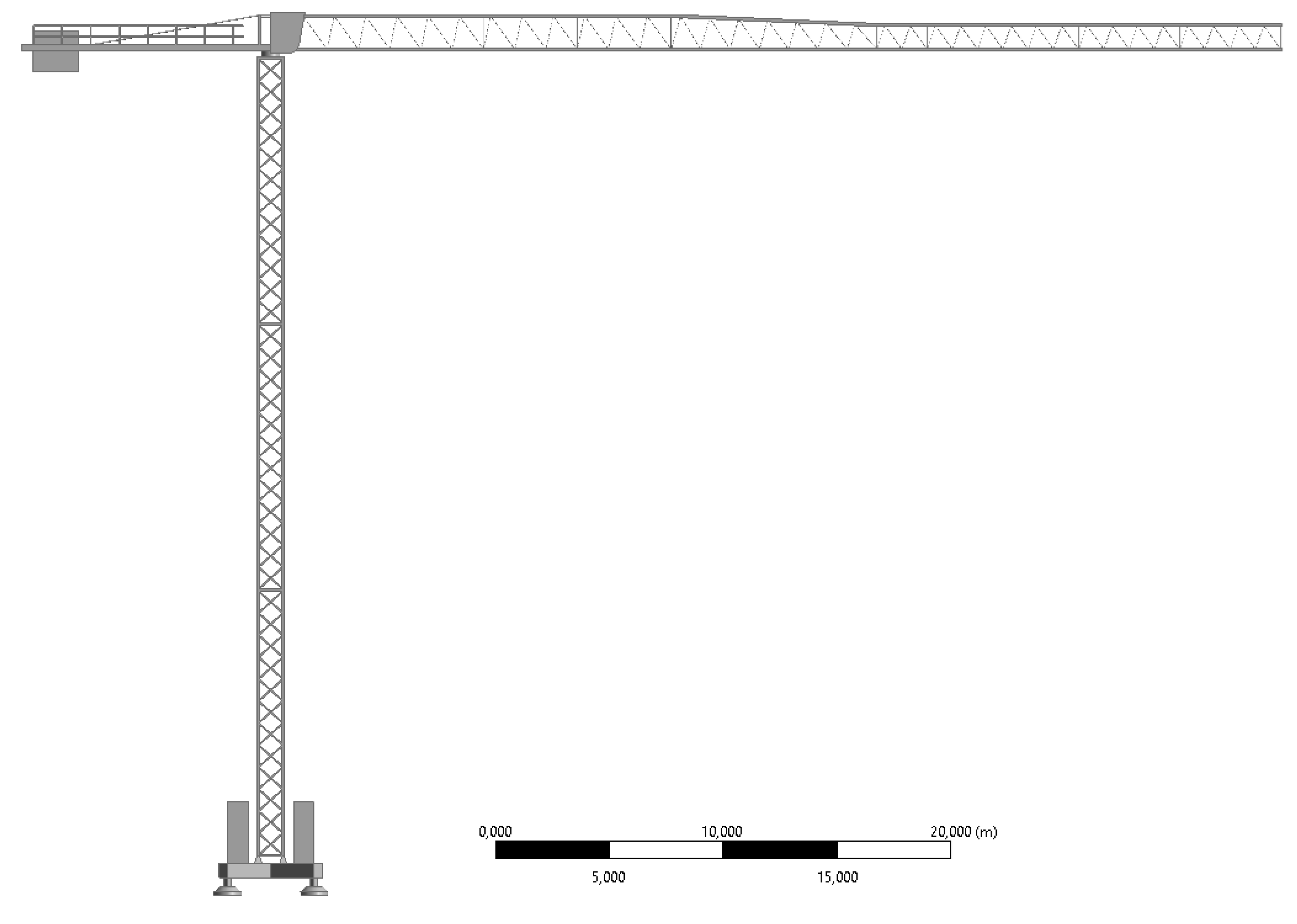
Figure 2.
Configuration of the crane jib and tower.
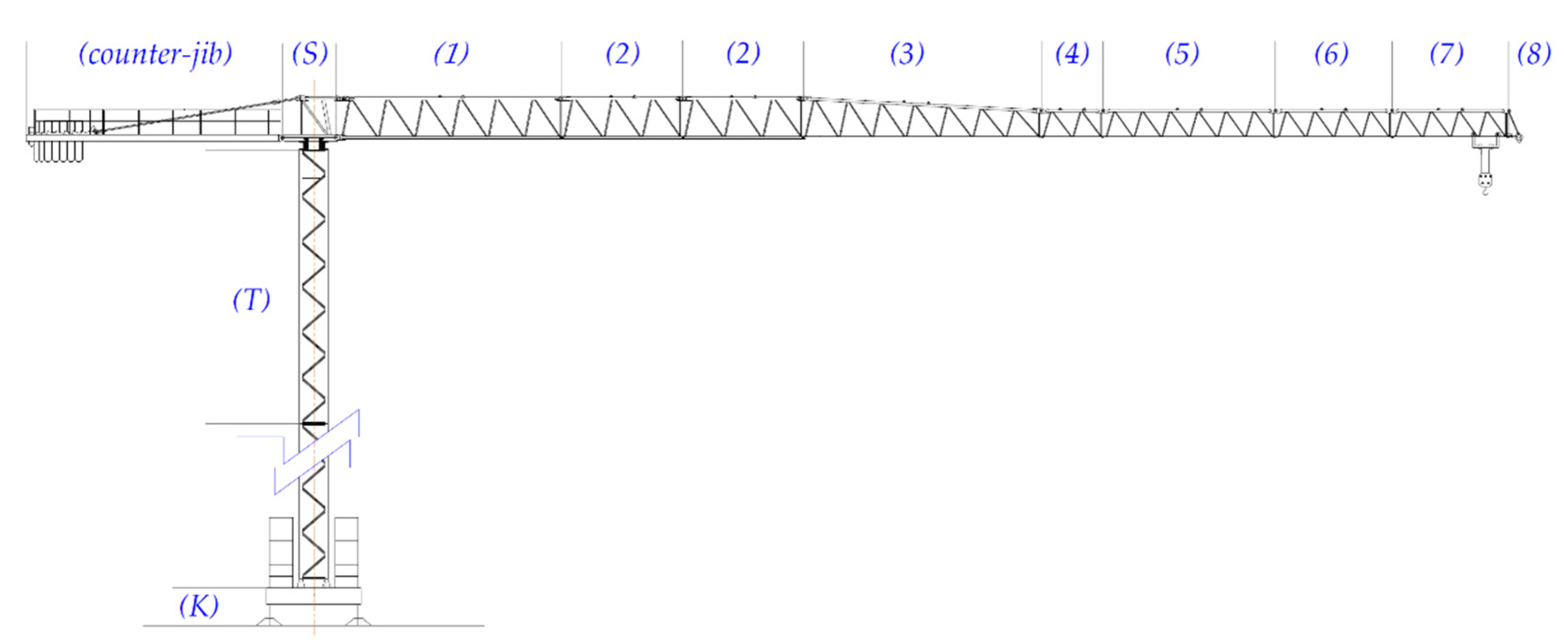
Figure 3.
Details of the simplified geometry of the top-slewing tower crane: (a) part of the crane jib with counterweight ballast, operator’s cabin, and jib; (b) base of the studied crane with central ballast; (c) truss structure of the jib; (d) truss structure of the tower.
Figure 3.
Details of the simplified geometry of the top-slewing tower crane: (a) part of the crane jib with counterweight ballast, operator’s cabin, and jib; (b) base of the studied crane with central ballast; (c) truss structure of the jib; (d) truss structure of the tower.
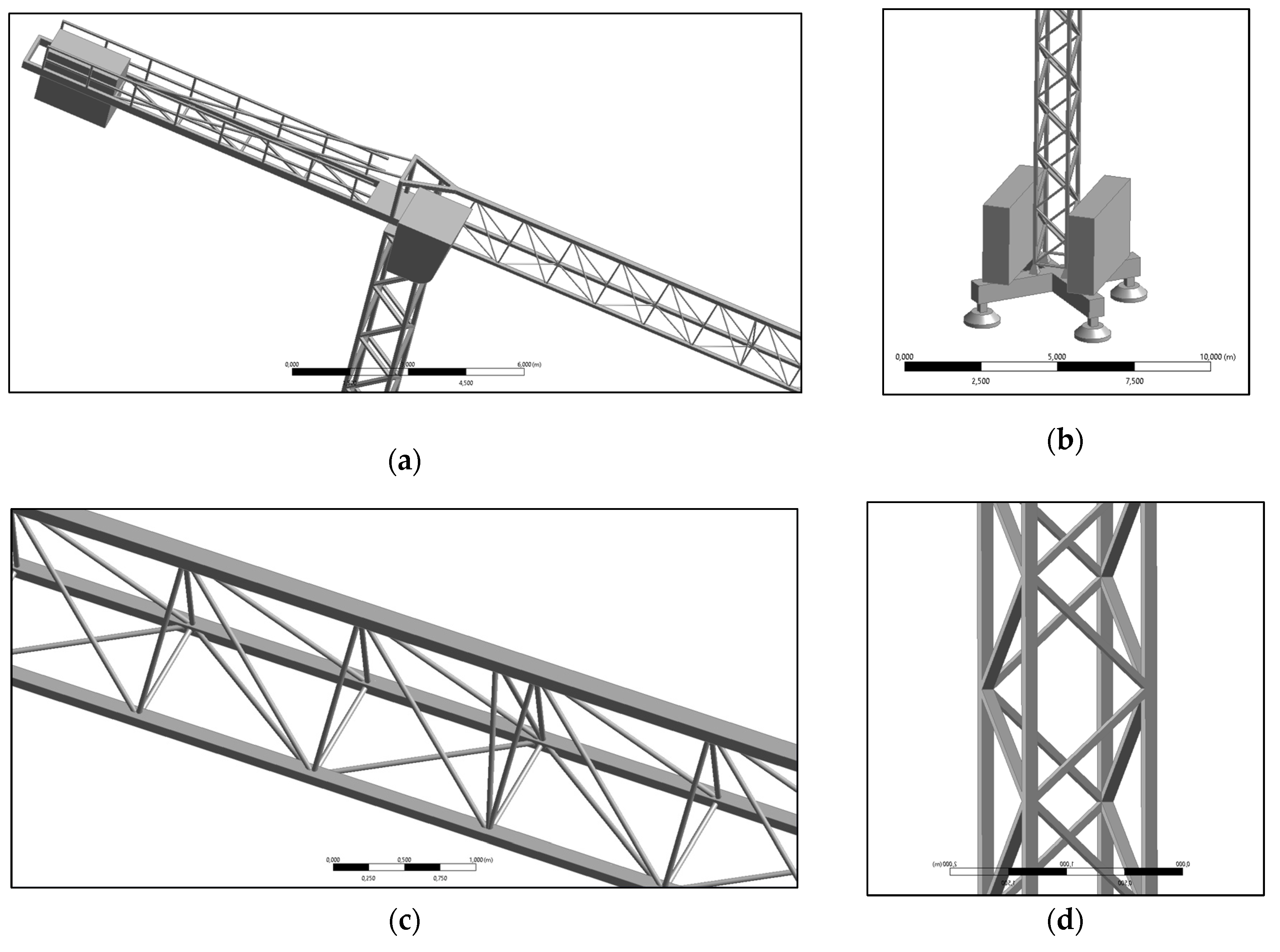
Figure 4.
Details of CFD simulations: (a) the studied crane inside the domain willed with air ; (b) the applied wind profiles.
Figure 4.
Details of CFD simulations: (a) the studied crane inside the domain willed with air ; (b) the applied wind profiles.
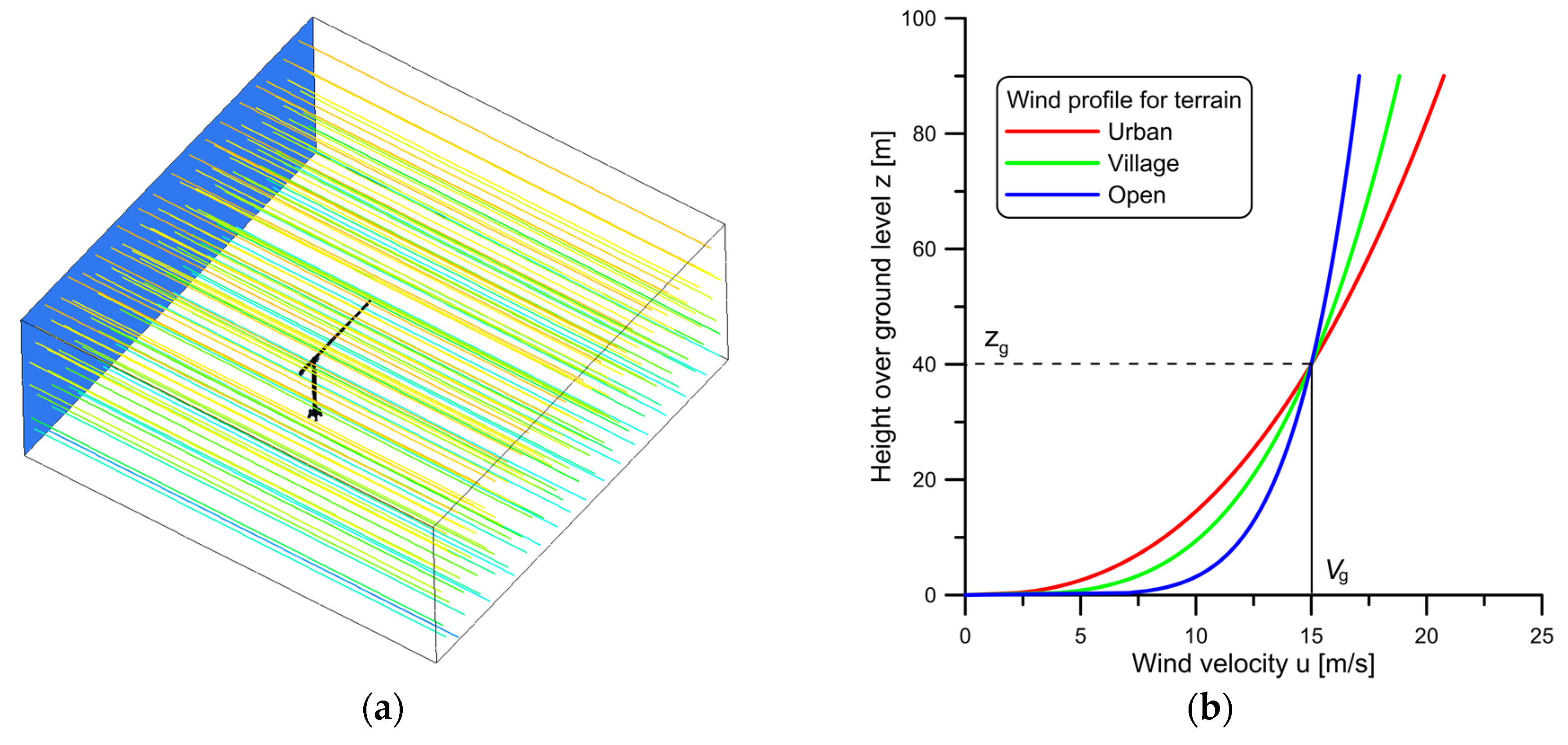
Figure 5.
Cane geometry configuration.
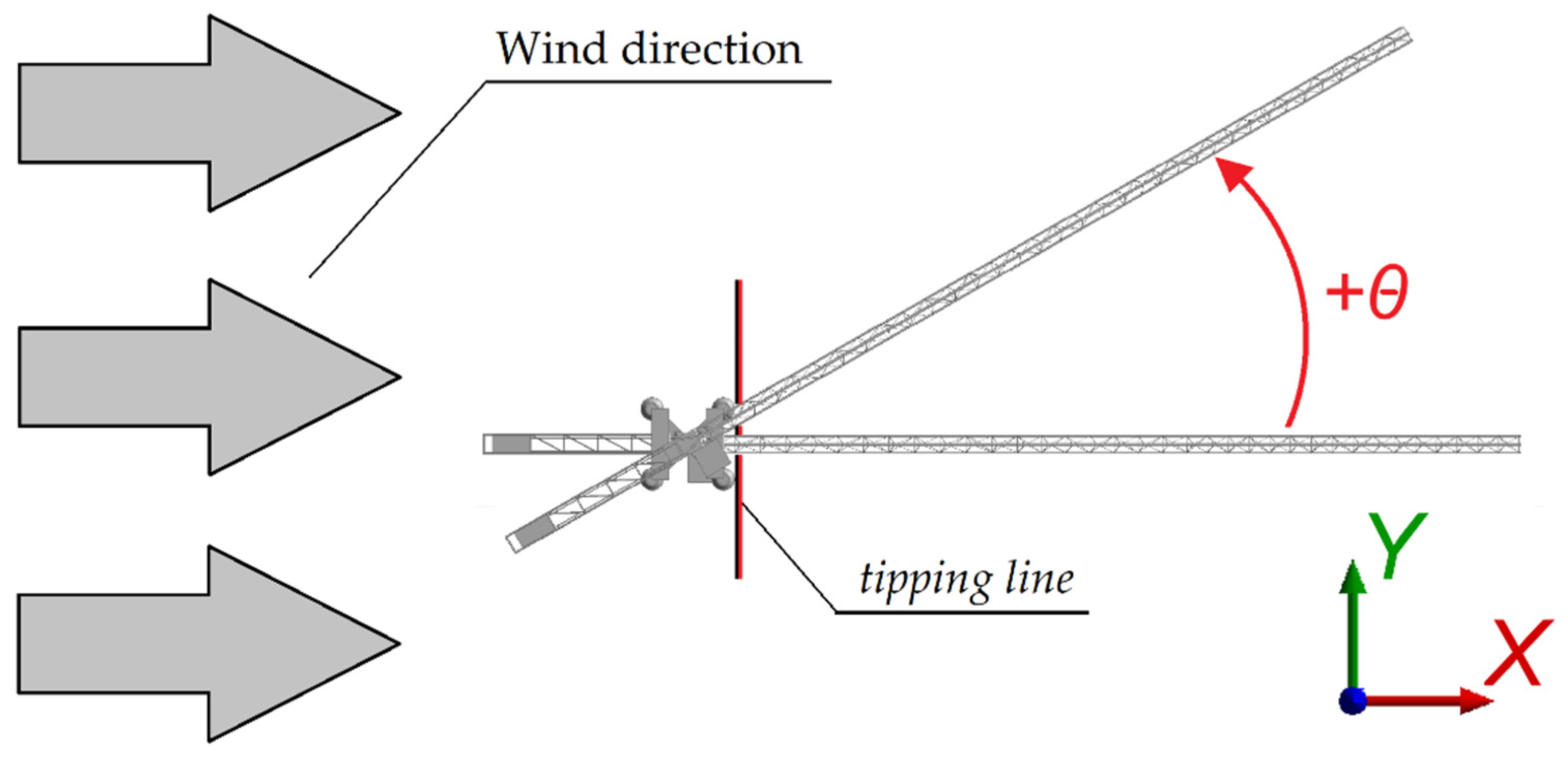
Figure 6.
Details of the automatically generated mesh: (a) part of the crane jib with operator’s cabin; (b) base of the studied crane with central ballast; (c) part of the truss structure of the jib; (d) part of the truss structure of the tower.
Figure 6.
Details of the automatically generated mesh: (a) part of the crane jib with operator’s cabin; (b) base of the studied crane with central ballast; (c) part of the truss structure of the jib; (d) part of the truss structure of the tower.
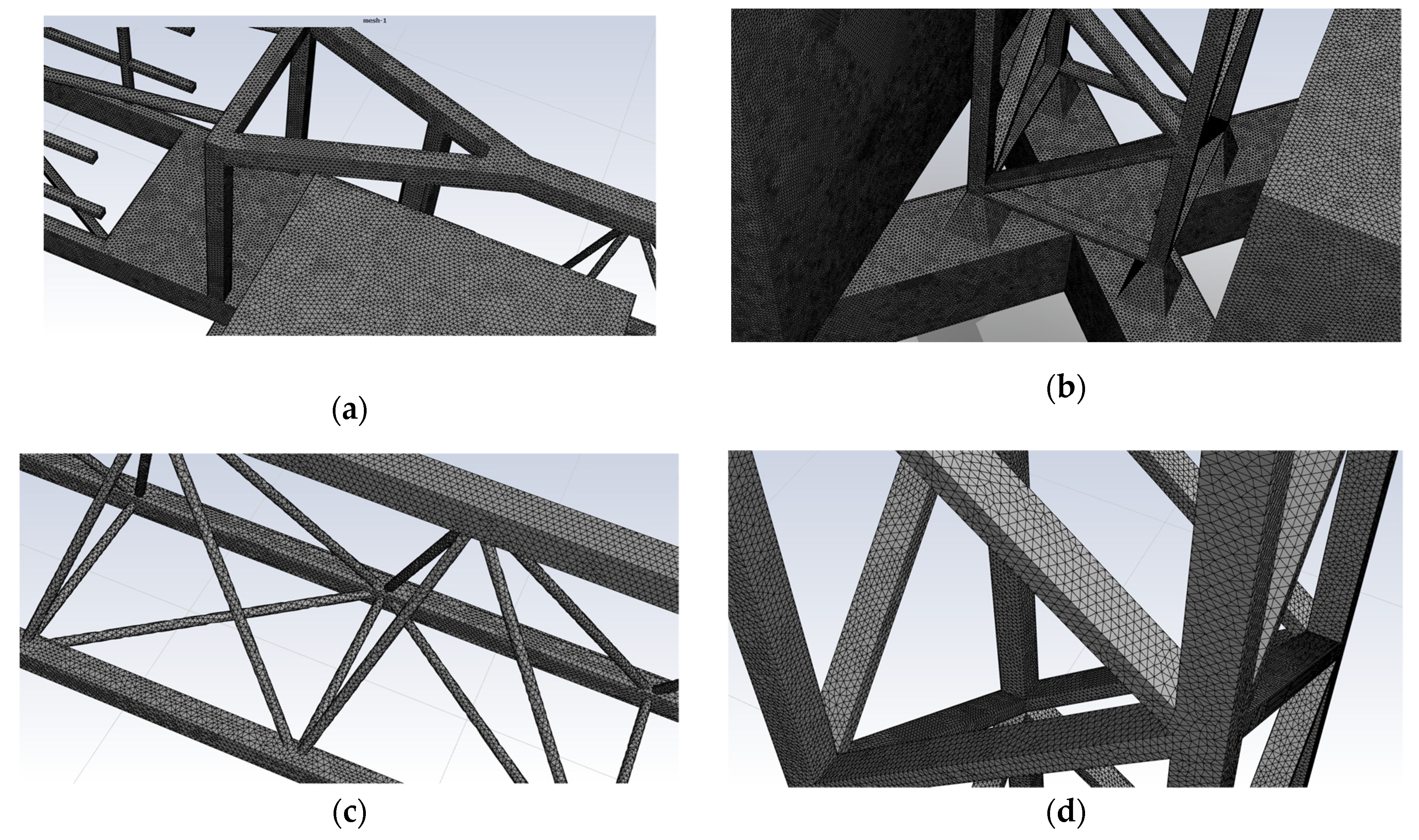
Figure 7.
Static pressure distribution (urban terrain, θ=90°).
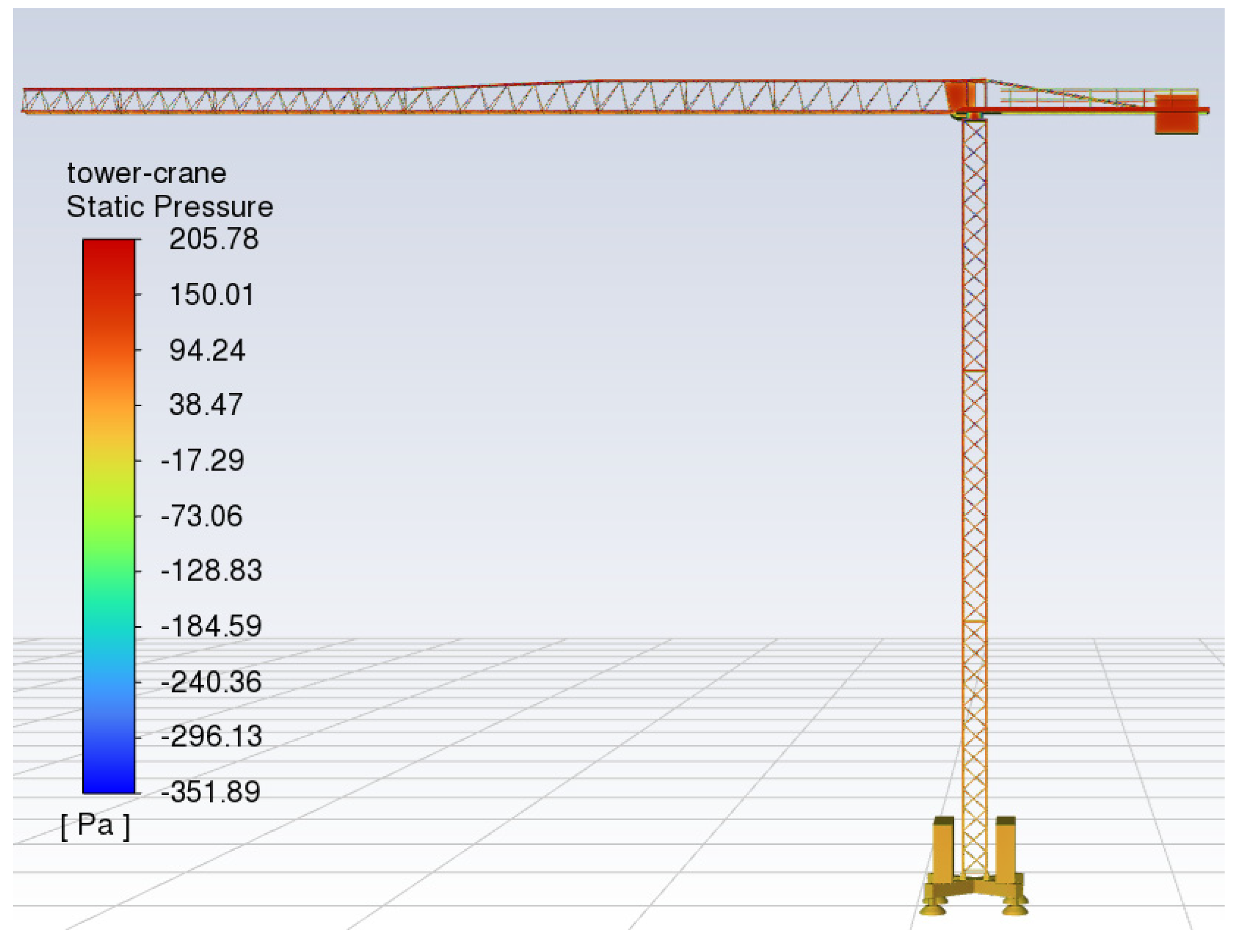
Figure 8.
Components of the aerodynamic forces induced by the wind as a function of angle θ for an urban, village, and open terrain (Vg = 15 m/s, zg = 40 m): (a) component Fx; (b) component Fy; (c) component Fz; (d) overturning moment Mtip.
Figure 8.
Components of the aerodynamic forces induced by the wind as a function of angle θ for an urban, village, and open terrain (Vg = 15 m/s, zg = 40 m): (a) component Fx; (b) component Fy; (c) component Fz; (d) overturning moment Mtip.
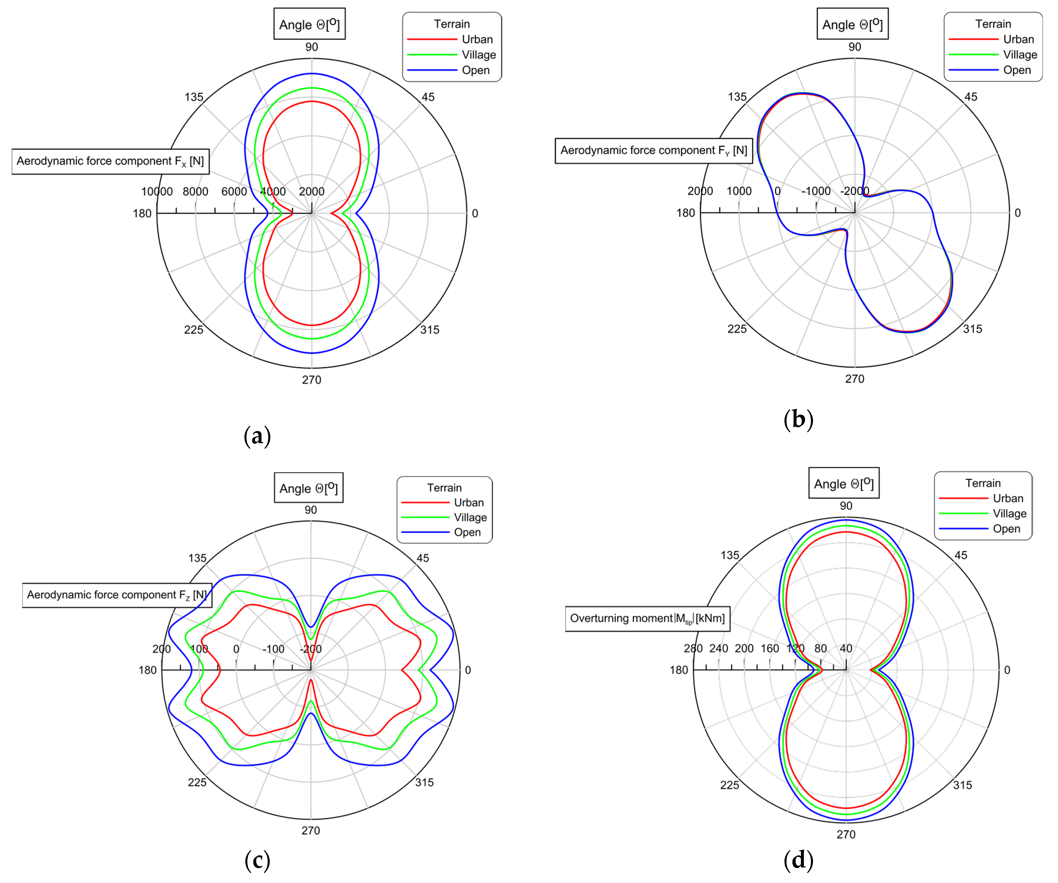
Figure 9.
Mass distribution diagram of the Liebherr 71 EC-B5, which is considered in the calculations according to Eurocode (Aref computed for θ = 90°).
Figure 9.
Mass distribution diagram of the Liebherr 71 EC-B5, which is considered in the calculations according to Eurocode (Aref computed for θ = 90°).
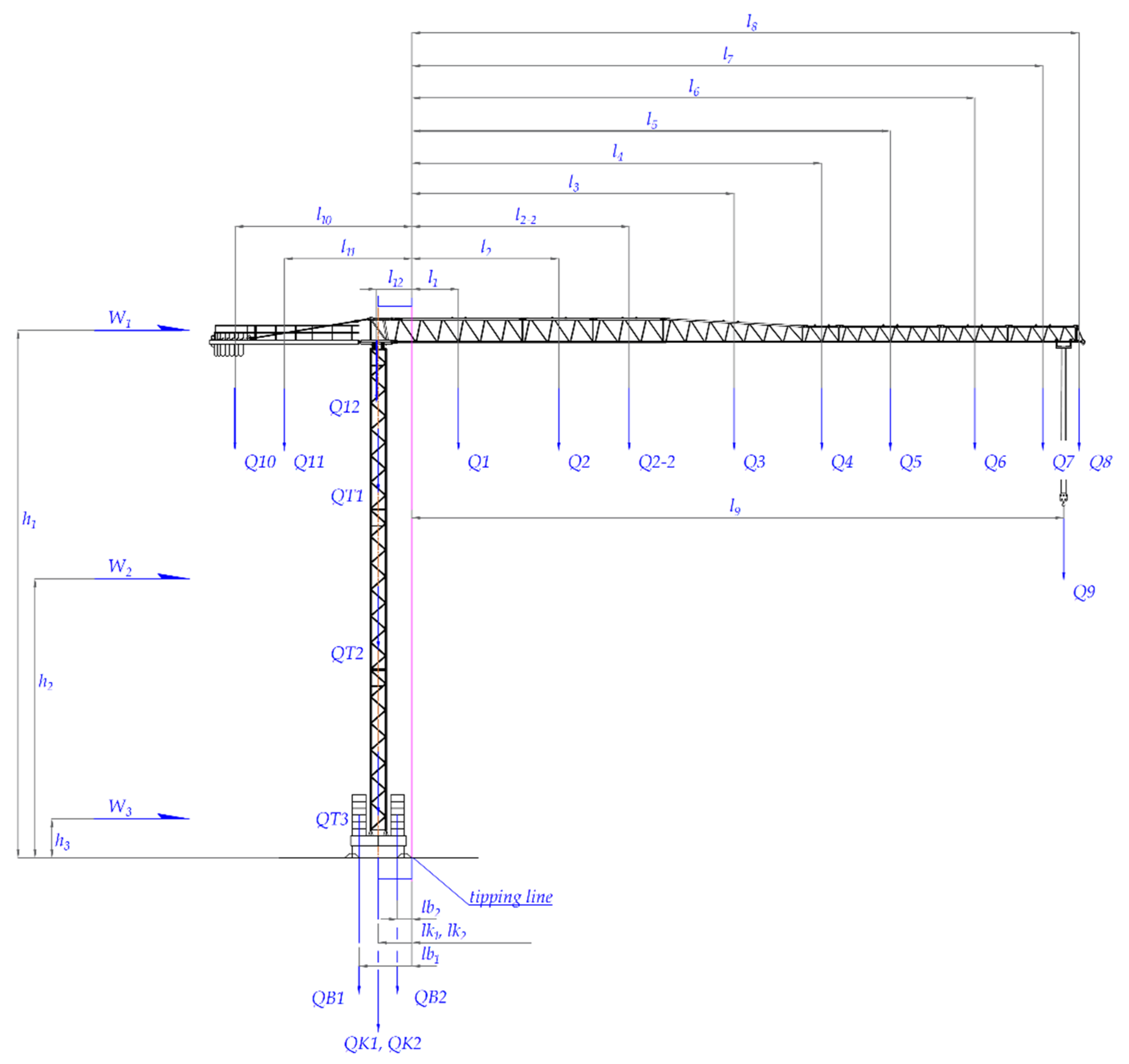
Figure 10.
Mass distribution of the tower crane Liebherr 71EC-B5 is considered in the calculations according to Eurocode (Aref determined for θ = 90°). It is the most adverse position of the jib against the tipping line (no payload assumed).
Figure 10.
Mass distribution of the tower crane Liebherr 71EC-B5 is considered in the calculations according to Eurocode (Aref determined for θ = 90°). It is the most adverse position of the jib against the tipping line (no payload assumed).
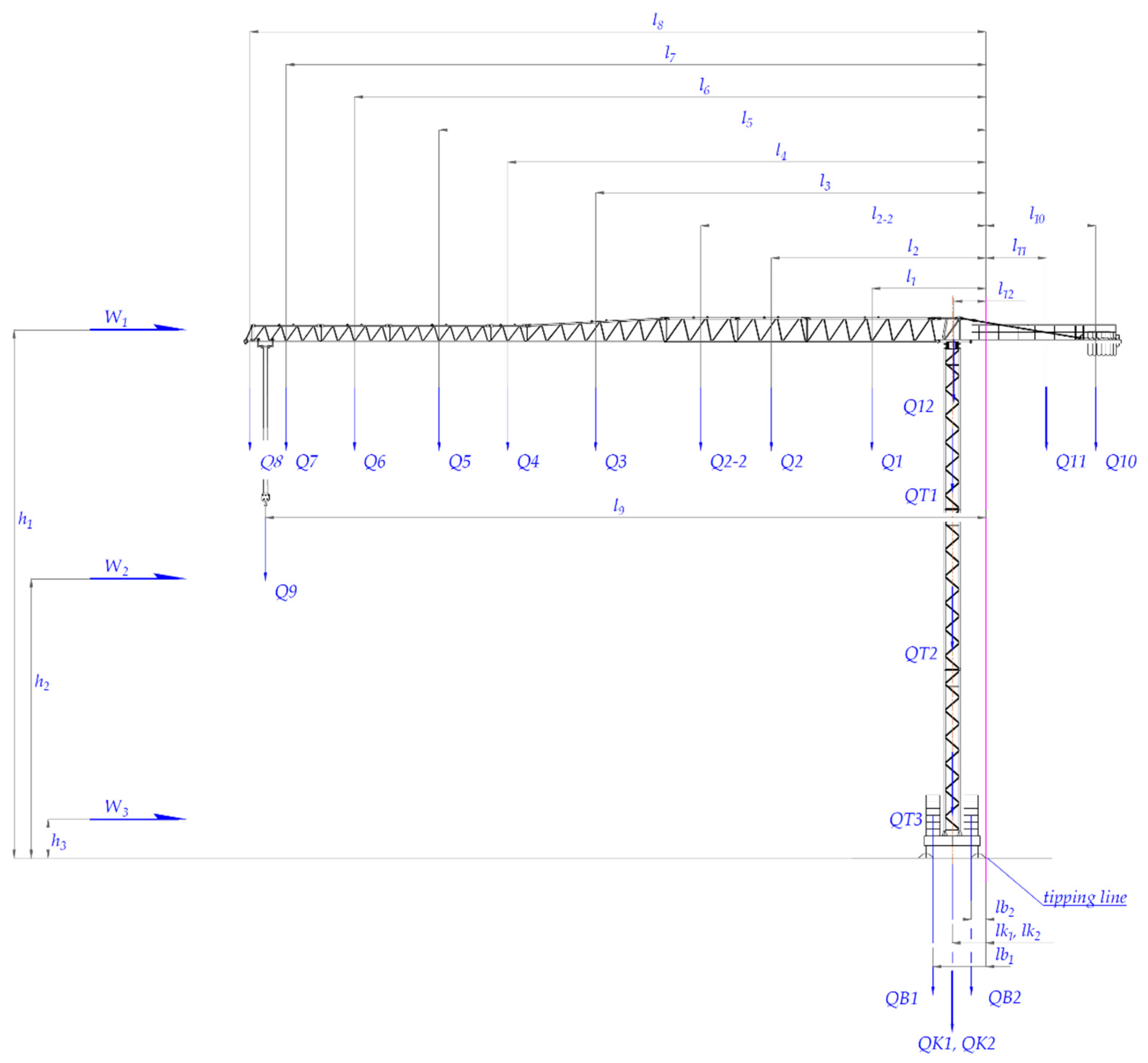
Figure 11.
The values of the overturning moment obtained from the values of forces based on the analytical approach (Eurocode) MO EuroCODE90° and the CFD results of MO CFD 71EC-B in case 2 without payload.
Figure 11.
The values of the overturning moment obtained from the values of forces based on the analytical approach (Eurocode) MO EuroCODE90° and the CFD results of MO CFD 71EC-B in case 2 without payload.
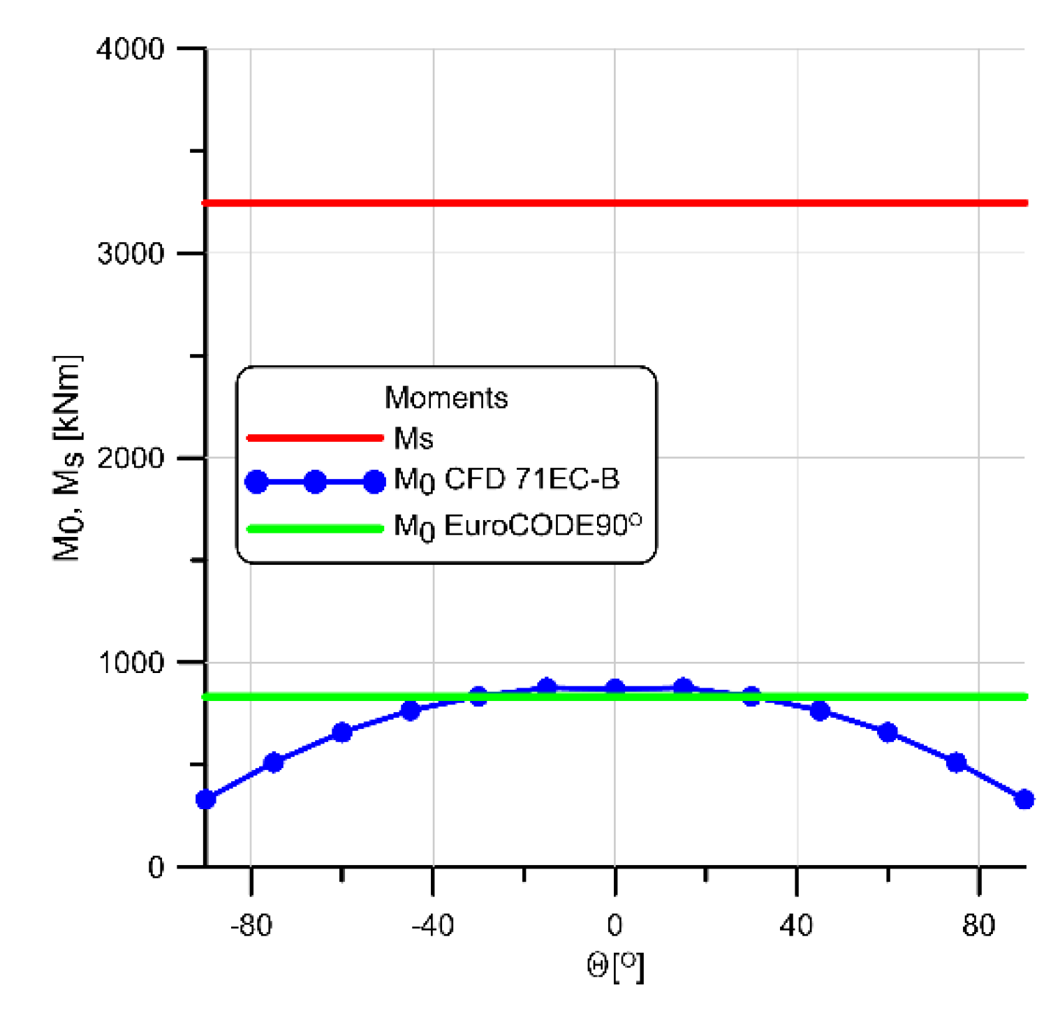
Figure 12.
Characteristics of the overturning moments according to CFD as a function of the jib rotation angle θ compared with stabilizing moment MS (EuroCODE) for selected wind speed: (a) Case 1 with maximum jib load; (b) Case 4 no load on the jib.
Figure 12.
Characteristics of the overturning moments according to CFD as a function of the jib rotation angle θ compared with stabilizing moment MS (EuroCODE) for selected wind speed: (a) Case 1 with maximum jib load; (b) Case 4 no load on the jib.
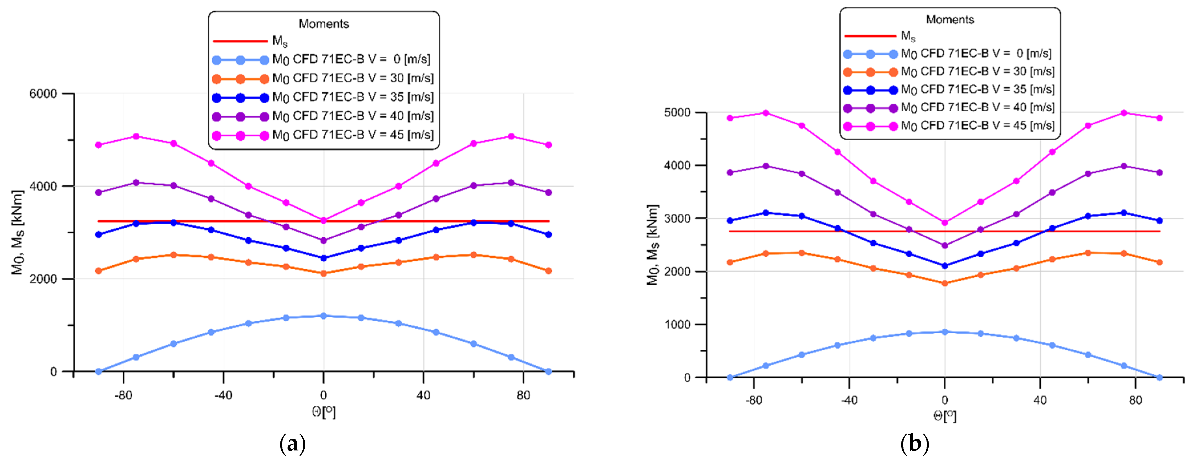
Figure 13.
Overturning moments obtained from CFD for chosen jib rotation angle θ = ±75°compared with the overturning and stabilizing moments according to EuroCODE: (a) Case 1 with maximum jib load; (b) Case 4 no load on the jib.
Figure 13.
Overturning moments obtained from CFD for chosen jib rotation angle θ = ±75°compared with the overturning and stabilizing moments according to EuroCODE: (a) Case 1 with maximum jib load; (b) Case 4 no load on the jib.
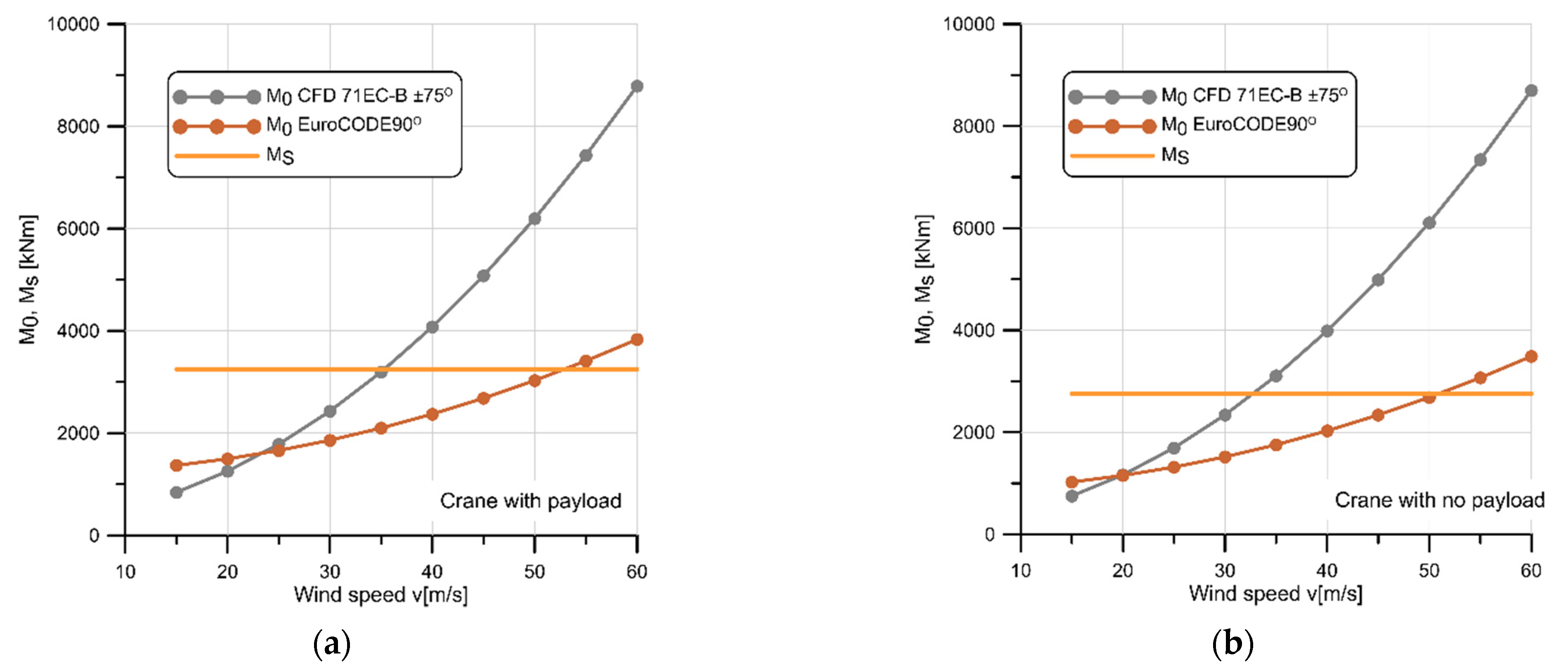
Figure 14.
Schema of the mass distribution for the tower crane Liebherr 71 EC-B5 determining overturning and stabilizing movements necessary to obtain the trace of the gravity center.
Figure 14.
Schema of the mass distribution for the tower crane Liebherr 71 EC-B5 determining overturning and stabilizing movements necessary to obtain the trace of the gravity center.
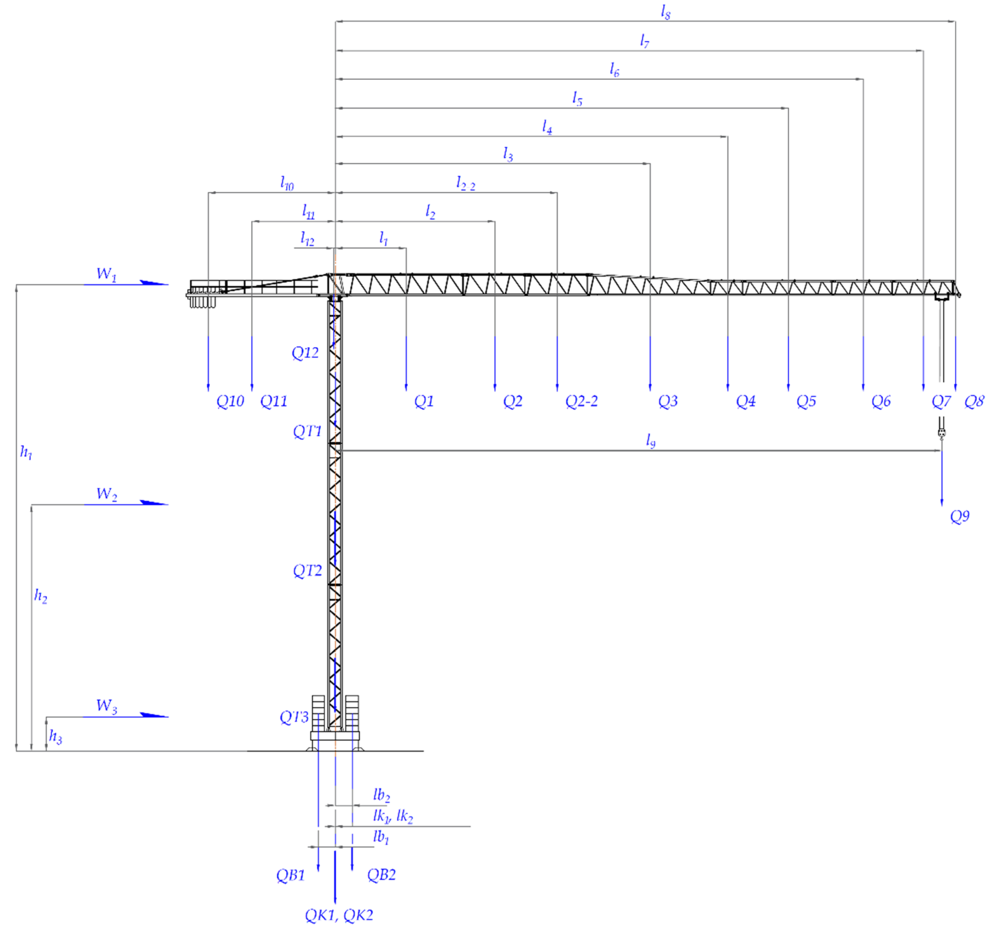
Figure 16.
Trace of the center of gravity where the wind direction was assumed to be from left to right. Numbers 1 to 4 are the tipping edges of the crane, considering the actual support spacing of 5 m (to the axis of the supports 3.8m) for the case: (a) Case 1, where there is a maximum load on the jib Q1 = 1000 kg at 50 m from the crane tower; (b) Case 4, where there is no load on the jib Q1 = 0 kg at 50 m from the crane tower.
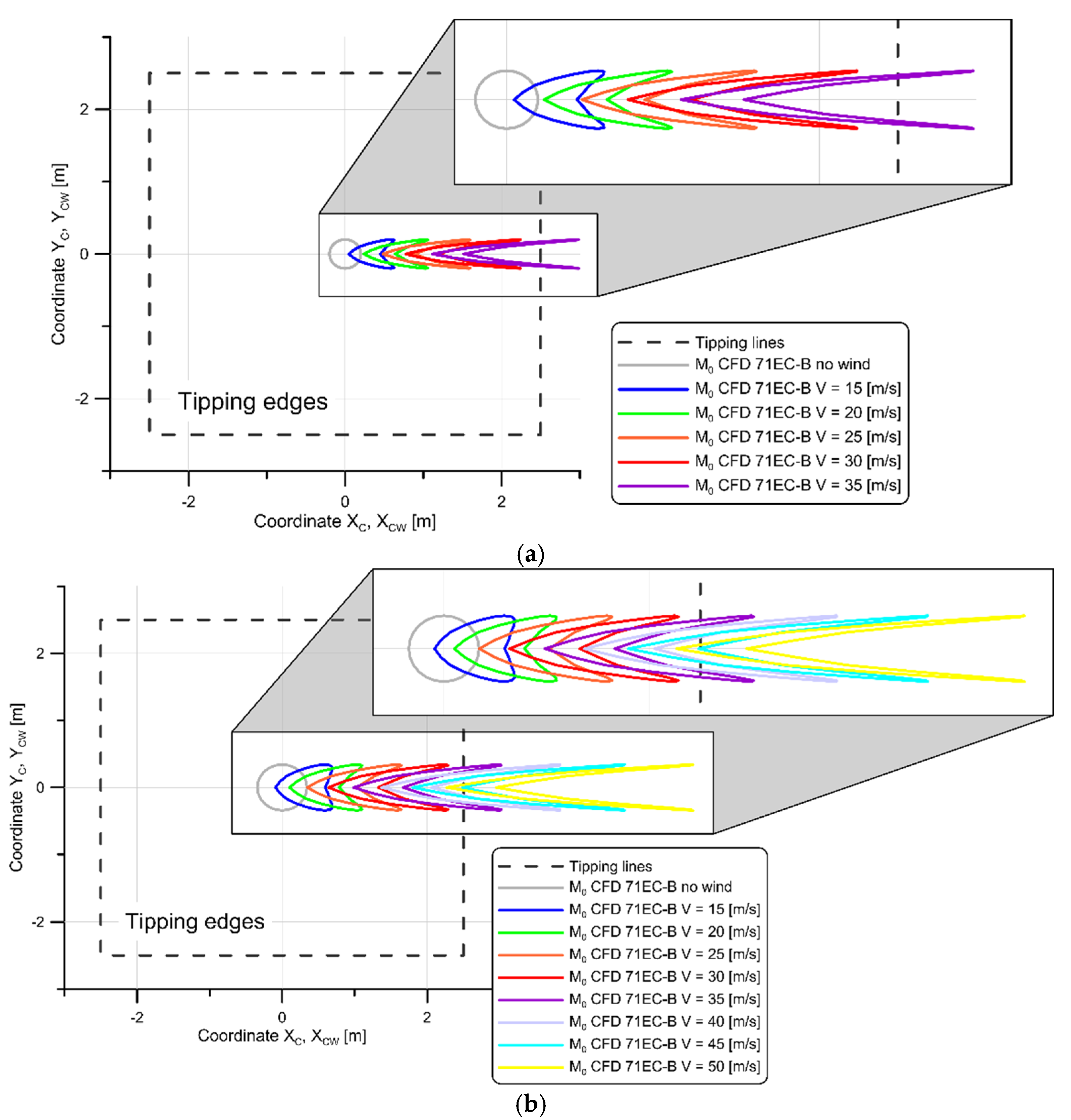

Table 1.
Results of the convergence test.
| le [m] | leMAX [m] | Nodes | Cells | Fx [N] | Mtip [Nm] | Cx | CM |
|---|---|---|---|---|---|---|---|
| 0.0150 | 4.0 | 13,097,189 | 73,925,163 | 7740.040 | 255,158.070 | 2.319 | 2.017 |
| 0.0175 | 4.5 | 9,979,287 | 56,384,955 | 7737.990 | 255,105.940 | 2.318 | 2.017 |
| 0.0200 | 5.0 | 7,959,409 | 44,895,413 | 7783.727 | 256,793.930 | 2.332 | 2.030 |
Table 2.
Aerodynamic drag force coefficients for open terrain, Vref = 12.924 m/s.
| Angle θ [°] | Cx | Cy | Cz | Ctip |
|---|---|---|---|---|
| 0 | 0.880 | 0.003 | 0.025 | 0.494 |
| 15 | 1.028 | -0.047 | 0.040 | 0.636 |
| 30 | 1.192 | -0.181 | 0.030 | 0.792 |
| 45 | 1.418 | -0.289 | 0.029 | 1.025 |
| 60 | 1.655 | -0.309 | 0.019 | 1.260 |
| 75 | 1.836 | -0.224 | 0.005 | 1.443 |
| 90 | 1.898 | -0.010 | -0.018 | 1.497 |
Aref = 48.27 m², Bref = 37.9 m, ρ = 1.225 kg/m3.
Table 3.
Aerodynamic drag force coefficients for village terrain, Vref = 11.716 m/s.
| Angle θ [°] | Cx | Cy | Cz | Ctip |
|---|---|---|---|---|
| 0 | 0.895 | 0.004 | 0.022 | 0.545 |
| 15 | 1.077 | -0.057 | 0.037 | 0.724 |
| 30 | 1.267 | -0.214 | 0.024 | 0.913 |
| 45 | 1.545 | -0.349 | 0.024 | 1.183 |
| 60 | 1.838 | -0.378 | 0.006 | 1.488 |
| 75 | 2.052 | -0.273 | -0.004 | 1.697 |
| 90 | 2.125 | -0.014 | -0.030 | 1.762 |
Aref = 48.27 m², Bref = 37.9 m, ρ = 1.225 kg/m3.
Table 4.
Aerodynamic drag force coefficients for urban terrain, Vref = 10.713 m/s.
| Angle θ [°] | Cx | Cy | Cz | Ctip |
|---|---|---|---|---|
| 0 | 0.898 | 0.005 | 0.013 | 0.613 |
| 15 | 1.109 | -0.069 | 0.031 | 0.810 |
| 30 | 1.325 | -0.253 | 0.016 | 1.028 |
| 45 | 1.654 | -0.406 | 0.013 | 1.361 |
| 60 | 1.996 | -0.443 | -0.004 | 1.697 |
| 75 | 2.247 | -0.319 | -0.018 | 1.951 |
| 90 | 2.332 | -0.015 | -0.052 | 2.030 |
Aref = 48.27 m², Bref = 37.9 m, ρ = 1.225 kg/m3.
Table 5.
The values of masses – overturning moments, variant 1.
| Jib | Load | |||||||||
|---|---|---|---|---|---|---|---|---|---|---|
| Mass | ||||||||||
| Q1 | Q2 | Q2-2 | Q3 | Q4 | Q5 | Q6 | Q7 | Q8 | Q9 | |
| 1820 | 530 | 530 | 740 | 160 | 380 | 200 | 170 | 60 | 1000 | [kg] |
| 17,854 | 5199 | 5199 | 7259 | 1570 | 3728 | 1962 | 1668 | 589 | 9810 | [N] |
| Distance from the tipping line. | ||||||||||
| l1 | l2 | l2-2 | l3 | l4 | l5 | l6 | l7 | l8 | l9 | |
| 3.41 | 10.72 | 15.86 | 23.51 | 29.91 | 34.90 | 41.07 | 46.04 | 48.68 | 48.00 | [m] |
| Moments | ||||||||||
| M1 | M2 | M2-2 | M3 | M4 | M5 | M6 | M7 | M8 | M9 | |
| 60,795 | 55,724 | 82,474 | 170,686 | 46,947 | 130,119 | 80,571 | 76,775 | 28,650 | 470,880 | [Nm] |
where: Q1 – mass of the 1th part (1), Q2 – mass of the 2nd part (2), Q2-2 – mass of the 3rd part (2), Q3 – mass of the 4th part (3), Q4 – mass of the 5th part (4), Q5 – mass of the 6th part (5), Q6 – mass of the 7th part (6), Q7 – mass of the 8th part (7), Q8 – mass of the 9th part (8), Q9 – mass of the payload at the end of the jib.
Table 6.
The values of the masses – stabilizing moments, variant 1.
| Counter-jib, counterweight, slewing platform | Tower | Central ballast | Cruciform base | |||||||
|---|---|---|---|---|---|---|---|---|---|---|
| Mass | ||||||||||
| Q10 | Q11 | Q12 | QT1 | QT2 | QT3 | QB1 | QB2 | QK1 | QK2 | |
| 9750 | 2190 | 3310 | 2450 | 2450 | 3320 | 30,000 | 30,000 | 1950 | 1730 | [kg] |
| 95,648 | 21,484 | 32,471 | 24,035 | 24,035 | 32,569 | 294,300 | 294,300 | 19,130 | 16,971 | [N] |
| Distance from the tipping line | ||||||||||
| l10 | l11 | l12 | lt1 | lt2 | lt3 | lb1 | lb2 | lk1 | lk2 | |
| 12.91 | 9.30 | 2.57 | 2.45 | 2.45 | 2.45 | 3.85 | 1.05 | 2.45 | 2.45 | [m] |
| Moments | ||||||||||
| Ml10 | Ml11 | Ml12 | Mt1 | Mt2 | Mt3 | Mb1 | Mb2 | Mk1 | Mk2 | |
| 1,234,338 | 199,850 | 83,372 | 58,885 | 58,885 | 79,795 | 1,133,055 | 309,015 | 46,867 | 41,580 | [Nm] |
where: Q10 – counterweight mass, Q11 – counterweight jib mass, Q12 – turntable device mass, QT1 – mass of the 1st part of the tower, QT2 - mass of the 2nd part of the tower, QT3 - mass of the 3rd part of the tower with turntable, QB4 – mass of the right lower ballast, QB5 - mass of the left lower ballast, QK5 – mass of the 1st part of the base cruciform, QK7 – mass of the 2nd part of the base cruciform.
Table 7.
The values of masses of Variant 2 – stabilizing moments.
| Jib | Load | |||||||||
|---|---|---|---|---|---|---|---|---|---|---|
| Mass | ||||||||||
| Q1 | Q2 | Q2-2 | Q3 | Q4 | Q5 | Q6 | Q7 | Q8 | Q9 | |
| 1820 | 530 | 530 | 740 | 160 | 380 | 200 | 170 | 60 | 1000 | [kg] |
| 17854 | 5199 | 5199 | 7259 | 1570 | 3728 | 1962 | 1668 | 589 | 9810 | [N] |
| Distance from the tipping line. | ||||||||||
| l1 | l2 | l2-2 | l3 | l4 | l5 | l6 | l7 | l8 | l9 | |
| 8.30 | 15.61 | 20.76 | 28.41 | 34.80 | 39.80 | 45.96 | 50.93 | 53.57 | 52.44 | [m] |
| Moments | ||||||||||
| M1 | M2 | M2-2 | M3 | M4 | M5 | M6 | M7 | M8 | M9 | |
| 148157 | 81164 | 107914 | 206207 | 54627 | 148359 | 90171 | 84935 | 31530 | 514467 | [Nm] |
Table 8.
The values of the masses of Variant 2 – stabilizing moments and overturning moments (bold values) from counter-jib, counterweight only.
Table 8.
The values of the masses of Variant 2 – stabilizing moments and overturning moments (bold values) from counter-jib, counterweight only.
| Counter-jib, counterweight, slewing platform | Tower | Central ballast | Cruciform base | |||||||
|---|---|---|---|---|---|---|---|---|---|---|
| Mass | ||||||||||
| Q10 | Q11 | Q12 | QT1 | QT2 | QT3 | QB1 | QB2 | QK1 | QK2 | |
| 9750 | 2190 | 3310 | 2450 | 2450 | 3320 | 30,000 | 30,000 | 1950 | 1730 | [kg] |
| 95,648 | 21,484 | 32,471 | 24,035 | 24,035 | 32,569 | 294,300 | 294,300 | 19,130 | 16,971 | [N] |
| Distance from the tipping line | ||||||||||
| l10 | l11 | l12 | lt1 | lt2 | lt3 | lb1 | lb2 | lk1 | lk2 | |
| 12,91 | 9,30 | 2,57 | 2,45 | 2,45 | 2,45 | 3,85 | 1,05 | 2,45 | 2,45 | [m] |
| Moments | ||||||||||
| Ml10 | Ml11 | Ml12 | Mt1 | Mt2 | Mt3 | Mb1 | Mb2 | Mk1 | Mk2 | |
| 1,234,338 | 199,850 | 83,372 | 58,885 | 58,885 | 79,795 | 1,133,055 | 309,015 | 46,867 | 41,580 | [Nm] |
Table 9.
Sums of the stabilizing and overturning moments for variants 1 and 2.
| Case | Stabilizing moments Σ MS | Overturning moments Σ MO | Σ MS - Σ MO |
|---|---|---|---|
| 1 | 3,245,465 | 1,203,620 | 2,041,845 |
| 2 | 3,245,465 | 732,740 | 2,512,725 |
| 3 | 3,270,948 | 861,055 | 2,409,893 |
| 4 | 2,756,482 | 861,055 | 1,895,427 |
Table 10.
The maximum wind speed V for which overturning moments cause loss of stability of the 71 EC-B crane.
Table 10.
The maximum wind speed V for which overturning moments cause loss of stability of the 71 EC-B crane.
| V[m/s] | Case 1 [kNm] | V[m/s] | Case 4 [kNm] | |||
|---|---|---|---|---|---|---|
| h1 = 38.46 m | MO EuroCODE 90° | MO CFD 75EC-B +/−75° | h1 = 38.46 m | MO EuroCODE 90° | MO CFD 75EC-B +/−75° | |
| 35.31 | - | 3247.02 | 32.81 | - | 2757.34 | |
| 52.89 | 3245.61 | - | 50.97 | 2756.78 | - | |
Table 11.
The values of masses for overturning moments.
| Jib | Load | |||||||||
|---|---|---|---|---|---|---|---|---|---|---|
| Mass | ||||||||||
| Q1 | Q2 | Q2-2 | Q3 | Q4 | Q5 | Q6 | Q7 | Q8 | Q9 | |
| 1820 | 530 | 530 | 740 | 160 | 380 | 200 | 170 | 60 | 1000 | [kg] |
| 17,854 | 5199 | 5199 | 7259 | 1570 | 3728 | 1962 | 1668 | 589 | 9810 | [N] |
| Distance from the crane axis | ||||||||||
| l1 | l2 | l2-2 | l3 | l4 | l5 | l6 | l7 | l8 | l9 | |
| 5.86 | 13.17 | 18.31 | 25.96 | 32.36 | 37.35 | 43.52 | 48.49 | 51.13 | 50,00 | [m] |
| Moments | ||||||||||
| M1 | M2 | M2-2 | M3 | M4 | M5 | M6 | M7 | M8 | M9 | |
| 104,538 | 68,462 | 95,212 | 188,472 | 50,792 | 139,252 | 85,378 | 80,861 | 30,092 | 490,487 | [Nm] |
Description as in the case of Table 5.
Table 12.
The values of masses for stabilizing moments.
| Counter-jib, counterweight | Tower, slewing platform | Central ballast | Cruciform base | |||||||
|---|---|---|---|---|---|---|---|---|---|---|
| Mass | ||||||||||
| Q10 | Q11 | Q12 | QT1 | QT2 | QT3 | QB1 | QB2 | QK1 | QK2 | |
| 9750 | 2190 | 3310 | 2450 | 2450 | 3320 | 30,000 | 30,000 | 1950 | 1730 | [kg] |
| 95,648 | 21,484 | 32,471 | 24,035 | 24,035 | 32,569 | 294,300 | 294,300 | 191,30 | 16,971 | [N] |
| Distance from the crane axis | ||||||||||
| l10 | l11 | l12 | lt1 | lt2 | lt3 | lb1 | lb2 | lk1 | lk2 | |
| 10.46 | 6.85 | 0.12 | 0.001 | 0.001 | 0.001 | 1.40 | 1.40 | 0.001 | 0.001 | [m] |
| Moments | ||||||||||
| Ml10 | Ml11 | Ml12 | Mt1 | Mt2 | Mt3 | Mb1 | Mb2 | Mk1 | Mk2 | |
| 1,000,001 | 147,214 | 3818 | 24.0 | 24.0 | 32.6 | 411,346 | 411,346 | 19.1 | 17.0 | [Nm] |
Description as in the case of Table 6.
Disclaimer/Publisher’s Note: The statements, opinions and data contained in all publications are solely those of the individual author(s) and contributor(s) and not of MDPI and/or the editor(s). MDPI and/or the editor(s) disclaim responsibility for any injury to people or property resulting from any ideas, methods, instructions or products referred to in the content. |
© 2025 by the authors. Licensee MDPI, Basel, Switzerland. This article is an open access article distributed under the terms and conditions of the Creative Commons Attribution (CC BY) license (http://creativecommons.org/licenses/by/4.0/).
Copyright: This open access article is published under a Creative Commons CC BY 4.0 license, which permit the free download, distribution, and reuse, provided that the author and preprint are cited in any reuse.


