
Submitted:
31 March 2025
Posted:
01 April 2025
You are already at the latest version
Abstract
This study investigates the relationship between the compressive strength results of two-course molded masonry specimens and three-course masonry specimens extracted from previously constructed masonry, aiming to analyze the reliability of extrapolating laboratory-obtained values to field situations. To achieve this, compression tests were performed on individual hollow clay bricks, laboratory-molded masonry specimens, and masonry specimens extracted from constructed masonry walls, following the prescriptions of NBR 15270-2 [4] and NBR 16868-3 [6]. The results demonstrate that three-course masonry specimens extracted from completed masonry wall exhibit lower characteristic compressive strength compared to two-course molded masonry specimens, highlighting the influence of the height/thickness ratio, construction conditions, and mortar joint continuity between courses on the final strength of the masonry. Additionally, a greater dispersion in the results of extracted masonry specimens was observed, indicating that execution-related factors, such as variations in mortar joint thickness and heterogeneity in the laying process, impact the variability of the tests. The findings of this study may contribute to the evolution of normative criteria and to improving the interpretation of retest results in masonry structures.
Keywords:
masonry structures
; compressive strength
; masonry specimens
1. Theoretical Background
Structural masonry is one of the oldest and most widespread construction systems globally, employed in various regions and construction contexts. The interaction between units (bricks) and mortar, whose physical and mechanical properties can vary significantly, directly influences the structural performance of masonry elements. Given this complexity, structural masonry design requires an in-depth analysis of the unit/mortar composite behavior, considering their interactions and synergistic effects [14].
1.1. Mechanical Properties of Masonry Structures
Compressive strength is the main mechanical property used to evaluate the quality of masonry and constitutes the most relevant parameter in the structural design of these buildings. Similar to concrete, the 28-day compressive strength is widely adopted as a reference in normative codes worldwide, determined through standardized masonry specimen tests. These masonry specimens, to ensure a faithful representation of masonry's structural behavior, must be composed of multiple courses of units interspersed with mortar layers, using materials identical to those used in the construction of the structural element under study, such as units (bricks), mortar, and grout [25].
The performance of structural masonry elements depends on the characteristics of all its constituent materials, namely, units and mortar, in the case of hollow masonry specimens [34]. In design, the specification of units must consider not only their compressive strength but also their compatibility with the mortar, as the interaction between these elements is decisive for the structural performance of the assembly [38]. While masonry units play a primary role in absorbing compressive loads, mortar ensures load transmission between units, provides adhesion to the assembly, and accommodates deformations, ensuring the structural integrity of the masonry [33,36].
The mechanical performance of masonry specimens subjected to compression is directly influenced by failure mechanisms, which are intrinsically related to the mechanical properties of the constituent materials. However, several additional factors also impact their structural behavior, including the strength ratio between components, preparation and testing conditions, mortar bedding arrangement, curing procedures, load application rate, and geometric characteristics of the units [22,29,33].
The masonry specimen failure can be ductile or brittle, depending on the mechanical characteristics of the mortar relative to the units [34]. The widely accepted mechanism in the technical community [33] postulates that masonry specimen failure will occur due to horizontal tension near the joint when the mortar's compressive strength is lower than that of the unit, and due to unit crushing when the unit’s compressive strength is lower than that of the mortar.
In this context, masonry failure under compression can occur in three typical forms, depending on the relationship between the mortar's compressive strength and the unit’s compressive strength [19].
(a) When the mortar strength is significantly lower than that of the unit, the overall masonry strength is conditioned by the mortar's load-bearing capacity, which tends to fail prematurely by crushing;
(b) When the mortar exhibits moderate strength relative to the unit, masonry strength is governed by the interaction between the unit’s compressive and tensile strengths, usually resulting in failure by lateral cracking due to transverse tension;
(c) When the mortar strength exceeds that of the unit, masonry strength is limited by the unit’s compressive strength, making the unit the critical element for the structural collapse of the assembly.
Additionally, the structural behavior of masonry units and bedding mortar differs significantly from that observed in uniaxial compression tests of isolated specimens. This discrepancy arises from the fact that the mechanical response of each individual component is not exclusively determined by its intrinsic properties but rather by the triaxial behavior resulting from the complex interaction between masonry elements.
1.2. Quality Control
Structural masonry is defined as a construction system in which masonry comprises the load-bearing structure of the building. In the context of evaluating the mechanical performance of this system, masonry specimens are simplified test specimens widely used in quality control, ensuring that project execution complies with the designer's specifications [33]. These experimental elements enable the determination of masonry's compressive strength, being essential for verifying whether structural parameters meet normative requirements and design guidelines.
Masonry specimens have been widely used in academic research and quality control of masonry structures, as they constitute simplified experimental models that are easy to construct and test, allowing for the assessment of masonry's mechanical behavior under controlled conditions. These test specimens offer operational and economic advantages, in addition to representing the interaction between different masonry system components [1,31]. In this context, standardization of two-unit masonry specimens is crucial from a practical standpoint for quality control in construction execution [33].
For specification in design, prior characterization of materials to be used is strongly recommended, avoiding unexpected interactions between these materials that could lead to different results. Furthermore, considering the importance and usefulness of a reference source for project specification, NBR 16868-1 [5] provides a table with suggested values for combinations of units and mortars, based on their mechanical properties.

Table 1.
Recommendation for design specifications with solid-web hollow clay units.
| fbk | fa | fgk | fpk/fbk | fpk*/fbk | fpk | fpk* |
| (MPa) | (MPa) | |||||
| 10,0 | 8,0 | 20,0 | 0,60 | 1,60 | 6,0 | 9,6 |
| 14,0 | 12,0 | 25,0 | 0,60 | 1,60 | 8,4 | 13,4 |
| 18,0 | 15,0 | 30, | 0,60 | 1,60 | 10,8 | 17,3 |
Adapted by the authors from NBR 16868-1 [5].
For the determination of the characteristic compressive strength of masonry, the Eurocode 6 standard [17] establishes equations based on the compressive strength of the unit, the mean compressive strength of the mortar, and the mortar joint thickness. The equation includes the factor K, a constant that depends on the type of unit and mortar used, and is applied in situations where experimental results are not available.
fk= K x fb^(0.7) x fm^(0.3)
Additionally, the European standard provides for the execution of experimental tests through EN 1052 [18].
For construction execution control purposes, the Brazilian standard NBR 16868-2 [5] regulates the characterization tests for masonry strength, covering its main structural components, such as masonry specimens, units, mortars, and grouts. This standard prescribes that the characteristic compressive strength obtained experimentally must be at least equivalent to the value defined in the design. Thus, destructive tests on masonry specimens, combined with rigorous technological control procedures, are essential to ensure structural safety and the proper performance of buildings [31].
At the international level, the need for technological control is also widely recognized, as exemplified by the American standard TMS 602 [40], the Australian standard AS 3700 [9], the European standard Eurocode 6 [17], and the Canadian standard CSA S304 [11]. These guidelines establish technical criteria for evaluating the mechanical strength of structural masonry, contributing to the standardization of testing procedures and the reliability of experimental results. Additionally, the test specimens represented by masonry specimens are standardized, as illustrated by the Figure 1.
Some international standards, such as TMS 602 [40] and CSA S304 [11], present limitations as they do not include compressive strength values for masonry specimens constructed with high-strength units. Studies conducted by Fortes et al. [19] analyzed masonry specimens composed of concrete units with strengths ranging from 21,6 MPa to 74,7 MPa (net area), combined with mortar and grout of varying strength. The tests were performed on ungrouted and grouted masonry specimens, allowing for the establishment of correlations between the strength of the units and the masonry specimens, with variations between 6 MPa and 70 MPa (net area) and between 3 MPa and 35 MPa (gross area).
In cases where a retest is required, Annex B of NBR 16868-3 [6] prescribes the procedure for extracting core specimens from executed masonry, with these specimens consisting of either masonry specimens or individual units. However, the standard does not provide correction factors or other guidelines for interpreting the results in a way that allows comparison between the obtained values and those specified in the design, which are determined through the testing of two-unit molded masonry specimens.
1.3. Variables That Influence the Compressive Strength of Masonry Elements
The structural performance of masonry elements depends on factors such as execution quality, environmental conditions, material properties, and unit geometry [31]. Examples include the individual strength of the mortar and units, the relationship between these strengths, the ratio between the unit height and its smallest horizontal dimension, the orientation of the units relative to the load application direction, and the mortar joint thickness. The interaction between these elements is crucial for the load-bearing capacity of the system, directly impacting the overall safety and performance of the structure [19,23,37].
For units with the same material composition and identical geometry, an increase in the compressive strength of the unit generally tends to result in an increase in the compressive strength of the masonry. This phenomenon occurs because the higher compressive strength of the unit enhances its transverse tensile strength, directly contributing to the overall load-bearing capacity of the wall [35]. However, this increase in unit strength does not necessarily lead to a proportional increase in the overall strength of the masonry [26].
When dealing with uniaxial compressive forces, NBR 16868-1 [5] states that the masonry strength (fk) should be determined based on wall tests, as specified in part 3 of the standard. However, it can also be estimated when using units with a height of 190 mm. In such cases, the characteristic compressive strength of masonry can be considered as 70% of the characteristic compressive strength of the masonry specimen (fpk), where the specimen consists of two units molded according to the specifications in this part of the standard, or 85% of the small wall (fppk), an element that must have a minimum height equivalent to five times the unit thickness.
Regarding the dimensions of masonry specimens, it is observed that compressive strength decreases as the h/t ratio increases, a behavior previously reported in studies conducted by Hamid et al. [24] and Thomas and Ansar [41]. The reduction in strength with increasing height is related to the decrease in the confinement effect provided by the loading plates, which facilitates the occurrence of the characteristic vertical cracking in masonry elements without lateral restraint [33]. Abasi et al. [1] numerically modeled the stress distribution in two-unit masonry specimen (Figure 2a) e three-unit masonry specimen (Figure 2b) units.
Masonry specimen tests with a reduced height/thickness ratio, typically lower than 2:1, exhibit a conical shear failure under compression, a behavior analogous to that observed in cylindrical concrete specimens. However, this failure mode differs from that observed in full-scale masonry walls, as described by Parsekian, Hamid, and Drysdale [33].
Under axial loading, masonry specimens tend to expand laterally due to the Poisson effect. However, this expansion is constrained at the top and bottom of the specimen due to friction between the steel plates of the testing machine and the surface of the specimen. As a result, the top and bottom regions of the masonry specimen remain under compression due to confinement pressure, while the middle region is subjected to tensile stresses. The depth of the compressed zone depends on the dimensions of the load application surface and is limited, as prescribed by Saint-Venant's principle.
Masonry is characterized by its low tensile strength, as the interface between units and mortar represents a structural weak point. As the height of the masonry specimen increases, the region subjected to lateral tensile stresses expands. This tensile zone is vulnerable to cracking, which contributes to the reduction in the overall strength of the specimen as its height increases. Thus, the decrease in the mechanical strength of more slender specimens can be directly correlated with the increase in the h/t ratio [39].
Figure 3.
Influence of the height/thickness ratio of the masonry specimen on compressive strength. [39].
Figure 3.
Influence of the height/thickness ratio of the masonry specimen on compressive strength. [39].
Experimental studies have shown that a reduction in compressive strength can be expected when comparing masonry specimens composed of three or four units to those with only two units. This reduction ranges from approximately 15% [12,13,32] to 16.8% [39]. However, numerical studies have reported lower values, around 4.5% [1]. This behavior is also accounted for by some technical standards. The IS 1905 standard [10] establishes that the height-to-thickness (h/t) ratio of masonry specimens should be between 2 and 5, with a minimum specimen height of 40 cm. Additionally, the American standard ASTM E447 [8] specifies that the minimum specimen height should be fifteen inches to ensure adequate structural representativeness. Meanwhile, the Canadian standard provides correction factors for the compressive strength of masonry specimens with a height/thickness ratio lower than 5 (Figure 4).
Studies conducted by Drysdale and Hamid [15] indicate that masonry specimens composed of three courses provide a better characterization of the mechanical properties of masonry compared to those consisting of only two courses. Francis et al. [21] suggest that masonry specimens with a height equivalent to five or six brick units can be considered structurally independent, minimizing the influence of end plates during load application in experimental tests.
Furthermore, it is important to highlight that masonry specimens composed of two units with only one mortar joint do not fully replicate the interaction between the unit and mortar as observed in real-scale walls [33]. Ganesan and Ramamurthy [22] recommend that experimental tests be conducted preferably on masonry specimens laid in running bond rather than stack bond, in order to better represent the structural behavior of masonry under real loading conditions. Thus, it is evident that different studies adopt distinct methodologies regarding the geometry and arrangement of masonry specimens, directly influencing the experimental characterization of the mechanical properties of the system.
The numerical analyses conducted by Hassanli, Elgawady, and Mills [25] using finite element modeling for masonry specimens of different dimensions demonstrated that compressive strength is not solely a function of unit thickness but is also highly sensitive to the specimen's length. However, current masonry codes do not incorporate the influence of this parameter in determining the mechanical strength of masonry specimens. It has been observed that as the ratio between length and thickness (l/t) increases, the tendency of normative codes to overestimate the compressive strength of masonry specimens becomes more pronounced. Therefore, the l/t ratio should be recognized as a critical factor in the mechanical behavior of masonry, and its inclusion in the strength correction coefficients adopted by regulatory standards is recommended to enhance the accuracy of structural prediction models. Furthermore, according to the authors, for masonry specimens with identical cross-sectional dimensions, the stress-strain relationship is significantly influenced by the height-to-thickness ratio (h/t), provided that this ratio remains below 3.0. In the analyzed study, a specimen configured as a half-unit, with a cross-sectional area of 190 × 190 mm, exhibited equivalent load capacities for specimens composed of three and five courses, indicating that increasing the height within this range did not result in a significant variation in mechanical strength.
In addition to the variables whose influence has been recognized through experimental tests, others have been identified through numerical modeling studies. For example, Álvarez-Pérez et al. [2] developed an analytical approach to estimate the compressive strength of hollow concrete masonry specimens using multifactorial statistical modeling and numerical micromodeling via ABAQUS, calibrated with experimental data. The tested specimens had dimensions of 39.3 cm × 59.9 cm × 14.4 cm, with 10 mm mortar joints. The study concluded that the primary factors influencing masonry strength include the compressive and tensile strength of the units, as well as the thickness of the mortar joint, emphasizing the need to incorporate these variables into normative structural prediction models.
Considering the strong influence of various variables on the mechanical behavior of structural masonry specimens, such as the number of courses and the height/thickness ratio of the unit, the objective of this article is to analyze the correlation between the compressive strength test results of different types of specimens used in the evaluation of structural masonry. This analysis aims to support the resolution of the gap in NBR 16868-3 [6] regarding the interpretation of retest results. Through this study, the goal is to contribute to a better understanding of the technical implications of the current normative methodology, providing insights for future standard revisions and improvements in the acceptance criteria for the compressive strength of structural masonry.
2. Materials and Methods
The materials used in this research consist of structural hollow clay units with dimensions of 14x19x29 cm and a characteristic compressive strength (fbk) of 10 MPa. These units are classified as EST100 according to NBR 15270-1 [3], the Brazilian standard that defines requirements and specifications for clay units used in both partition walls and structural applications.
The study includes the evaluation of the mechanical strength of 46 ceramic units (Figure 5) individually, these units were tested following the procedures described in Annex C of NBR 15270-2 [4]. The unit faces were leveled using a capping layer made of cement paste with a compressive strength of at least 80% of the nominal strength of the unit in terms of net area, with a maximum thickness of 5 mm.
The two-unit masonry specimens were molded and tested according to the procedures established in NBR 16868-3 [6], using a cementitious bedding mortar with a characteristic compressive strength (fak) of 12 MPa, classified as type AAE10 according to NBR 13281 [7], the Brazilian standard for cementitious mortars used for masonry unit bedding. A total of six masonry specimens were tested after a 28-day curing period from the date of their molding.
Figure 6.
Two-course masonry specimen.
The masonry specimens extracted from a masonry wall were built using the same units and mortar as those used for the laboratory-molded specimens. A total of six three-course extracted masonry specimens were obtained and tested following the procedures described in Annex B of NBR 16868-3 [6]. The extraction and testing were conducted 28 days after the wall construction.
Figure 7.
Three-course masonry specimen, extracted from full-scale masonry.
The tests were conducted using a hydraulic press with a technical capacity of 2000 kN. For dimensional measurements of the specimens, a digital caliper with a measurement range of 0 to 450 mm was used.
3. Results
3.1. Clay Units
The individual results of the specimens are presented below in the Table 2.
Figure 8 presents the dispersion of the individually measured values (a) and a histogram illustrating the absolute frequency of the samples, comparing them with the normal distribution.
The results indicate an average compressive strength (fbm) of 12,18 MPa, with a standard deviation of 1,57 MPa. The characteristic compressive strength (fbk), when calculated according to the prescriptions of NBR 15270-1 [3], is 9,57 MPa, while the value obtained through the equation results in 9,59 MPa. It is important to highlight that these values are lower than the nominal compressive strength of the EST100-class unit, which corresponds to 10 MPa.
3.2. Two-Course Masonry Specimen
The results of the tested samples are presented below in the Table 3.
Below, Figure 9 presents the dispersion of the individually measured values (a) and a histogram illustrating the absolute frequency of the samples, comparing them with the normal distribution.
The obtained results indicate an average compressive strength (fpm) of 6,30 MPa, with a standard deviation of 0,56 MPa. The characteristic compressive strength (fpk) is 5,80 MPa, calculated using the method prescribed in NBR 16868-1 [5].
3.3. Two-Course Masonry Specimen, Extracted from Real-Scale Masonry Wall
The individual compressive strength results of the three-unit masonry specimens extracted from a masonry wall are presented below in Table 4.
Below, Figure 10 illustrates the predominant failure mode observed in the samples.
Next, Figure 11 presents the dispersion of the individually measured values (a) and a histogram illustrating the absolute frequency of the samples, comparing them with the normal distribution.
Based on the results presented, the average compressive strength (fpm) is 3,75 MPa, with a standard deviation of 0,47 MPa. The characteristic compressive strength (fpk) is 3,20 MPa, calculated using the method prescribed in NBR 16868-1 [5].
4. Discussion
The experimental results presented in this study indicate that the compressive strength of structural clay masonry specimens decreases as the height/thickness ratio increases, which is observed in both the average and characteristic compressive strength values. This behavior aligns with the theoretical foundation discussed in this article, highlighting the influence of lateral confinement and stress redistribution on the mechanical behavior of structural masonry [33].
Masonry specimens play a fundamental role as an intermediate element in evaluating masonry strength, whether for material specification in design, quality control during construction, or even as a retest method in the case of specimens extracted from masonry when there are uncertainties regarding the results of molded specimens used for construction quality control. However, the comparison between molded and extracted specimens should be conducted with caution, considering the inherent differences in the manufacturing process and the variability of execution conditions.
Considering the premises of NBR 16868 [5], the compressive strength of masonry walls (fk) can be estimated as 70% of the characteristic strength of a two-unit masonry specimen. Additionally, part of the technical literature [12,13,32,39] indicates that three-unit specimens, such as the extracted specimens analyzed in this study, tend to exhibit compressive strength approximately 15% lower than two-unit specimens. However, the findings of this study do not align with these values, as the extracted three-unit specimens exhibited fpm values 40,29% lower and fpk values 44,83% lower than their two-unit counterparts. Beyond the height/thickness ratio, other factors should also be considered, such as the juxtaposition of units from different courses found in three-unit specimens, as well as execution imprecisions during the construction of the masonry wall.
It is also important to consider the distinction between the average and characteristic compressive strength values for each type of masonry specimen, which are fundamental for assessing the reliability of experimental results and their normative application. For the two-unit molded specimens, the characteristic strength showed a reduction of 7,94% compared to the average strength (6,30 MPa to 5,80 MPa). In contrast, for the three-unit specimens extracted from completed masonry, this difference was significantly higher, reaching 14,67% (3,75 MPa to 3,20 MPa). This greater discrepancy reinforces the higher variability and dispersion of results for extracted specimens, a phenomenon that can be attributed to the influence of in-situ construction factors, such as heterogeneity in unit placement, variations in mortar joint thickness, and other material and execution related variables that are not present in laboratory-molded specimens.
5. Conclusions
Based on the analysis of the observed results, the following conclusions can be drawn:
- a)
- The analysis of the experimental results confirms that the compressive strength of structural masonry is significantly influenced by the height of the masonry specimen, with more slender specimens exhibiting lower strength due to increased susceptibility to lateral cracking. These findings align with previous studies [25,39] and suggest that normative adjustment coefficients may be useful when interpreting test results from specimens with geometries different from the standard two-unit specimen, such as those extracted from completed masonry structures.
- b)
- The greater variability and dispersion of results for the extracted masonry specimens can be attributed to the influence of in-situ construction factors, such as heterogeneity in unit placement, variations in mortar joint thickness, and other material and execution-related variables that are not present in laboratory-molded specimens, such as the juxtaposition between courses. Additionally, the extraction and transportation process may also contribute to the increased dispersion of results.
- c)
- In the normative context, NBR 16868 [5] establishes relationships between the compressive strength of units, masonry specimens, and walls, with specimens serving as an intermediate element for predicting the in-field strength of masonry. Considering the results of this study, the exclusive use of characteristic strength values to compare molded and extracted specimens can be questioned, as the observed dispersion of results suggests that adopting average values may provide a more realistic representation of the structural behavior of masonry.
- d)
- The substantial difference between the average and characteristic strength values of the extracted specimens suggests that the variation coefficients adopted in normative standards should account for these aspects, considering the greater dispersion of results obtained in situ. This adjustment could enable more realistic predictions of the final compressive strength of structural masonry in the field, reducing error margins.
References
- ABASI, A. et al. Influence of prism geometry on the compressive strength of concrete masonry. Construction and Building Materials, 2020, v. 264, p. 1-17. [CrossRef]
- ÁLVAREZ-PÉREZ, J. et al. Multifactorial behavior of the elastic modulus and compressive strength in masonry prisms of hollow concrete blocks. Construction and Building Materials, v. 241, p. 1–18, 2020. [CrossRef]
- ASSOCIAÇÃO BRASILEIRA DE NORMAS TÉCNICAS (ABNT). NBR 15270-1:2023. Componentes cerâmicos — Blocos cerâmicos para alvenaria estrutural e de vedação — Parte 1: Requisitos. Rio de Janeiro, Brazil, 2023.
- ASSOCIAÇÃO BRASILEIRA DE NORMAS TÉCNICAS (ABNT). NBR 15270-2:2023. Componentes cerâmicos — Blocos cerâmicos para al-venaria estrutural e de vedação — Parte 2: Métodos de ensaio. Rio de Janeiro, Brazil, 2023.
- ASSOCIAÇÃO BRASILEIRA DE NORMAS TÉCNICAS (ABNT). NBR 16868-1:2020. Alvenaria estrutural — Parte 1: Projeto. Rio de Janeiro, Brazil, 2020.
- ASSOCIAÇÃO BRASILEIRA DE NORMAS TÉCNICAS (ABNT). NBR 16868-3:2020. Alvenaria estrutural — Parte 3: Métodos de ensaio. Rio de Janeiro, Brazil, 2020.
- ASSOCIAÇÃO BRASILEIRA DE NORMAS TÉCNICAS (ABNT) NBR 13281-1:2023. Argamassas inorgânicas — Requisitos e métodos de ensaios — Parte 1: Argamassas para revestimento de paredes e tetos. Rio de Janeiro, Brazil, 2023.
- ASTM. E447-97: Test methods for compressive strength of laboratory constructed masonry prisms. Pennsylvania: American Society for Testing and Materials, 1997.
- AUSTRALIAN STANDARD. AS 3700: masonry structures. Sydney, 2011.
- BUREAU OF INDIAN STANDARDS. IS: 1905 - Indian standard code of practice for structural use of unreinforced masonry. New Delhi: BIS, 1987.
- CANADIAN STANDARDS ASSOCIATION. CSA S304: Design of Masonry Structures. Mississauga, ON, Canada, Canadian Standards Association, 2014.
- CHAHINE, G. N. Behaviour characteristics of face shell mortared block masonry under axial compression. Master of Engineering Degree. McMaster University, Hamilton, Canada, 1989. Available online: http://hdl.handle.net/11375/7219.
- COLVILLE, J.; MILTENBERGER, M. A.; WOLDE-TINSAE, A. M. Hollow concrete masonry modulus of elasticity. In: The sixth North American Masonry Conference. Philadelphia, PA: Pennsylvania, 1993. p. 1195-1208.
- DHANASEKAR, M. et al. On the in-plane shear response of the high bond strength concrete masonry walls. Materials and Structures, 2017, v. 50. [CrossRef]
- DRYSDALE, R. G.; HAMID, A. A. Behavior of concrete block masonry under axial compression. ACI Journal Proceedings, 1979, v. 76, n. 6, p. 707–722.
- DROUGKAS, A. et al. The confinement of mortar in masonry under compression: experimental data and micro-mechanical analysis. International Journal of Solids and Structures, 2019, v. 162, p. 105–120. [CrossRef]
- EUROPEAN COMMITTEE FOR STANDARDIZATION (EN). EN 1996-1-1:2022. Eurocode 6: Design of masonry structures – Part 1-1: General rules for reinforced and unreinforced masonry structures. Brussels, 2022.
- EUROPEAN COMMITTEE FOR STANDARDIZATION (EN). Masonry - Structural design of reinforced and unreinforced masonry structures. EN 1052, 2007. Brussels: CEN, 2007.
- FORTES, E. S. et al. Compressive strength of masonry constructed with high strength concrete blocks. Revista IBRACON de Estruturas e Materiais, 2017, v. 10, n. 6, p. 1273–1319. [CrossRef]
- FORTES, E. S.; MOLITERNO, G. F.; SILVA, F. S. Relationship between the compressive strength of concrete masonry and the compressive strength of concrete masonry units. Journal of Materials in Civil Engineering, 2014, v. 27, p. 1–12. [CrossRef]
- FRANCIS, A. J.; HORMAN, C. B.; JERREMS, L. E. The effect of joint thickness and other factors on compressive strength of brickwork. In: Proceedings of 2nd International Brick Masonry Conference, Stoke-on-Trent, 1971, p. 31–37.
- GANESAN, T. P.; RAMAMURTHY, K. Behavior of concrete hollow-block masonry prisms under axial compression. Journal of Structural Engineering, 1992, v. 118, n. 7, p. 1751–1769. [CrossRef]
- GARZÓN-ROCA, J. et al. Compressive strength of masonry made of clay bricks and cement mortar: estimation based on neural networks and fuzzy logic. Engineering Structures, 2013, v. 48, p. 21–27. [CrossRef]
- HAMID, A. A.; ABBOUD, B. E.; HARRIS, H. G. Direct Modeling of Concrete Block Masonry Under Axial Compression. In: Masonry: Research, Application, and Problems. ASTM STP 871, J. C. Grogan e J. T. Conway, Eds., American Society for Testing and Materials, Philadelphia, 1985, p. 151-166.
- HASSANLI, Reza; ELGAWADY, Mohamed A.; MILLS, Julie E. Effect of dimensions on the compressive strength of concrete masonry prisms. Advances in Civil Engineering Materials, 2015, v. 4, n. 1, p. 1–27. [CrossRef]
- HENDRY, A. W. Structural Brickwork. London: The Macmillan Press, 1981.
- LEITE, Maria de Lourdes Pereira; LIBERATI, Elyson Andrew Pozo; PARSEKIAN, Guilherme Aris. Estimate models of compression strength of prisms from structural masonry components. Revista IBRACON de Estruturas e Materiais, 2024, v. 17, n. 6, e17601. [CrossRef]
- LLORENS, J. et al. Experimental study on the vertical interface of thin-tile masonry. Construction and Building Materials, 2020, v. 261, p. 1-11. [CrossRef]
- MOHAMAD, G. et al. Strength, behavior, and failure mode of hollow concrete masonry constructed with mortars of different strengths. Construction and Building Materials, v. 134, 2017, v. 134, p. 489–496. [CrossRef]
- MOHAMAD, G. et al. Stiffness plasticity degradation of masonry mortar under compression: preliminar results. Revista IBRACON de Estruturas e Materiais, 2018, v. 11, p. 279–295. [CrossRef]
- NALON, G. H. et al. Review of recent progress on the compressive behavior of masonry prisms. Construction and Building Materials, 2022, v. 320, 2021. [CrossRef]
- PAGE, A.; BROOKS, D. Load bearing masonry–A review. Proc. of the 7th IBMC, 1985.
- PARSEKIAN, G. A.; SOARES, S. M. Alvenaria estrutural: produção e projeto. São Paulo, Brazil. Ed. Blucher, 2012.
- PAULINO, R. S., TORALLES, B. M. 202.). Influence of the relationships between compressive strengths of mixed and industrialized mortars and concrete blocks on the behavior of masonry prisms. Revista IBRACON De Estruturas E Materiais, , 2024, 17(5), e17503. [CrossRef]
- PRUDÊNCIO JUNIOR, L. R. et al. Análise do comportamento mecânico de prismas de alvenaria estrutural de blocos de concreto. Revista IBRACON de Estruturas e Materiais, 2003, v. 4, p. 65–84.
- RAMALHO, M. A.; CORRÊA, M. R. S. Resistência e deformabilidade da alvenaria estrutural de blocos de concreto. Revista IBRACON de Estruturas e Materiais, 2003, v. 6, p. 97–122.
- RAVULA, S.; SUBRAMANIAM, K. V. Influence of masonry unit properties on compressive strength of masonry walls. Construction and Building Materials, 2017, v. 157, p. 1–10. [CrossRef]
- STEIL, J. F.; PRUDÊNCIO, L. R. Avaliação experimental do comportamento de alvenaria estrutural de blocos de concreto com diferentes tipos de argamassas. Revista Engenharia Civil, 2002, v. 37, p. 25–38.
- THAICKAVIL, Nassif Nazeer; THOMAS, Job. Behaviour and strength assessment of masonry prisms. Case Studies in Construction Materials, 2018, v. 8. [CrossRef]
- THE MASONRY SOCIETY. TMS 402/602: Building Code Requirements for Masonry Structures. Longmont, CO, U.S., The Masonry Society, 2021.
- THOMAS, J.; ANSAR, E. M. Parametric study of the strength of brickwork prisms. In: Proceedings of the First CUSAT National Conference on Recent Advances in Civil Engineering, Kochi, Índia, março de 2004, p. 431-437.
Figure 1.
Masonry specimens according to different standards. Adapted by the authors from [27].
Figure 1.
Masonry specimens according to different standards. Adapted by the authors from [27].
Figure 2.
Stress distribution in two-unit (a) and three-unit (b) masonry specimens. Adapted by the authors from [1].
Figure 2.
Stress distribution in two-unit (a) and three-unit (b) masonry specimens. Adapted by the authors from [1].
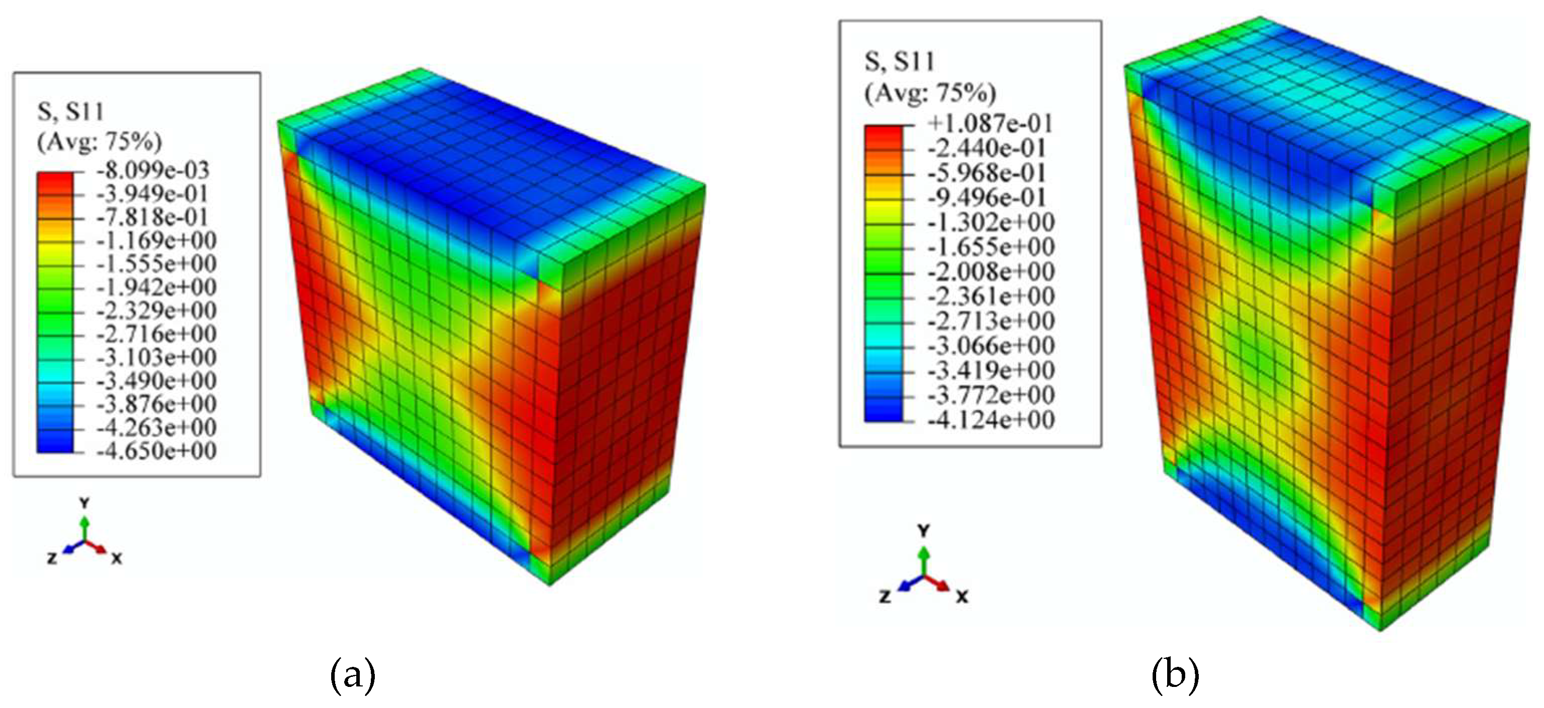
Figure 4.
Effect of the height/thickness ratio. Adapted by the authors from [33].
Figure 4.
Effect of the height/thickness ratio. Adapted by the authors from [33].
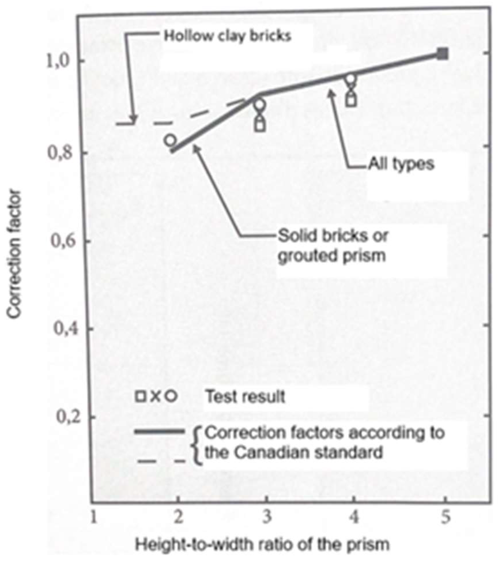
Figure 5.
Clay units characteristics.
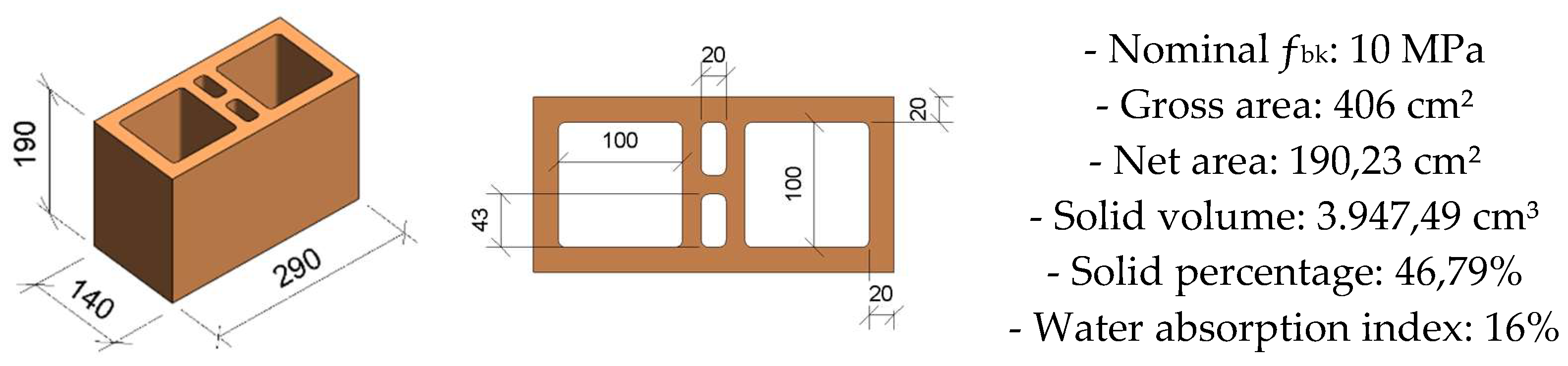
Figure 8.
Compressive strength of the units.
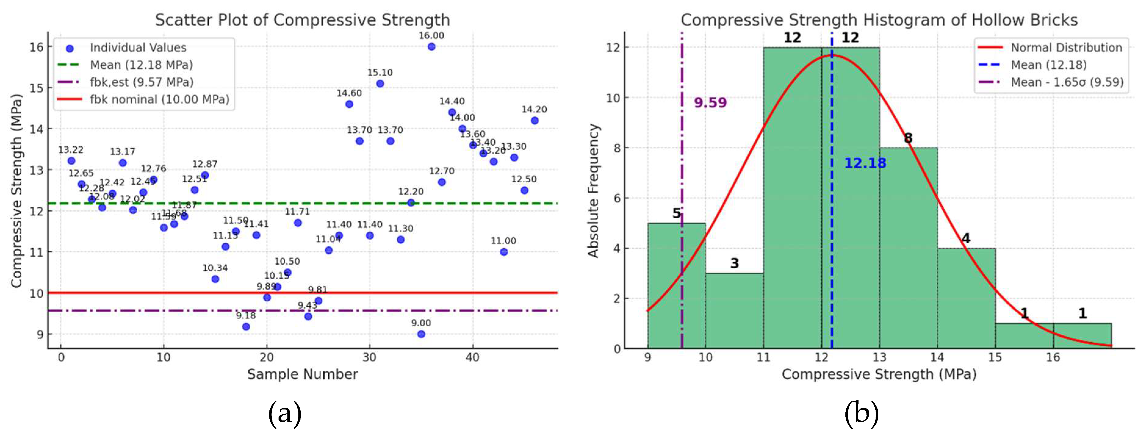
Figure 9.
Compressive strength of the two-course masonry specimens.
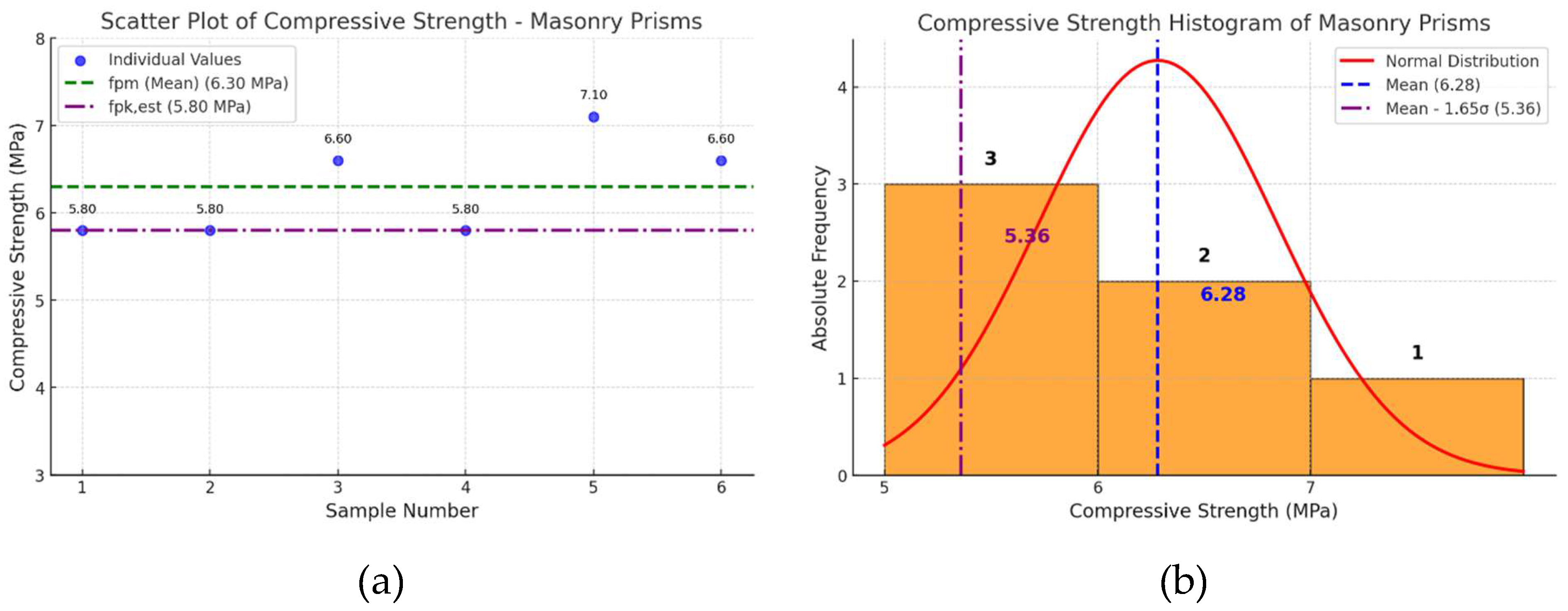
Figure 10.
Failure mode.
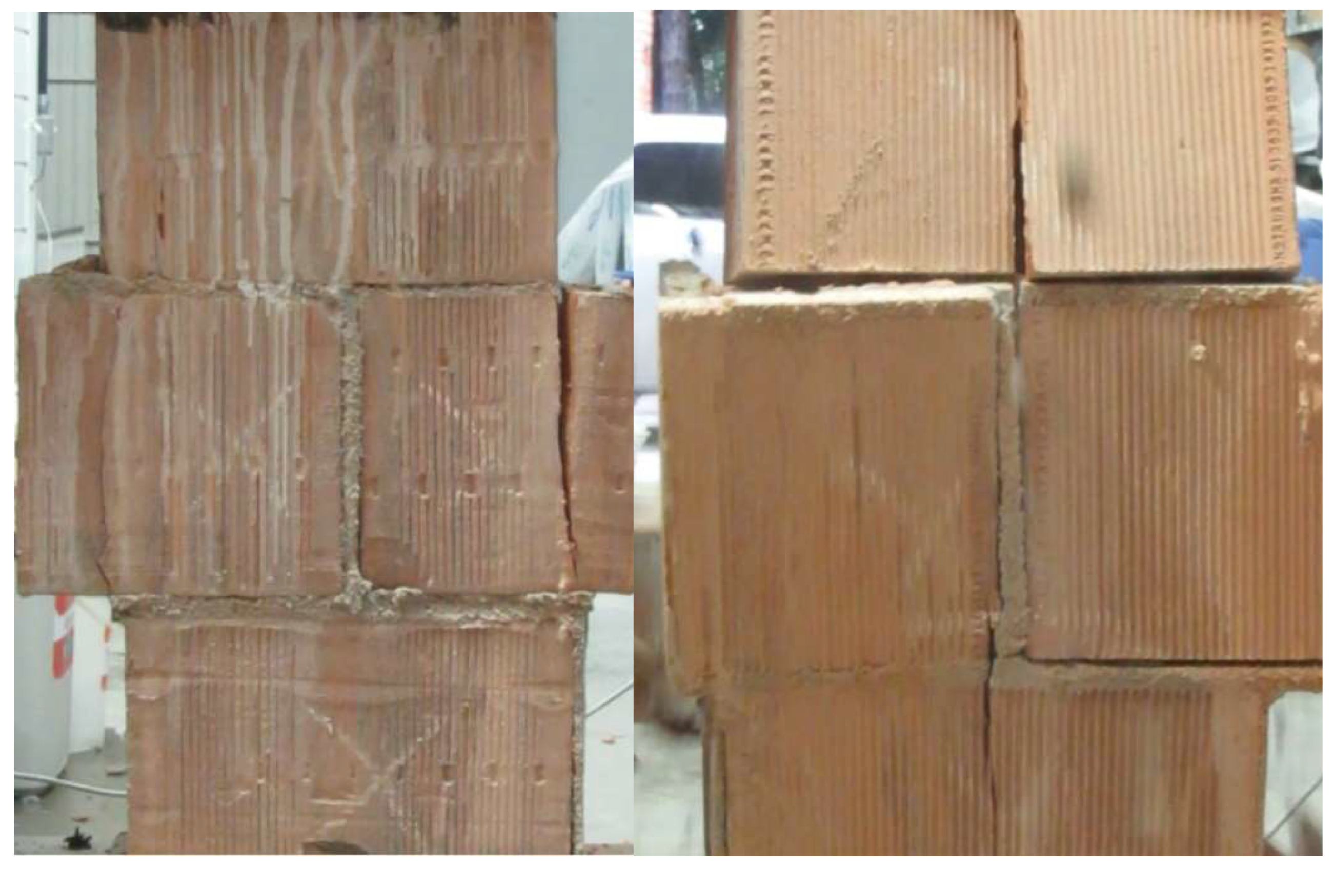
Figure 11.
Compressive strength of the three-course masonry specimen, extracted from full-scale masonry.
Figure 11.
Compressive strength of the three-course masonry specimen, extracted from full-scale masonry.
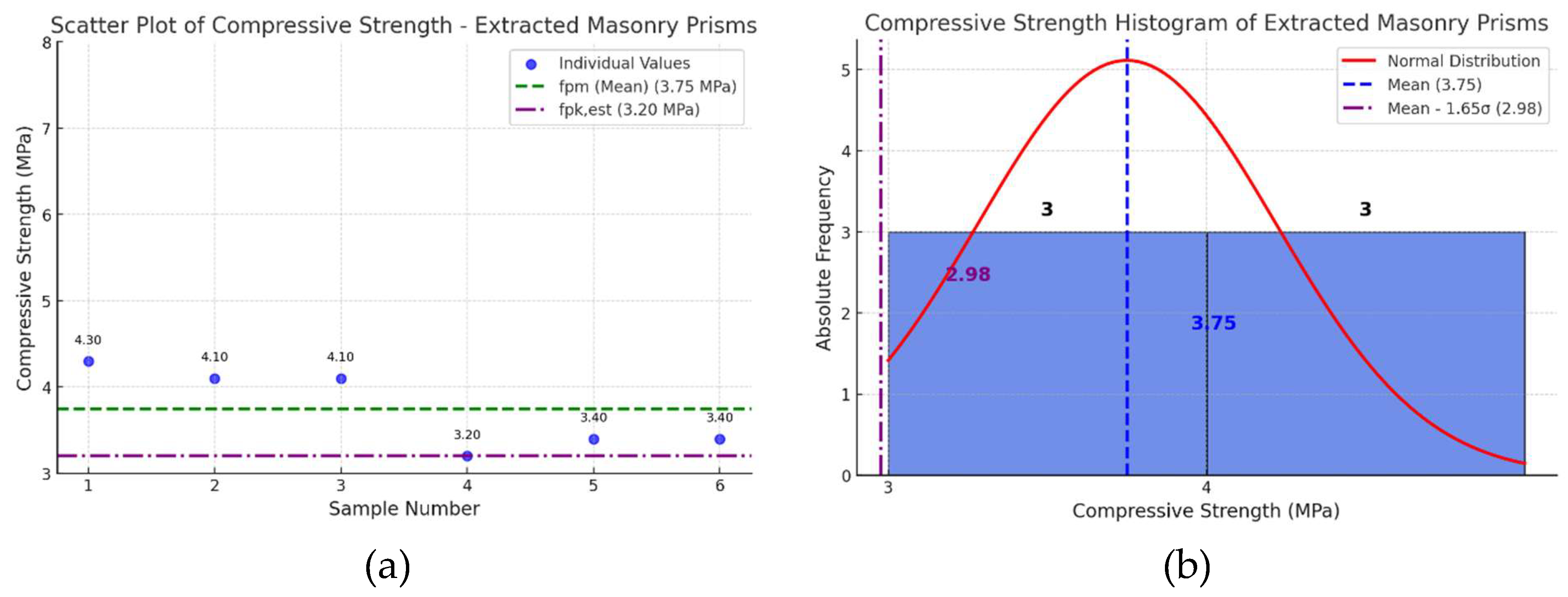
Table 2.
Compressive strength of the units.
| Specimen | Compressive strength (MPa) |
| 1 | 13,22 |
| 2 | 12,65 |
| 3 | 12,28 |
| 4 | 12,08 |
| 5 | 12,42 |
| 6 | 13,17 |
| 7 | 12,02 |
| 8 | 12,45 |
| 9 | 12,76 |
| 10 | 11,59 |
| 11 | 11,68 |
| 12 | 11,87 |
| 13 | 12,51 |
| 14 | 12,87 |
| 15 | 10,34 |
| 16 | 11,13 |
| 17 | 11,50 |
| 18 | 9,18 |
| 19 | 11,41 |
| 20 | 9,89 |
| 21 | 10,15 |
| 22 | 10,50 |
| 23 | 11,71 |
| 24 | 9,43 |
| 25 | 9,81 |
| 26 | 11,04 |
| 27 | 11,40 |
| 28 | 14,60 |
| 29 | 13,70 |
| 30 | 11,40 |
| 31 | 15,10 |
| 32 | 13,70 |
| 33 | 11,30 |
| 34 | 12,20 |
| 35 | 9,0 |
| 36 | 16,0 |
| 37 | 12,70 |
| 38 | 14,40 |
| 39 | 14,0 |
| 40 | 13,60 |
| 41 | 13,40 |
| 42 | 13,20 |
| 43 | 11,0 |
| 44 | 13,30 |
| 45 | 12,50 |
| 46 | 14,20 |
Table 3.
Compressive strength of the two-course masonry specimens.
| Specimen | Compressive strength (MPa) |
| 1 | 5,80 |
| 2 | 5,80 |
| 3 | 5,80 |
| 4 | 6,60 |
| 5 | 7,10 |
| 6 | 6,60 |
Table 4.
Compressive strength of the three-course masonry specimen, extracted from full-scale masonry.
Table 4.
Compressive strength of the three-course masonry specimen, extracted from full-scale masonry.
| Specimen | Compressive Strength (MPa) |
| 1 | 4,30 |
| 2 | 4,10 |
| 3 | 4,10 |
| 4 | 3,20 |
| 5 | 3,40 |
| 6 | 3,40 |
Disclaimer/Publisher’s Note: The statements, opinions and data contained in all publications are solely those of the individual author(s) and contributor(s) and not of MDPI and/or the editor(s). MDPI and/or the editor(s) disclaim responsibility for any injury to people or property resulting from any ideas, methods, instructions or products referred to in the content. |
© 2025 by the authors. Licensee MDPI, Basel, Switzerland. This article is an open access article distributed under the terms and conditions of the Creative Commons Attribution (CC BY) license (http://creativecommons.org/licenses/by/4.0/).
Copyright: This open access article is published under a Creative Commons CC BY 4.0 license, which permit the free download, distribution, and reuse, provided that the author and preprint are cited in any reuse.


