Submitted:
03 April 2025
Posted:
04 April 2025
You are already at the latest version
Abstract
This paper proposes a novel maximum power point tracking (MPPT) strategy for renewable energy systems using Input Impedance Control (I²C) in power electronic converters, combined with an adaptive nonlinear controller. Unlike conventional voltage- or current-based methods, the I²C-MPPT approach leverages the maximum power transfer theorem by dynamically matching the converter’s equivalent input impedance to the source’s internal impedance. The adaptive nonlinear controller, designed using the Lyapunov stability theory, estimates system uncertainties and provides superior performance compared to traditional PI controllers. The proposed approach is validated through both simulations in MATLAB and experimental implementation using a DSP-based controller. Practical results confirm the controller’s effectiveness in maintaining maximum power transfer under dynamic variations in source parameters, demonstrating improved settling time and robust operation. These findings underscore the potential of the I²C approach for enhancing the efficiency and reliability of renewable energy systems.
Keywords:
adaptive control
; I2C approach
; Lyapunov-based controller
; MPPT
1. Introduction
The global shift toward renewable energy resources has accelerated due to the challenges posed by global warming, the depletion of fossil fuels, and the increasing demand for sustainable energy solutions. Renewable generators such as PhotoVoltaic (PV) systems, thermoelectric generators, and wind turbines offer promising alternatives to conventional energy sources. However, the inherent variability of these systems, driven by fluctuating environmental factors, presents significant challenges in achieving efficient energy utilisation. One effective way to address these challenges is through Maximum Power Point Tracking (MPPT) techniques, which aim to maximise energy extraction under varying operating conditions.
Among the most widely used MPPT methods are the Perturb and Observe (P&O) and Incremental Conductance (INC) techniques [1]. These methods are valued for their simplicity and ease of implementation, but they suffer from critical drawbacks. Specifically, P&O methods introduce steady-state oscillations around the maximum power point (MPP) and struggle to adapt to rapid environmental changes. Moreover, although these methods incorporate feedback mechanisms, they are not classified as model-based controllers from a control theory perspective. Consequently, their effectiveness diminishes in complex and dynamic operating scenarios where more robust and adaptive solutions are required [2].
Several advanced MPPT techniques have been proposed to enhance the efficiency and response time of PV systems. One such approach is the use of Fuzzy Logic Control (FLC) and Model Predictive Control (MPC), as analysed in [3]. While FLC demonstrates superior adaptability to dynamic irradiance changes, achieving an average MPPT efficiency of 98.298%, it still relies on heuristic rule-based decision-making, which can be challenging to tune optimally for varying operating conditions. Additionally, FLC methods often exhibit steady-state oscillations around the MPP due to their lack of a precise convergence criterion. On the other hand, MPC provides predictive capabilities but requires a high computational burden, leading to slower response times compared to FLC. Moreover, MPC depends on accurate system modelling, making it less robust against parameter uncertainties.
Artificial intelligence-based MPPT methods proposed in [4] offer predictive capabilities by forecasting irradiance variations and estimating the MPP voltage through a feedforward neural network. While this approach demonstrates superior tracking performance across different weather conditions, its reliance on historical irradiance data makes it susceptible to prediction errors in rapidly fluctuating environments. Furthermore, neural network-based MPPT methods often require extensive training datasets and computationally intensive real-time implementation, limiting their feasibility in embedded system applications.
Metaheuristic optimization algorithms, such as the improved Hunter–Prey Optimisation (IHPO) technique proposed in [5], have also been explored for MPPT applications. These algorithms aim to overcome local optima challenges in multi-peaked power-voltage characteristics under shading conditions. While IHPO achieves high efficiency (98.75%) and global tracking capabilities, it requires iterative searches, leading to longer convergence times compared to direct model-based approaches. Additionally, its dependence on population-based optimisation can introduce transient tracking delays and increased computational overhead, making it less suitable for real-time MPPT applications in rapidly changing environments.
Model-based controllers offer a promising alternative for MPPT by leveraging a mathematical representation of the system to improve accuracy and adaptability [6]. Linear Proportional-Integral (PI) controllers, for example, have been extensively used for voltage or current control in renewable energy systems [7]. Their simplicity and cost-effectiveness make them a popular choice. However, PI controllers are often inadequate for wide operational ranges as they exhibit slow transient responses and sensitivity to environmental disturbances. To overcome these limitations, advanced control methods have been introduced.
Fuzzy logic controllers have shown potential in handling system uncertainties and nonlinearities, particularly in renewable energy applications [8]. Despite their advantages, these controllers increase computational complexity and implementation costs. Similarly, hybrid systems incorporating machine learning techniques [9] enhance the adaptability of MPPT controllers but require extensive training data and computational resources, making them less practical for real-time applications. Sliding mode controllers [10], known for their robustness against parameter variations and external disturbances, offer another advanced solution, yet they are hindered by chattering effects that can compromise system reliability [11]. From the perspective of the Maximum Power Transfer (MPT) theorem in electric circuit analysis, MPPT can be conceptualised as an Input Impedance Control (I2C) problem. According to the MPT theorem, maximum power transfer occurs when the equivalent input impedance of the load matches the internal impedance of the source. This insight provides the foundation for a novel I2C-based approach to MPPT, which shifts the focus from conventional voltage or current control strategies to impedance matching. By aligning the converter’s input impedance with the source’s internal impedance, the I2C approach ensures enhanced performance in energy extraction.
In this design framework, the definition of input impedance introduces significant challenges. The input current, a state variable in the system, appears in the denominator of the impedance equation, and the system is inherently nonlinear as a result. Furthermore, model parameters such as internal resistance and open-circuit voltage are highly dependent on the operating point, particularly in PV generators. These dependencies result in parameter uncertainties that must be addressed to ensure reliable operation.
To address the challenges posed by the inherent nonlinearity of the system, this paper first introduces an innovative method to linearise the system and model it as a first-order transfer function, referred to as the I2C model. While this linearised model is effective under certain conditions, its validity diminishes over a wide range of operating changes and in the presence of significant model uncertainties. To overcome these limitations, an adaptive Lyapunov-based nonlinear controller is proposed. This controller is designed to estimate and compensate for parameter uncertainties, ensuring robustness and superior performance across a wide range of operating conditions. By leveraging the Lyapunov stability theory, the adaptive controller offers a fast dynamic response, enhanced stability, and resilience to environmental variations, making it a promising solution for addressing the complexities of nonlinear renewable energy systems.
In summary, this paper presents a groundbreaking MPPT approach, termed the Input Impedance Control (I2C) strategy. By introducing a paradigm shift from traditional voltage or current control methods to impedance matching, the proposed I2C method directly addresses the limitations of existing techniques. A detailed comparison of the developed controllers demonstrates the significant advantages of the adaptive nonlinear controller in terms of robustness, dynamic response, and performance under varying conditions. Comprehensive MATLAB simulations further validate the effectiveness of the proposed approach, showcasing its ability to enhance the efficiency and stability of renewable energy systems. This contribution not only advances the state of the art in MPPT but also establishes a novel framework for sustainable energy optimisation.
2. I2C-MPPT Approach for Renewable Energy Sources
In this section, the details of the I2C-MPPT approach proposed for renewable energy systems are explained. The basic structure of the system is illustrated in Figure 1. It employs a synchronous DC-DC boost converter to achieve MPP operation for the PV generator. The solar energy is transferred to a battery, which serves as the converter's load. It is important to note that the proposed structure is not limited to PV generators but can also be extended to a wide range of renewable energy sources, such as thermoelectric and piezoelectric generators. The use of a battery as the load is a common practice in this context; however, the I2C-MPPT approach can also accommodate other load types, including resistive loads.
2.1. Input Impedance of the DC-DC Boost Converter (Zin)
Considering the circuit depicted in Figure 1, the input impedance (Zin) of the DC-DC boost converter can be defined as:
where and are the output voltage and current of the PV generator respectively. For steady-state operation of the boost converter, the converter voltage gain can be expressed as:
where is the battery voltage, and is the duty cycle of the boost converter. From this, the PV voltage can be expressed as follows:
Similarly, the input current of the PV generator can be written as:
where is the battery current. Substituting this into (1), the equivalent input impedance of the converter can be calculated:
This shows that the input impedance of the converter can be directly controlled by adjusting the converter’s duty cycle. Furthermore, under steady-state conditions, if a fixed duty cycle is applied to the converter, the DC-DC boost converter can be modeled as a resistor.
2.2. I2C-MPPT Approach
The operating point of the system, defined by the pair (VPV, x1), is determined by the intersection of the I-V curve of the PV generator and the load line, , as discussed in the previous section (Equation 5). Notably, the input impedance Zin can be controlled by adjusting the converter’s duty cycle. Therefore, the duty cycle and input impedance must be carefully tuned such that the operating point settles at the MPP, as shown in Figure 2.
At the MPP, the input impedance is given by:
where and are the voltage and current at the MPP, respectively. If the values of and are known, can be calculated and used as a reference for the closed-loop controller shown in Figure 3.
This control approach, referred to as I2C-MPPT, focuses on controlling the equivalent input impedance rather than relying on traditional voltage or current feedback signals within the closed-loop system.
2.3. Reference Signal Estimation
To estimate the reference signal for the controller, we leverage the improved fractional open-circuit voltage () and short-circuit current () methods, as outlined in recent literature [12]. According to Equation (6), the reference signal requires the values of and in PV applications. These values can be approximated as and where and are constants that relate the open-circuit voltage and short-circuit current to the MPP values. These constants and are typically derived from empirical measurements [12]. To estimate MPP values, and must be obtained from the synchronous DC-DC boost converter system. As shown in Figure 1, when both switches S1 and S2 are turned off, the output voltage of the PV system equals the open-circuit voltage . For measuring the short-circuit current, when S1 is on and S2 is off, and after the system response has settled, the inductor behaves as a short circuit, allowing the short-circuit current to be measured. These measurements of and , in conjunction with the fractional open-circuit and short-circuit methods, enable the estimation of .
3. System Modelling and I2C-MPPT Design
In this section, the system modelling and I2C-MPPT closed-loop controller design for renewable generators is presented. Considering the proposed approach, the equivalent input impedance of the converter is controlled to match the equivalent internal impedance of the renewable generator. Consequently, the renewable generator can be represented using the Thevenin equivalent circuit, consisting of a voltage source in series with a resistor. Notably, their values depend on the operating point and characteristics of the renewable generator. For example, in thermoelectric generators and piezoelectric generators, the open-circuit voltage and internal resistance remain approximately constant across a wide range of operation. However, for PV generators, these values are highly dependent on the operating point. At a specific operating point, the PV generator can still be modelled using the same approach. From a controller design perspective, the values of open-circuit voltage and internal resistance are uncertain. Hence, modelling the input voltage source as a Thevenin circuit is an acceptable assumption if the model parameters are treated as uncertain values.
3.1. System Modelling
The system model assumes that the converter operates at a sufficiently high switching frequency to ensure Continuous Conduction Mode (CCM). Notably, Discontinuous Conduction Mode (DCM), the input current ripple becomes significant, causing the operating point of the renewable generator to fluctuate widely around the MPP during steady-state operation. This fluctuation adversely affects system performance. Consequently, CCM operation is preferred for MPPT applications. Considering the switching states of the converter in CCM:
- (1)
- Switching State 1 (S1: ON, S2: OFF):
In this state, the load (battery) is disconnected from the input source. Assuming the inductor current as the state variable and ideal switch operation (short circuit when ON and open circuit when OFF), the time derivative of the state variable can be expressed as:
- (2)
- Switching State 2 (S1: OFF, S2: ON):
In this state, the energy stored in the inductor during the previous mode is transferred to the load battery. The time derivative of the state variable in this mode is given by:
By combining these two equations and applying an averaged state-space model, the system dynamics can be expressed as:
where represents the duty cycle. This modelling approach provides a foundation for analysing and designing the control systems.
3.2. Model Linearisation and PI Control
From the perspective of controller design, the input variable is defined as , and the output is defined as . Consequently, the system transfer function is expressed as . Considering the system nonlinearity and to analyse it in small signal terms, small perturbations around the steady-state values are introduced:
where , , and are steady-state values and , , and are small-signal variables.
Substituting (10) and (11) into the original state-space equation in (9):
Separating the DC and ac terms in (11), and assuming , as the time derivative of DC component is zero:
Hence, the first term of the transfer function, can be expressed in Laplace domain as:
Replacing (10), (12), and (16) into :
The equation (19) can be written as:
Simplifying further:
Assuming , the DC and ac components can be separated in (21) as follows:
From these equations:
Using (25), the second term of the transfer function, ,can be written as:
The system transfer function can be determined using (18) and (26) as follows:
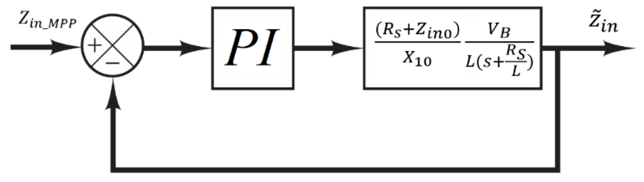
Based on (27), it is shown that the I2C-MPPT system can be approximated using a first order transfer function. The closed-loop block diagram of linear PI controller used to implement the I2C-MPPT system is illustrated in Figure 5.
3.3. Lyapunov Based Adaptive Nonlinear I2C-MPPT Design
Considering the equation used for modeling the input impedance, , the I2C-MPPT system exhibits nonlinear behavior. As a result, the linear controller depicted in Figure 5 is unable to guarantee the stability and robustness of the closed-loop system under significant variations in , , and . To address this limitation, this paper proposes a novel adaptive nonlinear controller. In the proposed design, all system parameters are treated as uncertain, and adaptive rules are derived based on the Lyapunov stability criteria to estimate and compensate for the variations in these uncertain parameters effectively.
To design the adaptive nonlinear controller, the error is defined as:
where is the reference value of input impedance. So, the error dynamic can be extracted:
Assuming as a control input and substituting (9) into (27):
Due to the uncertainty of model parameters in (30), the dynamic of error can be rewritten as follows:
where the state variable is mapped using . Also, the model's uncertain parameters are introduced based on the following equations:
Assuming , , and as estimations of the uncertain parameters, time-derivative of error in (30) can be rewritten as:
To develop the adaptive nonlinear controller, the Lyapunov function, , the I2C-MPPT system is introduced below where and is called parameter estimation weight (for =1,2, and 3).
Time derivative of the Lyapunov function is:
Assuming , , and :
Substituting from (34) into (37):
Assuming:
and:
the time-derivate of the Lyapunov function in (38) will reduce to which is a semi-definite negative function if Hence, those assumptions in (39)-(42) result in the asymptotic stability of the closed-loop system.
The nonlinear control law can be formulated based on (39):
Furthermore, the estimation rules for uncertain parameters in (31)-(33) can be extracted using (40)-(42):
4. Simulation and Experimental Results
To investigate the performance of the proposed adaptive nonlinear I2C-MPPT approach against parameter variations such as open-circuit voltage (VS) and internal resistance (RS), the power circuit shown in Figure 4 is implemented. The system is validated through both simulations and experimental tests, with the nominal parameter values for both cases specified in Table 1.
The switching frequency (fS) is selected to ensure CCM operation of the converter across the entire operating range.
4.1. Simulation Results
4.1.1. Test 1: Evaluation of the Linearised Model
The linearised model for the I2C-MPPT is evaluated by comparing the closed-loop system’s output shown in Figure 5 with the implemented actual closed-loop system using a PI controller. The comparison results, shown in Figure 6, indicate that the developed linearised model (in equation (27)) accurately tracks the actual response obtained from MATLAB simulations. This validates the correctness of the linearised model for the I2C-MPPT approach.
For all simulations presented for the linear controller, the proportional and integral gains were set to Kp=4 and Ki = 300, respectively. It is noted that, due to the first-order linear approximation in (27), the system’s phase margin is not sensitive to changes in Kp and Ki. The Bode plot of the linearised model, shown in Figure 7, demonstrates a phase margin of approximately 92.8°, confirming system stability for the selected gains.
Figure 5.
Thevenin equivalent circuit representation of the input voltage source, with model parameters considered as uncertain.
Figure 5.
Thevenin equivalent circuit representation of the input voltage source, with model parameters considered as uncertain.
4.1.2. Test 2: Comparison of Linear and Adaptive Nonlinear Controllers
The response of the proposed adaptive nonlinear controller is compared with the linear controller. Figure 8 presents the converter’s input voltage (Vin) and current (x1) responses relative to their reference values for both linear and nonlinear controllers. Given an open-circuit voltage of VS = 10V, the reference values for Vin and current x1 are:
Both controllers achieve zero steady-state error, ensuring that the converter operates at the MPP with an input impedance matching the reference value. However, the proposed adaptive nonlinear controller exhibits significantly faster transient response, demonstrating superior performance during dynamic conditions.
4.1.3. Test 3: Response to Open-Circuit Voltage Changes
The robustness of the adaptive nonlinear controller against changes in VS is evaluated in this test. Figure 9 shows the system’s response to a step change in VS from 15 V to 10 V at t = 0.075s. According to the MPT theorem changes from 7.5 V to 5 V and changes from 7.5 A to 5 A. Simulation results confirm that the adaptive nonlinear controller remains stable and robust, successfully tracking the new reference values.
4.1.4. Test 4: Response to Internal Resistance Changes
The system’s response to a step change in RS from 1Ω to 1.25Ω is evaluated in this test. Figure 10 illustrates the simulation results. The input voltage reference value for this test is . Also, changes from 5A to 4A. The adaptive nonlinear controller successfully maintains stable operation, tracking the desired references despite changes in RS.
4.1.5. Test 5: Input Impedance Variation
Finally, the variation of the equivalent input impedance (Zin) with respect to VS changes is analysed. At MPP, Zin_ref = Zin-MPP matches the internal resistance (RS). Figure 11 demonstrates that, despite step changes in VS from 15V to 10V, the adaptive nonlinear controller accurately tracks the fixed reference value of Zin_ref = Zin-MPP = RS = 1Ω. This highlights the controller’s robustness and precision in ensuring optimal system operation.
4.2. Experimental Results
The practical implementation of the proposed adaptive nonlinear I²C approach is illustrated in Figure 12-a. To evaluate the controller's dynamic response under parameter uncertainties, an emulator is employed, which can introduce step variations in both the open-circuit voltage and internal resistance by triggering switches S1 and S2, respectively. This setup enables a worst-case scenario evaluation, where the controller must adapt to sudden changes in these uncertain parameters.
To accurately measure the feedback signals, isolated sensors are integrated into the system for input voltage and current measurements, as shown in Figure 12-a. The IL300 DC input photodiode output optocoupler is utilised for voltage sensing, while the LA100 current sensor from the LEM LA series is employed for current measurement. The controller is implemented on a TMS320F DSP platform, where the analogue feedback signals are digitised using internal A/D converters. The control law and estimation equations (43) – (46) are processed within the DSP, and the computed duty cycle is converted into a switching signal via the internal PWM block. To ensure proper isolation between the power converter and the DSP, a switch driver unit acts as an interface, providing significant current gain for fast switching while matching the DSP’s output voltage with the MOSFET gate requirements. This driver is implemented using the CPL-316J-000E BiCMOS/DMOS output optocoupler. The IRL540NPBF, a 36A, 100V N-channel MOSFET, is employed as the main power switch in both the converter and the emulator circuits. Additionally, the MOSFET’s internal antiparallel diode serves as the power diode, as detailed in Figure 12-a. The load consists of two BP7-12-T1 (12V, 7Ah) batteries connected in series. The complete test rig is depicted in Figure 12-b.
The experimental response of the converter is presented in Figure 13, Figure 14 and Figure 15. Figure 13 illustrates the system behaviour during startup. Initially, before the controller is activated, the input current remains at zero, and the open-circuit voltage (15V) is observed at the input port. Upon activation, the input voltage drops and stabilises at half of the open-circuit voltage (7.5V), confirming that the controller operates at the MPP according to the proposed I²C MPPT approach. At this condition, the input impedance matches the internal resistance (Rs=1Ω), resulting in an expected steady-state input current of , which aligns with the measured waveform in Figure 13. Figure 14 presents the dynamic response of the controller to a step change in the open-circuit voltage, where VS is reduced from 15V to 10V. Consequently, the input voltage adjusts to 5V, which remains at half of the new open-circuit voltage, validating that the controller maintains MPPT. The corresponding input current, calculated as , is consistent with the experimental waveform in Figure 14. Lastly, Figure 15 illustrates the system’s response to a step change in the internal resistance from 1Ω to 1.25Ω. It is observed that, despite the resistance variation, the controller continuously adjusts the input voltage to sustain MPP operation as long as the open-circuit voltage remains constant.
It should be noted that the parameters for the adaptive nonlinear controller used in all simulations are K = 1 × 10⁶ and 1 × 10⁻⁴ .
Briefly, the simulation results validate the effectiveness of the proposed adaptive nonlinear I2C-MPPT approach. It demonstrates superior performance in tracking reference values, robustness against parameter variations, and stable operation under dynamic conditions, making it an excellent candidate for renewable energy systems.
5. Conclusions
This paper has introduced a novel approach to MPPT in renewable energy systems by introducing the Input Impedance Control (I2C) strategy, which is a departure from conventional voltage or current-based controllers. Through a comprehensive comparative analysis of adaptive Lyapunov-based nonlinear and Proportional-Integral (PI) controllers, it has been demonstrated that the I2C approach, when integrated with an adaptive Lyapunov-based nonlinear controller, significantly enhances system performance in MPPT applications. The simulation and practical results validate the effectiveness of the proposed adaptive nonlinear I2C-MPPT approach, showing superior dynamic performance, faster rise time, and improved settling time compared to traditional PI controllers. The controller exhibits remarkable robustness, maintaining stability and optimal power tracking under varying operating conditions. Notably, the ability of the adaptive nonlinear controller to handle parameter uncertainties further underscores its practical applicability in real-world renewable energy systems, where such variations are commonplace.
Funding
This research was funded by University of Greenwich grant number KE4 Impact Evaluator FES under Project Code P13540.
Data Availability Statement
The original contributions presented in this study are included in the article/supplementary material. Further inquiries can be directed to the corresponding author(s).
Acknowledgments
The author gratefully acknowledges the support provided by the University of Greenwich through the Research Award (KE4 Impact Evaluator FES) under Project Code P13540. This work is part of the project titled "Maximising Energy Cost Savings with a Novel Multifunctional Controller for Grid-Connected Photovoltaic Systems”.
Conflicts of Interest
The authors declare no conflicts of interest.
References
- S. Khadidja, M. Mountassar and B. M'hamed, "Comparative study of incremental conductance and perturb & observe MPPT methods for photovoltaic system," 2017 International Conference on Green Energy Conversion Systems (GECS), Hammamet, Tunisia, 2017, pp. 1-6. [CrossRef]
- J. Mishra, S. Das, D. Kumar and M. Pattnaik, "Performance Comparison of P&O and INC MPPT Algorithm for a Stand-alone PV System," 2019 Innovations in Power and Advanced Computing Technologies (i-PACT), Vellore, India, 2019, pp. 1-5. [CrossRef]
- Li, Z.; Dewantoro, G.; Xiao, T.; Swain, A. A Comparative Analysis of Fuzzy Logic Control and Model Predictive Control in Photovoltaic Maximum Power Point Tracking. Electronics 2025, 14, 1009. [Google Scholar] [CrossRef]
- Bandara, A.; Ratnayake, K.; Dissanayake, R.; Udawatte, H.; Godaliyadda, R.; Ekanayake, P.; Ekanayake, J. LSTM-Based MPPT Algorithm for Efficient Energy Harvesting of a Solar PV System Under Different Operating Conditions. Electronics 2024, 13, 4875. [Google Scholar] [CrossRef]
- Bandara, A.; Ratnayake, K.; Dissanayake, R.; Udawatte, H.; Godaliyadda, R.; Ekanayake, P.; Ekanayake, J. LSTM-Based MPPT Algorithm for Efficient Energy Harvesting of a Solar PV System Under Different Operating Conditions. Electronics 2024, 13, 4875. [Google Scholar] [CrossRef]
- Abdel-Rahim and, H. Wang, "A new high gain DC-DC converter with model-predictive-control based MPPT technique for photovoltaic systems," in CPSS Transactions on Power Electronics and Applications, vol. 5, no. 2, pp. 191-200, June 2020. [CrossRef]
- J. -S. Ko and D. -H. Chung, "The MPPT control of PV system using the series-connected PI controller," 2016 16th International Conference on Control, Automation and Systems (ICCAS), Gyeongju, Korea (South), 2016, pp. 807-809. [CrossRef]
- S. SIDDULA, "Analysis of Fuzzy Logic Based MPPT Using Incremental Conductance Technique for PV Cell," 2020 International Conference on Smart Technologies in Computing, Electrical and Electronics (ICSTCEE), Bengaluru, India, 2020, pp. 180-185. [CrossRef]
- B. Khelifi, M. A. Zdiri and F. Ben Salem, "Machine Learning for Solar Power Systems-A short tour," 2021 12th International Renewable Energy Congress (IREC), Hammamet, Tunisia, 2021, pp. 1-6. [CrossRef]
- R. Pradhan and B. Subudhi, "Double Integral Sliding Mode MPPT Control of a Photovoltaic System," in IEEE Transactions on Control Systems Technology, vol. 24, no. 1, pp. 285-292, Jan. 2016. [CrossRef]
- Mahdi Salimi, "Practical implementation of the Lyapunov based nonlinear controller in DC-DC boost converter for MPPT of the PV systems, " in Solar Energy, Volume 173, 2018, Pages 246-255, ISSN 0038-092X. [CrossRef]
- Aakash Hassan, Octavian Bass, Mohammad A.S. Masoum, “An improved genetic algorithm based fractional open circuit voltage MPPT for solar PV systems, “ Energy Reports, Volume 9, 2023, Pages 1535-1548, ISSN 2352-4847.
Figure 1.
Equivalent input impedance (Zin) of the converter.

Figure 2.
I-V profile a typical PV generator and corresponding load lines. In the proposed I2C approach, adjusting the converter duty cycle alters the load line and equivalent input impedance (Zin), enabling MPPT of the generator.
Figure 2.
I-V profile a typical PV generator and corresponding load lines. In the proposed I2C approach, adjusting the converter duty cycle alters the load line and equivalent input impedance (Zin), enabling MPPT of the generator.
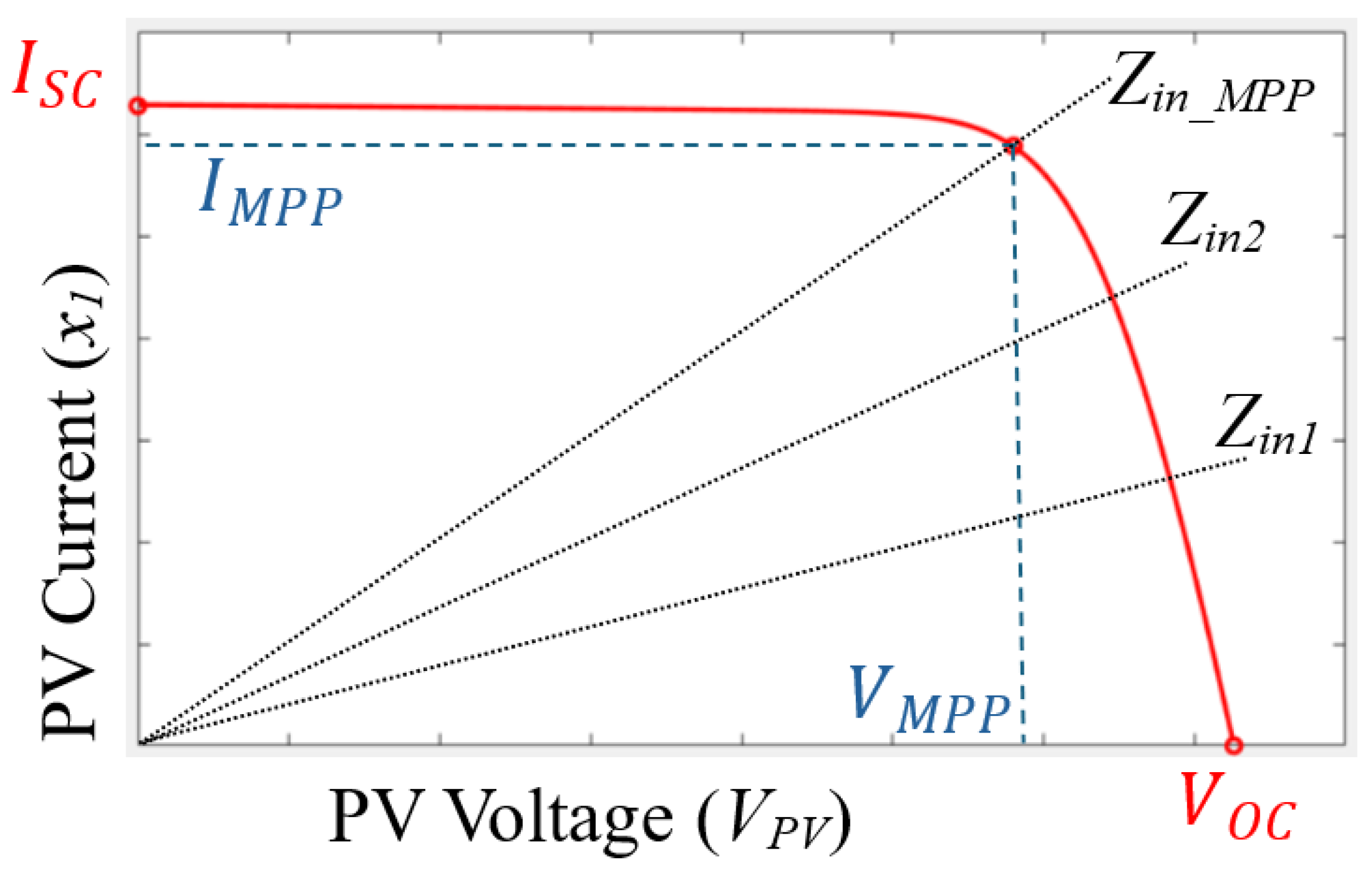
Figure 3.
Structure of the proposed I2C controller.
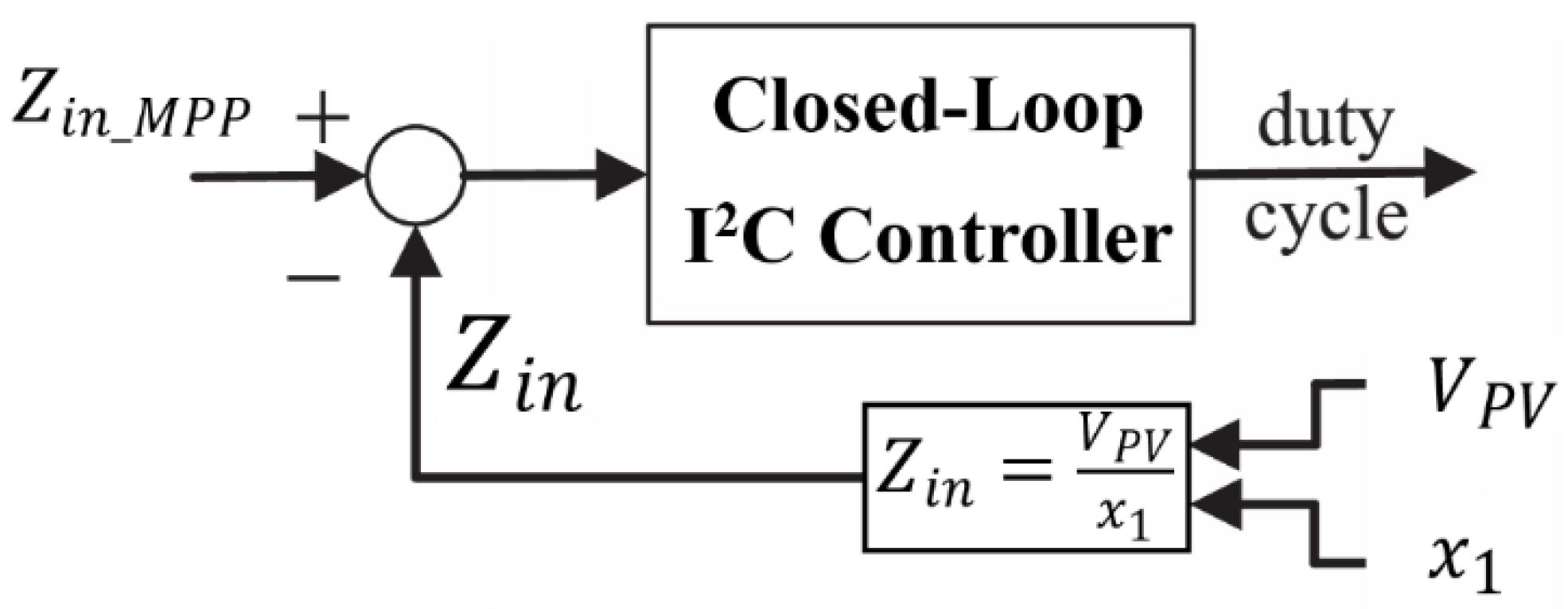
Figure 4.
Thevenin equivalent circuit representation of the input voltage source, with model parameters considered as uncertain.
Figure 4.
Thevenin equivalent circuit representation of the input voltage source, with model parameters considered as uncertain.
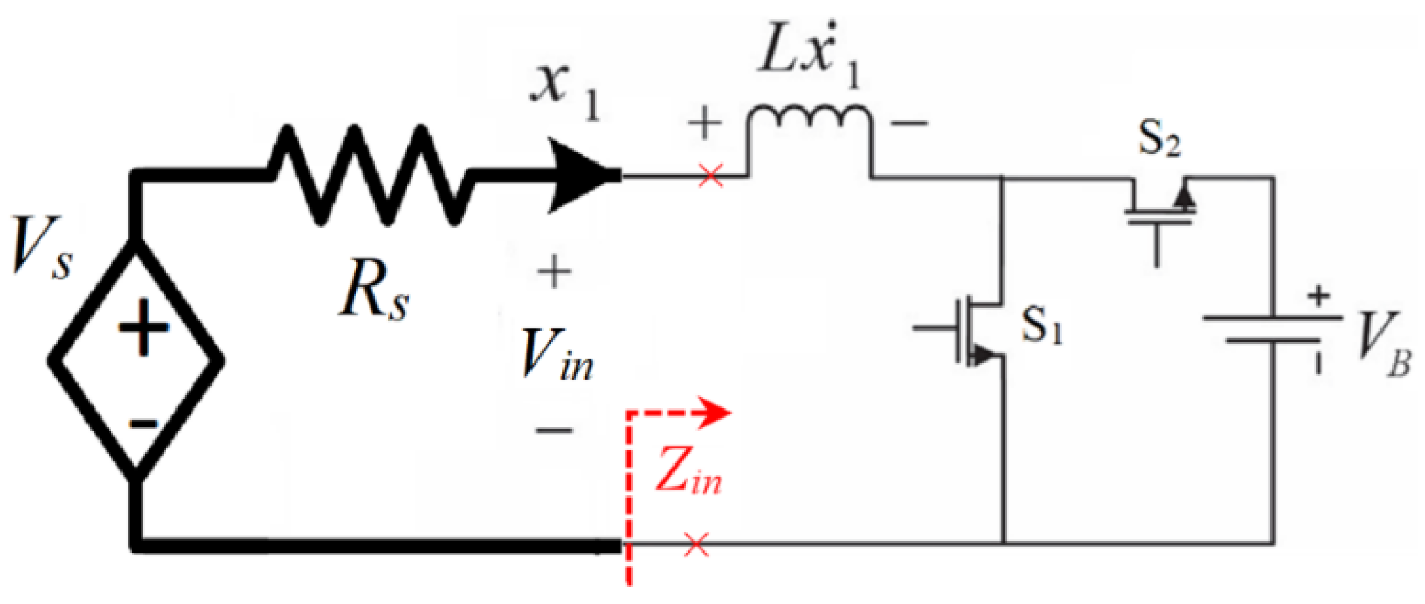
Figure 6.
Comparison of the output of the linearised model, based on the system's transfer function in Figure 5, with the actual response from the Simulink simulation. The results demonstrate the accuracy of the developed linear model for I2C-MPPT.
Figure 6.
Comparison of the output of the linearised model, based on the system's transfer function in Figure 5, with the actual response from the Simulink simulation. The results demonstrate the accuracy of the developed linear model for I2C-MPPT.
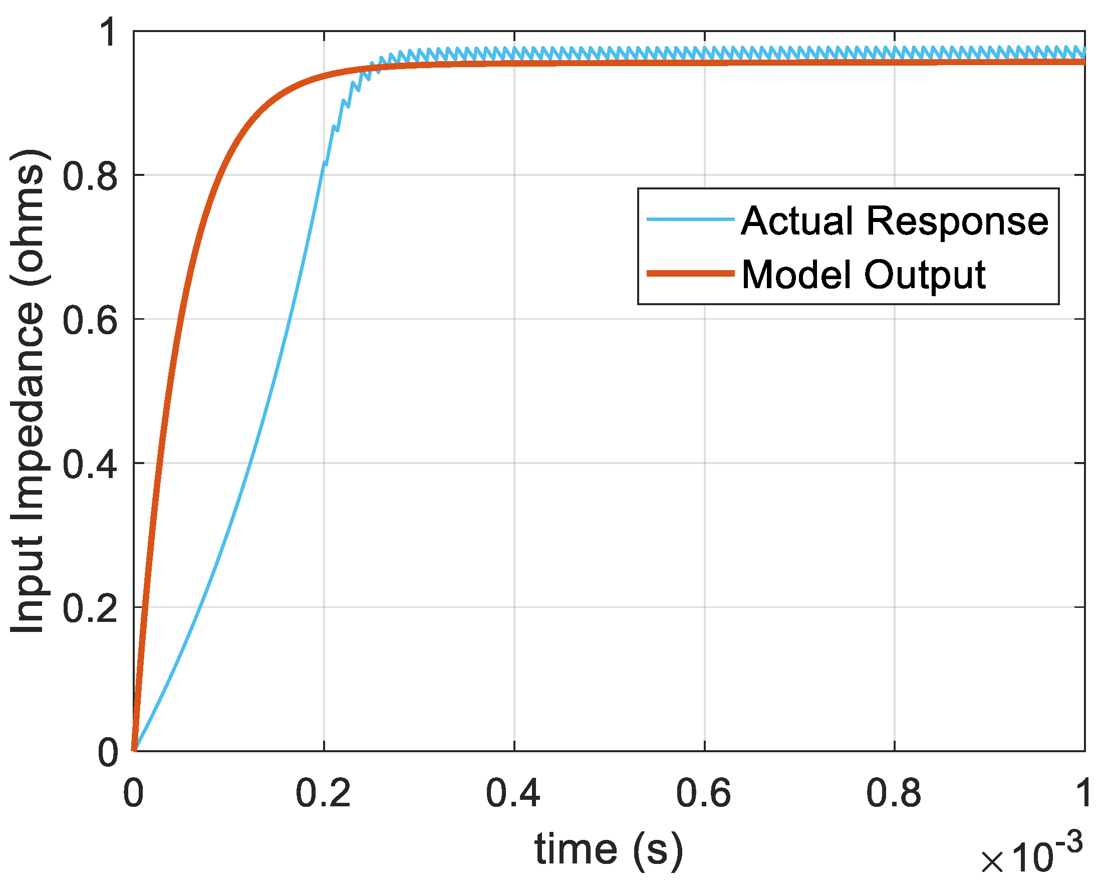
Figure 7.
Bode plot of the linearised I2C-MPPT system, derived from the block diagram shown in Figure 5, illustrating the phase margin and stability of the system.
Figure 7.
Bode plot of the linearised I2C-MPPT system, derived from the block diagram shown in Figure 5, illustrating the phase margin and stability of the system.
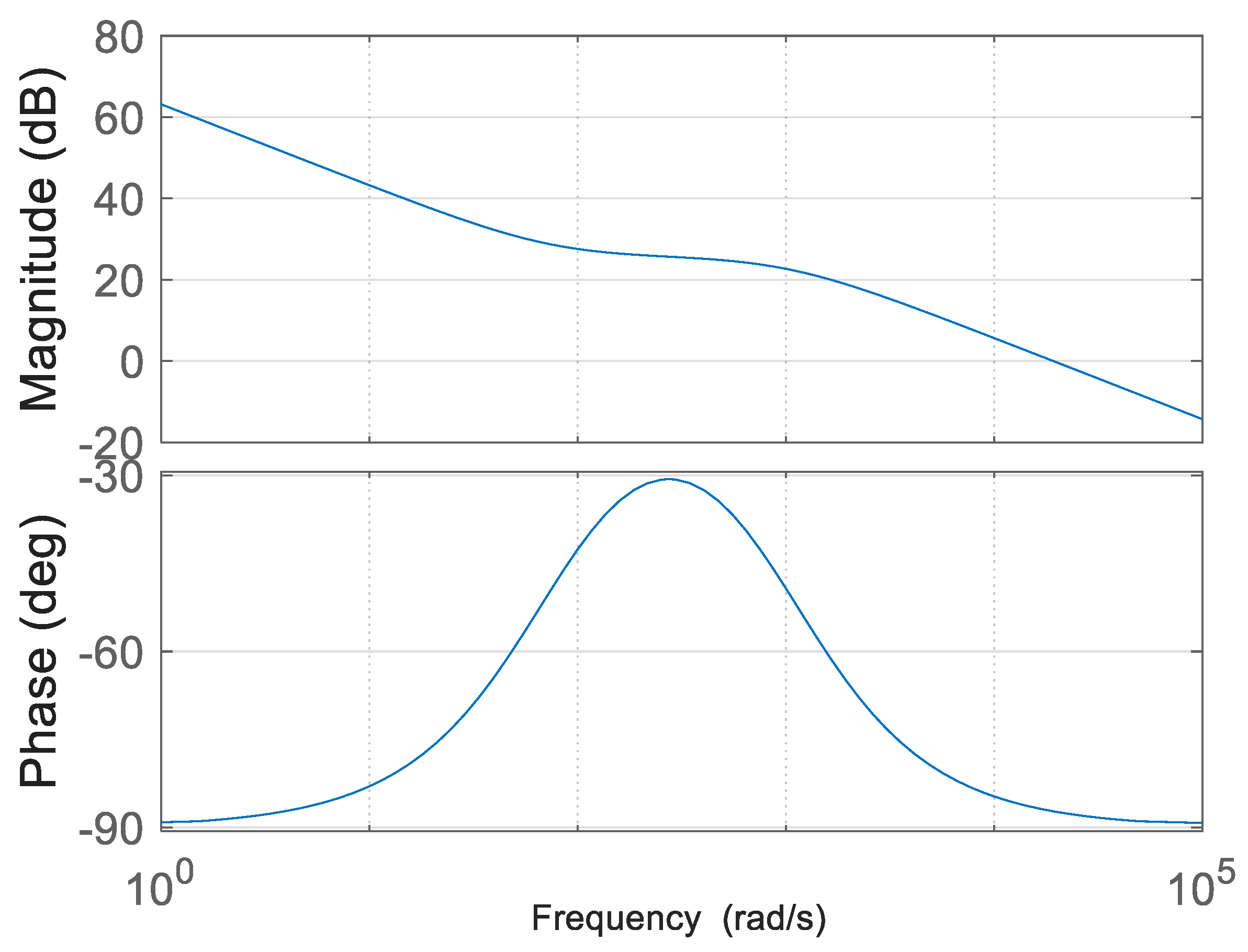
Figure 8.
Comparison of the converter input voltage (Vin) and current (x1) to their reference values for the proposed adaptive nonlinear controller and the linear controller during converter start-up. Both controllers achieve steady-state operation at the MPP, but the adaptive nonlinear controller exhibits a significantly faster transient response, demonstrating superior dynamic performance.
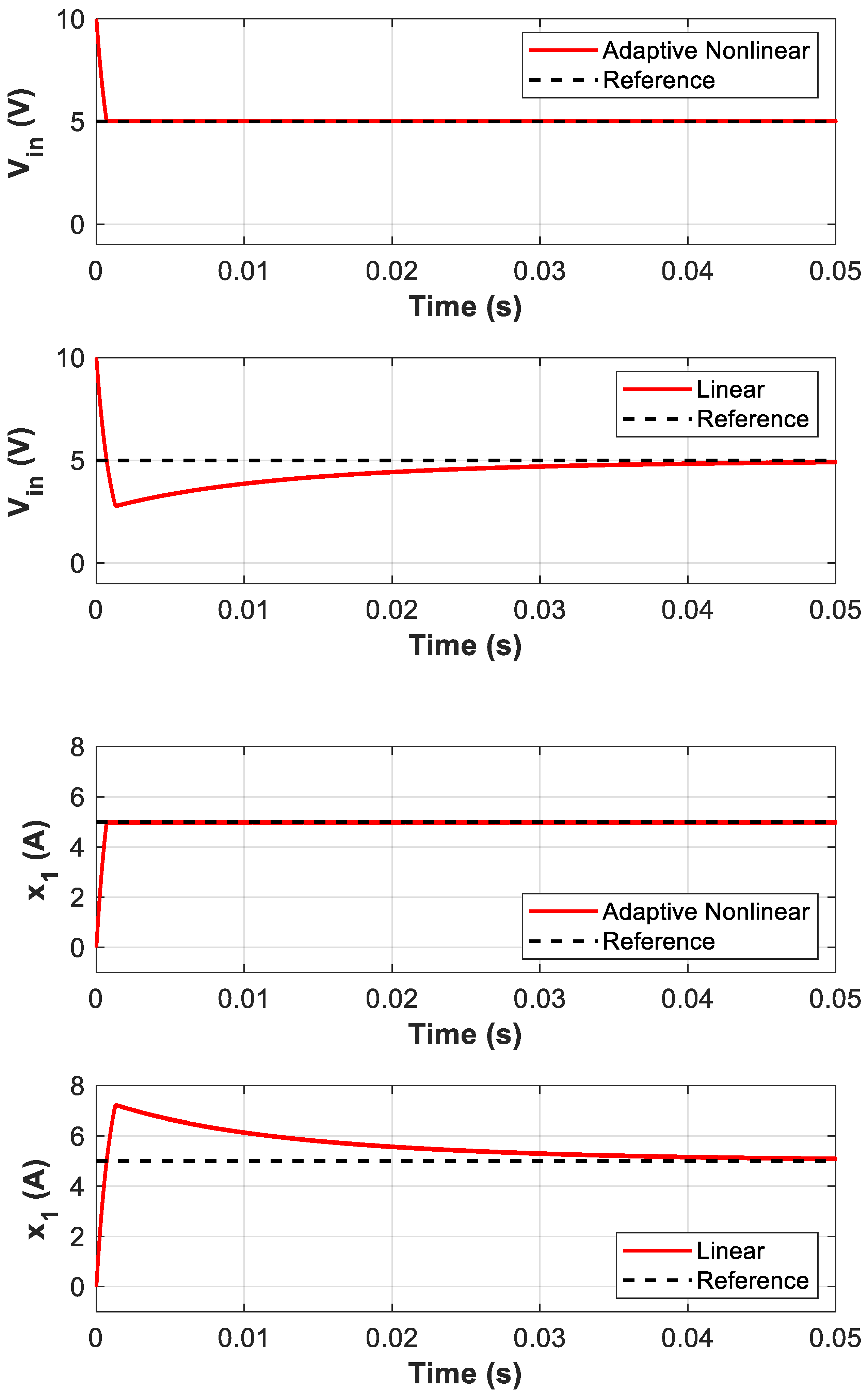
Figure 9.
Response of the adaptive nonlinear controller to a step change in the open-circuit voltage (VS) from 15V to 10V at t = 0.075s. The controller successfully adjusts the input voltage (Vin) and input current (x1) to their new reference values, maintaining stable operation and MPPT.
Figure 9.
Response of the adaptive nonlinear controller to a step change in the open-circuit voltage (VS) from 15V to 10V at t = 0.075s. The controller successfully adjusts the input voltage (Vin) and input current (x1) to their new reference values, maintaining stable operation and MPPT.
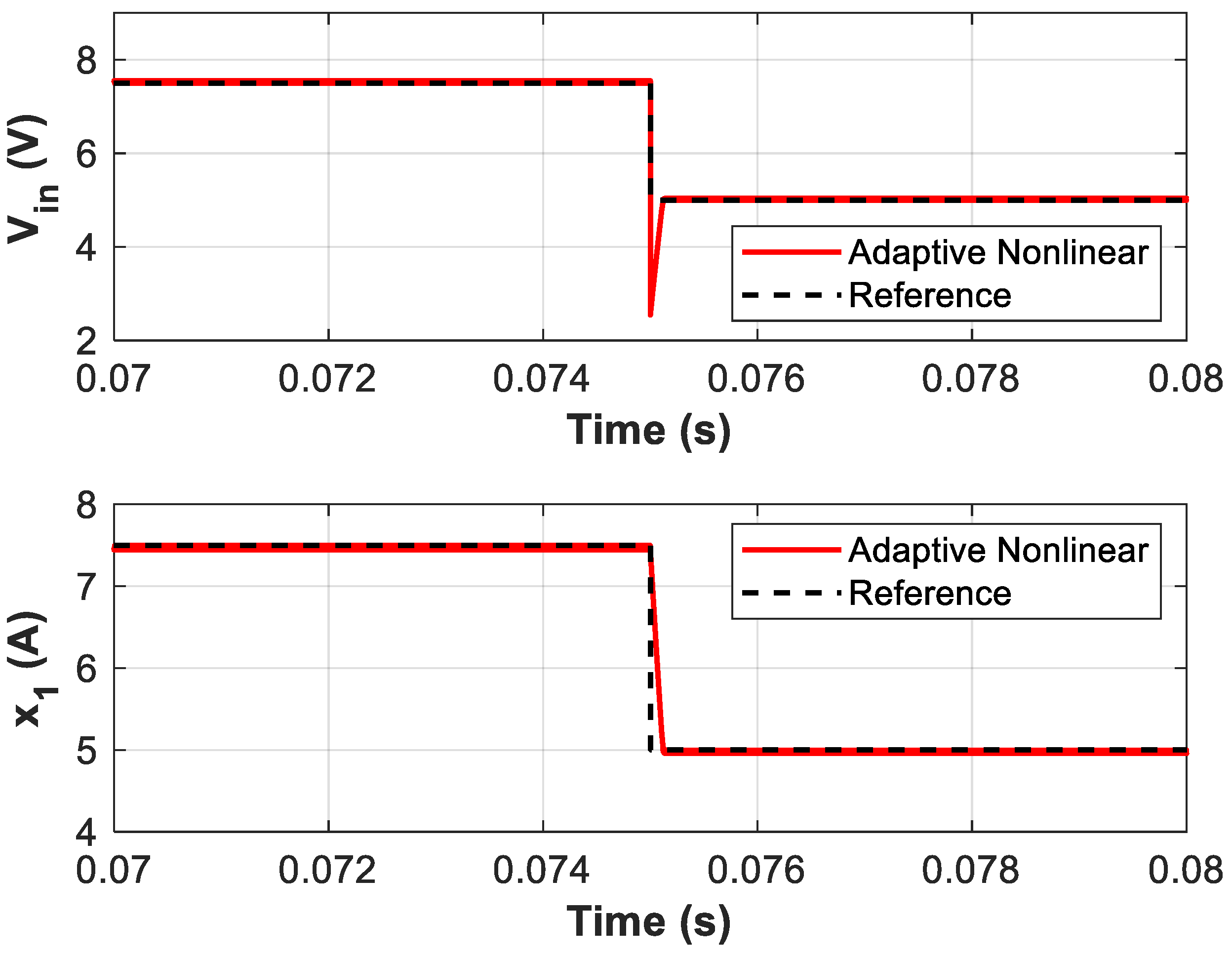
Figure 10.
Response of the adaptive backstepping controller to a step change in the internal resistance (RS) from 1Ω to 1.25Ω at t = 0.075s. The controller effectively tracks the new reference values of the input voltage (Vin) and current (x1), maintaining stable and robust system operation.
Figure 10.
Response of the adaptive backstepping controller to a step change in the internal resistance (RS) from 1Ω to 1.25Ω at t = 0.075s. The controller effectively tracks the new reference values of the input voltage (Vin) and current (x1), maintaining stable and robust system operation.
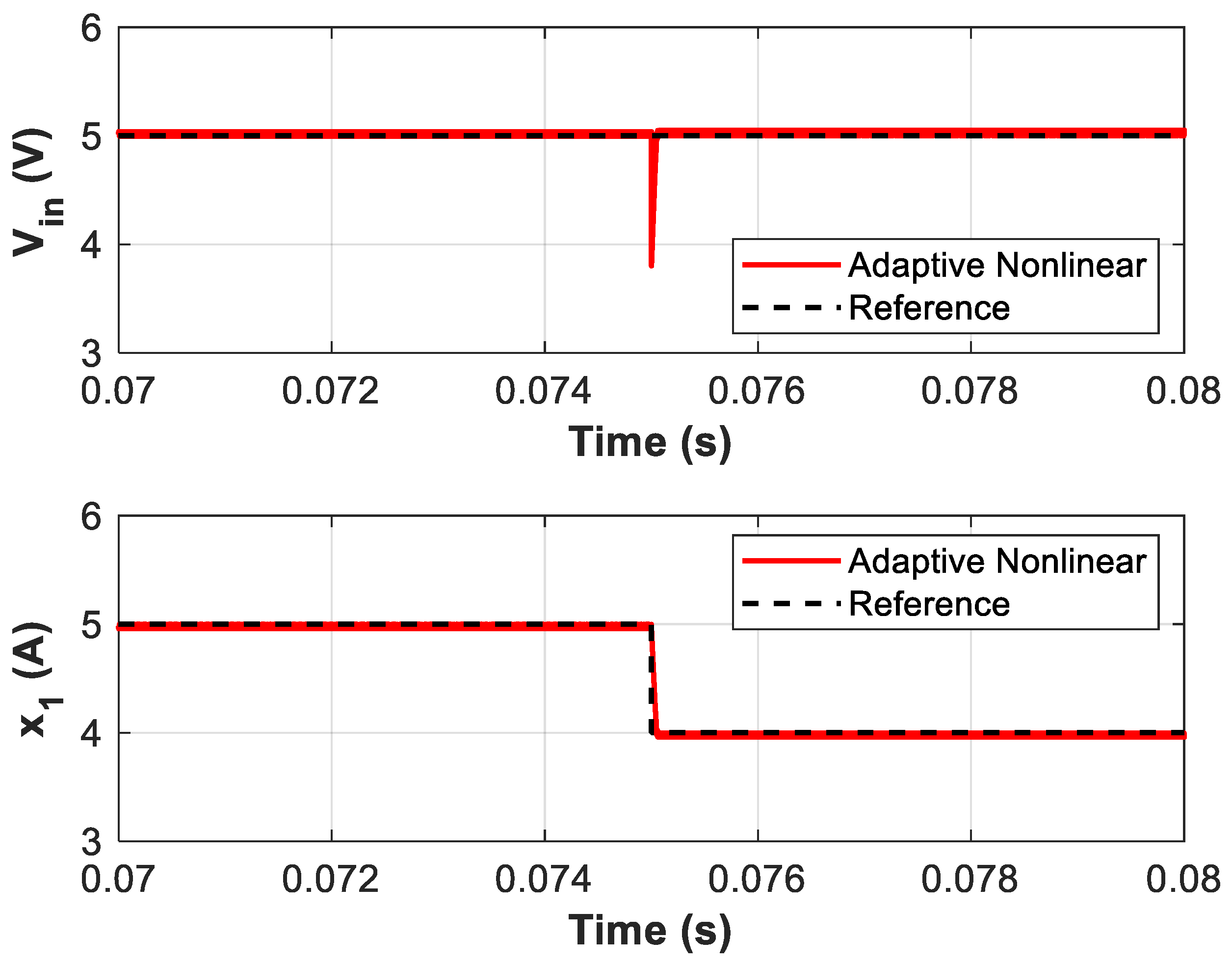
Figure 11.
Variation of the equivalent input impedance (Zin) to step changes in open-circuit voltage (VS) from 15V to 10V. The adaptive nonlinear controller effectively tracks the reference impedance (Zin_ref = Zin-MPP = RS = 1Ω), ensuring stable and optimal operation at MPP.
Figure 11.
Variation of the equivalent input impedance (Zin) to step changes in open-circuit voltage (VS) from 15V to 10V. The adaptive nonlinear controller effectively tracks the reference impedance (Zin_ref = Zin-MPP = RS = 1Ω), ensuring stable and optimal operation at MPP.
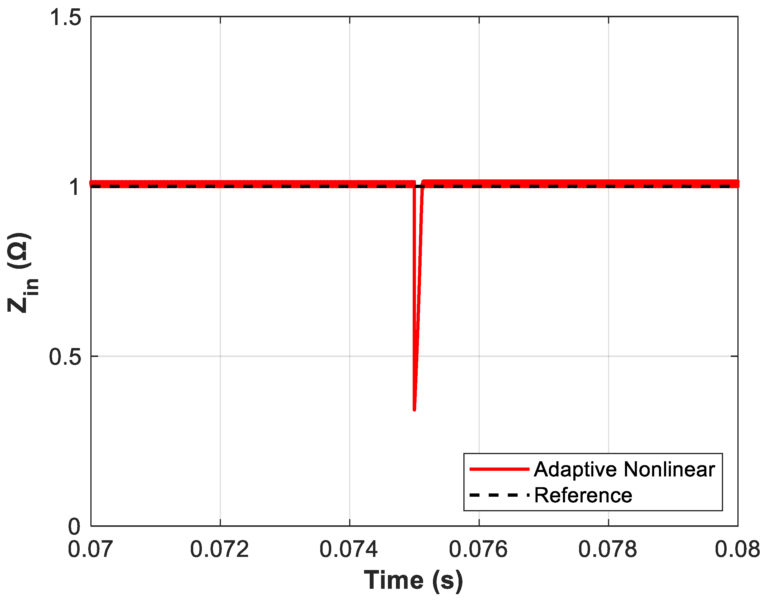
Figure 12.
Schematic of the experimental setup, including the emulator, power circuit, sensor connections, and controller implementation (a), and Experimental test rig illustrating the practical implementation of the proposed I²C-MPPT approach (b).
Figure 12.
Schematic of the experimental setup, including the emulator, power circuit, sensor connections, and controller implementation (a), and Experimental test rig illustrating the practical implementation of the proposed I²C-MPPT approach (b).
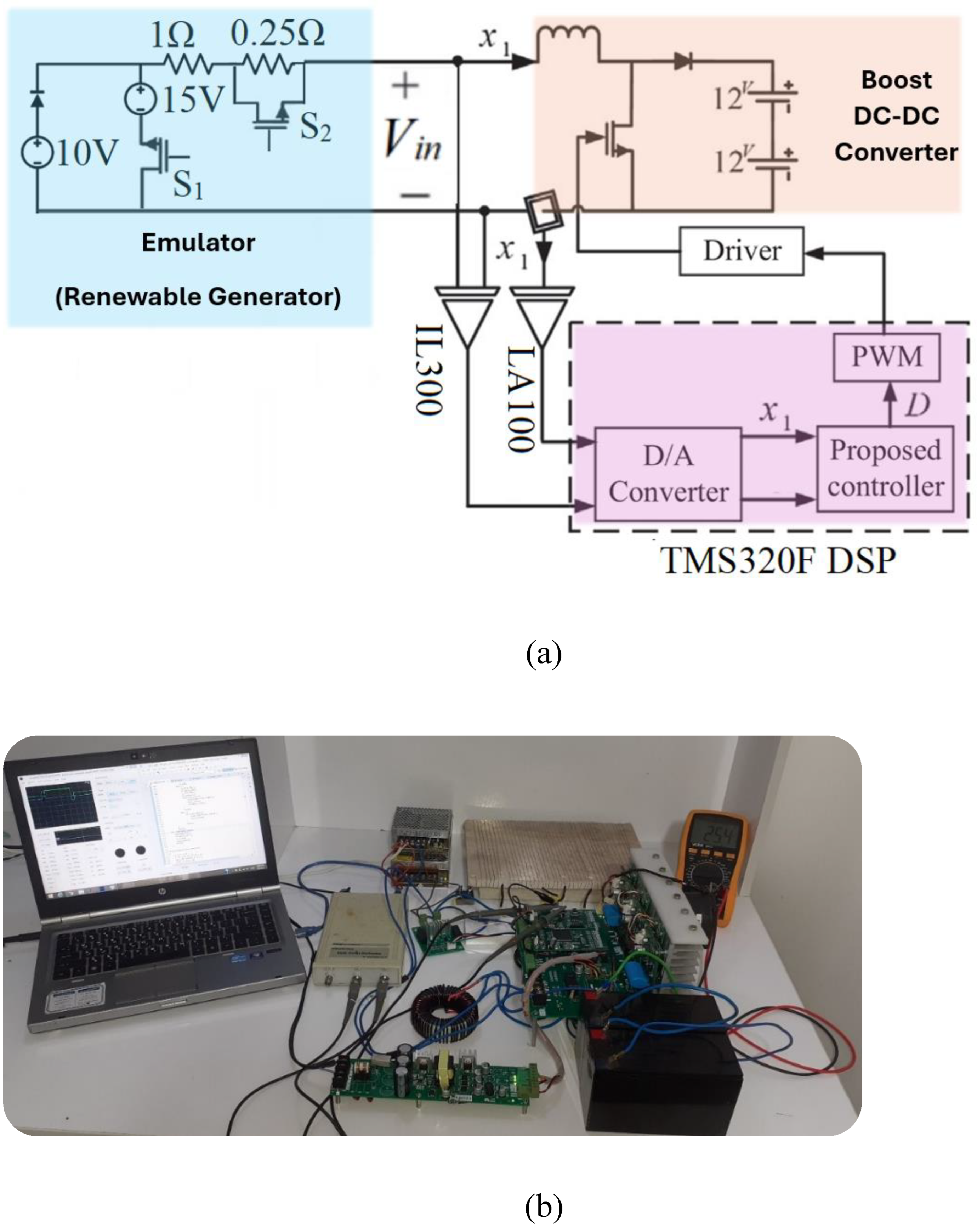
Figure 13.
Practical response of the converter during startup, demonstrating the controller's ability to achieve MPP operation by stabilising the input voltage at half of the open-circuit voltage.
Figure 13.
Practical response of the converter during startup, demonstrating the controller's ability to achieve MPP operation by stabilising the input voltage at half of the open-circuit voltage.
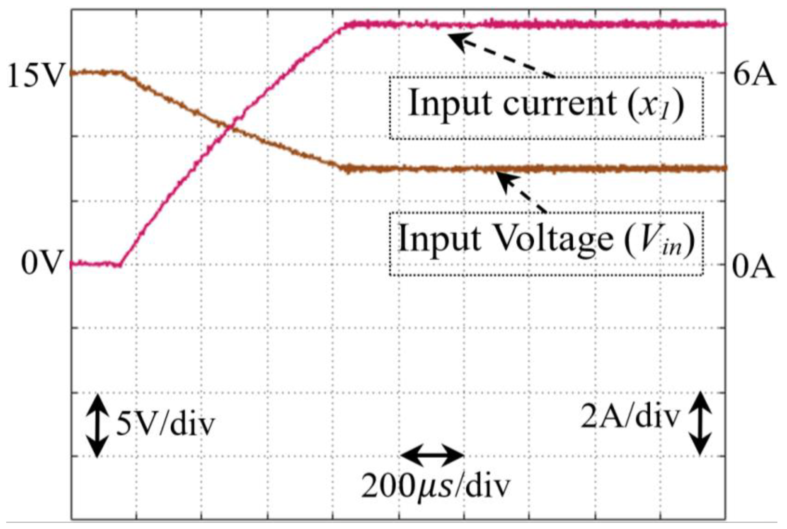
Figure 14.
Dynamic response of the proposed controller to a step change in open-circuit voltage (VS), confirming its ability to maintain MPPT under varying source conditions.
Figure 14.
Dynamic response of the proposed controller to a step change in open-circuit voltage (VS), confirming its ability to maintain MPPT under varying source conditions.
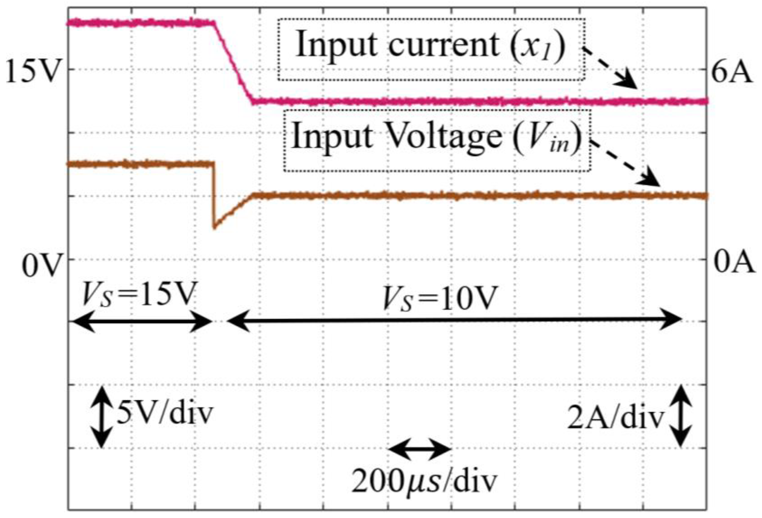
Figure 15.
System response to a step change in internal resistance (RS), illustrating the controller's capability to adapt and sustain MPP operation despite resistance variations.
Figure 15.
System response to a step change in internal resistance (RS), illustrating the controller's capability to adapt and sustain MPP operation despite resistance variations.
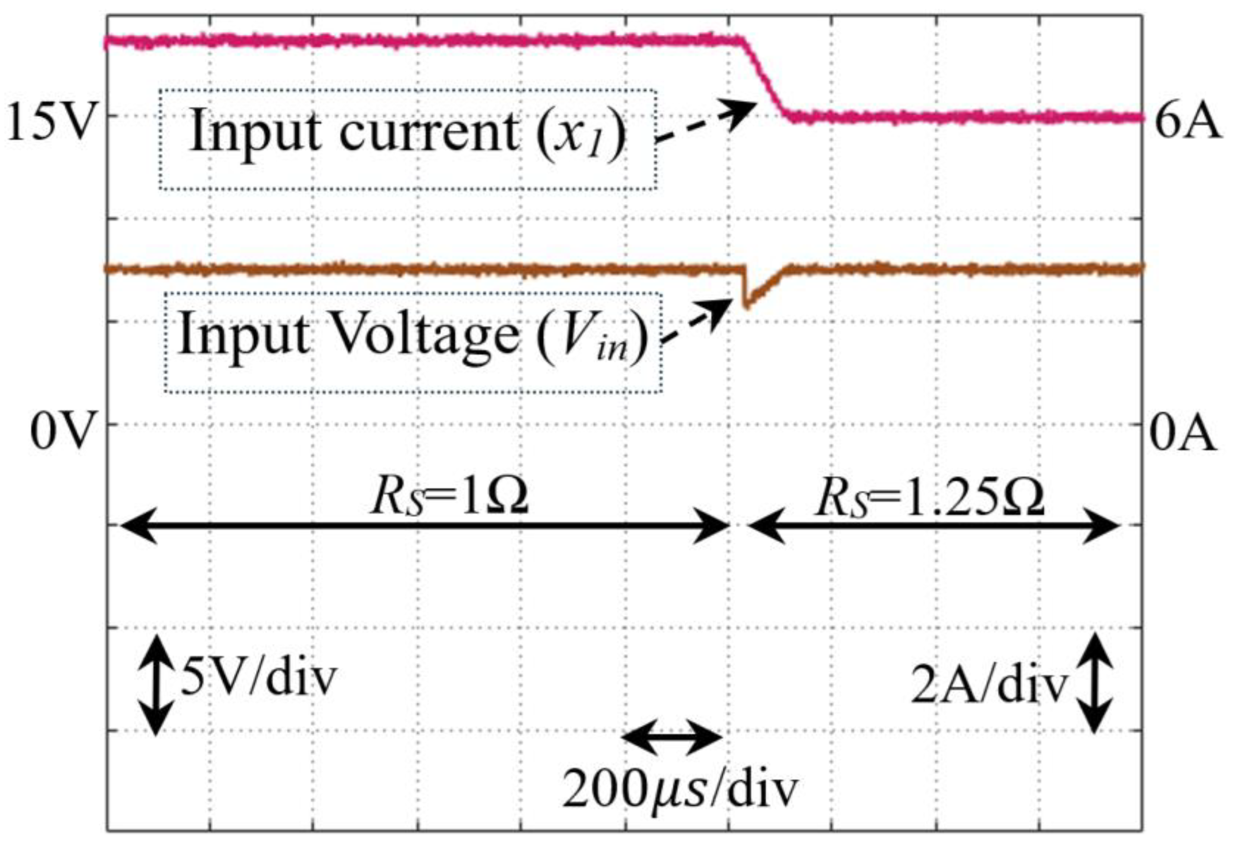

Table 1.
Nominal parameter values of the simulated system and experimental setup.
| Parameter | Symbol | Value |
| Open-Circuit Voltage | VS | 10V |
| Internal Resistance | RS | 1Ω |
| Load Voltage | VB | 24V |
| Converter Inductance | L | 1mH |
| Switching Frequency | fS | 100kHz |
Disclaimer/Publisher’s Note: The statements, opinions and data contained in all publications are solely those of the individual author(s) and contributor(s) and not of MDPI and/or the editor(s). MDPI and/or the editor(s) disclaim responsibility for any injury to people or property resulting from any ideas, methods, instructions or products referred to in the content. |
© 2025 by the authors. Licensee MDPI, Basel, Switzerland. This article is an open access article distributed under the terms and conditions of the Creative Commons Attribution (CC BY) license (http://creativecommons.org/licenses/by/4.0/).
Copyright: This open access article is published under a Creative Commons CC BY 4.0 license, which permit the free download, distribution, and reuse, provided that the author and preprint are cited in any reuse.


