
Submitted:
04 April 2025
Posted:
04 April 2025
You are already at the latest version
Abstract
To meet diverse industrial needs, temperature sensors with a wide measurement range have become an indispensable key element. In this paper, we propose an asymmetric Mach-Zehnder Interferometer (MZI) temperature sensor based on polymer optical waveguides. Experimental results show that the output interference signal exhibits periodic changes with temperature variations. The device exhibits a temperature measurement range of 120°C, and the sensitivity of 0.27 rad/°C. This study provides an effective new approach for developing high-performance, low-cost temperature sensors suitable for extended temperature measurement range.
Keywords:
Temperature sensor
; MZI
; Polymer
; Phase shift
1. Introduction
Integrated optical waveguides have demonstrated distinct advantages in the field of temperature sensing due to their miniaturization, high integration density, excellent stability, immunity to electromagnetic interference, low power consumption, and scalability [1,2,3,4]. Commonly employed structures encompass Mach-Zehnder interferometer (MZI) [5], grating structures [6], ring resonators [7], slot waveguides [8], and surface plasmon resonance structures [15]. Among these, the MZI has been extensively utilized in temperature sensing [12,13,14], due to its simple configuration [9], ease of integration [10], excellent stability [11], and broad material compatibility.
Temperature sensors based on MZI waveguides typically realize temperature sensing by measuring the phase difference between their upper and lower arms or the wavelength shifts caused by dispersion effects [16,17,18]. Lee et al. employed an MZI waveguide structure utilizing the opposite thermo-optic properties of SiO₂ and TiO₂, achieving a temperature sensitivity as high as 340 pm/°C within a measurement range of 25–35°C [19]. Ding et al. proposed a cascaded dual-MZI configuration based on silicon waveguide chips, leveraging the Vernier effect for phase-superposition amplification, thereby significantly enhancing temperature change response and attaining a sensitivity of 1753.7 pm/°C within a range of 27–67°C [20]. Payne et al. introduced an MZI structure with heterogeneous integration of silicon and silicon nitride, exploiting the substantial thermo-optic coefficient difference between these materials to achieve a sensitivity of 324 pm/°C in a measurement range of 9.7°C [21]. The aforementioned MZI-based temperature sensors predominantly utilize silicon material systems, capitalizing on silicon’s high thermo-optic coefficient to deliver superior sensitivity and high integration density [22]. However, in the ongoing search for optical waveguide materials with more diverse functionalities and broader application potential, polymer-based materials have been attracted attention [23,24,25,26].
Although polymeric materials are not yet employed as extensively as silicon, their ease of processing, low loss, and low cost have made them a research hotspot in waveguide materials, particularly well-suited for temperature sensor fabrication [27,28,29]. Moreover, polymers possess relatively high thermo-optic coefficients, effectively magnifying the optical signals induced by temperature changes and thereby significantly boosting sensor performance [30]. Niu et al. designed an asymmetric polymer waveguide MZI by introducing waveguides of different widths to accumulate the phase difference, thus enhancing temperature-sensing sensitivity. A sensitivity of 30.8 nm/°C was achieved over a measurement range of 25–28 °C [31]. Chen et al. employed two-photon polymerization (TPP) to fabricate an asymmetric polymer waveguide MZI structure. By introducing interferometer arms of distinct dimensions and packaging the device with a temperature-sensitive material, they enhanced the sensing sensitivity to approximately 2.01 nm/°C in the 30–70 °C range [32]. Guan et al. proposed an asymmetric MZI structure formed by hybridizing silicon waveguides with the SU-8 polymer, utilizing SU-8 as the waveguide core in one arm and exploiting the out-of-phase thermo-optic responses of SU-8 and silicon to achieve a sensitivity of 172 pm/°C within 20–45 °C [33]. Similarly, Gao et al. employed materials with opposing thermo-optic coefficients and introduced an asymmetric PMMA–SiO₂ hybrid waveguide MZI structure, achieving a sensitivity of 6.85 nm/°C within the 0–3 °C measurement range [34]. These temperature sensors, operating range of a few degrees up to several tens of degrees Celsius, exhibit high sensitivity and have laid a solid foundation for the development of polymer-based waveguide temperature sensors.
In this paper, an asymmetric MZI structure based on polymer waveguides was designed to achieve both high sensitivity and a broad measurement range for temperature sensing. By exploiting the high thermo-optic coefficient of polymeric materials and the length disparity between the two arms, the phase shift efficiency was effectively enhanced, thereby significantly improving sensor sensitivity. Moreover, because the primary measurement parameter is the temperature-dependent phase shift, the sensor offers a comparatively wide measurement range without the need for costly optical spectrum analyzer, markedly reducing overall costs and demonstrating substantial potential for practical applications.
2. Operating Principle and Device Design
The structure of proposed temperature sensor based on polymer waveguides is shown in Figure 1. The upper arm (Arm 1) is composed of two identical S-bend waveguides, whose total length depends on the S-bend offset and length. In contrast, Arm 2 is a straight waveguide with length , creating an optical path length difference () between the two arms. This difference creates the conditions for a phase shift between the two arms induced by ambient temperature changes. When a TE-polarized mode is launched, the Y-branch splits the incident light equally into both arms, each traveling a distinct optical path. As a result, the temperature-dependent phase variation caused by the optical path length difference leads to periodic interference signals in the output light signal.
During the temperature measurement process, the refractive indices of all material layers are influenced by the surrounding temperature. This dependency can typically be described using a linear model, as presented in Equation (1):
In the above equation, and represent the refractive indices at the initial temperature and after a temperature change, respectively. The parameter is the thermal optic coefficient (TOC), and denotes the temperature variation. A change in temperature directly influences the refractive indices of the waveguide layers, resulting in a corresponding shift in the effective refractive index. Because each layer’s refractive index varies linearly with temperature, the effective refractive index also exhibits an approximately linear response.
In an asymmetric MZI structure, when the temperature changes by , the phase difference between the two arms is mainly governed by the length mismatch and the change in effective refractive index. Its expression is given by:
In the above expression, denotes the change in effective refractive index due to the temperature variation . The parameter is the thermal expansion coefficient, and are the lengths of the upper and lower MZI arms, respectively, and is the operating wavelength. The sensor’s temperature sensitivity is defined as the rate of change of the phase difference with respect to temperature :
In Equation (3), because the silicon substrate serves as a rigid carrier with an extremely low thermal expansion coefficient (approximately 2 ppm/°C) and a high elastic modulus, it provides robust in-plane confinement for the spin-coated polymer layer. Although the chosen polymer exhibits a relatively large thermal expansion coefficient (around 350 ppm/°C), its inherent tendency to expand freely when heated is strongly suppressed in-plane, leading primarily to the accumulation of internal stress rather than any significant dimensional change. As a result, the phase variation caused by thermal expansion is substantially smaller than that induced by the thermo-optic effect (i.e., refractive index change). Hence, the length-change term can be neglected (i.e., 。), and the temperature sensitivity can be simplified to:
To fabricate the asymmetric MZI temperature sensor, ZPU and LFR polymer materials from Chemoptics Co., Ltd. with refractive indices of 1.43 and 1.395 at 1550 nm were employed for the core and cladding layers, respectively. To generate an optical path length difference between the upper and lower arms of the MZI, two S-bend structures are adopted in one of the arms. Moreover, simulation analysis is carried out using Rsoft software, and the losses caused by the offset and length of the S-bends are calculated, as shown in Figure 2. The length difference ΔL between the upper and lower arm is determined by different parameter configurations, which is represented by the black contour lines in the figure. When light passes through the S-bend structure, it will undergo varying degrees of attenuation. Different colors in the figure correspond to different attenuation intervals. Balancing low loss and desired temperature sensitivity, a path difference of 300 µm was selected for the experiments, with an S-bend offset of 1750 µm and an S-bend length of 12500 µm. Under these conditions, the insertion loss remains below −1 dB.
3. Fabrication of the Integrated Optic Temperature Sensor
The proposed polymer waveguide-based integrated optical temperature sensor was fabricated using ZPU143 and LFR1395 materials from Chemoptics Co., Ltd. through planar lightwave circuit (PLC) technology. The fabrication procedure is schematically presented in Figure 3. A lower cladding layer of LFR1395 with a thickness of 10 μm was formed on a silicon wafer by spin-coating and UV curing. After coating a photoresist layer on the LFR1395 layer and a core waveguide pattern was formed through a photolithography process and oxygen plasma etching. The cladding layer was etched 1.45 μm to satisfy single mode waveguide. Then, 4.1 μm of ZPU143 was coated over the etched cladding layer as a core layer. A cladding of LFR1395 was coated and cured, and then Cr–Au was deposited to form a micro-heater with a width of 40 μm through a second photolithography process and wet etching to finish the device.
4. Characterization of the Fabricated Device
Before measuring the performance of the temperature sensor, to ensure that the MZI has effective interference performance, devices such as a DFB laser, a polarization controller, a function signal generator, and an optical power meter were used for testing and the measurement setup is shown in Figure 4(a). By applying a triangular voltage waveform to the electrode on one of the MZI arms, causing the refractive index of the polymer material to decrease and creating a phase difference between the two arms, that produces the output interference signal, as shown in Figure 4(b). It can be observed that the interference signal exhibits obvious periodic variations, and the extinction ratio of the signal can reach over 10 dB, thus verifying the interference characteristics of the device.
To measure the characteristics of the fabricated temperature sensor, devices such as a DFB laser, a polarization controller, hotplate with a heating chamber, temperature collector, and an optical power meter were used, and the measurement setup is shown in Figure 5 (a). The sensor was placed inside a partially sealed heating chamber, with a PT100 temperature probe affixed to the sensor surface to monitor its temperature. The input polarization was adjusted to the TE mode. During measurement, the chamber temperature was increased from 38°C to 158°C, while the surface temperature and output optical power were recorded at 2°C intervals using the PT100 probe and an optical power meter, respectively. When the temperature changes, a phase difference is generated between the upper and lower arms of the sensor, resulting in an interference signal at the output port. Thus, the relationship between the optical power and the temperature can be obtained, as shown in Figure 5 (b). From temperature dependent optical output power (Blue dot) in Figure 5(b), it can be observed that the output power exhibits an exponentially decreasing sinusoidal variation with increasing temperature, although some signal attenuation occurs. This is largely attributable to the substantial loss introduced by the S-bend in the MZI structure. The light emerging from the waveguide transitions into planar waveguide modes and interferes at the output. Moreover, at elevated temperatures, the expansion of the UV adhesive between the fiber array and the sensor facet reduces coupling efficiency. By fitting the measured optical intensity data and extracting the sinusoidal component (as shown by the red curve in Figure 5(b)), the phase change induced by temperature can be derived. A temperature sensitivity of 0.27 rad/°C was obtained, as presented in Figure 5(c).
Table 1 compares the results of this work with those of recent publications on silicon and polymer waveguide-based asymmetric MZI temperature sensors. The comparison covers materials, device structure, sensitivity, sensing range, and measurement metric. Compared with references [31,32,33,34], the measurement metric differs, which prevents a direct performance comparison. However, the measurable range clearly shows that our device performs significantly better than the others. In comparison with references [35], although non-polymer materials were used, the device structure remains identical and the measurement metric is based on phase change. However, it can only achieve a detection range of up to 40°C. The table demonstrates that our results offer both higher sensitivity and a broader measurement range. In comparison, this work utilizes LFR and ZPU series polymer materials, achieving a significantly wide measurement range of 120°C and excellent sensitivity of 0.27 rad/°C with an arm length difference of only 300 µm.
6. Conclusion
An asymmetric MZI temperature sensor based on polymer optical waveguides was demonstrated. To achieve low loss and high phase shift, the length difference L between the two arms of the MZI is set to 300 µm. When the TE mode is input, light is split evenly into the upper and lower arms through a Y-branch and experiences different optical paths. The temperature-related phase changes caused by the optical path difference induce periodic interference signals in the output light. Although the output power exhibits a sinusoidal variation with increasing temperature, signal attenuation is observed. This is due to the significant loss of the S-bend in the MZI structure, and the light that emerges from the waveguide forms a plane waveguide mode, generating interference signals at the output end. Additionally, high temperatures cause the UV adhesive between the fiber array end and the temperature sensor end to expand, reducing the coupling efficiency. As a result, when the measurement range exceeds 120°C, the interference signal disappears. By fitting the optical intensity signals collected within the 120°C range and extracting the sinusoidal components, phase changes were calculated based on the extracted sinusoidal signal. This yields a temperature sensitivity of 0.27 rad/°C.
Author Contributions
Conceptualization, F. L. and G. H.; methodology, F. L. and G. H.; Simulation, X. Z. and T. W.; Writing original draft preparation, F. L.; Writing—review and editing, F. L. and G. H.; All authors have read and agreed to the published version of the manuscript.
Funding
This work was supported by National Key Research and Development Project (Grant No. 2020YFB1313604).
Institutional Review Board Statement
The authors declare no conflicts of interest.
Data Availability Statement
The original contributions presented in the study are included in the article. Further inquiries can be directed to the corresponding author.
Conflicts of Interest
The authors declare no conflicts of interest
References
- Jiao, H.; Qing, C.; Li, X.; Sun, D.; Wang, L.; Zhou, Y.; Wang, K.; Feng, L. Hybrid Integrated Optical Transceiver for Interferometric Fiber-Optic Sensors. IEEE Sens. J. 2024, 24, 10188–10195. [CrossRef]
- Yao, N.; Wang, S. Recent Progress of Optical Tactile Sensors: A Review. Opt. Laser Technol. 2024, 176, 111040. [CrossRef]
- Lu, Q.; Wang, Y.; Wang, X.; Yao, Y.; Wang, X.; Huang, W. Review of Micromachined Optical Accelerometers: From Mg to Sub-Μg. Opto-Electron. Adv. 2021, 4, 200045-1–200045–24. [CrossRef]
- Zhou, J.; Wang, Y.; Zhang, G.-J. State-of-the-Art Strategies of Surface Plasmon Resonance Biosensors in Clinical Analysis: A Comprehensive Review. Coord. Chem. Rev. 2024, 520, 216149. [CrossRef]
- Bruck, R.; Melnik, E.; Muellner, P.; Hainberger, R.; Lämmerhofer, M. Integrated Polymer-Based Mach-Zehnder Interferometer Label-Free Streptavidin Biosensor Compatible with Injection Molding. Biosens. Bioelectron 2011, 26, 3832–3837. [CrossRef]
- Chen, J.; Liu, B.; Zhang, H. Review of Fiber Bragg Grating Sensor Technology. Front. Optoelectron 2011, 4, 204–212. [CrossRef]
- Zhang, Z.; Wang, Y.; Wang, J.; Yi, D.; Chan, D.W.U.; Yuan, W.; Tsang, H.K. Integrated Scanning Spectrometer with a Tunable Micro-Ring Resonator and an Arrayed Waveguide Grating. Photon. Res. 2022, 10, A74–A81. [CrossRef]
- Wang, Y.; Zhong, L.; Lau, K.Y.; Han, X.; Yang, Y.; Hu, J.; Firstov, S.; Chen, Z.; Ma, Z.; Tong, L. Precise Mode Control of Laser-Written Waveguides for Broadband, Low-Dispersion 3D Integrated Optics. Light Sci. Appl. 2024, 13, 130. [CrossRef]
- Su, H.; Zhao, C.; Song, X.; Kong, F.; Zhang, Z.; Liu, C. High-Sensitivity Optical Fiber Temperature Sensor with Cascaded Configuration of MZI and FPI Based on Vernier Effect. Opt. Fiber Technol. 2021, 67, 102751. [CrossRef]
- Peng, C.; Yang, C.; Zhao, H.; Liang, L.; Zheng, C.; Chen, C.; Qin, L.; Tang, H. Optical Waveguide Refractive Index Sensor for Biochemical Sensing. Appl. Sci. 2023, 13, 3829. [CrossRef]
- Han, J.; Wu, X.; Ge, X.; Xie, Y.; Song, G.; Liu, L.; Yi, Y. Highly Sensitive Liquid M-Z Waveguide Sensor Based on Polymer Suspended Slot Waveguide Structure. Polymers 2022, 14, 3967. [CrossRef]
- El Shamy, R.S.; Khalil, D.; Swillam, M.A. Mid Infrared Optical Gas Sensor Using Plasmonic Mach-Zehnder Interferometer. Sci. Rep. 2020, 10, 1293. [CrossRef]
- Xiong, C.; Liao, C.; Li, Z.; Yang, K.; Zhu, M.; Zhao, Y.; Wang, Y. Optical Fiber Integrated Functional Micro-/Nanostructure Induced by Two-Photon Polymerization. Front. Mater. 2020, 7, 586496. [CrossRef]
- Chatzianagnostou, E.; Manolis, A.; Dabos, G.; Ketzaki, D.; Miliou, A.; Pleros, N.; Markey, L.; Weeber, J.-C.; Dereux, A.; Chmielak, B.; et al. Scaling the Sensitivity of Integrated Plasmo-Photonic Interferometric Sensors. ACS Photonics 2019, 6, 1664–1673. [CrossRef]
- Wang, Q.; Ren, Z.-H.; Zhao, W.-M.; Wang, L.; Yan, X.; Zhu, A.; Qiu, F.; Zhang, K.-K. Research Advances on Surface Plasmon Resonance Biosensors. Nanoscale 2022, 14, 564–591. [CrossRef]
- Zhao, C.; Xu, L.; Liu, L. Ultrahigh Sensitivity Mach-Zehnder Interferometer Sensor Based on a Weak One-Dimensional Field Confinement Silica Waveguide. Sensors 2021, 21, 6600. [CrossRef]
- Ma, Y.; Nghia, N.-H.; Zhou, J.; Maeda, H.; Wu, Q.; Eldlio, M.; Pistora, J.; Cada, M. Mach-Zehnder Interferometer-Based Integrated Terahertz Temperature Sensor. IEEE J. Sel. Top. Quantum Electron 2017, 23, 4601607. [CrossRef]
- Guo, J.; Yang, C.; Dai, Q.; Kong, L. Soft and Stretchable Polymeric Optical Waveguide-Based Sensors for Wearable and Biomedical Applications. Sensors 2019, 19, 3771. [CrossRef]
- Lee, J.-M. Ultrahigh Temperature-Sensitive Silicon MZI with Titania Cladding. Front. Mater. 2015, 2, 36. [CrossRef]
- Ding, Z.; Dai, D.; Shi, Y. Ultra-Sensitive Silicon Temperature Sensor Based on Cascaded Mach–Zehnder Interferometers. Opt. Lett. 2021, 46, 2787–2790. [CrossRef]
- Payne, D.A.; Matthews, J.C. A CMOS-Compatible Heterogeneous Interferometer for Chip-Scale Temperature Sensing. Appl. Phys. Lett. 2022, 121. [CrossRef]
- Zegadi, R.; Ziet, L.; Zegadi, A. Design of High Sensitive Temperature Sensor Based on Two-Dimensional Photonic Crystal. Silicon 2020, 12, 2133–2139. [CrossRef]
- Liu, J.; Zhang, Z. Polymer-Embedding Germanium Nanostrip Waveguide of High Polarization Extinction. Polymers 2023, 15, 4093. [CrossRef]
- Xie, Y.; Chen, L.; Li, H.; Yi, Y. Polymer and Hybrid Optical Devices Manipulated by the Thermo-Optic Effect. Polymers 2023, 15, 3721. [CrossRef]
- Pudleiner, T.; Hoinkis, J.; Karnutsch, C. Analysis of Diffracted Mode Outcoupling in the Context of Amplified Spontaneous Emission of Organic Thin Films. Polymers 2024, 16, 1950. [CrossRef]
- Pascault, J.-P.; Williams, R.J. Thermosetting Polymers. Handb. Polym. Synth. Charact. Process. 2013, 519–533.
- Leal-Junior, A.; Frizera-Neto, A.; Marques, C.; Pontes, M.J. A Polymer Optical Fiber Temperature Sensor Based on Material Features. Sensors 2018, 18, 301. [CrossRef]
- Mieloszyk, M.; Majewska, K.; Andrearczyk, A. Embedded Optical Fibre with Fibre Bragg Grating Influence on Additive Manufactured Polymeric Structure Durability. Materials 2022, 15, 2653. [CrossRef]
- Lakard, B.; Carquigny, S.; Segut, O.; Patois, T.; Lakard, S. Gas Sensors Based on Electrodeposited Polymers. Metals 2015, 5, 1371–1386. [CrossRef]
- Oh, M.-C.; Chu, W.-S.; Shin, J.-S.; Kim, J.-W.; Kim, K.-J.; Seo, J.-K.; Lee, H.-K.; Noh, Y.-O.; Lee, H.-J. Polymeric Optical Waveguide Devices Exploiting Special Properties of Polymer Materials. Opt. Commun. 2016, 362, 3–12. [CrossRef]
- Niu, D.; Wang, L.; Xu, Q.; Jiang, M.; Wang, X.; Sun, X.; Wang, F.; Zhang, D. Ultra-Sensitive Polymeric Waveguide Temperature Sensor Based on Asymmetric Mach–Zehnder Interferometer. Appl. Opt. 2019, 58, 1276–1280. [CrossRef]
- Chen, M.-Q.; Lin, Z.-Y.; Zhao, Y. Femtosecond Laser Direct-Writing On-Chip MZI Temperature Sensor Based on Polymer Waveguides. IEEE Trans. Instrum. Meas. 2023, 72, 1–8. [CrossRef]
- Guan, X.; Wang, X.; Frandsen, L.H. Optical Temperature Sensor with Enhanced Sensitivity by Employing Hybrid Waveguides in a Silicon Mach-Zehnder Interferometer. Opt. Express 2016, 24, 16349–16356. [CrossRef]
- Gao, Z.; Du, Y.; Zhang, Q.; Qin, Y.; Fang, J.; Yi, Y. Silica–Polymer Heterogeneous Hybrid Integrated Mach–Zehnder Interferometer Optical Waveguide Temperature Sensor. Polymers 2024, 16, 2297. [CrossRef]
- Li, G.; Li, T.; Liu, Y.; Zheng, Y. A New Mach–Zehnder Interference Temperature Measuring Sensor Based on Silica-Based Chip. Sci. Rep. 2024, 14, 8657. [CrossRef]
Figure 1.
Schematic diagram of the asymmetric MZI-based temperature sensor employing polymer waveguides.
Figure 1.
Schematic diagram of the asymmetric MZI-based temperature sensor employing polymer waveguides.
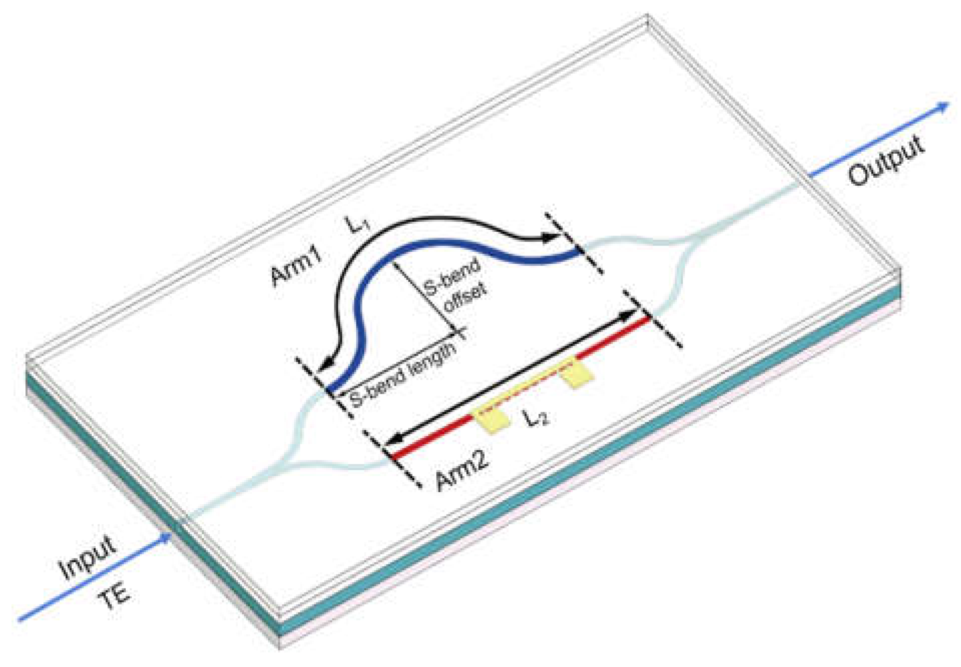
Figure 2.
Distribution of optical loss in the S-bend waveguide structure as a function of different S-bend offset and length. Black line depicts length difference (ΔL) between two arms of MZI.
Figure 2.
Distribution of optical loss in the S-bend waveguide structure as a function of different S-bend offset and length. Black line depicts length difference (ΔL) between two arms of MZI.
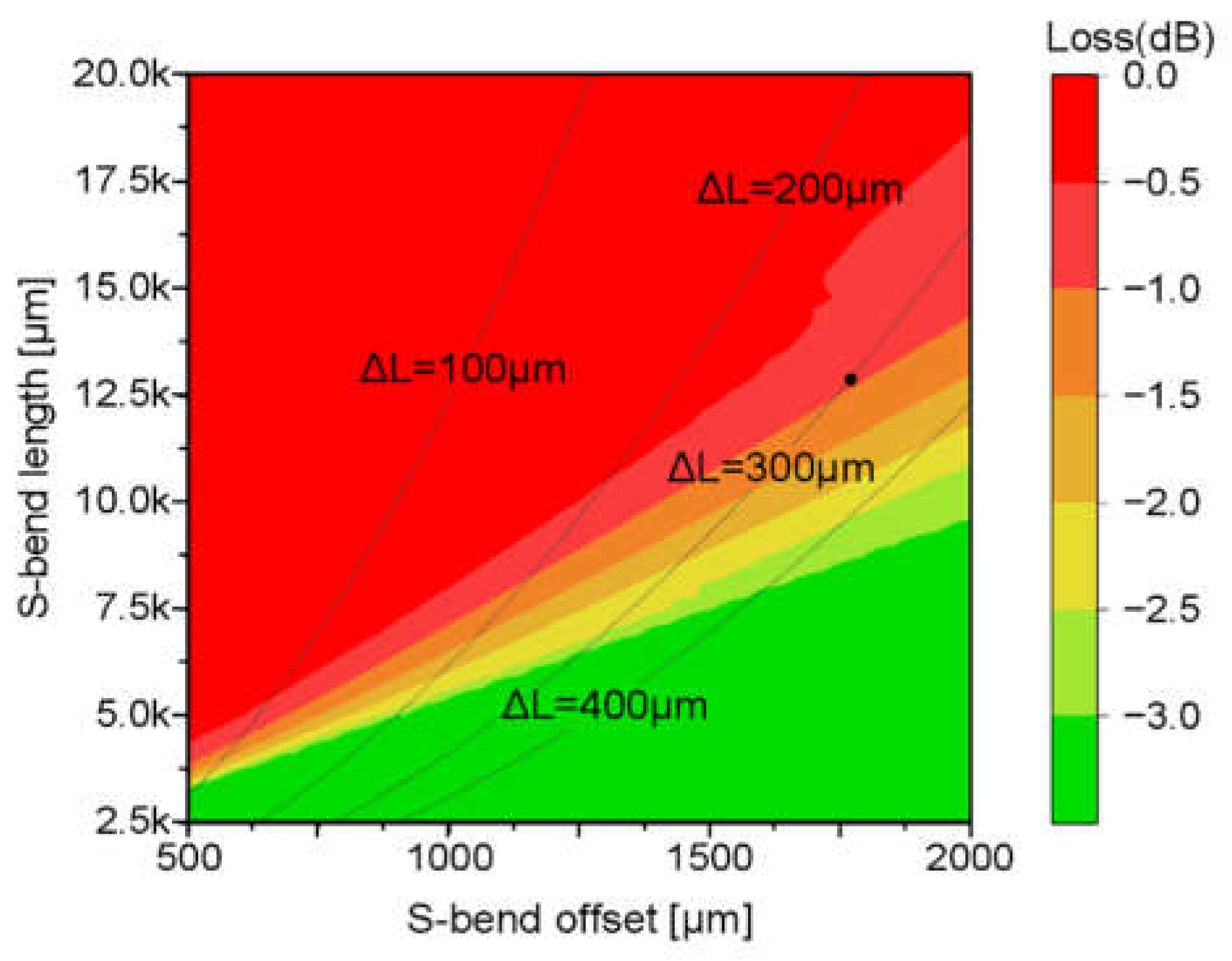
Figure 3.
Fabrication process of the asymmetric MZI waveguide temperature sensor.
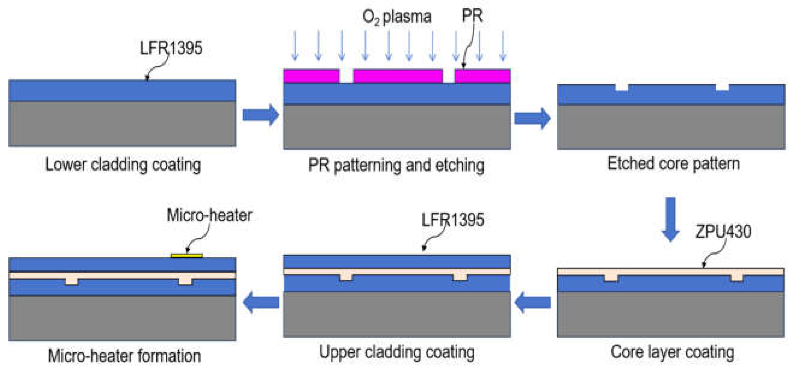
Figure 4.
(a) Measurement setup for interference performance test of MZI. (b) Optical interference signals measured by applying a triangular voltage waveform to the electrode on one of the MZI arms.
Figure 4.
(a) Measurement setup for interference performance test of MZI. (b) Optical interference signals measured by applying a triangular voltage waveform to the electrode on one of the MZI arms.
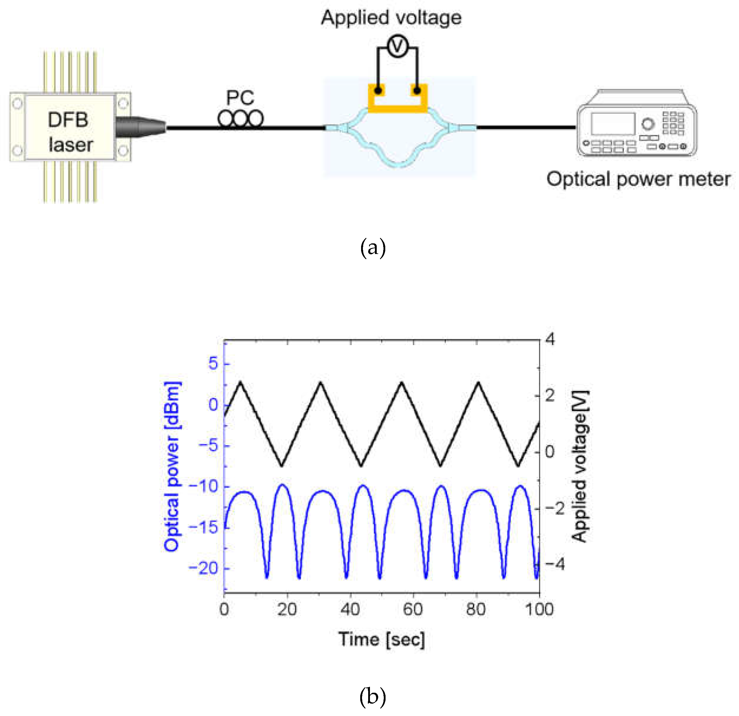
Figure 5.
(a) Experimental setup for measuring the temperature response of the sensor. (b) Temperature dependent optical output power as a function of exponentially decreasing sine signal (Blue dot). A sinusoidal signal (Red line) extracted from the fitted curve (Blue line). (c) Phase variation obtained from the extracted sinusoidal signal as a function of temperature change.
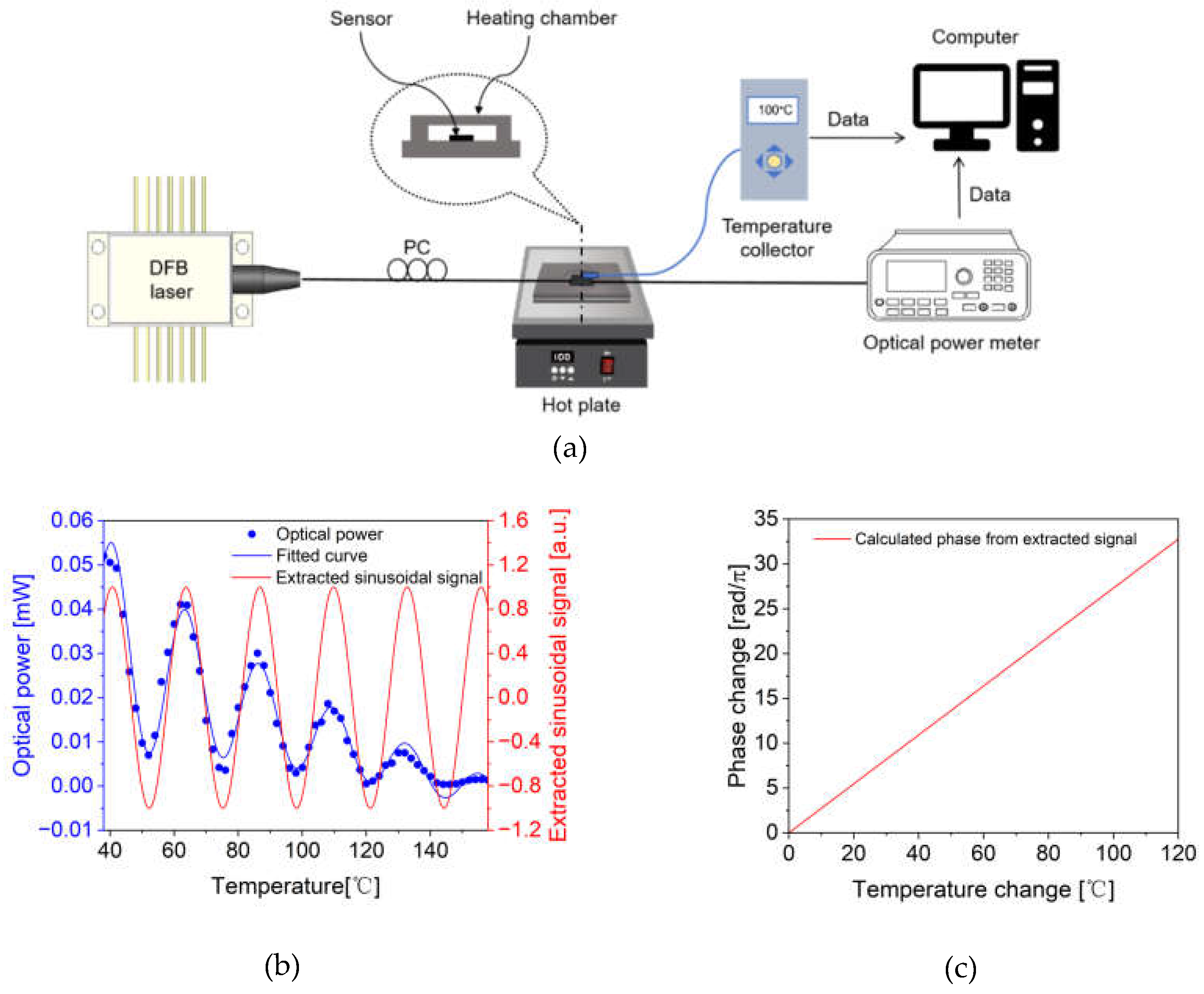

Table 1.
Comparison of temperature sensors based on silicon and polymer materials.
| Ref. | Materials | Year | Structure | Sensitivity (rad/°C or pm / °C) |
Sensing Range(°C) | Measurement Metric |
|---|---|---|---|---|---|---|
| [31] | NOA, M-2000 | 2019 | Asymmetric MZI |
30800 pm/°C | 3 | Wavelength |
| [32] | IP-S, PDMS | 2023 | Asymmetric MZI |
20100 pm/°C | 40 | Wavelength |
| [33] | Silicon, SU-8 | 2016 | Asymmetric MZI |
172 pm/°C | 25 | Wavelength |
| [34] | PMMA, NOA SU-8 |
2024 | Asymmetric MZI |
6860 pm/°C | 3 | Wavelength |
| [35] | Silicon, SiO₂ | 2024 | Asymmetric MZI |
0.0785 rad/ °C | 40 | Phase |
| This work | LFR, ZPU | 2025 | Asymmetric MZI |
0.27 rad/ °C | 120 | Phase |
Disclaimer/Publisher’s Note: The statements, opinions and data contained in all publications are solely those of the individual author(s) and contributor(s) and not of MDPI and/or the editor(s). MDPI and/or the editor(s) disclaim responsibility for any injury to people or property resulting from any ideas, methods, instructions or products referred to in the content. |
© 2025 by the authors. Licensee MDPI, Basel, Switzerland. This article is an open access article distributed under the terms and conditions of the Creative Commons Attribution (CC BY) license (http://creativecommons.org/licenses/by/4.0/).
Copyright: This open access article is published under a Creative Commons CC BY 4.0 license, which permit the free download, distribution, and reuse, provided that the author and preprint are cited in any reuse.


