
Submitted:
07 April 2025
Posted:
10 April 2025
You are already at the latest version
Abstract
The future fusion power plant EU DEMO will generate its own tritium fuel through the use of segmented breeding blankets (BBs), which must be replaced from time to time due to material damage caused by high-energy neutrons from the plasma. A vertical maintenance architecture has been proposed, using a robotic remote handling tool (transporter) to disengage the 125t and 180t outboard and inboard segments and manipulate them through an upper port. Safe disengagement without damaging the support structures requires the use of high-capacity tilting joints in the transporter. The trolley tilting mechanism (TTM) is proposed as a novel, compact, high-capacity robotic joint consisting of a 5-bar spatial mechanism integrated in the BB transporter trolley link. A kinematic model of the TTM is established, and the analytical input-output relationships, including position-dependent transmission ratio, are derived and used to guide the design and optimization of the mechanism. The model predictions are compared to an ADAMS multibody simulation, and to the results of an experiment conducted on a down-scaled prototype, both of which validate the model accuracy.
Keywords:
Kinematics
; 5-bar spatial mechanism
; Robotic manipulator
; Breeding Blanket
; Remote maintenance
1. Introduction
The development of fusion energy technology could lead to the deployment of high-output, carbon-free tokamak reactors in the future. ITER, the world’s largest experimental tokamak, is currently under construction and the European successor, EU DEMO, is now being designed with the aim of demonstrating the technical and economic readiness of fusion energy while providing net electricity to the grid [1]. In addition to being larger and experiencing greater heat and mechanical loads than ITER, the DEMO tokamak (Figure 1a) will also integrate a self-sufficient tritium lifecycle based on breeding blankets (BBs) lining the inner vacuum vessel [2]. The BBs will be the largest and heaviest in-vessel components, and will require occasioreplacement due to material degradation from neutron irradiation. It is a requirement that this remote maintenance task be carried out safely while minimizing down-time of the plant [3].
Unlike ITER, European DEMO will use a vertical maintenance architecture for the BBs, which has also been considered for earlier tokamaks including INTOR [4]. This entails the maintenance of three 180 t outboard and two 125 t BB segments within each of the 16 tokamak sectors using a mobile cask which docks to a sector’s upper port and contains the necessary remote handling (RH) equipment to remove or replace a BB segment. This concept is illustrated in Figure 1b, depicting a robotic RH tool vertically transporting a BB segment within the confines of the vacuum vessel, upper port, and cask. This tool is the BB vertical transporter (BBVT), which was previously introduced in [5,6]. With minimal simplifications, the BBVT can be considered a redundant serial robotic manipulator with 7 degrees of freedom, enabling full spatial motion of the end effector.
Attachment and support structures for the BB segments, seen in Figure 2a, were introduced in [9] and further developed in [8,10]. These include radial, vertical and toroidal support structures which react against different loading conditions of the BB segments during operation of the tokamak. When the tokamak is powered down, as during maintenance, each BB segment is vertically supported only at the bottom and can be lifted by a countersunk interface in the portion of the top surface exposed in the port [11]. A short vertical translation and toroidal tilt are required to free each BB segment from its lower supports.
Besides the vertical load, the BBVT is also subject to large moments [12]. This is due to the fact that the countersunk interface by which each BB segment is grasped is horizontally offset from the center of mass to be accessible by the BBVT inside the upper port. However, rather than being automatically reacted by the BBVT when initially loading a BB segment for lifting, these moments are primarily reacted by the radial and toroidal BB segment supports. This is a problem, as these loads could damage the supports as the contact surface areas shrink during disengagement. This is of particular concern for the toroidal shear keys. Thus, these horizontal moment components must be actively counteracted by the BBVT to avoid loading the supports during disengagement, as illustrated in Figure 2b.
As can be seen in the schematic diagram Figure 3, the BBVT has two tilting joints: the distal gripper tilting joint, and the centrally located trolley tilting joint. The former is required for tilting the BB segments toroidally up to 8∘ during handling to avoid collisions, while the latter is necessary for tilting the gripper radially by approximately 0.5∘ to 1.5∘ in order to ensure proper alignment of the gripper interface before and during engagement. Due to the need to counteract the reaction forces in the BB segment supports during initial lifting, both tilting joints are required to actively apply the equivalent off-center lifting moments to the BB segment. Space is also at a premium, as the BBVT must fit and maneuver within the constricted upper port.
A five bar mechanism, referred to as the trolley tilting mechanism or TTM, is proposed and designed in this work to address this unique set of challenges. A kinematic model of the linkage is established and applied to analyze and optimze the design, and numerical simulations and simulations and experiments are performed to validate the design and the kinematic model.
The current work is divided into 6 sections. In Section 2, Mechanism Design: the design requirements and considerations for the TTM are detailed, and the current design is presented. In Section 3, Kinematics: the kinematic constraint equations for the TTM are derived and an analytical solution for the forward kinematics is presented, along with the configuration-dependent transmission ratio and mechani. In Section 4, Mechanical Design Optimization: the kinematic model is used as a basis to optimize two of the bar lengths with respect to range of motion as well as maximum static loads on the mechanism output and input during BB segment maintenance. In Section 5, Verification and Preliminary Down-scaled Experiment: the kinematic model is verified by comparison with a numerical simulation in ADAMS, and further validated by initial experiments on a down-scaled TTM prototype. Finally, in Section 6, Discussion and Conclusion: the results and contributions are discussed, and limitations and future work presented.
2. Mechanism Design
The main requirement for the TTM is to provide the ability to adjust the radial tilt of the gripper by a small angle (about 0.5 to 1.5) in order to align it during engagement with the BB segment countersunk interface. In terms of carrying capacity, the TTM must have the ability to “preload” the 180 t outboard and 125 t inboard lateral BB segments with a radial moment to counter the formation of reactions within the support structures during lifting. To match the other BBVT joints, the TTM should be implemented using standard electrical actuators rather than hydraulics.
As indicated in Figure 3, the TTM is placed as the fourth joint of the BBVT, between the links referred to as the trolley and the trunk. The reason for this is that the space adjacent to the gripper itself is taken by the gripper tilting joint, and the trolley is the next-closest link with available space. However, even here the horizontal space is limited as the trolley (essentially a box) must fit within the constricted upper port while the BBVT is engaged with each of the 5 BB segments. As the trolley slides on a large radial rail, the radial faces are nearly inaccessible. Also, the lower vertical face is largely occupied by the trunk connection. Thus, the only practical location for the TTM actuator(s) is on the upper face, and the output radial motion must be applied to a tilting plate sitting between the trolley and trunk. The problem, then, is to connect the actuator(s) and tilting plate while affecting the toroidal and radial dimensions of the trolley assembly minimally. This combination of requirements and restrictions is difficult to solve compactly and reliably using only conventional transmission elements such as gearboxes, belts, chains, or screws.
Thus, a compact 5-bar mechanism providing good mechanical advantage was designed, shown in Figure 4a. It is a spatial linkage with structure RSRRR, where “R” denotes a revolute joint and “S” denotes a spherical joint, with Grübler criterion equal to 1. The four mobile bars have been marked with their lengths a, b, c and d. The first (a) is the eccentricity of a cam connected to the input shaft. This is connected via a radial bearing with spherical housing to the rod b. At its lower end, the rod attaches to a short connector c, which connects the rod and the tilting plate d using pins at right angles. The plate connects back to the trolley at the tilting hinge, which constitutes the TTM output.
The use of the mechanism is similar to a planar four-bar mechanism, where mechanical advantage is gained by relative sizing of the bars connected to the input and output joints, while the connecting bars in between serve primarily to transfer the load. The mechanism wraps around the vertical and toroidal faces of the trolley, which is required in order to not interfere with the radial rail. However, a planar four-bar mechanism cannot wrap around in this manner while having good leverage and avoiding collision with the trolley itself. Instead, the input axis located above the trolley is made to be toroidal, perpendicular to the output axis. Then, an extra bar (c) is added to connect the radial output and toroidal input. The main connecting bar (b) then must be able to tilt both toroidally and radially due to the interconnected motion of the input and output bars, necessitating the use of a spherical connection between a and b, in this case chosen as a radial bearing with spherical housing. This configuration also gives space radially along the top surface of the trolley to place multiple tilting mechanisms in parallel to reduce the load on the input actuator(s).
3. Kinematics
Optimization and control of the TTM require an accurate kinematic model, which will be derived in this section. Although kinematic models of RSRRR 5-bar mechanisms exist, since the TTM is a special case, a model using only 5 relative rotation coordinates and 4 equations (compared with 15 equations in [13]) is derived based on the schematic diagram in Figure 4b. The coordinates are: , , , , and , where is the joint variable associated with the input of the mechanism and is associated with the output. The input shaft and output shaft angles are each defined as being zero when their respective bars (a and d) are horizontal. The following assumptions are made: the rotation axes of the joints and are pairwise perpendicular, and the rotation axes of the joints are all parallel.
With reference to the schematic (Figure 4b), the following four independent equations constrain the kinematics:
where are the constant coordinates of the mechanism output point relative to the input point. For simplicity, and to ensure that when , these will be assumed to take on the values , , and when the equations are applied throughout this work, although it is not strictly necessary. For example, in the case of replacing the input cam with one of different size without also adjusting and d, this would not hold.
3.1. Forward Kinematic Solution
By squaring and summing (2) and (3) and utilizing Equation (4), can be found:
Physically valid and non-extraneous solutions are obtained by only taking the positive solutions for (6) and (9).
Using Equation (4), can be eliminated from Equation (2) and Equation (3). The system of equations can then be solved for in terms of known and derived angles (, , and ) by taking advantage of the fact that a system of equations of the form
has the solution:
Thus,
To find , the solutions for and can be plugged into (4). Alternatively, the same procedure used to find can be applied, but using (4) to eliminate from (2) and (3). Also, rather than relying on (13), alternative forms of the solutions for and/or can be found using the tangent of the half-angle substitution method.
3.2. Transmission Ratio and Mechanical Advantage
The constraint equations (1) to (3) can be differentiated with respect to time to give the velocity constraints:
where is the vector of time derivatives of the coordinates and is the Jacobian matrix of the constraint equations:
The system of four equations in (15) can be solved to find the ratio of input and output speeds, or transmission ratio :
By the conservation of energy, and neglecting inertia and friction forces, the input power must equal the output power, leading to the assertion of the mechanical advantage provided by the mechanism:
where and are the torques at the input shaft and output hinge, respectively.
The factor in parentheses in (18) depends on the configuration of the mechanism as well as the chosen bar lengths. This is illustrated by Figure 5, where this factor g is plotted as a function of the input angle for several TTM designs. As can be seen, g is sensitive to a, b, or d but does not depend strongly on c. When , the mechanism is in a kinematic singularity where the output angle reverses direction, this generally occurs near and should be considered when controlling the mechanism.
3.3. Inverse Kinematics
Although an analytical solution of the kinematic equations for exists when is known, as described in Section 3.1 above, the inverse is not true. Instead, can be found numerically using the Newton-Raphson method with the constraint Jacobian (16) i.e. iteratively solving for an equation of the form:
where is the vector of constraint equations (1) to (3) evaluated at .
4. Mechanical Design Optimization
An initial sizing of the TTM based only on the space available and the geometry of the BBVT trolley has given m, m, m and m. However, it may be possible to optimize this using the kinematic model derived in Section 3. Two important properties of interest are the transmission ratio and range of motion of the mechanism.
In the home position, the transmission ratio (17) reduces to the simple ratio of the lengths of the output and input bars:
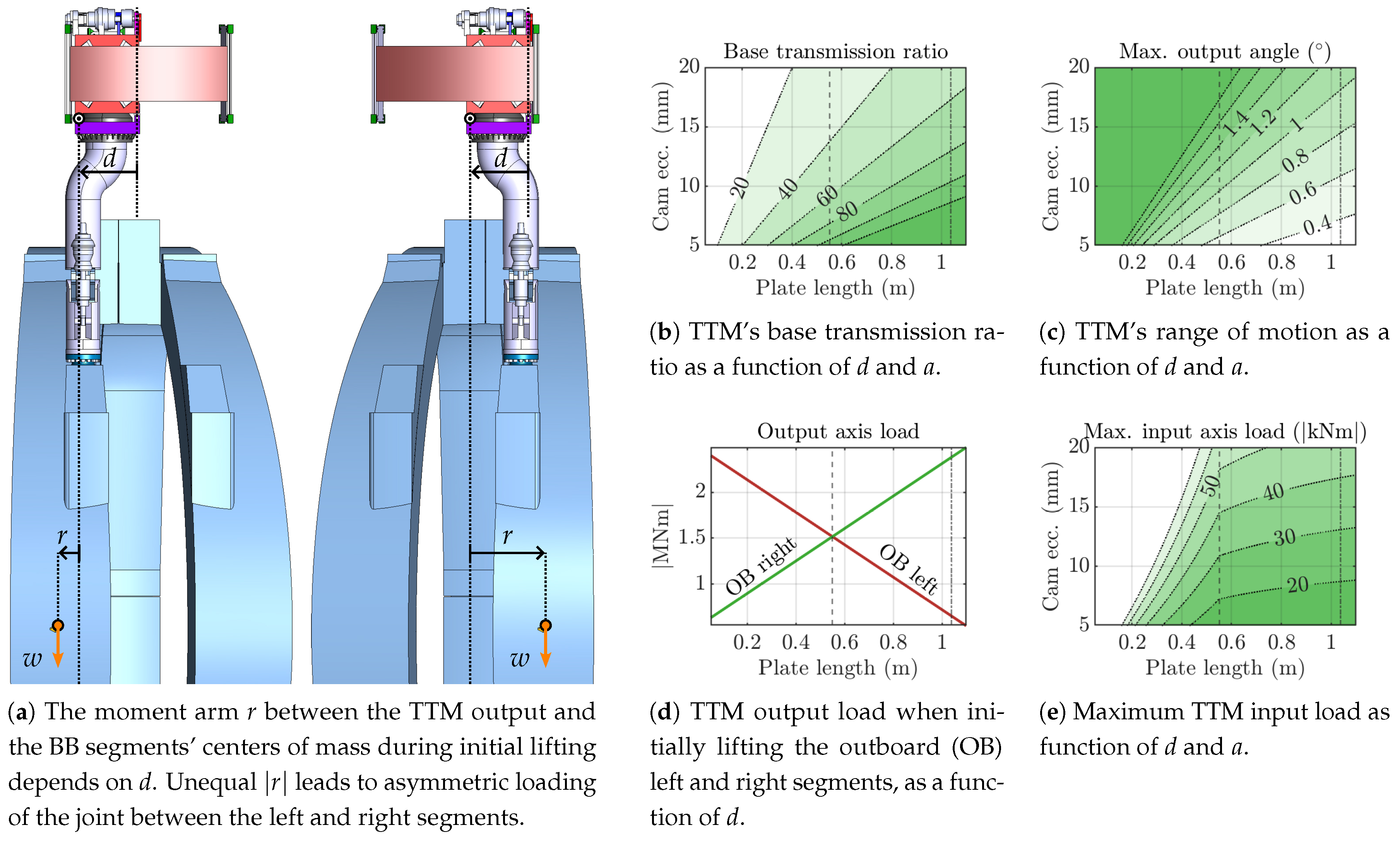
We will refer (20) as the base transmission ratio, as the true transmission ratio almost always increases in magnitude when the mechanism is not in home position, due to the geometry factor generally obeying for designs where and . In order to minimize the sizes of the required actuators and gearboxes, a base transmission ratio of about 50–100 is desired. Figure b plots expected values of for relevant ranges of a and d based on (20), showing that smaller a and larger d values are desirable.
Figure 6.
Sizing of the TTM primary dimensions a (cam eccentricity) and d (plate length) requires considering the load at the input axis and the output range of motion.
Figure 6.
Sizing of the TTM primary dimensions a (cam eccentricity) and d (plate length) requires considering the load at the input axis and the output range of motion.
Another important property of the mechanism is the output range of motion. Since an exact expression for and is difficult to obtain, a simplification is used, namely that the rotating cam (a) connects directly to the trolley tilting plate (d). This is valid when and since the tilt angles and then remain small and contribute negligibly to the change in height of the far end of the tilting plate. In that case, the maximum output angle corresponds to the input angle , and, using (3),
Note that the simplification also leads to symmetrical extrema, , which is not true of the exact values. Figure c shows how the estimated varies for different bar lengths; specifically, smaller d and larger a values lead to increased output range.
It should be noted that both the base transmission ratio and the approximate output range of motion depend exclusively on a and d. Thus, choosing appropriate lengths for the input and output bars is a major design consideration.
Another crucial value to consider is the load on the actuator gearbox connected to the TTM input. This depends not only on the transmission ratio and therefore the internal TTM geometry, but also on the external problem geometry relating to the use-case of lifting the BB segments. This is illustrated in Figure a, which shows the difference in the problem setup between the outboard (OB) left and right BB segments. These are the two which produce the greatest radial moments at the gripper interface due to their offset centers of mass. The radial moment load on the TTM output axis is different in each case due to the variable horizontal arm r, which depends on the chosen tilting plate length d. Figure d shows that a value of m gives equal loads on the output axis in the two cases, thus minimizing the overall largest load. By taking the larger of the two loads for a given value of d and dividing by the corresponding , the maximum load on the TTM input is found (Figure e). This is not only useful for choosing a and d but also enables optimal sizing of the input actuator(s) and gearbox(es).
The analysis supports the idea of using a centered hinge, thus fixing one of the two main design variables. The centered hinge has the advantage of resulting in fully symmetric loading cases for the lateral segments, and desired values of and can be achieved by simply varying a.
5. Verification and Preliminary Down-scaled Experiment
5.1. Verification by Adams Model
The kinematic model is verified by comparison to a numerical simulation in MSC Adams. A TTM design with mm, mm, mm, and mm is used for the verification. The input shaft is prescribed a constant speed of per s and the simulation is run for with . Several configurations of the Adams model are pictured in Figure 7.
The results of the verification are given in Figure 8, where the coordinates , , and , as well as the output shaft speed , are plotted for a full revolution of the input shaft. The root mean square error of the position curves does not exceed 5e-06∘, and the RMSE the output shaft speed curve is just 8.5e-8∘ per s.
5.2. Preliminary Down-scaled Experiment
A 3-D printed down-scaled prototype of the TTM was manufactured and used to further validate the analytical model. The dimensions correspond to the full-scale TTM with m, m, m, and m, scaled by a factor . The design of the prototype is shown in Figure 9a, and the setup of the experiment in Figure 9b. The input shaft is driven by a MKS42C stepper motor, which has an internal absolute encoder with 1024 counts per revolution, and the output shaft is attached to a relative encoder with 14400 counts per revolution. The motor is set to turn one revolution in 60s with 4160 steps while the output shaft position measurements are collected via an Arduino microcontroller connected to a PC.
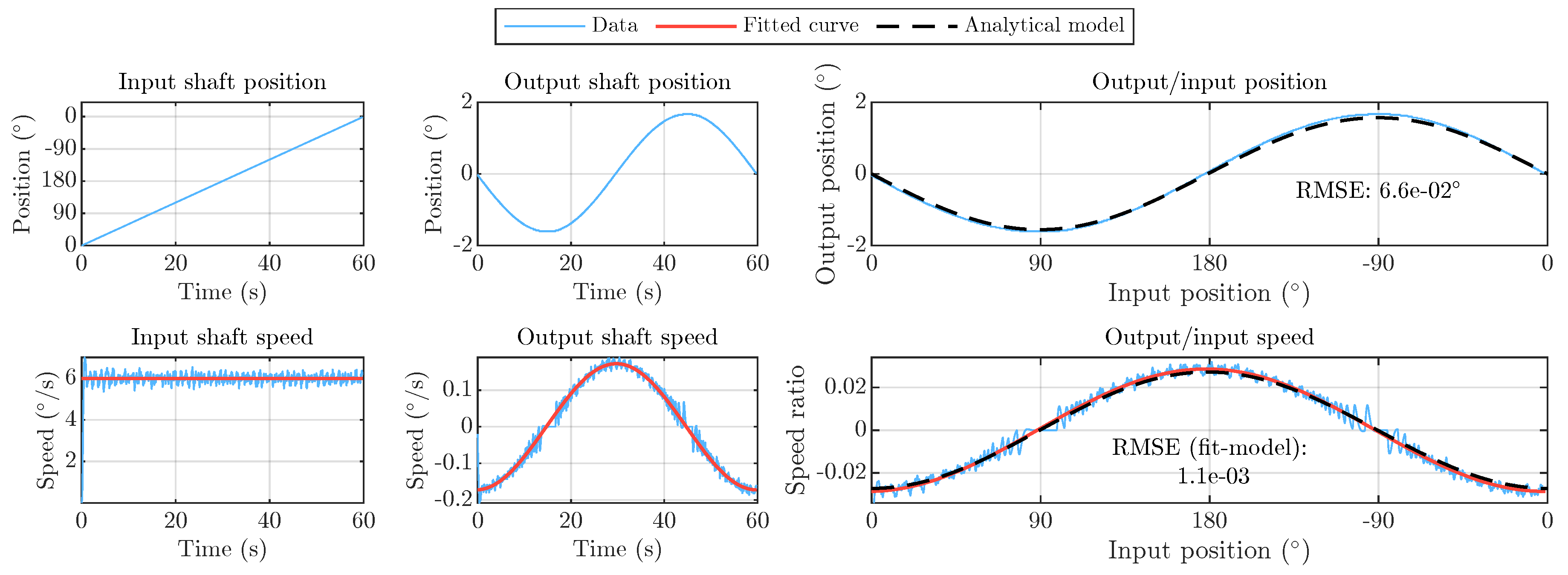
To estimate the input and output shaft speeds, a linear fit was found for the input shaft position data and a sine curve was fitted to the output shaft position data; the first derivatives of these curves were then taken as the experimental speeds, the ratio of which was used as the measured inverse transmission ratio to compare with the model (see (17)). The numerical differentiation of the position data with a light Butterworth filter applied was also found as a reference for the shaft speeds.
The results of the experiment are given in Figure 10. There was a small error in the kinematic relationship between the input and output positions and , with a RMSE of 6.6e-2∘ compared to an output range of motion of about . A line with equation was fitted to the input position data, and a sine curve with equation was fitted to the output position data. The derivatives of the fits were used to find the position-dependent (inverse) transmission ratio. The RMSE of the predicted and experimentally measured transmission ratio curves was 1.1 × 10⁻³ compared to a peak of about .
6. Discussion and Conclusion
The predictions by the analytical model of the TTM joint positions and output shaft speed show great agreement with the numerical simulation in Adams, verifying the basic accuracy of the model. Although the experimental results show some small deviations compared with the predicted output shaft motions, the agreement is overall still good, and the discrepancies can be explained by geometrical uncertainties and material flexibility inherent in the plastic additive manufacturing of a down-scaled prototype.
A 5-bar tilting mechanism has been proposed and designed for the trolley tilting joint of the BBVT and a detailed kinematic model has been derived, verified by numerical simulation, and validated by experiment. Thus, the kinematic relationships between the mechanism’s input and output position, speed, and torque have been shown. In addition, the relationships of the base transmission ratio, output range of motion, output axis load, and input axis load to the cam eccentricity a and tilting plate length d have been detailed, allowing for intelligent dimensioning of these parameters together with the joint gearbox(es) and actuator(s). The model has thus been applied in designing and optimizing the mechanism with respect to the very large static loads which it will see during operation within the future DEMO power plant, supporting the feasibility of the TTM as a solution for safely lifting the BB segments.
Due to the 3D-printing process, the down-scaled TTM lacks the manufacturing precision and material stiffness required for a highly accurate validation of the kinematic model. This flexibility also prevents carrying out experiments to validate the mechanical advantage predicted by the model. Thus, a high-precision down-scaled prototype constructed with sturdier materials could be manufactured in the future to enable fully validating the analytical model.
Since the TTM is only foreseen to be used at low speeds, a multibody dynamics model of the mechanism is not considered necessary for now. However, the derived kinematic model can be used as a basis for future modelling, potentially including dynamic effects, as well as control solutions. More detailed design explorations guided by the model can also be carried out.
Author Contributions
Conceptualization, C.B., R.M., and G.J.; methodology, H.D.; software, H.D.; validation, H.D.; formal analysis, H.D.; investigation, H.D.; resources, X.Z.; data curation, H.D.; writing—original draft preparation, H.D.; writing—review and editing, X.Z.; visualization, H.D.; supervision, X.Z.; project administration, X.Z.; funding acquisition, X.Z. All authors have read and agreed to the published version of the manuscript.
Funding
This work has been carried out within the framework of the EUROfusion Consortium, funded by the European Union via the Euratom Research and Training Programme (Grant Agreement No 101052200 — EUROfusion).
Data Availability Statement
Dataset available on request from the authors.
Conflicts of Interest
The authors declare no conflicts of interest. The funders had no role in the design of the study; in the collection, analyses, or interpretation of data; in the writing of the manuscript; or in the decision to publish the results.
Abbreviations
The following abbreviations are used in this manuscript:
| BB | Breeding blanket |
| BBVT | Breeding blanket vertical transporter |
| TTM | Trolley tilting mechanism |
References
- Federici, G.; Baylard, C.; Beaumont, A.; Holden, J. The Plan Forward for EU DEMO. Fusion Engineering and Design 2021, 303 173, 112960. [CrossRef]
- Donne, A.J.H. The European Roadmap towards Fusion Electricity. Philosophical Transactions of the Royal Society A: Mathematical, 305 Physical and Engineering Sciences 2019, 377, 20170432. [CrossRef]
- Federici, G. Testing Needs for the Development and Qualification of a Breeding Blanket for DEMO. Nucl. Fusion 2023, 63, 125002. 30. [CrossRef]
- Farfaletti-Casali, F.; Booker, D.; Buzzi, U.; Casini, G.; Gritzmann, P.; Cardella, A. The Interaction of Systems Integration, Assembly, 309 Disassembly and Maintenance in Developing the INTOR-NET Mechanical Configuration. Nuclear Engineering and Design. Fusion 310 1984, 1, 115?125. [CrossRef]
- Bachmann, C.; Gliss, C.; Janeschitz, G.; Steinbacher, T.; Mozzillo, R. Conceptual Study of the Remote Maintenance of the DEMO 312 Breeding Blanket. Fusion Engineering and Design 2022, 177, 113077. [CrossRef]
- Bachmann, C.; Janeschitz, G.; Fanelli, P.; Gliss, C.; Mollicone, P.; Muscat, M.; Stefanini, C.; Steinbacher, T.; Dominguez, J.V.; Vigano, 314 F.; et al. Progress in the Development of the In-Vessel Transporter and the Upper Port Cask for the Remote Replacement of the 315 DEMO Breeding Blanket. Fusion Engineering and Design 2023, 194, 113715. [CrossRef]
- Froio, A.; Bertinetti, A.; Del Nevo, A.; Savoldi, L. Hybrid 1D + 2D Modelling for the Assessment of the Heat Transfer in the EU 317 DEMOWater-Cooled Lithium-Lead Manifolds. Energies 2020, 13, 3525. [CrossRef]
- Bachmann, C.; Gliss, C.; Hartl, T.; Hernandez, F.; Maione, I.; Steinbacher, T.; Vizvary, Z. Mechanical Support Concept of the 319 DEMO Breeding Blanket. Fusion Engineering and Design 2021, 173, 112840. [CrossRef]
- Bachmann, C.; Ciattaglia, S.; Cismondi, F.; Eade, T.; Federici, G.; Fischer, U.; Franke, T.; Gliss, C.; Hernandez, F.; Keep, J.; et al. 321 Overview over DEMO Design Integration Challenges and Their Impact on Component Design Concepts. Fusion Engineering and 322 Design 2018, 136, 87?95. [CrossRef]
- Vizvary, Z.; Richiusa, M.L.; Bachmann, C.; Maione, I.A.; Vorpahl, C. Status of the DEMO Blanket Attachment System and 324 Remaining Challenges. Fusion Engineering and Design 2020, 151, 111357. [CrossRef]
- Steinbacher, T.; Bachmann, C.; Gliss, C.; Janeschitz, G.; Mozzillo, R. Design of the Gripper Interlock That Engages with the DEMO 326 Breeding Blanket during Remote Maintenance. Fusion Engineering and Design 2023, 193, 113641. [CrossRef]
- Coleman, M.; Sykes, N.; Cooper, D.; Iglesias, D.; Bastow, R.; Loving, A.; Harman, J. Concept for a Vertical Maintenance 329 Remote Handling System for Multi Module Blanket Segments in DEMO. Fusion Engineering and Design 2014, 89, 2347?2351. 33. [CrossRef]
- Alizade, R.I.; Duffy, J.; Azizov, A.A. Mathematical Models for Analysis and Synthesis of Spatial Mechanisms?II: Five-link Spatial 332 Mechanisms. Mechanism and Machine Theory 1983, 18, 309?315. [CrossRef]
Figure 1.
The DEMO tokamak and its vertical breeding blanket maintenance concept. (a) DEMO tokamak components, reproduced from [7]; (b) BBVT handles a BB segment via the upper port. Reproduced from [6].
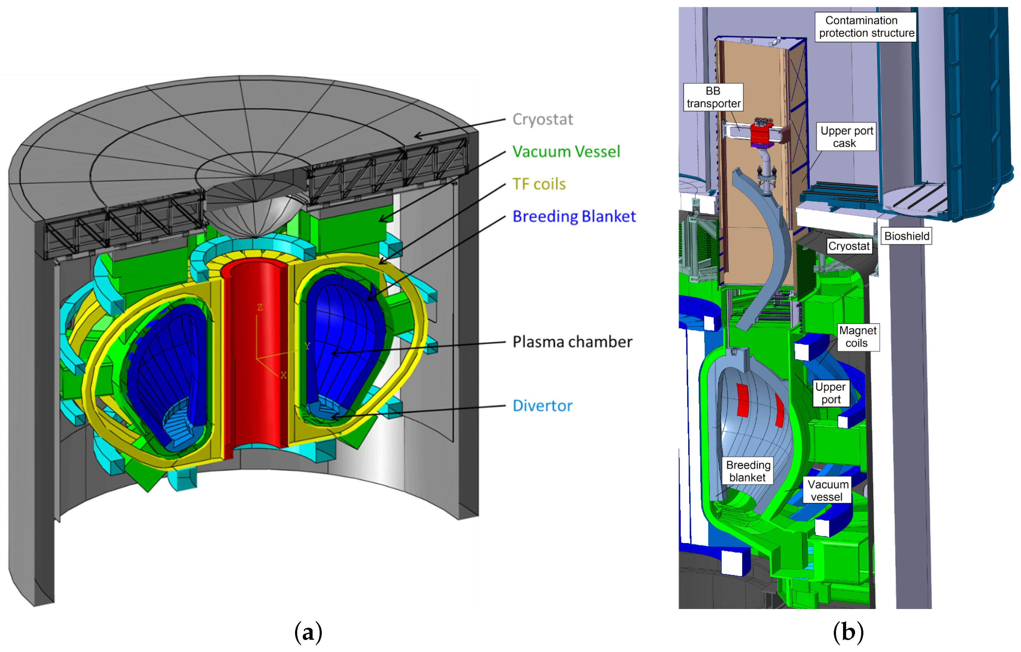
Figure 2.
The trolley tilting joint is needed to avoid damage to the toroidal supports when lifting the lateral BB segments by applying a counteracting radial moment. (a) BB segment supports, including toroidal shear key pockets. Reproduced from [8]. (b) Left: toroidal supports become loaded during initial lifting. Right: application of a radial moment relieves the supports.
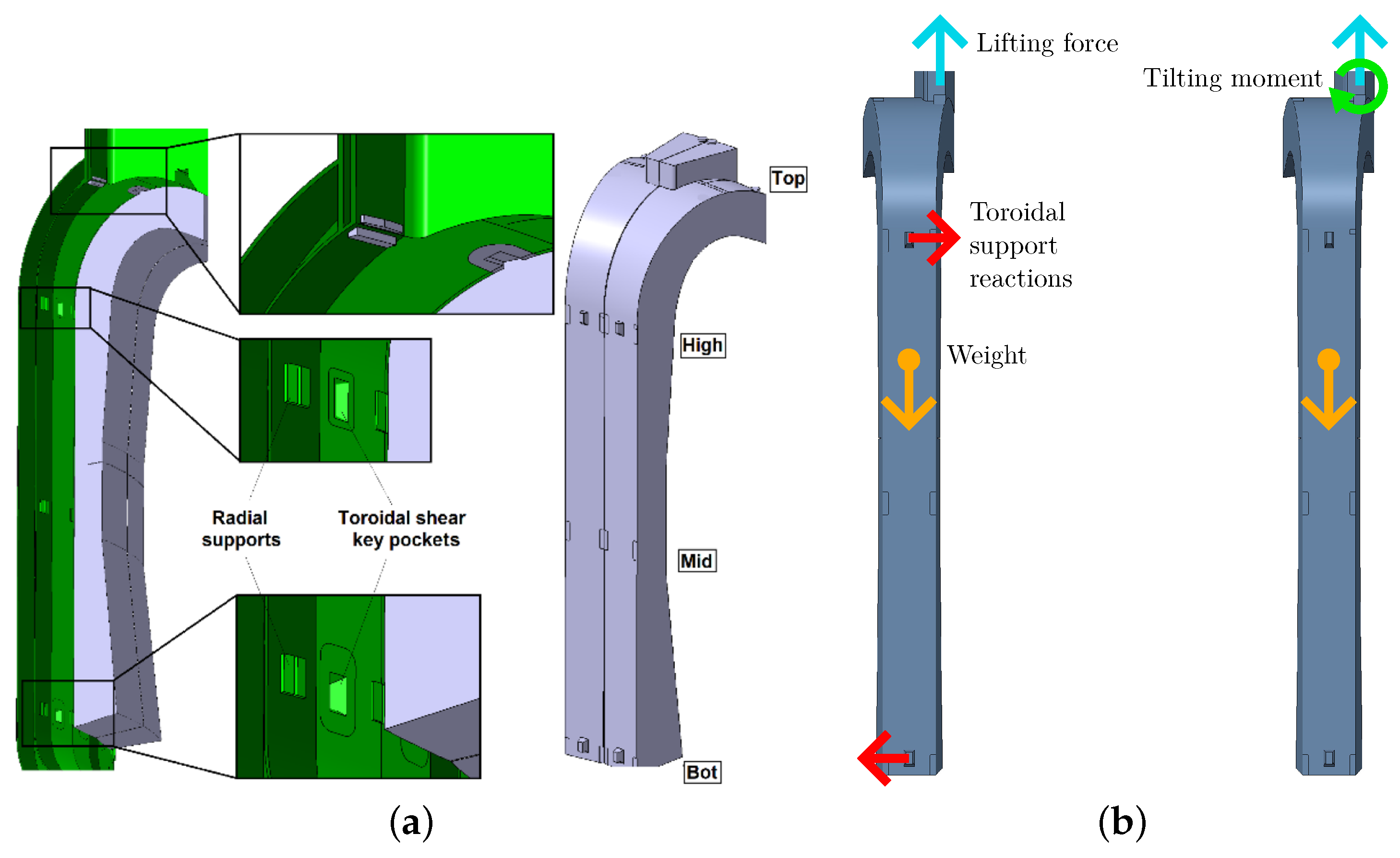
Figure 3.
Overview schematic of the BBVT robotic manipulator, with blank space where a trolley tilting mechanism is needed.
Figure 3.
Overview schematic of the BBVT robotic manipulator, with blank space where a trolley tilting mechanism is needed.
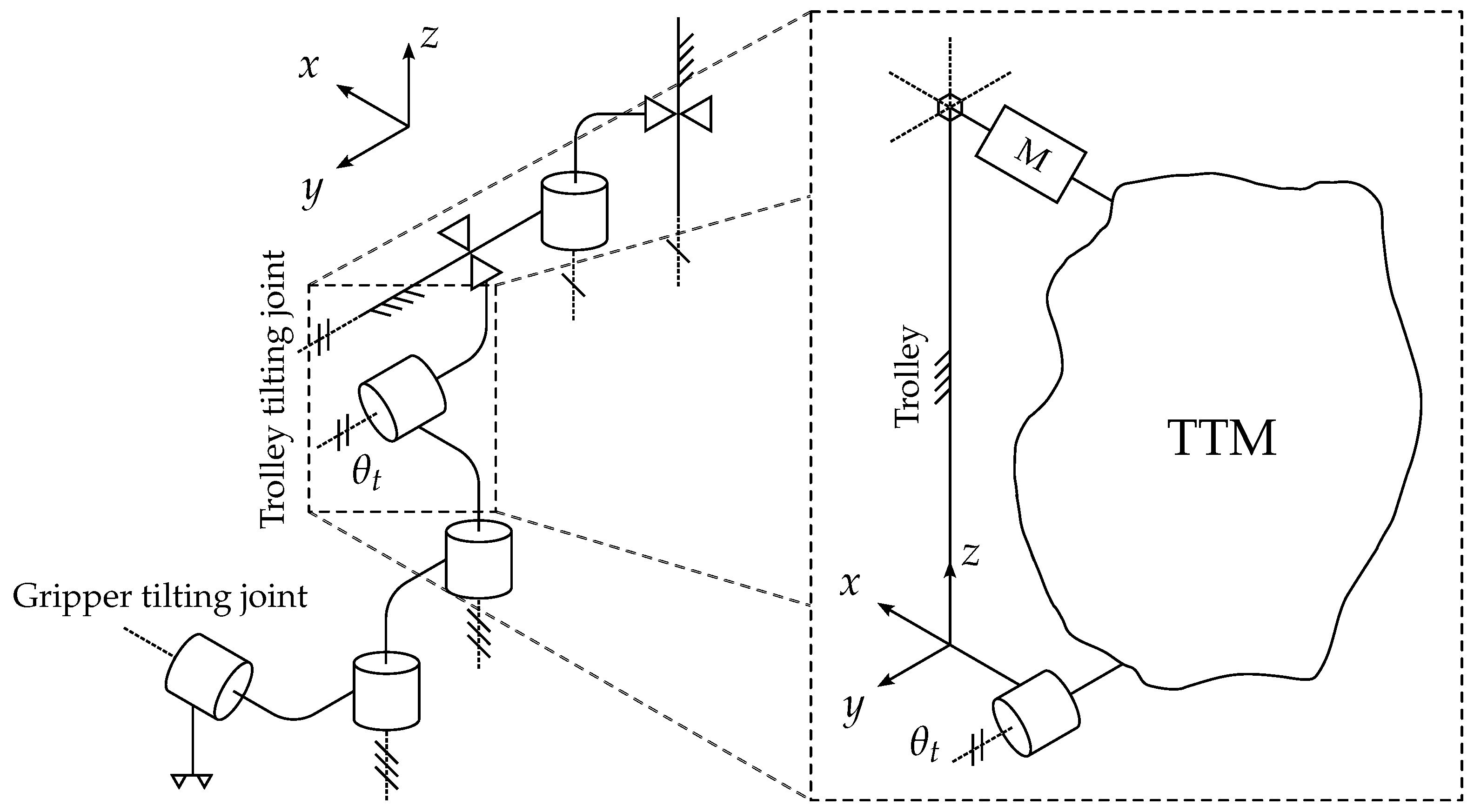
Figure 4.
The trolley tilting mechanism (TTM). (a) 3-D model of the BBVT trolley (red, with partial cutaway). TTM links are marked a–d. Left: overview with dashed lines indicating input and output axes. Right: closeup of gearbox output shaft with eccentric cam (light gray), spherical bearing (dark gray) and rod (magenta). (b) TTM schematics from radial view (left) and toroidal view (right). The angle variables and dimensions used in the kinematic constraint equations are labeled. The notation and has been used.
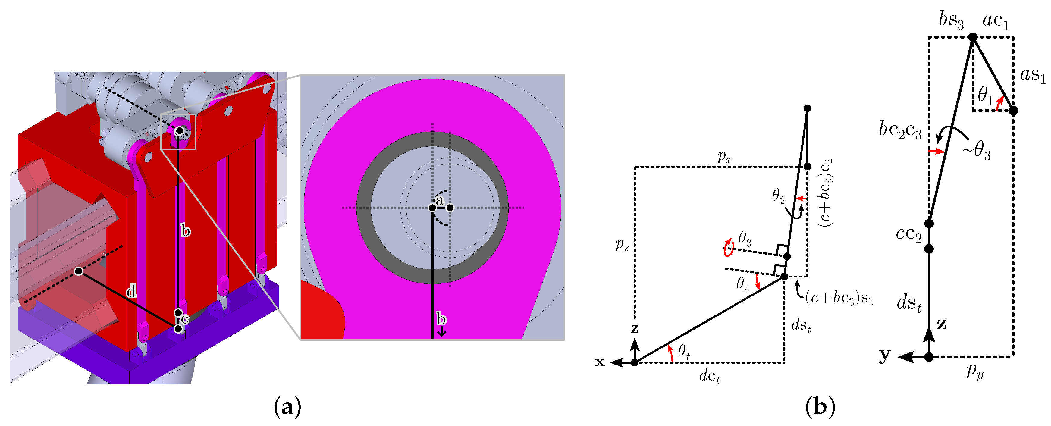
Figure 5.
Geometry factor () as a function of the TTM input angle for different combinations of mobile bar lengths a, b, c, and d, illustrating the position-dependent nature of the mechanism transmission ratio and mechanical advantage.
Figure 5.
Geometry factor () as a function of the TTM input angle for different combinations of mobile bar lengths a, b, c, and d, illustrating the position-dependent nature of the mechanism transmission ratio and mechanical advantage.
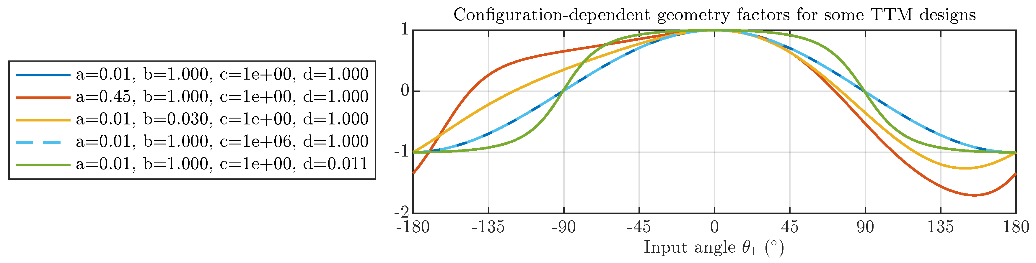
Figure 7.
TTM ADAMS model in different configurations ( mm, mm, mm, and mm).
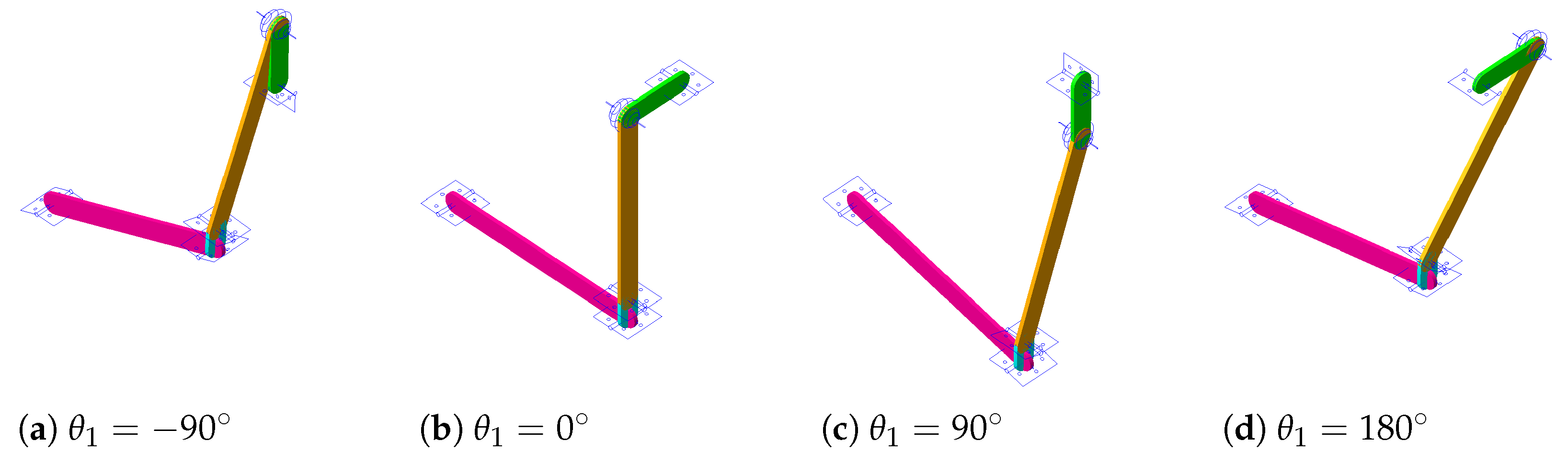
Figure 8.
Relative coordinates and output speed as measured in the TTM ADAMS model compared with the prediction by the analytical model, as functions of the input shaft position.
Figure 8.
Relative coordinates and output speed as measured in the TTM ADAMS model compared with the prediction by the analytical model, as functions of the input shaft position.
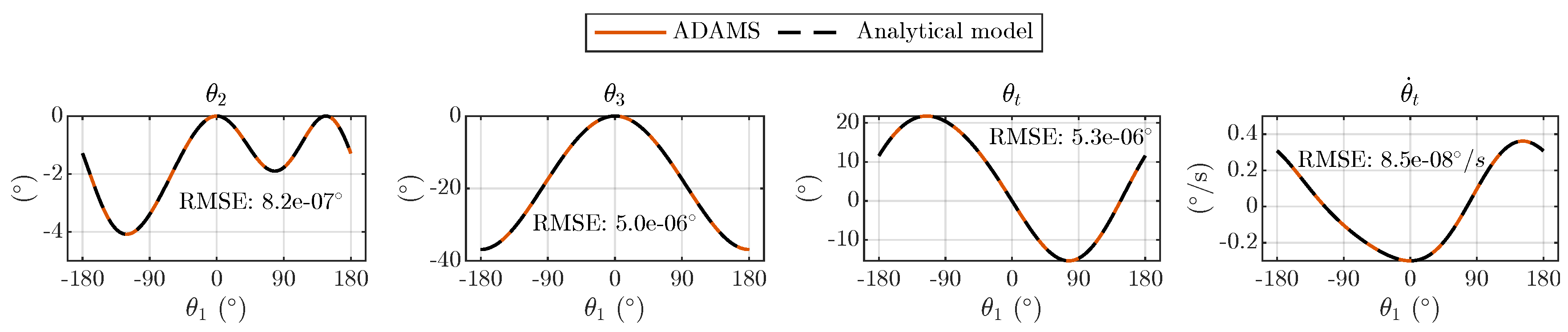
Figure 9.
Experimental setup with down-scaled TTM prototype.
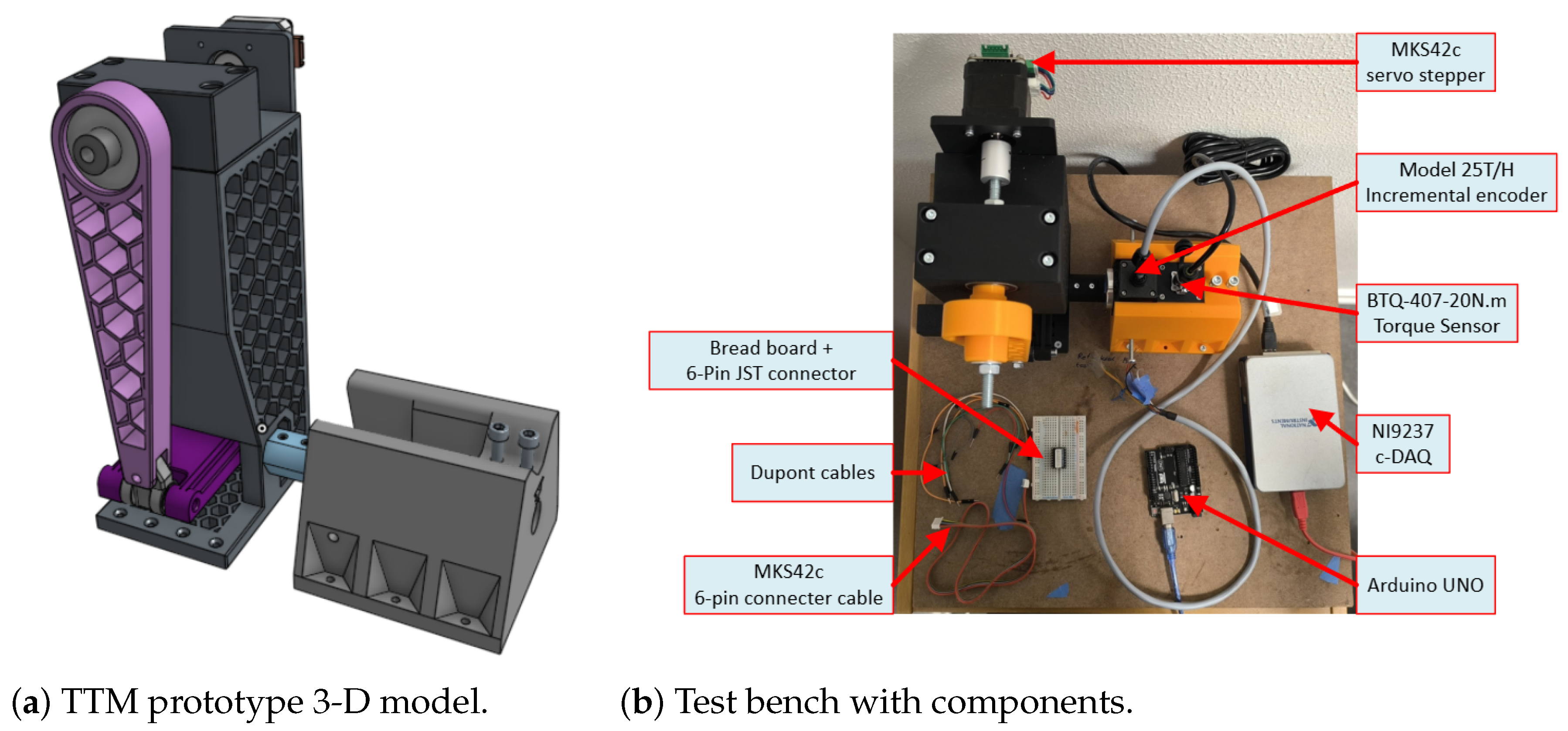
Figure 10.
Input and output shaft positions and speeds measured in the experiment, compared to the model. Speeds were estimated by analytical differentiation of curves fitted to the position data (red), and by numerical differentiation of the shaft positions (light blue).
Figure 10.
Input and output shaft positions and speeds measured in the experiment, compared to the model. Speeds were estimated by analytical differentiation of curves fitted to the position data (red), and by numerical differentiation of the shaft positions (light blue).
Disclaimer/Publisher’s Note: The statements, opinions and data contained in all publications are solely those of the individual author(s) and contributor(s) and not of MDPI and/or the editor(s). MDPI and/or the editor(s) disclaim responsibility for any injury to people or property resulting from any ideas, methods, instructions or products referred to in the content. |
© 2025 by the authors. Licensee MDPI, Basel, Switzerland. This article is an open access article distributed under the terms and conditions of the Creative Commons Attribution (CC BY) license (http://creativecommons.org/licenses/by/4.0/).
Copyright: This open access article is published under a Creative Commons CC BY 4.0 license, which permit the free download, distribution, and reuse, provided that the author and preprint are cited in any reuse.


