Submitted:
22 April 2025
Posted:
22 April 2025
You are already at the latest version
Abstract
The influence of different sheet-layer combination modes on mechanical property of self-piercing riveting joint in three-layer sheets were studied by means of tests with simulation. The shear and cross tensile tests were carried out on three-layer AA6063-T6 riveted joint under different sheet-layer combination modes. The test result shows that joint mechanical properties and failure modes are different under different sheet combination modes. Meanwhile, the detail finite element model of joint under different sheet-layer combination modes was established, and the failure process of joint in two working conditions were analyzed by numerical simulation. The analysis shows that the stress deformation of sheet-layer is affected by different sheet-layer combination modes, which leads to the difference of joint mechanical properties; The strength of joint under different sheet-layer combination modes are affected by the strength of different sheet-layer and interlock.
Keywords:
self-piercing riveting
; three-layer sheets
; numerical simulation
; sheet-layer combination modes
; mechanical property
1. Introduction
With the continuous growth of the number of motor vehicles in China and the increasing severity of energy crises and environmental pollution, automotive lightweight design has drawn increasing attention. In view of the low density and high specific strength of aluminum alloy, its application in vehicle bodies has become an effective solution for achieving lightweight vehicle structures. However, due to the properties of aluminum alloy, such as low melting point, high thermal conductivity, and good electrical conductivity, welding often leads to issues such as spatter, poor weld quality, and defects in the weld nugget, which hinder their application in vehicle bodies. Self-piercing riveting, as a cold-forming joining process without heat input, ensures stable joint quality and effectively addresses the challenges of aluminum alloy welding, making it one of the primary connection processes for lightweight metals like aluminum alloy at present [1,2].
In recent years, researchers have conducted extensive studies on the self-piercing riveting (SPR) process, focusing on several key areas, including process parameter optimization, effects of material compatibility and surface treatment, joint performance testing and evaluation. Porcaro et al. [3] conducted numerical simulations and experimental studies on the self-piercing riveting forming process of different aluminum alloy riveted combinations. Amro et al. [4] investigated the damage mechanisms of polymer-metal joints during SPR and explored the effects of riveting velocity on composite layer damage. They also analyzed the failure mechanisms of the joints under lap-shear and pure tension loads using numerical simulation. Uhe et al. [5] assessed the influence of rivet coatings, including Almac® and zinc-nickel with topcoat, on friction during SPR through friction tests, experimental joining trials, and numerical simulations. Their findings indicated that while surface conditions can alter friction and joint properties, they do not restrict the operational capability of SPR, with uncoated rivets performing similarly to coated ones. Mori et al. [6] investigated the self-piercing riveting forming process of three-layer sheets and explored the joint connection performance through tests with different thicknesses and strengths of sheet combinations. Rusia et al. [7] developed a comprehensive simulation approach to analyze SPR joint failure, focusing on material damage and failure modeling, particularly for 2-sheet joints. They emphasized the importance of accurate damage prediction for the development of SPR connections in future applications involving 3-sheet joints. Mucha et al. [8] conducted shear and peel tests to determine the effect of different rivet types on the mechanical properties of single-lap riveted joints. Lamba et al. [9] compared the resistance spot welding (RSW) performance of AA5754-O and AA6022-T4 aluminum alloys welded to interstitial-free low carbon steel (LCS), highlighting that AA6022-T4 exhibited superior mechanical properties due to lower contact resistance compared to AA5754-O, which experienced degraded weld quality and weaker joint performance. Han et al. [10] performed shear and peel tests on self-piercing riveted joints of multilayer aluminum sheets with different test specimen structures, confirming the influence of test specimen structure on joint mechanical properties. Amundsen et al. [11] investigated the behavior and modeling of Flow-Drilling Screw (FDS) connections under various quasi-static loads, noting that shear-dominated conditions produce higher forces and failures primarily occur due to pull-out from the bottom sheet. Their research also showed that while existing models (e.g., self-piercing rivet and spot weld models) provide acceptable results, further calibration is needed for three-layered connections and shear-dominated loading cases.
In summary, for self-piercing riveted joints, on one hand, process parameters affect joint forming quality and, consequently, joint mechanical properties [12,13]. On the other hand, test specimen structure and overlap configuration also influence joint mechanical properties [14,15]. Therefore, based on previous research, this study employs a combination of simulation and experiments to analyze the mechanical properties of three-layer sheet self-piercing riveted joints under different sheet-layer stress-deformation conditions and investigates the influence of different sheet-layer combination modes on joint mechanical properties.
2. Materials and Methods
2.1. Materials
This study uses aluminum alloy AA6063-T6 with a thickness of 2 mm as the three-layer sheet material for riveting. A rivet with a shank diameter of 5.3 mm and a length of 9 mm is employed for the riveting process. The mechanical properties of both the aluminum alloy sheets and the rivet are presented in Table 1.
2.2. Specimen Preparation
The 2mm thick aluminum alloy sheets are cut into two sizes: 100mm×40mm and 40mm×40mm. Based on the sheet dimensions, three types of sheet-layer combination modes are defined for the three-layer sheet self-piercing riveting joint:
T1: The top and middle sheets are 100mm×40mm, and the bottom sheet is 40mm×40mm.
T2: Both the top and bottom sheets are 100mm×40mm, and the middle sheet is 40mm×40mm.
T3: Both the middle and bottom sheets are 100mm×40mm, and the top sheet is 40mm×40mm.
The schematic diagrams of force distribution for these configurations under shear and cross-tensile conditions are shown in Figure 1. Specifically:
T1: The middle sheet is clamped, and the top sheet is stretched.
T2: The bottom sheet is clamped, and the top sheet is stretched.
T3: The bottom sheet is clamped, and the middle sheet is stretched.
Taking the T1 joint specimen as an example, its geometric dimensions are illustrated in Figure 2. All joint specimens with different sheet-layer combination modes are prepared using the EPRESS hydraulic-driven riveting machine, model VTF-75.
2.3. Shear and Cross-Tensile Test Results Analysis
Shear and cross-tensile tests were conducted on the joint specimens at a stretching speed of 10 mm/min using the universal testing machine CMT4304. The strength of joints under shear and cross-tensile conditions for different sheet-layer combinations is shown in Figure 3. As can be seen from the figure, under shear conditions, the strength of T3 joints was the highest, reaching 9.16 kN; T1 joints had the next highest strength at 8.76 kN; and T2 joints had the lowest strength at 4.62 kN. Under cross-tensile conditions, T2 joints had the lowest strength at 3.19 kN; T1 joints had the highest strength at 4.97 kN; and T3 joints had an intermediate strength at 3.56 kN.
Figure 4 shows the load-displacement curves of joints under the two working conditions for different sheet-layer combinations. By comparing the trends of the curves, it can be observed that under shear conditions, the load for both T1 and T3 joints increased rapidly in the initial stage, reaching the maximum load with gradually decreasing increments. After reaching the maximum load, T1 and T3 joints continued to bear the shear force, with the load gradually decreasing until the joint ultimately failed. The failure displacement for these joints was relatively large. In contrast, T2 joints exhibited lower strength, with significantly different behavior compared to T1 and T3 joints. The load increase was relatively small in the initial stage, and after reaching the maximum load, the load decreased rapidly, leading to quicker joint failure with a smaller failure displacement.Under cross-tensile conditions, the load increments for all three sheet-layer combinations in the initial stage were similar. However, all joints failed immediately after reaching the maximum load. Among them, T1 joints had the largest failure displacement, while T3 joints had the smallest failure displacement. Therefore, considering the results from both shear and cross-tensile tests, joints with different sheet-layer combinations exhibit varying strength and failure displacement under the two working conditions.
2.4. Failure Modes of Joints Under Shear and Cross-Tensile Conditions
Figure 5 illustrates the failure modes of joints with different sheet-layer combinations under shear conditions. For the T1 joint, the failure mode involves the upper sheet being pulled out from the rivet, while the rivet maintains the connection between the middle and lower sheets, as shown in Figure 5a. For the T2 joint, the failure mode is characterized by the rivet being pulled out from the lower sheet, as shown in Figure 5b. Additionally, there are scratches at the riveting location on the lower plate due to the pulling-out action, while the rivet does not fully detach from the upper and middle sheets. The failure mode of the T3 joint is identical to that of the T2 joint, as shown in Figure 5c, with more pronounced scratches at the riveting location on the lower plate.
Figure 6 shows the failure modes of joints under cross-tensile conditions. Consistent with the observations from shear tests, the failure modes of all joints remain the same. For the T1 joint, the failure mode involves the upper sheet being pulled out from the rivet, with the rivet maintaining the connection between the middle and lower sheets, as shown in Figure 6a. For the T2 and T3 joints, the failure mode is characterized by the rivet being pulled out from the lower sheet, as shown in Figure 6b,c, respectively. Therefore, based on the failure modes observed under both shear and cross-tensile conditions, it is evident that joints with different sheet-layer combinations exhibit distinct failure modes under the same working condition.
3. Establishment of Joint Fine Finite Element Model
3.1. Establishment of Model
To better investigate the influence of different sheet-layer combination modes on joint mechanical properties and analyze the differences between joints with various combinations, this study employs finite element software Hyper Mesh/LS-DYNA to establish detailed finite element models for joints with different sheet-layer combinations. Numerical simulations are then conducted to analyze the failure processes of joints under shear and cross-tensile conditions. First, based on the dimensions of the joint forming results, as shown in Figure 7, the rivet and sheets are subjected to rotation treatment to generate the three-dimensional solid model of the joint. A geometric model of the test specimen is also established, comprising four components: the rivet, the upper sheet, the middle sheet, and the lower sheet. Next, a meshing process is performed on the model components. The areas where the rivet and sheets are joined are refined with a solid mesh of 0.25 mm, while the remaining parts of the sheets are coarsely meshed with a solid mesh of 1 mm. Material properties are assigned, and a multilinear elastic-plastic material model is employed. The detailed finite element model of the joint is shown in Figure 8. Subsequently, model parameters are set, defining automatic face-to-face contact between model components with a friction coefficient of 0.2. Additional controls, such as solid element control, contact control, hourglass control, and ALE control, are implemented. Finally, loading and boundary conditions are defined. The LS-DYNA solver is used to analyze and obtain the failure processes of joints with different sheet-layer combinations under the two working conditions.
3.2. Establishment of Model
3.2.1. T1 Plate Layer Combination Method for Clamping the Middle Plate and Stretching the Upper Plate
Figure 9 shows the failure process of the T1 plate-layer combination joint under shearing conditions. When the stretching begins, the upper plate and the middle plate are stress concentrated on the left and right sides of the rivets respectively. Under the action of the shear force of the upper plate and the middle plate, the rivets are slightly inclined and form maximum stress on the tip of the left leg. During stretching, as the shear force of the upper plate increases, the rivets are obviously tilted, and the left leg tends to be pulled up, and the stress increases further under the action of self-locking restrictions. At the same time, the middle plate undergoes plastic deformation, resulting in an increase in contact area with the right side of the rivet, while the upper plate and the lower plate undergoes bending deformation. Under the combined action of the continuous increase in the contact area between the rivet and the middle plate and the increasing shear force, the rivet is further inclined. Since the strength of the rivet is greater than the strength of the upper plate, the interaction between the rivet and the upper plate causes the deformation and expansion of the punching hole of the upper plate, resulting in the pulling of the upper plate from the rivet and causing the joint failure.
During the shear failure process of the T1 joint, the rivet remains connected to the middle and lower plates and is self-locking, and the upper plate is less strong, and the punching hole is deformed and expanded, which leads to it being pulled out of the rivet. Therefore, in this plate-layer combination, the shear strength of the joint is affected by the strength of the upper plate, the self-locking strength of the rivet and the middle and lower plates. When the strength of the upper plate is smaller than the self-locking strength of the rivet and the middle and lower plates, the upper plate undergoes plastic deformation, causing the punching to expand, causing the upper plate to be easily pulled out of the rivet. At the same time, compared with the T2 joint, since the self-locking of the T1 rivet and the middle and lower plates is greater than that of the T2 rivet and the lower plate, the shear strength of the T1 joint is greater than that of the T2 joint with the same strength as the upper plate.
The cross tensile strength of the T1 plate layer combination joint is the largest, and its failure process under cross tensile conditions is shown in Figure 10. At the beginning, the self-locking part of the upper plate and the rivet forms maximum stress under the squeeze of the rivet and the middle plate, and the stress concentration of the rivet occurs due to the self-locking of the rivet. As the tensile force increases, the upper plate undergoes plastic deformation, and the stress disperses around the punching hole of the sheet, and there is a tendency to expand at the punching hole. Under the combined action of mid-plate stretching and self-locking restrictions, the middle and lower plates are stress concentrated on the contact part of the rivet’s legs, while the rivets form the maximum stress at the tip of the leg. Under the continuous action of tensile force, the plastic deformation at the punching hole of the upper plate continues to increase. When the punching hole expands to greater than the diameter of the rivet head, the upper plate is instantly pulled out of the rivet, causing the joint failure.
During the cross-stretch failure process of T1 joint, the stretched middle plate is equivalent to the stretched middle and lower layers of plates with a total thickness of 4mm. Compared with the stretched upper plate layer with a thickness of only 2mm, it can withstand greater tensile force. Therefore, the upper plate is deformed and expanded due to its smaller strength. At the same time, the rivets have large self-locking with the middle and lower plates, making it difficult to pull out from the middle and lower plates. Then, under the action of expanding at the punching hole of the upper plate, the upper plate is pulled out from the rivet. Therefore, in this plate layer combination method, the tensile strength of the joint cross is affected by the strength of the upper plate. Since the upper plate strength of the three types of joints is the same, the self-locking of the T1 joint rivet and the middle and lower plates is greater than that of the T2 and T3 joint rivet and the lower plates, and the rivets are more difficult to pull out. Therefore, the cross tensile strength of the T1 joint is the largest, and the failure mode is also different from them.
3.2.2. T2 Plate Layer Combination Method for Clamping the Lower Plate and Stretching the Upper Plate
The shear strength of the joints in T2 plate layer combination method is the smallest among the three plate layer combination methods, and the failure process under shearing conditions is shown in Figure 11. In the beginning, the tendency of the rivets to be pulled up creates maximum stress at the tip of the left leg and creates stress concentration on the head of the self-locking part of the upper plate on the right. The lower plate is subjected to the rivet inclination and the middle plate, and a local stress concentration is formed on the right side of the rivet legs. During the stretching process, although the mid plate is not directly stretched, it tilts with the rivet under the action of self-locking. The left side of the upper plate and the right side of the lower plate are bent and deformation due to the combined action of the inclination of the middle plate and tensile force. The part of the rivet on the right side of the upper plate tends to be pulled out. The riveted part of the lower plate expands due to plastic deformation, and the tendency of the rivet being pulled up is obvious. When the shear force increases, the lower plate riveting is further expanded. When the rivet inclination becomes larger, the rivet is pulled out of the lower plate and the T2 joint fails to lock.
During the shear failure of the T2 joint, the deformation and expansion of the lower plate riveting and the rivet tilt work together to make the rivet easy to pull out of the lower plate, resulting in the joint self-locking failure. Therefore, in this plate-layer combination, the shear strength of the joint is affected by the lower plate strength and the rivet and lower plate self-locking strength. At the same time, during the stress process of the T2 joint plate layer, a bending moment with the rivet as the axis is formed, which is larger than the bending moment with the rivet head to the middle of the T1 joint formed by the middle and upper and middle plates of the T1 joint. Therefore, the T2 joint rivet is more likely to tilt than the T1 joint rivet, making it easier to overcome the self-locking between the rivet and the lower plate. Therefore, the T2 shear strength is less than the shear strength of the T1 joint.
Figure 12 shows the failure process of the T2 plate combination joint under cross tensile conditions. When stretching begins, the rivet forms the maximum stress on the tips of the left and right legs due to the self-locking effect, while the upper and lower plates form stress concentration on the self-locking part of the rivet due to the tensile force. When stretching continuously, the stress on the tips of the legs on both sides of the rivet increases, the upper and lower plates undergo plastic deformation, and the stress is distributed around the plate. Since the strength of the rivet is greater than that of the lower plate, the lower plate rivet joint expands under the combined action of the upward stretching and plastic deformation of the rivet, which causes the rivet to be pulled out of the lower plate and cause the joint to fail.
During the cross-stretch failure process of T2 joint, since the self-locking of the rivet and the upper plate is greater than that of the rivet and the lower plate, when the upper plate and the lower plate are the same deformation, the self-locking of the lower plate and the rivet is more likely to fail. Therefore, in this plate-layer combination, the tensile strength of the joint is affected by the lower plate strength and the self-locking strength of the rivet and the lower plate. When the tensile load causes plastic deformation of the lower plate and is greater than the self-locking strength between the rivet and the lower plate, the rivet is pulled out of the lower plate, causing the joint to fail.
3.2.2. T3 Plate Layer Combination Method for Clamping the Lower Plate and Stretching the Upper Plate
The shear strength of the T3 plate combination joint is the largest, which is related to the stress of the T3 joint plate layer under shearing conditions. Figure 13 shows the failure process of the T3 plate combination joint in shearing conditions. As can be seen from the figure, when the shearing condition begins, the stress is concentrated on the right side of the rivet, the rivet is inclined, and the maximum stress is formed on the tip of the leg on the right side of the rivet. Due to the shear force, the middle plate forms stress concentration in the contact part with the rivet. As the shear force increases, the rivet becomes more inclined and it constantly squeezes the self-locking part on the right side of the upper plate. Plastic deformation occurs on the right side of the upper plate and the load is transferred to the right side of the middle plate. On the right side of the middle plate, under the combined action of shear force and transfer load, plastic deformation occurs and tends to be pulled out. At the same time, the upper plate is located between the rivet head and the middle plate, and under the action of the bending deformation of the middle plate and the self-locking limit of the rivet, it also undergoes a certain degree of bending deformation. The lower plate is deformed and expanded due to the combined effect of shear force and self-locking. The left leg of the rivet tends to be pulled up, and the right leg of the rivet remains in the lower plate. When the shear force increases, the rivet inclination becomes larger, and the right side of its legs can be pulled out from the lower plate, the T3 joint fails.
During the shear failure of the T3 joint, the middle plate first undergoes plastic deformation, while the upper plate undergoes plastic deformation under the joint action of the middle plate and the rivet. Since the upper middle plate is kept connected to the rivet through a self-locking, it is equivalent to stretching the upper middle two layers of sheets when stretching the middle plate, and their contact surface with the rivet is relatively large. The lower plate and the rivet have only contact with the self-locking part, and the area that can withstand the load is smaller than the area that can withstand the load when the upper middle plate and the rivet are in contact. Therefore, in the process of increasing shear force, compared with the upper middle plate with high load-bearing capacity, the lower plate is more likely to undergo plastic deformation, resulting in deformation and expansion of the riveting, which in turn causes the self-locking to fail and the rivets to be pulled out of the lower plate. In this plate-layer combination, the plastic deformation at the lower plate rivet makes the inclined rivet easy to pull out, so the shear strength of the joint is affected by the lower plate strength and the self-locking strength of the rivet and the lower plate. At the same time, compared with T1 and T2 joints, the T3 joints are combined to stretch the middle plate. On the one hand, the shear force needs to plastically deform the upper middle plates, so that the rivets tilt under the shear force of the two plates; on the other hand, the shear force also needs to plastically deform the lower plate, and the rivets are deformed and expanded, so that the rivets are easily pulled out. Therefore, the combination of the plate layer requires a large shear force to deform and expand the riveted rivets at the inclined and lower plate, thereby causing the joint to fail. Therefore, the shear strength of the M3 joint is the largest among the three.
Figure 14 shows the failure process of the T3 plate combination joint under cross tensile conditions. When the stretching begins, stress concentration occurs on the outer periphery of the rivet, and under the action of self-locking, the maximum stress is formed at the tips of the left and right legs, while each plate layer forms stress concentration in the self-locking part under the action of self-locking. Among them, although the upper plate is not stretched, it also undergoes stress changes under the action of middle plate load and self-locking. During the stretching process, the lower plate undergoes obvious plastic deformation due to large stress, resulting in a tendency to expand at the riveting point. Under the action of tensile force, the rivets form the maximum stress on the tip of the leg due to the self-locking restriction. When the tensile force increases, the plastic deformation at the lower plate riveting increases and expands to enough to pull out the rivet legs, the rivet is instantly pulled out from the lower plate and the joint fails.
During the cross-stretch failure process of T3 joint, the stretched middle plate is equivalent to stretching the upper and middle layers of the upper and middle layers of the plate layer, while the stretched lower plate is only stretched with a thickness of 2mm. The yield deformation of the lower plate with a thickness of 2mm is easier to produce deformation of the upper and middle layers of 4mm is easier to produce deformation. Therefore, when the tensile force is the same, the lower plate is more likely to produce deformation, causing deformation and expansion at the riveting, thereby pulling out the rivet. Therefore, the tensile strength of the joint cross is affected by the lower plate strength and the self-locking strength of the rivet and the lower plate. At the same time, by comparing the cross tensile strength of the T2 joint, we can see that the tensile strength of the two joints is related to the lower plate strength, the self-locking strength of the rivet and the lower plate, while the lower plate strength of the T2 and T3 joints, the self-locking strength of the rivet and the lower plate are also the same. Only the plate layer combination method is different, so the cross tensile strength of the two joints is similar.
4. Conclusions
(1) Due to the different combination methods of the plate layer, the shear strength and the cross tensile strength are different, and the corresponding failure modes are also different. The T1 joint has better comprehensive mechanical properties, while the T3 joint is worse. In practical applications, when the joint mainly bears shear force, the T3 plate combination method is preferred; when the joint mainly bears tensile force, the T1 plate combination method is preferred.
(2) In the T1 plate layer combination method, the shear strength of the joint is affected by the upper plate strength, the self-locking strength of the rivet and the middle and lower plates; the cross tensile strength of the joint is affected by the upper plate strength. It is possible to consider replacing the upper plate with a higher strength sheet to improve the mechanical properties of the joint.
(3) In the T2 plate layer combination method, the shear strength and cross tensile strength of the joint are affected by the lower plate strength, the rivet and the lower plate self-locking strength. It is possible to consider replacing the lower plate with a higher strength plate to improve the mechanical properties of the joint.
(4) In the T3 plate layer combination method, the shear strength and cross tensile strength of the joint are affected by the lower plate strength, the rivet and the lower plate self-locking strength. It is possible to consider replacing the lower plate with a higher strength plate to improve the mechanical properties of the joint.
Author Contributions
Conceptualization, Z.H. and S.M.; methodology, Z.H.; validation, Z.H., S.M. and Y.W.; formal analysis, Z.H., S.M.; investigation, Z.H.; resources, S.M.; data curation, Z.H.; writing—original draft preparation, Z.H.; writing—review and editing, Z.H., S.M. and Y.W.; visualization, Z.H. and S.M.; supervision, Z.H.; project administration, Z.H. and S.M.; funding acquisition, S.M. All authors have read and agreed to the published version of the manuscript.
Funding
This research is thankful for the support of Guangxi major science and technology project (AA23062065), Liuzhou science and technology project (2023PRJ0102) the open subject project of the State Key Laboratory of Featured Metal Materials and Life-cycle Safety for Composite Structures (MMCS20230F08).
Institutional Review Board Statement
Not applicable.
Informed Consent Statement
Not applicable.
Data Availability Statement
The original contributions presented in this study are included in the article. Further inquiries can be directed to the corresponding author.
Conflicts of Interest
The authors declare no conflicts of interest.
References
- Xie, X. P.; et al. Simulation and Optimization of Nonlinear Structures on Low Frequency Vibration and Noise of Lightweight Car Body. International Journal of Computational Methods, 2020.
- Camberg, Alan A et al. Tailored Stacked Hybrids – An Optimization-Based Approach in Material Design for Further Improvement in Lightweight Car Body Structures. In Technologies for Economical and Functional Lightweight Design, Location, Country, Date (Day Month Year), 2019.
- R. Porcaro, A.G. Hanssen, M Langseth, et al. Self-piercing riveting process: An experimental and numerical investigation[J]. Journal of Materials Processing Technology, 2006, 171(1): 10-20. [CrossRef]
- Amro, El-Karef and Afia Kouadri-Henni. Experimental Investigation of Damage and Failure Mechanisms of Polymer-Metal Joints Assembled by Self-Piercing Riveting. In ESAFORM 2021, Location, Country, Date (Day Month Year), 2021.
- Uhe, Benedikt et al. Influence of Rivet Coating on Friction during Self-Piercing Riveting. Key Eng. Mater. 2021, 883, 11–18.
- K. Mori, Y. Abe, T. Kato. Self-pierce riveting of multiple steel and aluminum alloy sheets[J]. Journal of Materials Processing Technology, 2014, 214(1): 2002-2008. [CrossRef]
- Rusia, Aman et al. Simulation of Self-Piercing Riveting Process and Joint Failure with Focus on Material Damage and Failure Modelling. Journal Name, 2019.
- J. Mucha, W. Witkowski. MECHANICAL BEHAVIOR AND FAILURE OF RIVETING JOINTS IN TENSILE AND SHEAR TESTS[J]. Strength of Materials, 2015, 47(5):755-769.
- Lamba, E. P. Cox, H. S. Welding Research. Abbreviated, 2013.
- L. Han, A. Chrysanthou,K.W. Young. Mechanical behaviour of self-piercing riveted multi-layer joints under different specimen configurations[J]. Materials and Design, 2007, 28(1): 2024-2033.
- Amundsen, D.H.; Gustad, J.U. Behaviour and Modelling of Flow-Drilling Screw Connections. Abbreviated, 2014.
- Schromm, Thomas et al. An attempt to detect anomalies in car body parts using machine learning algorithms, 2019.
- Lee, H.J.; et al. Comparative Analysis of SPR and SPR-Bonded Joints of Hot Press Forming Steel and AA5052 under Corrosive Conditions. J. Weld. Join. 2023. [CrossRef]
- Guo, Z.; et al. The Effects of Three Profiles on the Mechanical Properties and Grain Size of Self-Piercing Riveting Joints Using Ultrasonic Welding. Int. J. Adv. Manufac. Technol. 2023, 129, 4869–4882. [Google Scholar]
- Franco, G.D.; et al. Performance of SPR/Bonded Hybrid Single Lap Joints CFRP/Aluminum, 2011.
Figure 1.
Illustration of different sheet-layer combination.
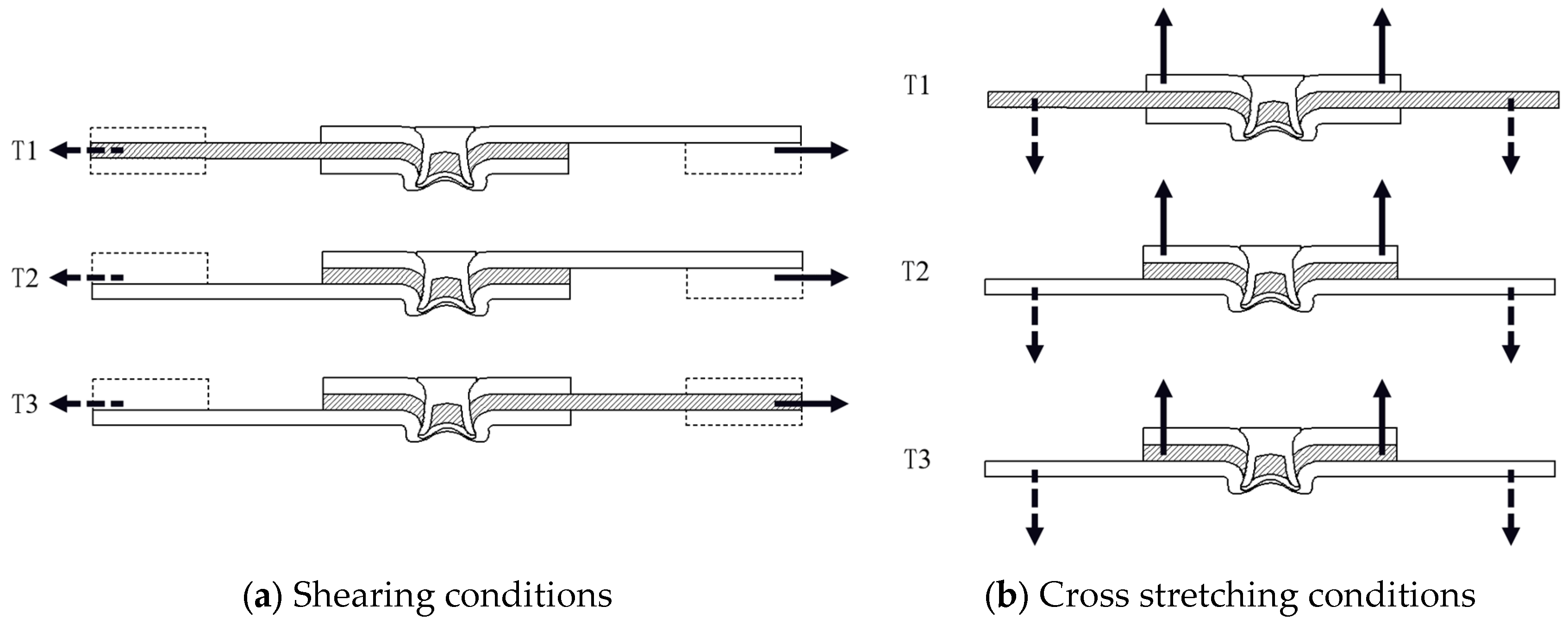
Figure 2.
Geometry of specimen.
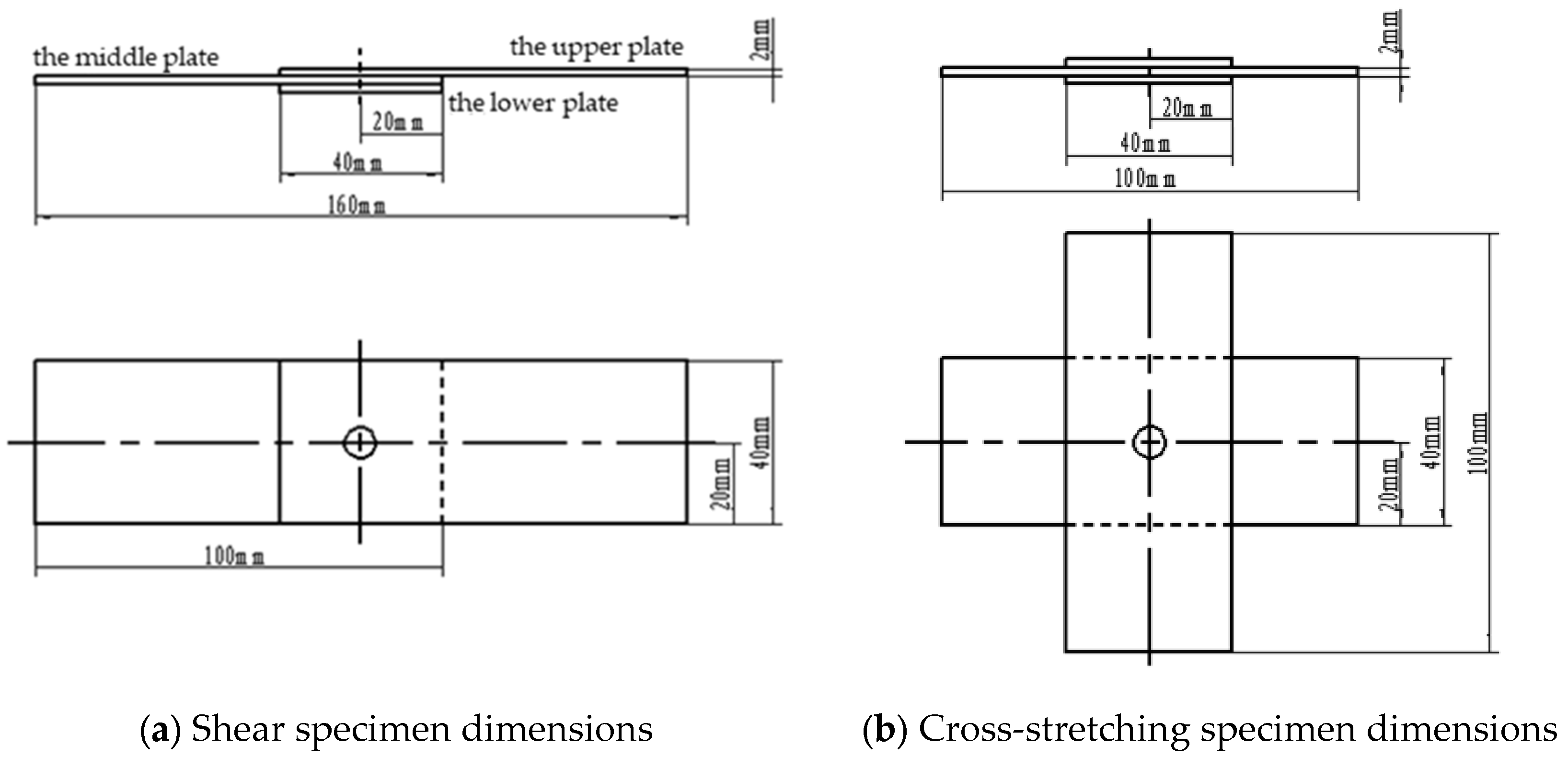
Figure 3.
Joint strength of different sheet-layer combination modes.
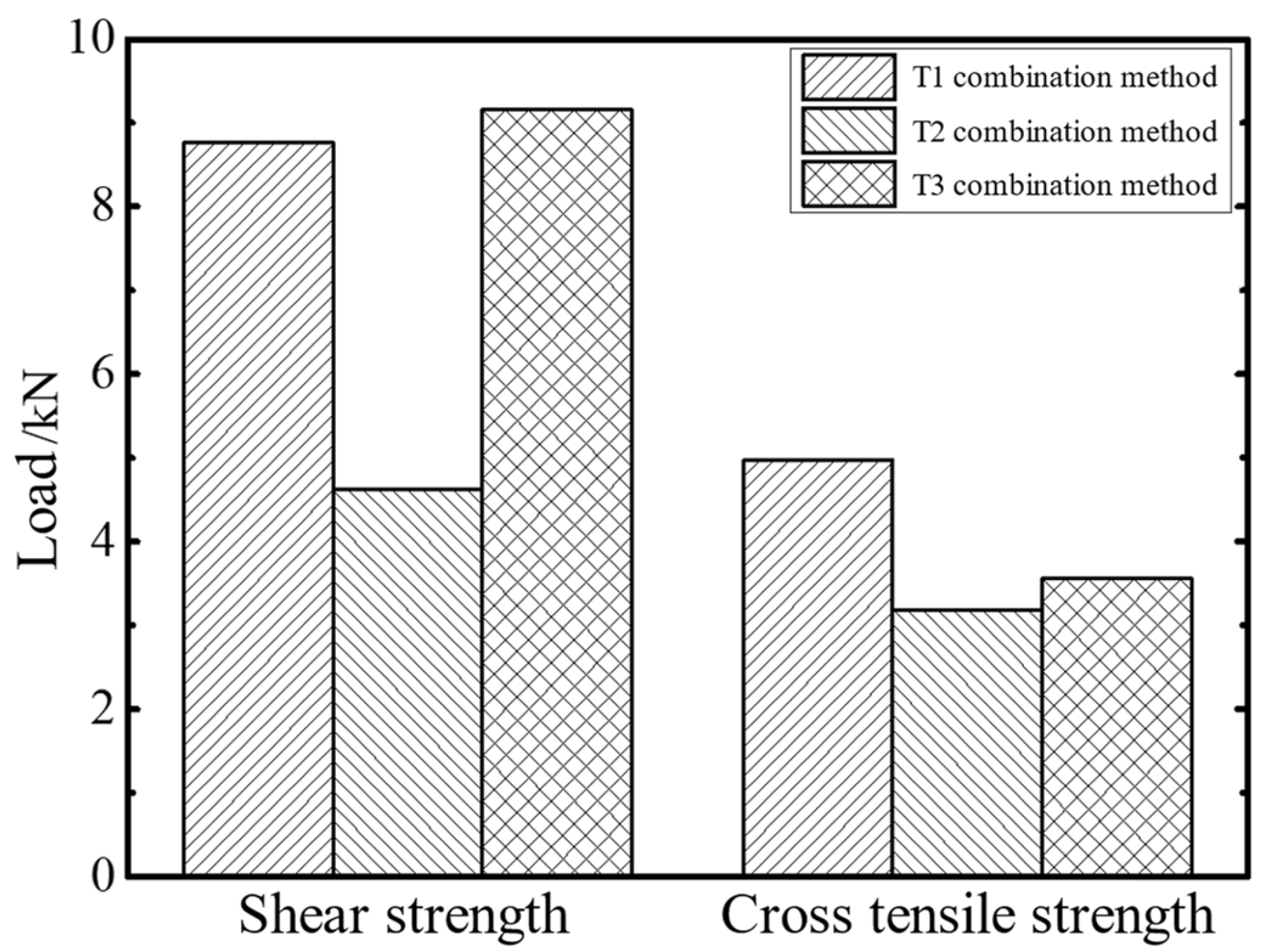
Figure 4.
Load-displacement curves of joints with different sheet-layer combination modes.
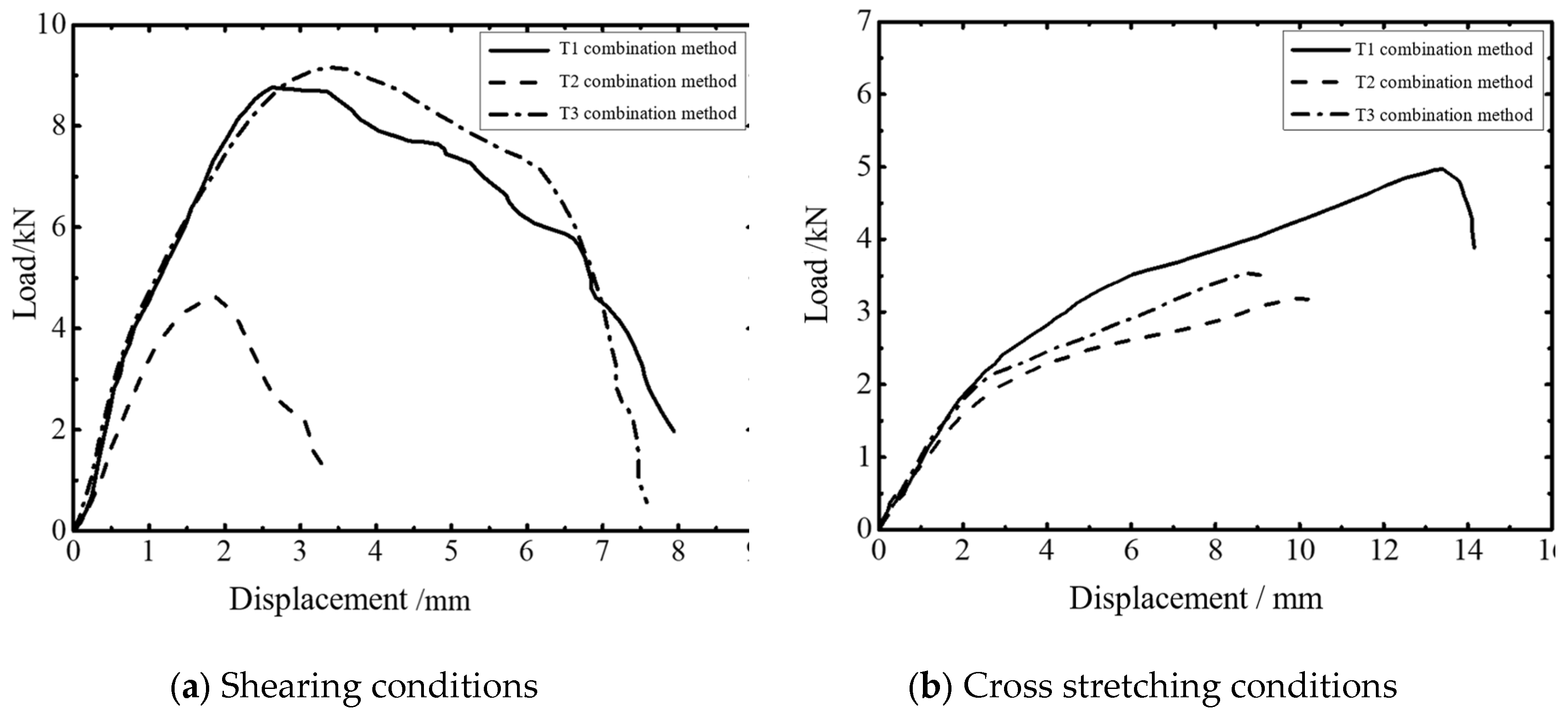
Figure 5.
Failure mode of joints with different sheet-layer combination modes under shear condition.
Figure 5.
Failure mode of joints with different sheet-layer combination modes under shear condition.
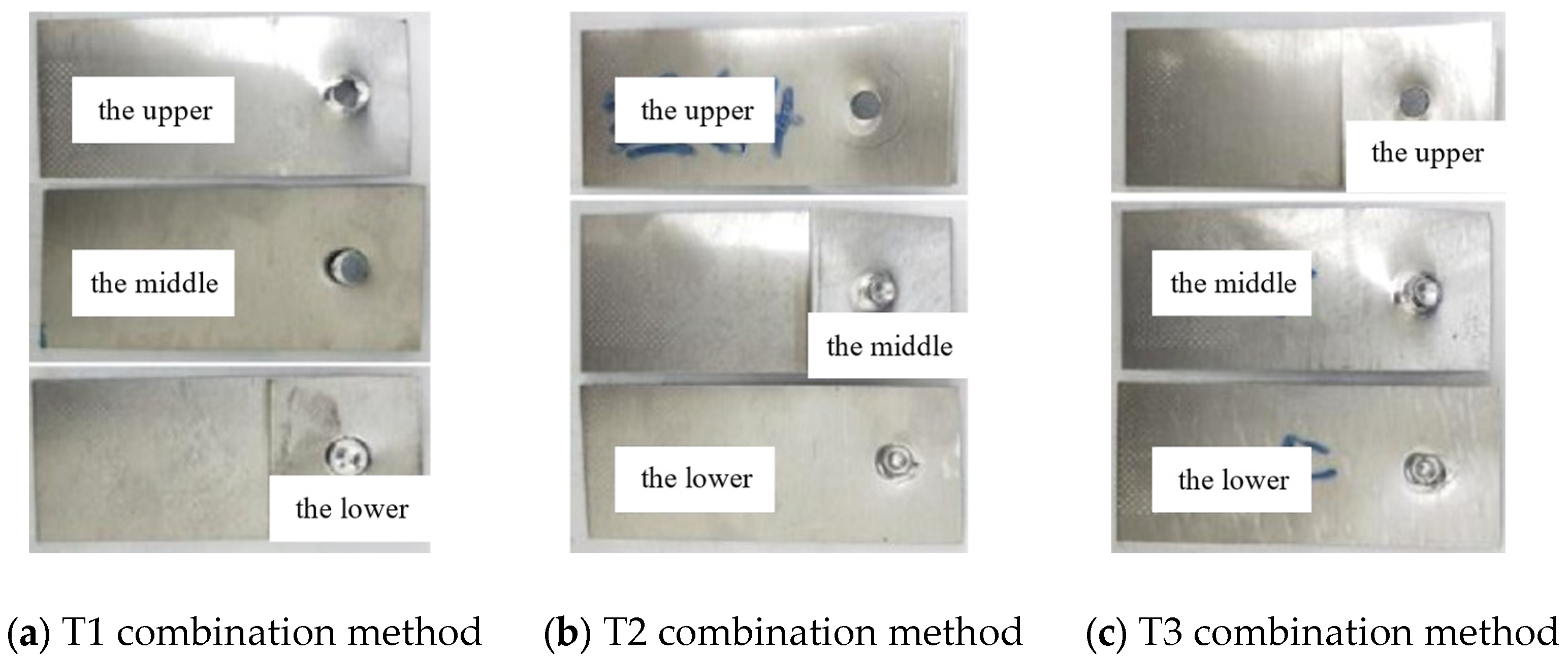
Figure 6.
Failure mode of joints with different sheet-layer combination modes under cross condition.
Figure 6.
Failure mode of joints with different sheet-layer combination modes under cross condition.
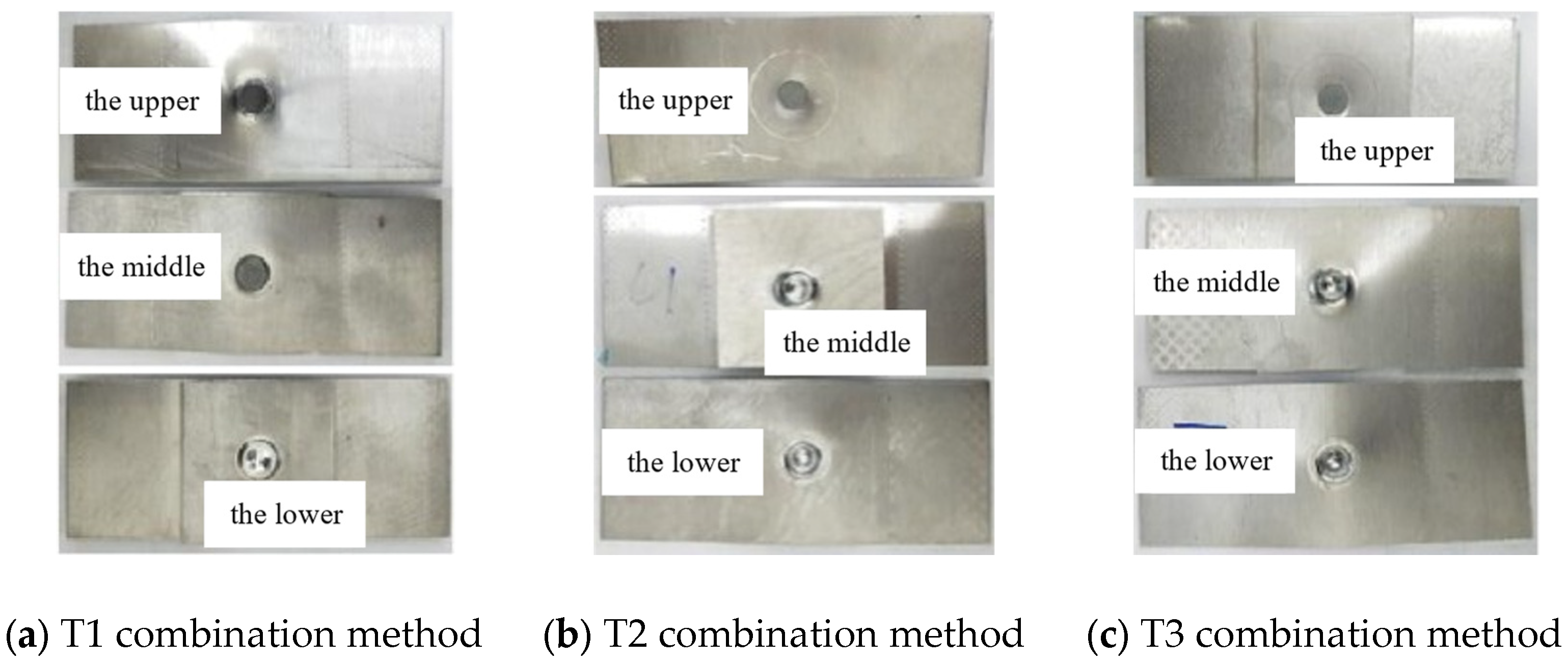
Figure 7.
Forming result of three-layers AA6063-T6 joint.
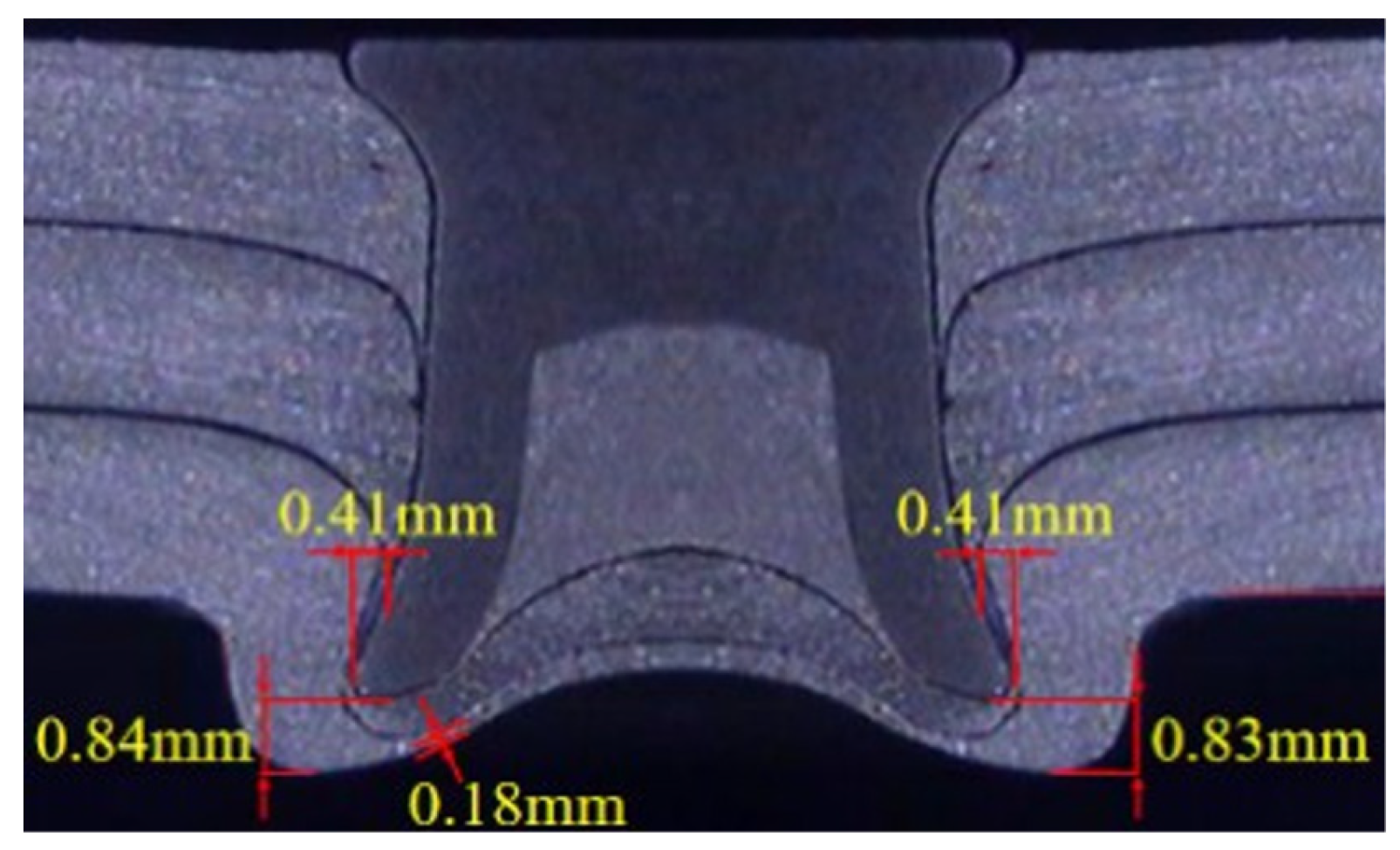
Figure 8.
Detail finite element model of joint.
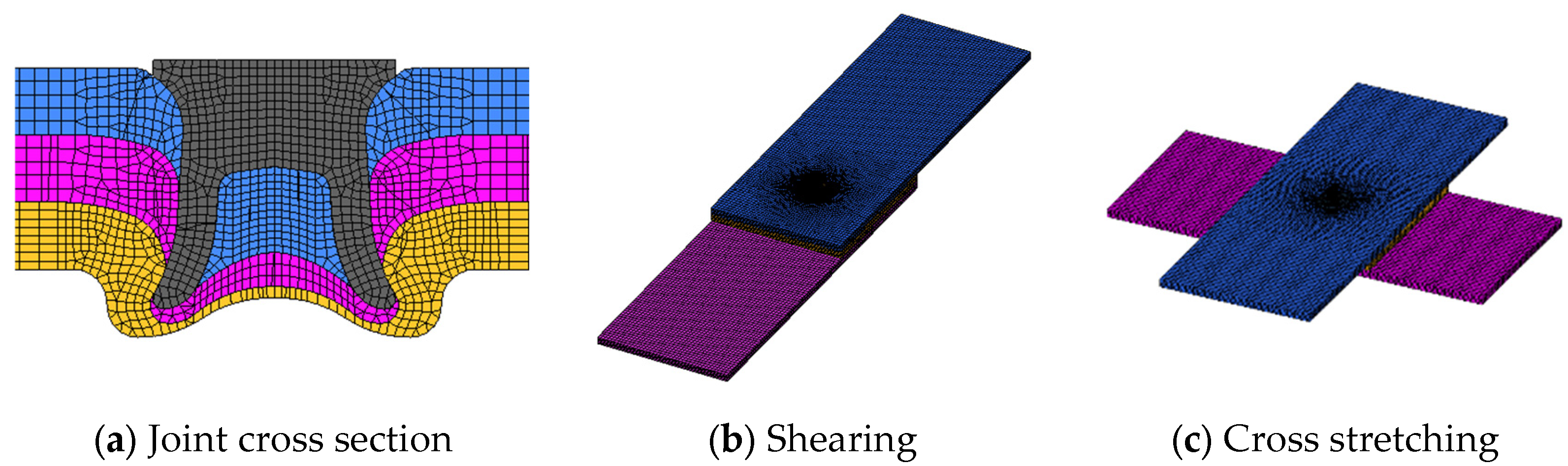
Figure 9.
Failure process of T1 joint under shear condition.
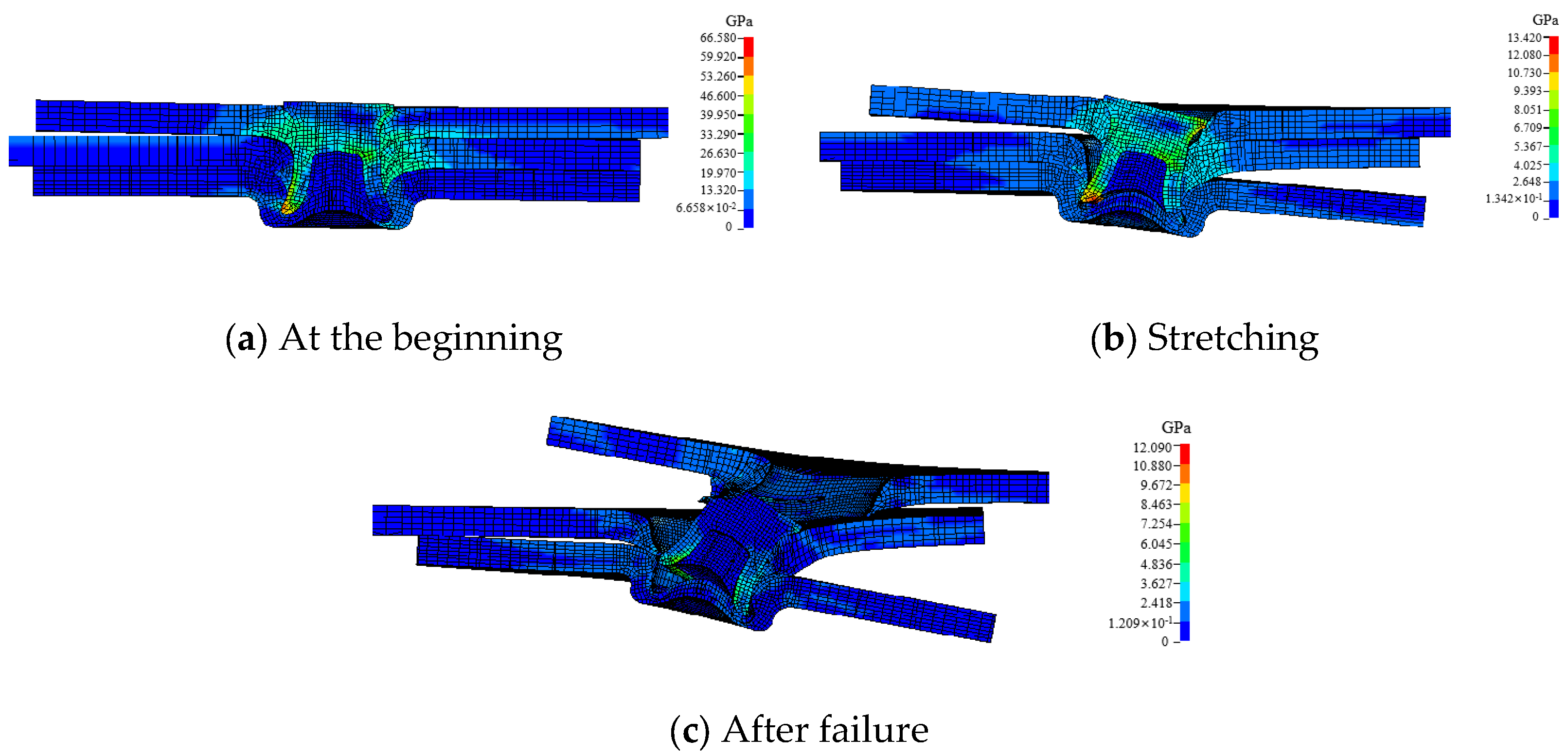
Figure 10.
Failure process of T1 joint under cross condition.
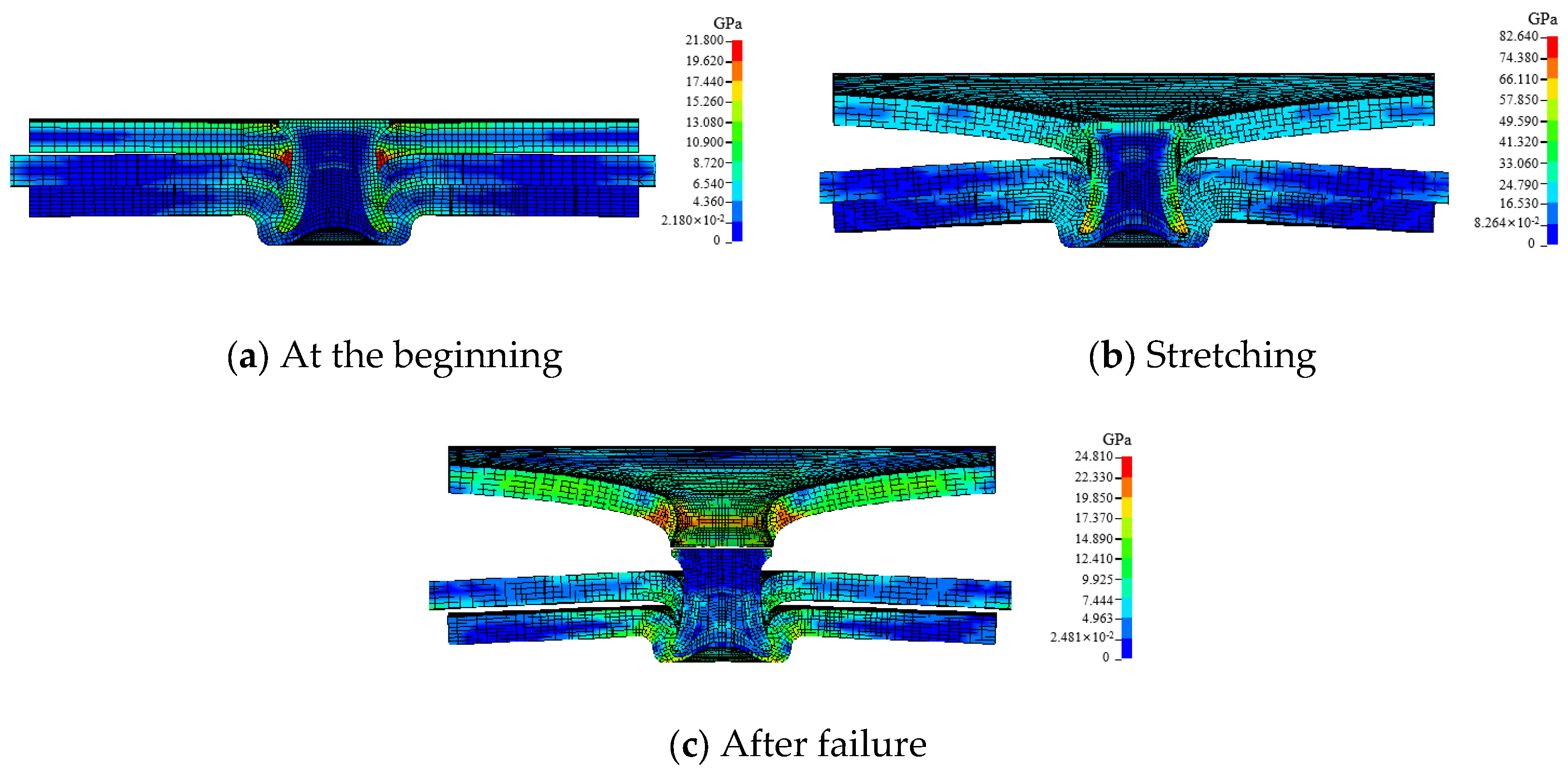
Figure 11.
Failure process of T2 joint under shear condition.
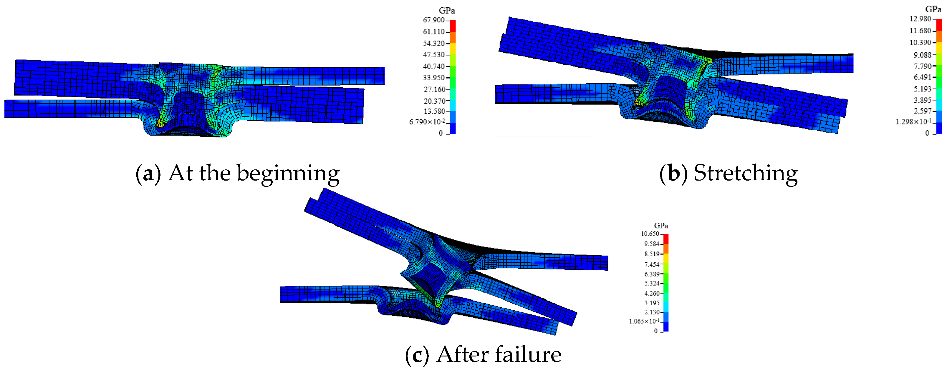
Figure 12.
Failure process of T2 joint under cross condition.
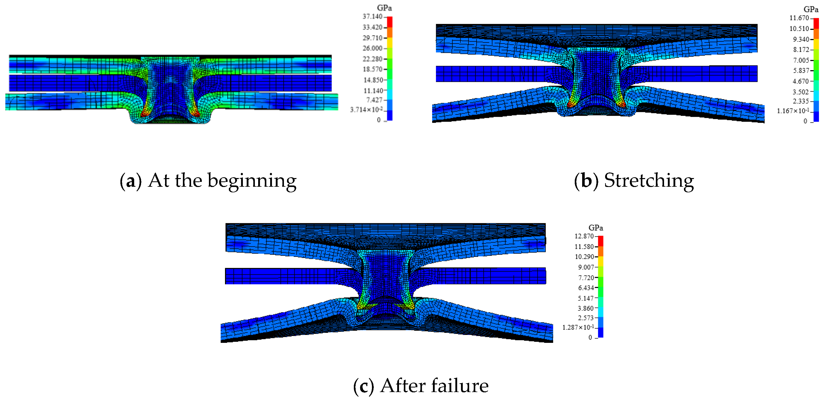
Figure 13.
Failure process of T3 joint under shear condition.
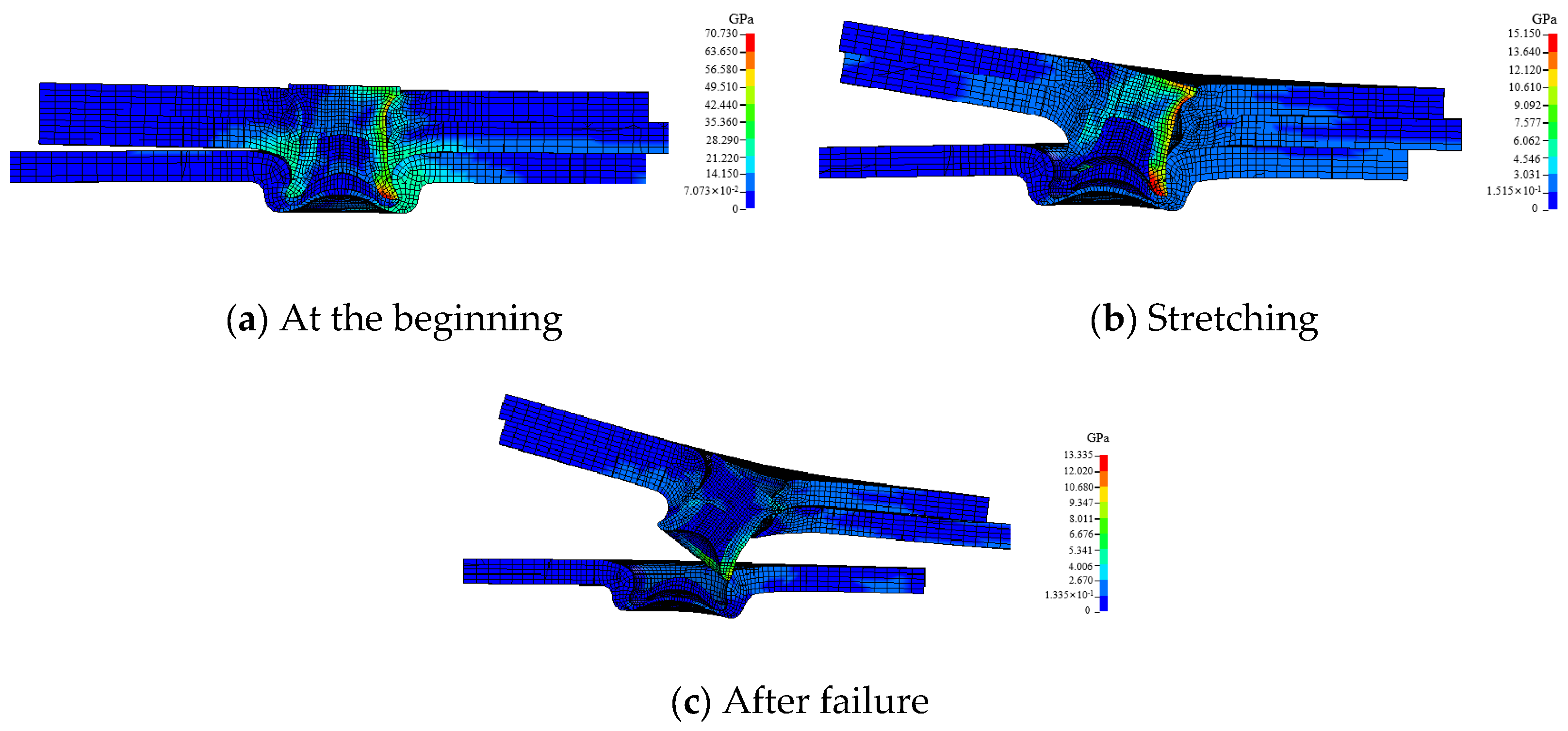
Figure 14.
Failure process of T3 joint under cross condition.
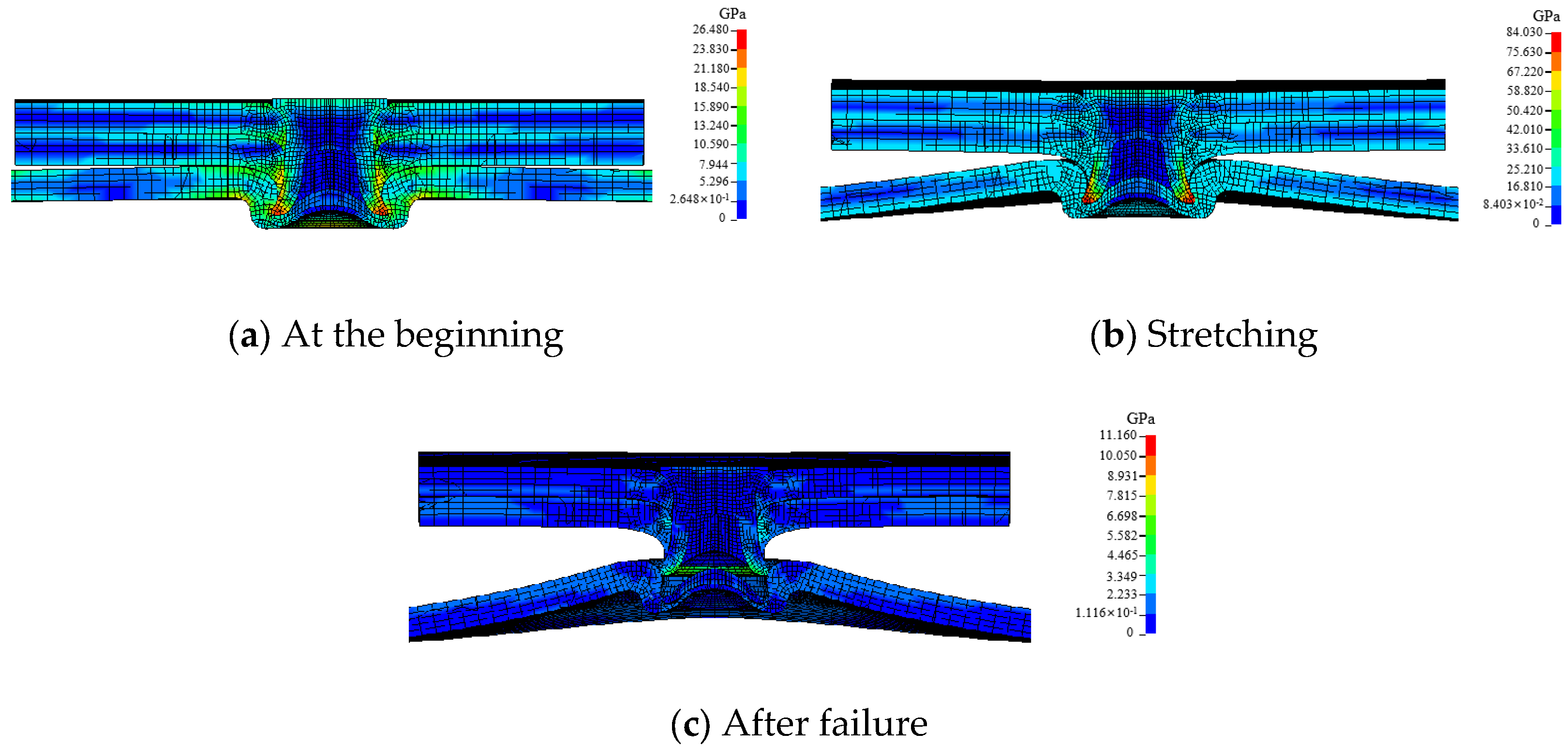

Table 1.
Material properties.
| Material | Density g/m3 |
Elastic modulus GPa |
Poisson’s Ratio | Yield Strength MPa |
|---|---|---|---|---|
| AA6063-T6 | 2.7 | 73 | 0.3 | 214 |
| rivet | 7.85 | 178.5 | 0.29 | 1515 |
Disclaimer/Publisher’s Note: The statements, opinions and data contained in all publications are solely those of the individual author(s) and contributor(s) and not of MDPI and/or the editor(s). MDPI and/or the editor(s) disclaim responsibility for any injury to people or property resulting from any ideas, methods, instructions or products referred to in the content. |
© 2025 by the authors. Licensee MDPI, Basel, Switzerland. This article is an open access article distributed under the terms and conditions of the Creative Commons Attribution (CC BY) license (http://creativecommons.org/licenses/by/4.0/).
Copyright: This open access article is published under a Creative Commons CC BY 4.0 license, which permit the free download, distribution, and reuse, provided that the author and preprint are cited in any reuse.


