Submitted:
13 February 2026
Posted:
14 February 2026
You are already at the latest version
Abstract
The main purpose of the paper is to show the possibility of assessing the dynamic properties of crankshaft in the early design phase of engine development, without performing dynamic forced response simulation. This is achieved by carrying out modal analysis of crankshaft under existing boundary conditions, namely by taking the radial stiffness in main bearings and the masses of moving conrods and pistons into account. The spectra of eigenfrequencies and corresponding mode shapes as a result of such supported modal analysis are compared to those of free modal analysis, emphasizing the influence of the boundary conditions. To easily identify the modes and to compare them with each other, kinetic energy-based method is used, alongside visualization and animation of mode shapes. The examples of crankshafts considered in the paper are taken from model catalog of virtual engines of six different sizes and configurations, being compared to that of in-line 4-cylinder engine as the reference case. All types of modal analysis are performed on structured FE models of crankshafts using software tool AVL EXCITE™ Shaft Modeler.
Keywords:
internal combustion engine
; crankshaft
; virtual model catalog
; AVL EXCITE
; CAD
; structured FE model
; modal analysis
; mode identification
1. Introduction
Despite the rapid advancement of battery electric vehicles (BEV), internal combustion engines (ICE) have not lost their relevance. There are two main reasons for that: 1) ICEs remain an integral part of hybrid electric vehicle (HEV) powertrains; 2) in the frame of decarbonization of emissions, ICEs running on alternative fuels (such as hydrogen, ammonia, and synthetic e-fuels) represent a viable option both from legislative and market viewpoints. Therefore, taking the mentioned trends into account, the research and development activities on ICEs continue. That creates broad innovation opportunities for research and engineering within the whole product life cycle of ICEs including design, simulation, testing and manufacturing.
In the early phase of ICE development, one of the design analysis tasks is the modal analysis of engine parts, especially of crankshaft.
The purpose of performing numerical modal analysis of free crankshaft is to verify the modal properties of its FE model against the real crankshaft by means of experiment like it was done in [2,3,4]. In addition to comparing the mode shapes visually, modal assurance criterion (MAC) was used in [2]. The influence of number of main journal master nodes on the spectrum of frequencies is studied in [4].
However, modal analysis of free crankshaft cannot predict its behavior within engine with sufficient accuracy. To achieve that, boundary conditions imposed by main bearings and moving masses of piston and conrod need to be taken into account. Just fixing the motion of the crankshaft in main bearings laterally would stiffen the system too much, unrealistically increasing its natural frequencies [5,6]; therefore, instead of constraining (fixing) the motion, one should add springs in two lateral directions [7].
In all the cases referenced above, crankshafts were modeled as volumetric FE models meshed using tetrahedral or hexahedral FE elements; the high number of nodes and elements in such meshes directly influences the performance of modal analysis. It is also difficult to distribute the radial stiffness of supporting bearings over the surface nodes of the journal FE mesh.
Visualization and animation of mode shapes are usually used to identify the mode type; in most cases textual designations (like “bending”, “torsion”, etc.) are used to characterize the type of deformations in modes, without quantifying them.
Being the most popular IC engine for passenger cars, in-line 4-cylinder 4-stroke (I4) engine and its crankshaft are most frequently analyzed, including the modal analysis. Concerning the modal properties of crankshafts of other engine types and configurations, these are studied e.g., in the following papers for: single-cylinder engine [8], 2-cylinder reciprocating compressor [9], three-cylinder gasoline engine [10], five-cylinder diesel engine [11], V10 engine [12]. There is no publication, however, in which the modal behavior of crankshafts of different engines types would be compared to each other.
In what follows, crankshafts of virtual models of six engines of different type, size, and application area are considered. Structured FE models of these crankshafts [1,13,14,15] are used to perform modal analysis of crankshafts with different boundary conditions and kinetic energy-based mode identification. The results of free and supported modal analyses are compared with each other. Differences and similarities in modal behavior of crankshafts of different engine types between each other and vs the reference case of in-line 4-cylinder are revealed and discussed.
2. CAD Models of Cranktrain Assemblies of Six IC Engines of Virtual Model Catalog
2.1. Cranktrains as CAD Model Assemblies
The following six virtual models of internal combustion (IC) engines are considered in the paper:
- a)
- V8_1: V-type 8-cylinder 6.0l racing car gasoline engine,
- b)
- I6: In-line 6-cylinder 10.0l heavy truck Diesel engine,
- c)
- I3: In-line 3-cylinder 0.8l small passenger car gasoline engine,
- d)
- V6: V-type 6-cylinder 4.0l large passenger car / van / SUV gasoline engine,
- e)
- V10: V-type 10-cylinder 5.0l racing car gasoline engine,
- f)
- V8_2: V-type 8-cylinder 3.2l light-truck Diesel engine.
The cranktrains of these virtual engines assembled from CAD models of engine parts (Figure 1) are kinematically animated using the 3D-View capabilities of AVL EXCITE™ Power Unit [16] to check for collision-free assembling, proper functioning and correct firing sequence of power cylinders.
Mass and inertia parameters of crankshafts, conrods and piston of all considered virtual engines are put into Table 1 for general reference, as well as for performing modal analysis and assessing its results. While the mass and inertia parameters listed in the table are exact values calculated according to geometric shape and mass density values of engine parts, the radial stiffness values in main bearings are estimated values based on engineering application experience for engines of respective type and scale.
3. From CAD to Structured FE Models of Crankshafts
3.1. Pre-Processed CAD Models of Crankshafts
On the way from CAD1 to structured model, the crankshafts considered in this paper are first pre-processed by AVL EXCITE™ AutoSHAFT, resulting in recognition and separation of the constituent parts of crankshafts like webs, main journals, crank pins, flywheel, pulley, etc., as shown in Figure 2 [1,14].
Depending on the engine type, number of cylinder and crank throws, as well as on size and functionality, one can recognize some specific geometric features of these crankshafts like: bolt-mounted counterweights (V8_1), webs with or without counterweights, webs with opposite or skew counterweights, webs with large banana-shaped counterweights, thin webs between two pins (V6), missing pulley or torsional vibration damper for racing-car crankshafts (V8_1 and V10).
3.2. Assembled Structured FE Models of Crankshafts
Assembled structured FE models of the crankshafts mentioned above are shown in Figure 3. The word “structured” underlines the existence of inner topology within such FE model that is manifested by beam-like elastic finite elements (represented by straight-line segments) connecting some pairs of nodes (small squares/dots).
After pre-processing step described in the previous paragraph, these structured FE models are generated using AVL EXCITE™ Shaft Modeler [17]. The theory behind the structured model of crankshaft, the methodology and procedure of its generation are described in more detail in [13,14].
While seeming visually simple compared to corresponding volumetric FE models, structured FE models represent the dynamic properties of the real crankshafts quite well, by appropriately approximating the mass/inertia and stiffness properties distributed in the volume. These dynamic properties have been verified by comparing the results of modal analysis and full dynamic forced response of structured FE model of crankshaft vs its volumetric FE model [13].
4. Theoretical Background of Modal Analysis of Crankshafts with Different Boundary Conditions and Kinetic Energy-Based Mode Identification
3.1. Modal Analysis with Different Boundary Conditions – Theory
Three types of modal analysis (MA) of crankshaft are considered in this paragraph. While the MA of free crankshaft results in its natural frequencies, the MA of supported crankshaft just gives an approximate estimation of its modal behavior within engine under simplifying conditions of constant mean values of stiffness in main bearings, as well as equivalent mass of conrod-piston assembly.
3.1.1. Modal Analysis of Free Crankshaft
To perform modal analysis of crankshaft, the eigenvalue problem expressed by a system of differential equations in time domain (1) can be transformed using the definition of periodic oscillatory function (2) into linear algebraic system in frequency domain (3) to solve it in terms of angular eigenfrequency and eigenvector :
A structured model of crankshaft having N nodes possesses 6N degrees of freedom, which define the order of the mentioned system of linear algebraic equations (3), with and being the mass and stiffness matrices of the free crankshaft.
As a solution of equations (3), we get 6N modes, each one characterized by its angular eigenfrequency and eigenvector . In engineering practice, however, it is usual to operate with natural frequency :
For free crankshaft, the first six natural frequencies are all zero, corresponding to six rigid-body modes representing the six DOFs of a rigid body.
Combining eigenvector with geometric configuration of crankshaft nodes results in its mode shape.
The spectrum of natural frequencies and corresponding mode shapes fully characterize the dynamic vibratory behavior of the free crankshaft.
3.1.2. Modal Analysis of Crankshaft Supported by Main Bearings
Within the engine, however, the crankshaft is not free, being subject to some boundary conditions: each main journal of the rotating crankshaft is in sliding contact over cylindrical surface with the main bearing shell, and the radial stiffness of this contact should be taken into account to assess the dynamic properties of the supported crankshaft.
To do that, the parts of the stiffness matrix of crankshaft related to main journal nodes should be modified according to the scheme shown in Figure 4. Here, for the crankshaft with rotation axis x, the main bearing radial stiffness coefficient is distributed among the nodes of main journal and added to diagonal elements of the stiffness matrix standing for lateral translational DOFs y and z.
3.1.3. Modal Analysis of Supported Crankshaft with Added Masses
To come closer to the real conditions of crankshaft within engine, masses of conrod and piston should also be taken into account.
The big end bearing of each conrod is in sliding contact with the corresponding crank pin of the rotating crankshaft. To take the moving masses of conrod and piston into account while performing the modal analysis of crankshaft, equivalent additional mass is calculated for each engine cylinder according to the following formula [12,18,19,20]:
where the rotational mass is the conrod mass at big end, and the oscillating mass is the sum of the masses of piston, piston pin, and the conrod at small end. The mass of conrod at intermediate point (in case of 3-point model of conrod) is distributed between big and small ends of conrod.
Finally, the parts of the mass matrix of crankshaft related to crank pin nodes are modified according to the scheme shown in Figure 5. Here, for the crankshaft with rotation axis x, additional mass is distributed among the nodes of a crank pin and added to diagonal elements of the mass matrix standing for lateral translational DOFs y and z.
3.2. Mode Identification Based on Kinetic Energy
To identify any mode in each of the types of modal analysis described above, we use the approach based on kinetic energy. As the linear system (3) is freely scalable, we can interpret its solutions as velocities instead of displacements by differentiating equation (2) in time :
After that, we define the kinetic energy of oscillatory motion components (torsion, tension, and bending) for the subset of nodes lying on rotation axis (in our case – coordinate axis x) as follows (7)-(9):
Summing up the last three equations to total kinetic energy of the motion of the subset of nodes
one can determine the percentage of kinetic energy of oscillatory motion for each of its components (torsion, tension, and bending):
5. Reference Case: Modal Analysis of I4 Engine Crankshaft
5.1. CAD and Structured FE Models of I4 Engine Crankshaft
5.2. Modal Analysis of I4 Engine Crankshaft
In all of the following tables of natural frequencies, only the first six elastic modes are listed, while the leading rigid-body modes of zero frequency (i.e., the 1st-6th for free crankshafts, and the 1st and 2nd – for supported crankshafts) are skipped.
Natural frequencies of the crankshaft as a result of modal analysis with different boundary conditions are listed in Table 2. In case of supported crankshaft, the values for stiffness coefficients and additional masses are those taken from Table 1.
The mode shape of mode 7 highlighted in Table 2 (a) is shown in Figure 8. This free mode is almost purely bending one, like the other two modes 8 and 12, too. Mode 9 is purely torsional. Mode 10 is bending dominated with some portion of tension, while tension dominated mode 11 has a portion of bending in it.
In case of supported crankshaft, the natural frequencies of the first two bending modes increase strongly (1.5x…2x) because of the radial stiffness in main bearings, while mostly preserving a similar mode shape: thus, the first two free bending modes 7 and 8 of Table 2 (a) become bending modes 4 and 5 in Table 2 (b), with a bit more tension components added. On the contrary, the frequency of free torsion mode 9 of Table 2 (a) increases only slightly (< 2%) becoming the first elastic mode 3 in the list of supported modes in Table 2 (b). The frequency of tension dominated mode 11 (Table 2, a) considerably increases because of the boundary conditions, becoming supported mode 8 (Table 2, b).
6. Modal Analysis Examples from Virtual Model Catalog
6.1. Case 1: Modal Analysis of Crankshaft of V8_1 Engine
Natural frequencies of the crankshaft as a result of modal analysis with different boundary conditions are listed in Table 3.
The mode shape of mode 8 highlighted in Table 3 (a) is shown in Figure 9. This free mode is almost purely bending one, like other two modes 7 and 10. Torsion-dominated free mode 11 contains a considerably high portion of bending motion, while modes 9 and 12 consists of nearly equal shares of bending and tension.
In case of supported crankshaft, the natural frequencies of the first two bending modes increase strongly (~3x) moving down the list – from mode 7 and 8 of Table 3 (a) to modes 6 and 5 – with permutation – in Table 3 (b), getting some more tension components (~13%) of motion added. On the contrary, the frequency of torsion-dominated free mode 11 of Table 3 (a) increases only slightly (~5%) moving up the list to mode 4, with torsion dominance becoming stronger (Table 2, b). Similarly, the tension domination of mode 9 (Table 3, a) becomes more pronounced as mode 3 (Table 2, b), with moderate increase in frequency (~ 27%).
3.2. Case 2: Modal Analysis of Crankshaft of I6 Engine
Natural frequencies of the crankshaft as a result of modal analysis with different boundary conditions are listed in Table 4.
The mode shape of mode 12 highlighted in Table 4 (a) is shown in Figure 10. This free mode is a tension dominated one, with considerably high portion of bending motion. Mode 11 is very strongly torsion dominated, and the first two modes 7 and 8 are nearly pure bending ones, while the next two modes 9 and 10 are bending dominated.
In case of supported crankshaft, the natural frequencies of all the modes increase; in Table 4 (b) one can see now bending modes with considerable torsional (modes 4, 5 and 8) or tensional (modes 3 and 7) content. The highlighted mode 6 becomes stronger tension dominated, with an increased frequency (+35%).
Additional masses of conrod and piston according to equation (5) and Table 1 slightly decrease all the frequencies. For many of the modes, this is accompanied by considerable re-distribution of motion component shares, except for tension dominated mode 6 and bending dominated mode 7, with the mode shapes remaining practically unchanged – compare Table 4 (c) with Table 4 (b).
3.3. Case 3: Modal Analysis of Crankshaft of I3 Engine
Natural frequencies of the crankshaft as a result of modal analysis with different boundary conditions are listed in Table 5.
The mode shape of mode 9 highlighted in Table 5 (a) is shown in Figure 11. This free mode is a mixed one, with nearly equal shares of tensional and bending motion, and less share of torsional motion. The free modes 7, 8 and 11 are almost purely bending ones. Torsion-dominated free mode 10 contains some small portions (~10%) of tension and bending motions each.
In case of supported crankshaft, the mixed mode becomes tension dominant, with ~1.7x increased frequency (see mode 8 highlighted in Table 5, b). The first two bending modes practically remain purely bending ones, with about ~25% increased frequency. Torsion dominated mode 10 (Table 5, a) gets more bending added to it, with frequency just slightly increased (~2%).
3.4. Case 4: Modal Analysis of Crankshaft of V6 Engine
Natural frequencies of the crankshaft as a result of modal analysis with different boundary conditions are listed in Table 6.
The mode shape of mode 9 highlighted in Table 6 (a) is shown in Figure 12. This free mode is very strongly torsion dominated. Modes 7 and 8 are nearly pure bending modes.
In case of supported crankshaft, the frequency of mode 9 of Table 6 (a) increases only slightly (~3%) moving up the list to mode 3, with the mode shape getting more bending share (Table 6, b).
3.5. Case 5: Modal Analysis of Crankshaft of V10 Engine
Natural frequencies of the crankshaft as a result of modal analysis with different boundary conditions are listed in Table 7.
The mode shape of mode 9 highlighted in Table 7 (a) is shown in Figure 13. This is a bending-dominated mode, that – like mode 11 – contains a considerable portion of tension motion (~25%). The first two free modes 7 and 8 are almost purely bending ones, while the other bending-dominated modes contain a substantial portion (>40%) of torsional (mode 10) or tensional (mode 12) component.
In case of supported crankshaft, the natural frequencies of the first two bending modes increase strongly (~4x) moving down the list – from mode 7 and 8 of Table 7 (a) to modes 5 and 6 in Table 7 (b), with a bit more tension components (up to 9%) of motion added. In mode 10, torsion becomes dominant, moving it to the first position as mode 3 (Table 7, b). In mode 12, tension becomes dominant, moving it to the second position as mode 4.
3.6. Case 6: Modal Analysis of Crankshaft of V8_2 Engine
Natural frequencies of the crankshaft as a result of modal analysis with different boundary conditions are listed in Table 8.
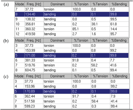
The mode shape of mode 8 highlighted in Table 8 (a) is shown in Figure 14. This free mode is almost purely bending one, like other two modes 9 and 12. The first free elastic mode 7 is a purely torsional one. Bending-dominated mode 10 contains a high portion of tensional motion, while torsion-dominated mode 11 contains a considerable portion of bending motion.
Moving from free to supported modal analysis, the frequency of torsional mode remain unchanged. The frequencies of the first two bending modes 8 and 9 of Table 8 (a) moderately increase (27% and 11%) while interchanging their places in the list and becoming mode 5 and 4 in Table 8 (b), respectively. In the bending-dominated mode 10 with tension, the tension share increases becoming dominant (mode 7 in Table 8, b). The frequency of torsion-dominated free mode 11 (Table 8, a) increases only slightly (~6%) moving up the list, with torsion dominance becoming stronger (mode 6 in Table 8, b). For mode 12, the bending component increases, with considerable frequency increase (~ 44%).
7. Discussion: Comparing the Results Between Models of Virtual Model Catalog and the Reference Case
Considering the modal behavior of I4 engine crankshaft (reference case, see Section 5), we observe an extremely high grade of purity (> 99%) of the first free modes – the first two bending modes and the first torsional mode. In case of supported crankshaft, these modes still keep a high grade of purity (> 95%). The frequency of the bending modes strongly increases due to tight boundary conditions in the main bearings, while the frequency of the first torsion mode increases only slightly (< 2%). Additional masses of conrod and piston have nearly no influence on the frequencies and mode shapes of the first three modes.
All the mentioned behavior patterns are due to plane symmetry of the crankshaft of I4 engine, sufficiently large masses and moments of inertia of flywheel and pulley, high radial stiffness in main bearings, and relatively small masses of pistons and conrods.
Considering now the results of modal analysis of the other crankshafts (Section 6) and comparing them with each other and with the reference case of I4 engine crankshaft, one can observe the following:
- 1)
-
For the modal analysis of free crankshafts:
- The first two bending dominated “half-wave” shaped modes are pure in all cases (> 99% of bending content).
- The first torsional mode for crankshafts with point-symmetric geometry and throws lying in parallel of perpendicular planes (V8, with angles ±90° or 180° between throws) is only pure in case of high moments of inertia of flywheel and pulley, like in case of V8_2 engine. For crankshafts I3, I6, V6 with regular “helical” arrangement of crank throws (with 120° between the planes of neighbor throws), the first torsion-dominated mode is not pure. For crankshafts V10 with thin flywheel and no pulley and with irregular arrangement of crank throws (with 144° or 72° between planes of neighbor throws), no torsion-dominated mode can be seen in this part of spectrum, and a substantial portion of torsion is present in bending-dominated modes only.
- A tension-dominated mode is never pure , being mostly coupled with high percentage of bending component, and eventually a small portion of torsion.
- 2)
-
For the modal analysis of supported crankshafts:
- For V8 engine crankshafts, the torsional modes remain purely torsional only if the masses of flywheel and pulley are large enough, as in V8_2 case, and show a tendency to increase the torsional component in torsion-dominated modes, as in V8_1 case. On the contrary, crankshafts I3, I6, V6 show a tendency for torsion-dominated modes to decrease the share of torsional component. For V10 crankshaft, a strongly torsion-dominant mode just appears in the list.
- The bending modes remain purely bending only if the masses of flywheel and pulley are large enough (I3, V8_2), otherwise the percentage of tensional (V8_1, V10), torsional (I6), or of both (V6) tensional and torsional components increase.
- Tension-dominated modes become either more pronounced or transformed from bending-dominated ones (V8_1, I6, I3, V8_2), as well as appear (V10) or disappear (V6).
- Similar to the reference case (I4), additional masses of conrod and piston slightly decrease all the frequencies – this is clearly influenced by the masses of piston and conrod and the number of cylinders in relation to the mass of the crankshaft, as well as masses of flywheel and pulley.
8. Conclusions and Outlook
Crankshafts of seven different engine types and sizes are considered. With AVL EXCITE™ simulation tools, CAD models of these crankshafts are transformed into structured FE models used in the investigation.
The theory behind modal analysis of a crankshaft supported in main bearings, under the influence of piston and conrod masses, is described. Kinetic energy-based mode identification method is introduced.
Modal analysis of supported crankshafts is performed, and the results – natural frequencies and eigenmodes – are compared to those of free crankshafts. Modal behavior patterns of different crankshafts are revealed based on visualized mode shapes, as well as on percentages of three basic motion components present in each of the modes: torsion, bending, and tension.
While not meant to substitute the full dynamic analysis, the supported modal analysis with mode shape identification can help understand the vibratory behavior of crankshafts within engine in the early phase of developing new engine or during a check of existing one.
The future work will focus on considering the models mentioned in the paper to perform further tasks of design analysis of IC engines based on simulation of their dynamics.
The authors welcome feedback on this work and are open to collaboration.
Author Contributions
Theory and methodology, software implementation (calculation kernel of AVL EXCITE™ Shaft Modeler), project coordination, investigation, writing, Tigran Parikyan; creating CAD of the crankshafts and other engine parts for virtual model catalog, Davit G. Yurmuzyan; generating structured FE models of crankshafts from CAD using AVL EXCITE™ pre-processors AutoSHAFT and Shaft Modeler, Arpine S. Babayan; project supervision and administration, Feliks H. Parikyan. All authors have read and agreed to the published version of the manuscript.
Funding
The two original projects to create virtual model catalogs for crankshafts and later – cranktrains, for use with AVL EXCITE™ Power Unit & Designer were funded by the Advanced Simulation Technologies of AVL List GmbH (Graz, Austria) and were carried out at the State Engineering University of Armenia2 in the years 2008-2010. The funders had no role in the design of the present study; in the collection, analyses, or interpretation of data; in the writing of the manuscript; or in the decision to publish the results.
Acknowledgments
The first author would like to thank his AVL colleagues: Thomas Resch – for the definition of configurations, functional purposes and size ranges of engines for virtual model catalog, and Christoph Schweiger – for fruitful discussions concerning the preparation of CAD models of engine parts. The implementation of the functionality of AVL EXCITE™ simulation tools – Shaft Modeler (GUI and post-processing) by Josip Juric, and AutoSHAFT (calculation kernel) by Goran Todorovic (AVL-AST d.o.o., Croatia) – is gratefully acknowledged.
Conflicts of Interest
The authors declare no conflicts of interest.:
Abbreviations
The following abbreviations are used in this manuscript:
| BEV | Battery electric vehicle |
| CAD | Computer-aided design |
| DOF | Degree of freedom |
| FE | Finite element |
| HEV | Hybrid electric vehicle |
| IC | Internal combustion |
| ICE | Internal combustion engine |
| MA | Modal analysis |
| MAC | Modal assurance criterion |
Nomenclature
The following nomenclature is used in the paper:
| total number of nodes of crankshaft | |
| number of subset of nodes of crankshaft lying on rotation axis | |
| natural angular frequency of mode [rad/s] | |
| natural frequency of mode [Hz] | |
| eigenvector of mode (in terms of displacements) | |
| eigenvector of mode (in terms of velocities) | |
| periodic function associated with eigenvector of mode | |
| mass and stiffness matrices of the system | |
| radial stiffness in main bearing | |
| additional mass taking the moving masses of piston and conrod into account | |
| rotational mass of conrod | |
| oscillating mass of conrod and piston | |
| mass of the ith node lying on rotation axis | |
| moments of inertia of the ith node about axes x, y and z | |
| three translational velocity components of eigenvector for ith node | |
| three angular velocity components of eigenvector for ith node | |
| torsional component of kinetic energy of an eigenmode | |
| tensional component of kinetic energy of an eigenmode | |
| bending component of kinetic energy of an eigenmode | |
| total kinetic energy of an eigenmode | |
| 1 | In STL format. |
| 2 | Former name of the National Polytechnic University of Armenia. |
References
- Parikyan, T., Yurmuzyan, D.G., Babayan, A.S., Parikyan, F.H. (2026). Cranktrain Model Catalog as a Didactic Tool for Generating Structured Models of Engine Parts to be Used in Dynamic Simulation with AVL EXCITE™. In: Parikyan, T., Sargsyan, Y., Ceccarelli, M. (eds) Mechanical Engineering Solutions: Design, Simulation, Testing, Manufacturing. MES 2025. Mechanisms and Machine Science, vol 191. Springer, Cham. [CrossRef]
- Sani M. S. M., Noor M. M., Zainury M. S. M., Rejab M. R. M., Kadirgama K., and Rahman M. M. (2010), Investigation on modal transient response analysis of engine crankshaft structure, WIT Transactions on The Built Environment, High Performance Structures and Materials V, Vol 112, p. 419-428. [CrossRef]
- Azoury, C., Kallassy, A., Combes, B., Moukarzel, I., Boudet, R.: Experimental and analytical modal analysis of a crankshaft. IOSR J. Eng. 2(4), 674–684, ISSN 2250-3021 (2012).
- Tian, Z.; Sun, Z.; Zhou, Y.; Zhou, Y. Research on Numerical Calculation Methods for Modelling the Dynamics of Diesel Engine Crankshaft System Substructures. Appl. Sci. 2025, 15, 5551. [CrossRef]
- Yadav S. K. , Wadkar S. B., Patil S. J., Modal Analysis of Compressor Crankshaft, International Journal of Scientific Research (2013) JSR 2(7):155-158. [CrossRef]
- Zheng, B., Zhang, J., Lei, J., Crankshaft Optimization Based on Experimental Design and Response Surface Method, Mathematical Problems in Engineering, 2022, Wiley Online Library, 15 pages, 2022. [CrossRef]
- Yu, B.; Yu, X.; and Feng, Q., "Simple Modeling and Modal Analysis of Reciprocating Compressor Crankshaft System" (2010). International Compressor Engineering Conference. Paper 1982. https://docs.lib.purdue.edu/icec/1982.
- Zheng B., Liu Y., Liu R., Meng J., 3D Finite Element Analysis of Single-Cylinder Diesel Engine Crankshaft, Applied Mechanics and Materials, 182–183, pp. 1654–1658, 2012. [CrossRef]
- Mu G., Wang F., Mi X. Static Strength and Modal Analysis of Crankshaft of a High-Speed Reciprocating Compressor. Proc. MMECEB-15, 641–645 (2015). [CrossRef]
- Zhang, X.; Zheng, L. Investigation on the Dynamics of a Flexible Multi-Body System of a Three-Cylinder Gasoline Engine Crankshaft. Processes 2023, 11, 1248. [CrossRef]
- Zhao B. Finite Element Model Analysis on Five-Cylinder Marine Diesel’s Crankshaft Based on UG and ANSYS. Adv. Mater. Res. 538-541, 677–681 (2012). [CrossRef]
- Kimura, J., Okamura, H., and Sogabe, K., "Experiments and Computation of Crankshaft Three-Dimensional Vibrations and Bending Stresses in a Vee-Type Ten-Cylinder Engine," SAE Technical Paper 951291, 1995. [CrossRef]
- Parikyan, T., Resch, T., & Priebsch, H. H. "Structured Model of Crankshaft in the Simulation of Engine Dynamics With AVL/EXCITE." Proceedings of the ASME 2001 Internal Combustion Engine Division Fall Technical Conference. Volume 3: Engine Systems: Lubrication, Components, Exhaust and Boosting, System Design and Simulation. Argonne, Illinois, USA. September 23–26, 2001. p. 105-114. ASME. [CrossRef]
- Todorovic, G. and Parikyan, T., “Automated Generation of Crankshaft Dynamic Model to Reduce Engine Development Time,” SAE Paper No. 2003-01-0926 (2003). [CrossRef]
- Parikyan, T., “Efficient Modeling of Engine Parts and Design Analysis Tasks in Simulation of Powertrain Dynamics: An Overview”. In: Parikyan, T. (eds) Advances in Engine and Powertrain Research and Technology. Mechanisms and Machine Science, vol 114, Springer (2022). [CrossRef]
- AVL EXCITE™ Power Unit — Software package for durability and NVH of power units and drivelines, Theory and User Manuals. AVL List GmbH. Version 2025 R1.
- AVL EXCITE™ Shaft Modeler with AutoSHAFT—CAD-FEM Pre-processor to generate dynamic structured models of crankshafts and other shafts, User Manual. AVL List GmbH. Version 2025 R1.
- Okamura, H., Sogabe, K., Sato, Y., Suzuki, Y. et al., "Experiments on the Coupling and Transmission Behavior of Crankshaft Torsional Bending and Longitudinal Vibrations in High Speed Engines," SAE Technical Paper 830882, 1983. [CrossRef]
- Rajendran, S., and Narasimhan, M. V. (January 1, 1997). "Effect of Inertia Variation Due to Reciprocating Parts and Connecting Rod on Coupled Free Vibration of Crankshaft." ASME. J. Eng. Gas Turbines Power. January 1997; 119(1): 257–263. [CrossRef]
- Shabana A.A. Dynamics of Multibody Systems. 4th ed. Cambridge University Press; 2013.
Figure 1.
CAD-based virtual models of cranktrains of six distinct types of IC engines, visualized and animated using AVL EXCITE™ [1]: (a) V8_1; (b) I6; (c) I3; (d) V6; (e) V10; (f) V8_2.
Figure 1.
CAD-based virtual models of cranktrains of six distinct types of IC engines, visualized and animated using AVL EXCITE™ [1]: (a) V8_1; (b) I6; (c) I3; (d) V6; (e) V10; (f) V8_2.
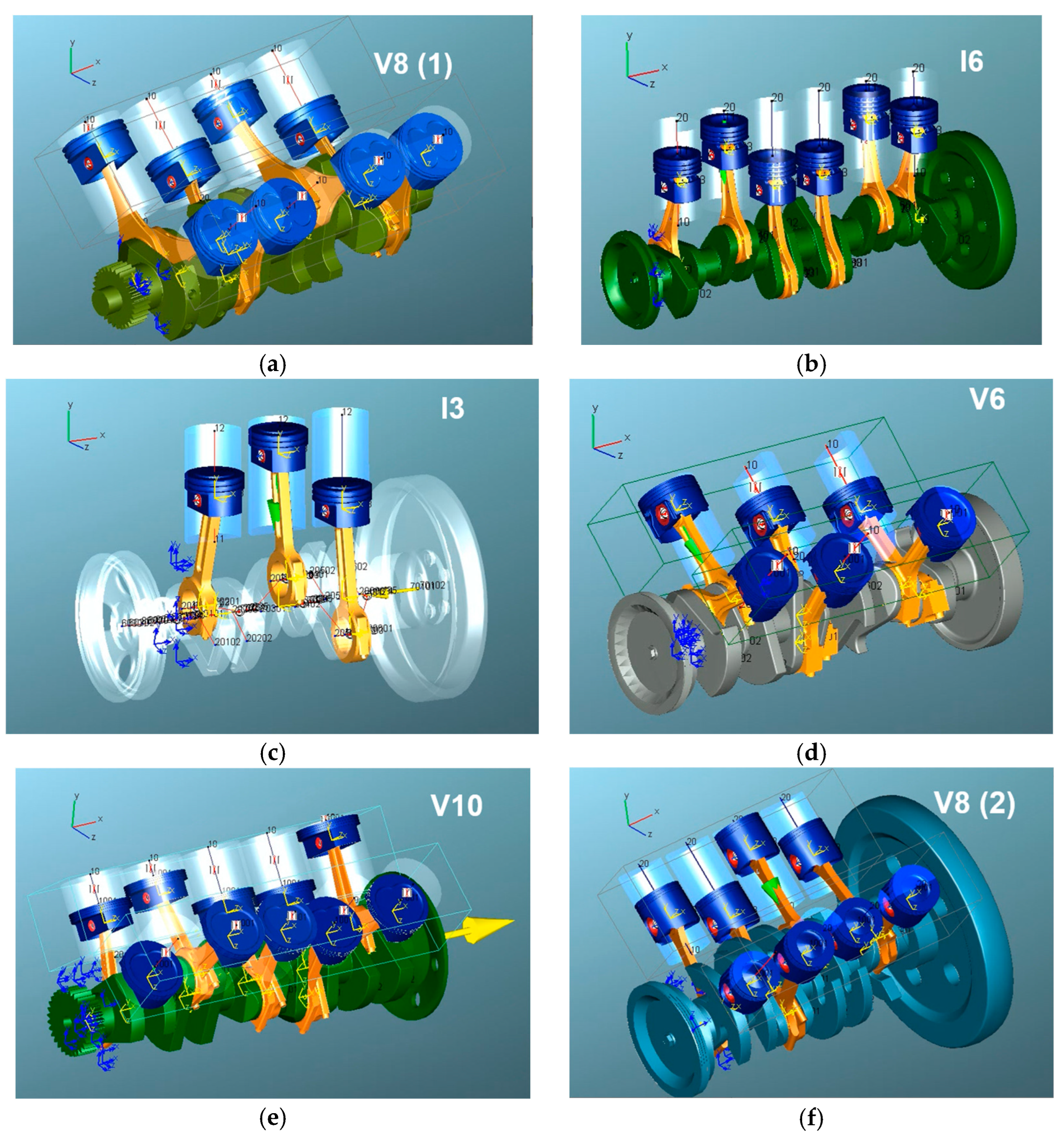
Figure 2.
CAD models of crankshafts of the following engines, pre-processed by AVL EXCITE™ AutoSHAFT [1]: (a) V8_1; (b) I6; (c) I3; (d) V6; (e) V10; (f) V8_2.
Figure 2.
CAD models of crankshafts of the following engines, pre-processed by AVL EXCITE™ AutoSHAFT [1]: (a) V8_1; (b) I6; (c) I3; (d) V6; (e) V10; (f) V8_2.
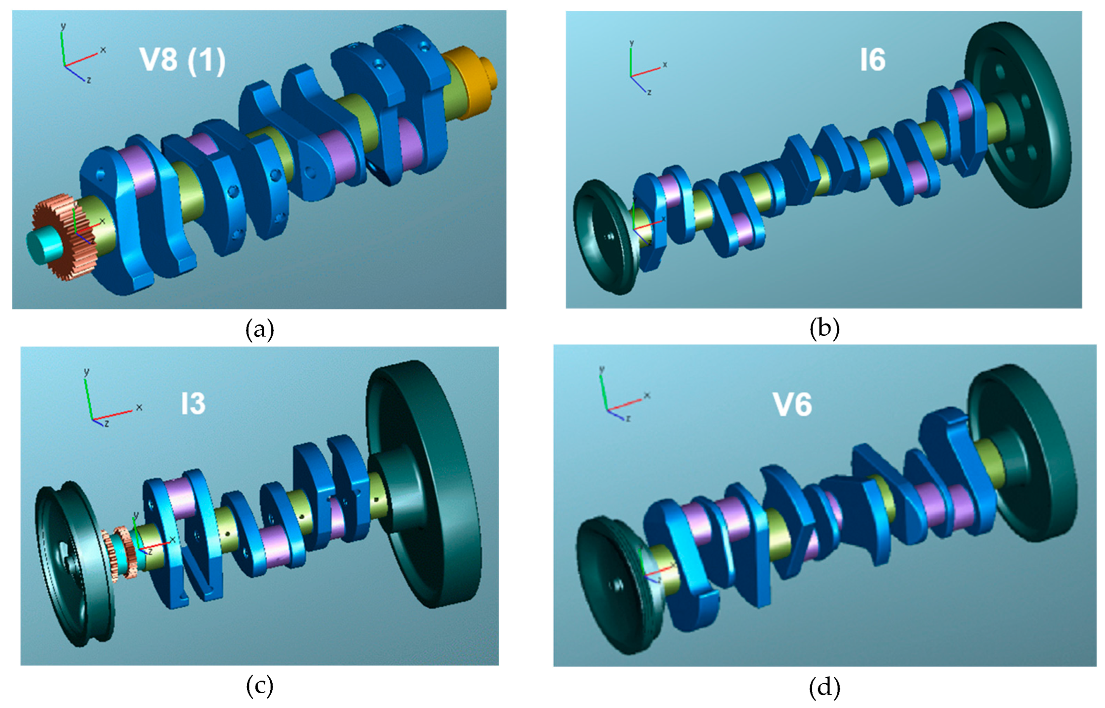
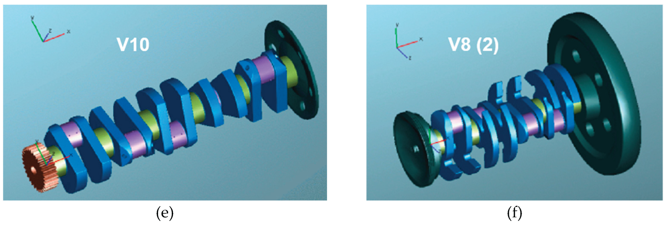
Figure 3.
Crankshaft structured FE models as assembled by AVL EXCITE™ Shaft Modeler [1].
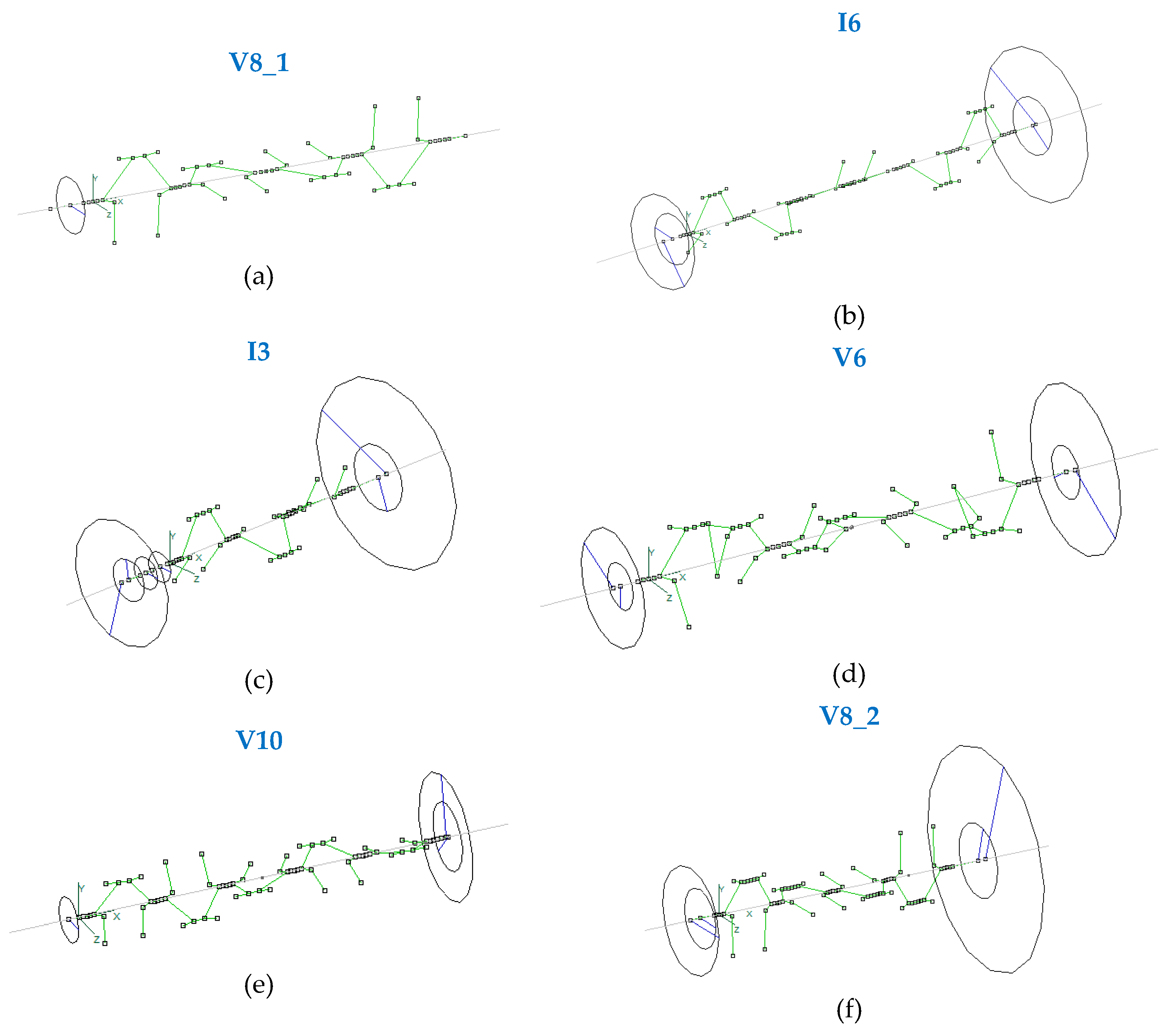
Figure 4.
Stiffness added to lateral translational DOFs of a main journal node.
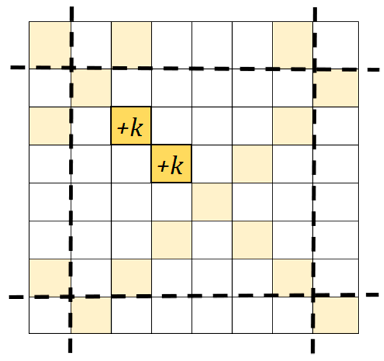
Figure 5.
Mass added to lateral translational DOFs of a crank pin node.
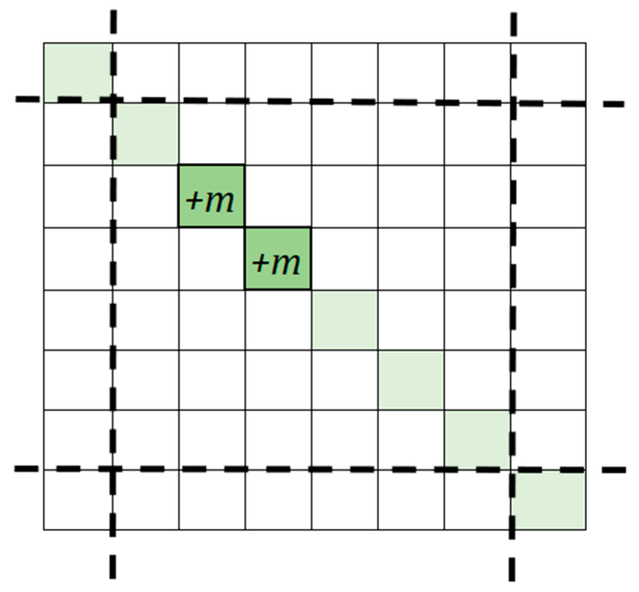
Figure 6.
Processed CAD model of 4-cylinder engine crankshaft [15].
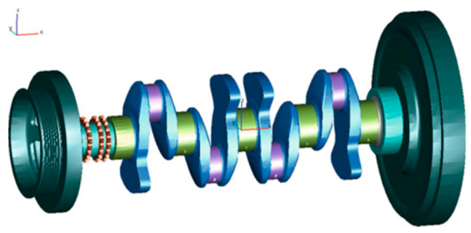
Figure 7.
Structured FE model of 4-cylinder engine crankshaft [15].
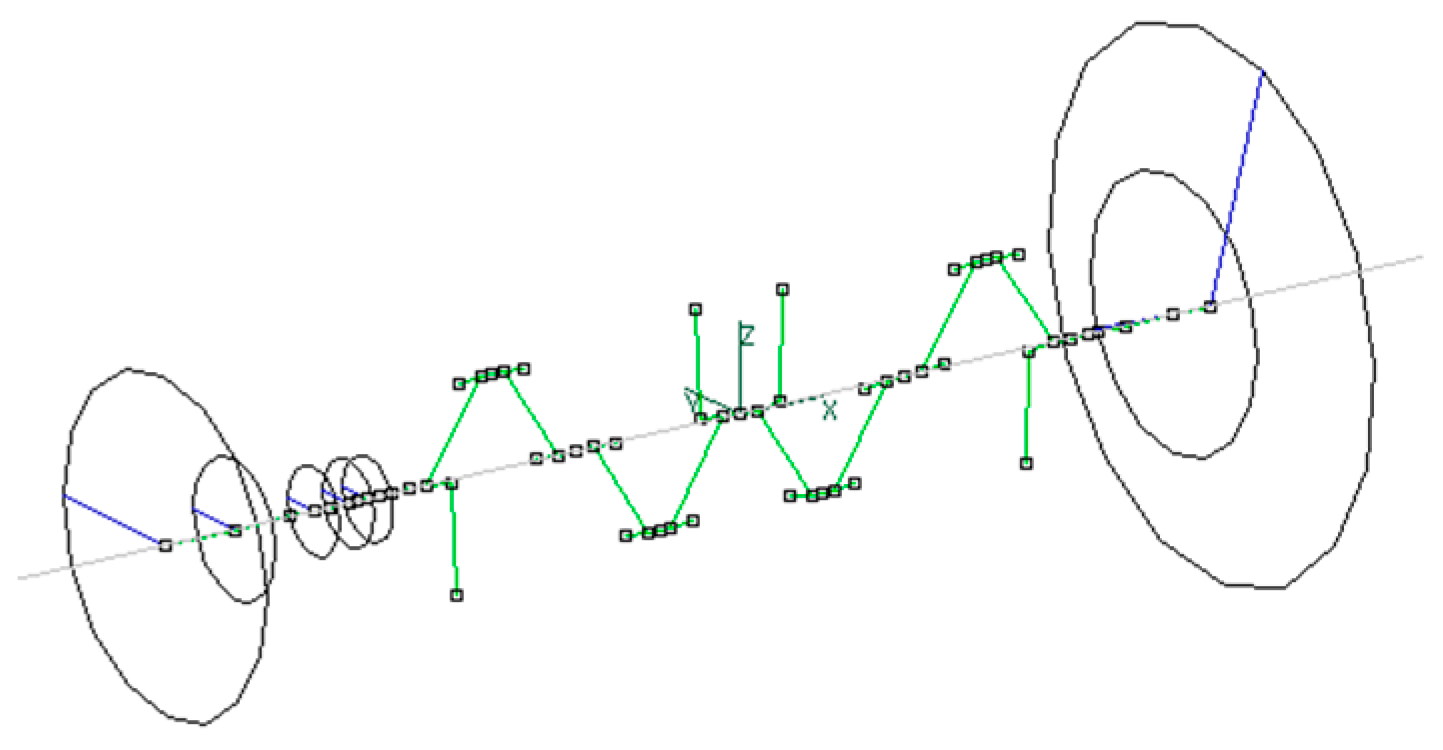
Figure 8.
First “half-wave, in-plane” bending mode shape of free 4-cylinder engine crankshaft at 123.8 Hz.
Figure 8.
First “half-wave, in-plane” bending mode shape of free 4-cylinder engine crankshaft at 123.8 Hz.
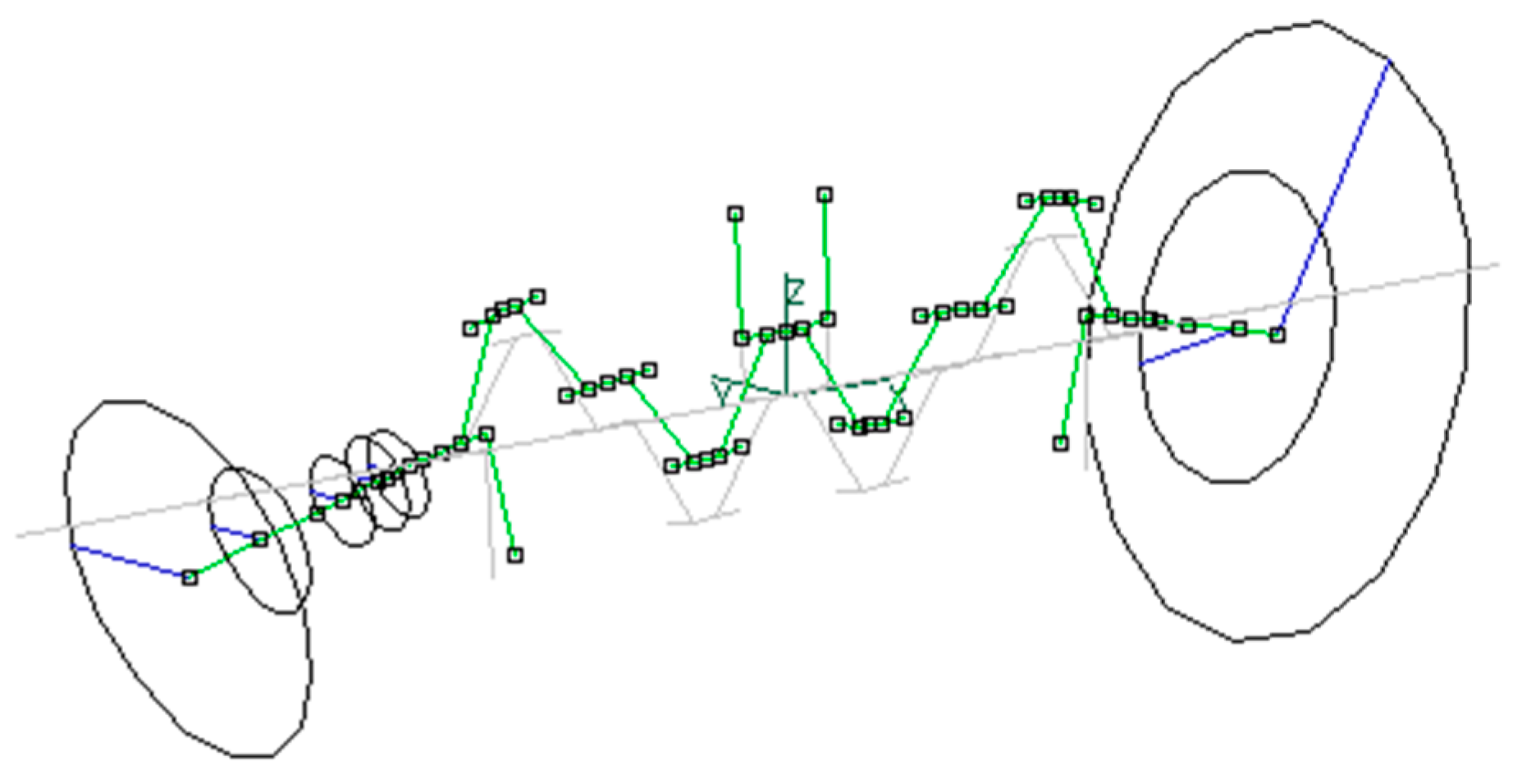
Figure 9.
Second bending mode shape (in XY plane) of free V8_1 crankshaft at 370.5 Hz.
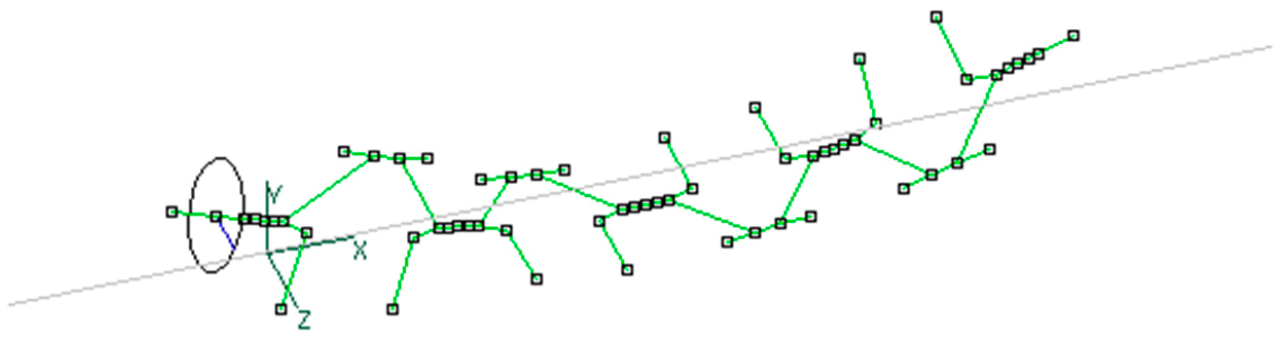
Figure 10.
Tension mode shape of free I6 crankshaft at 236.6 Hz.
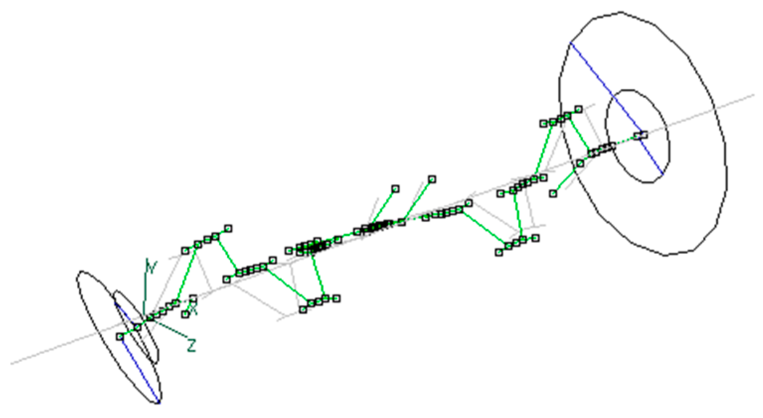
Figure 11.
Mixed mode shape of free I6 crankshaft at 479 Hz with nearly equal shares of motion in bending and in tension.
Figure 11.
Mixed mode shape of free I6 crankshaft at 479 Hz with nearly equal shares of motion in bending and in tension.
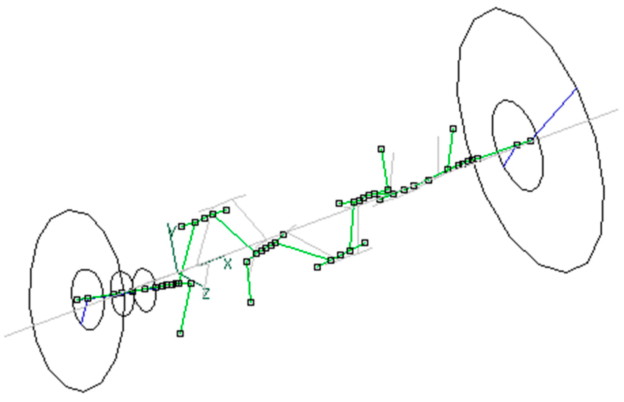
Figure 12.
Torsional mode shape of free V6 crankshaft at 438.2 Hz.
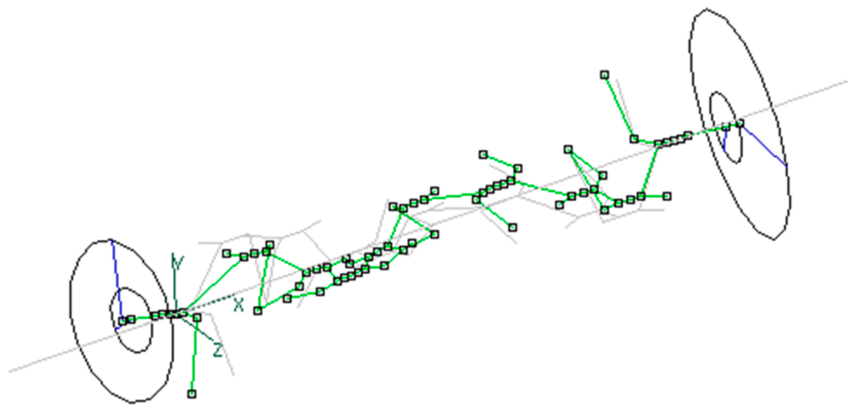
Figure 13.
Bending dominated mode shape of free V10 crankshaft, with a substantial torsional component at 650 Hz.
Figure 13.
Bending dominated mode shape of free V10 crankshaft, with a substantial torsional component at 650 Hz.
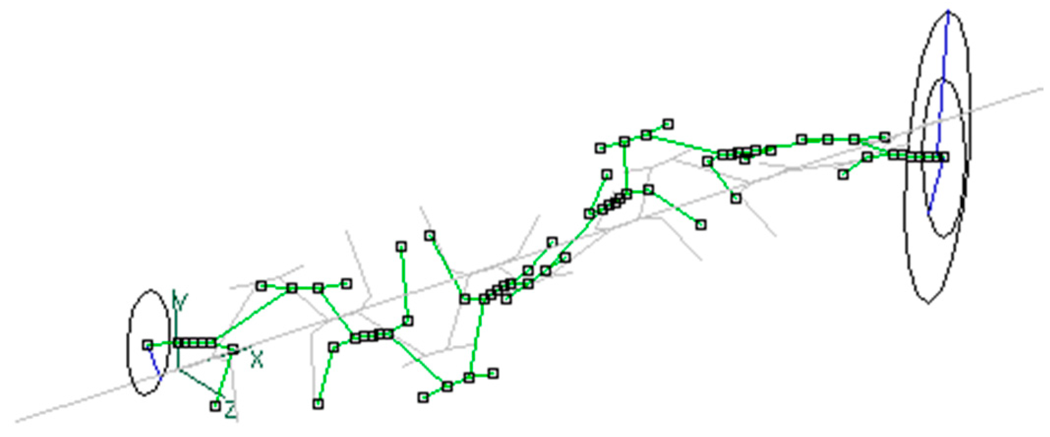
Figure 14.
Bending mode shape of free V8_2 crankshaft at 134 Hz.
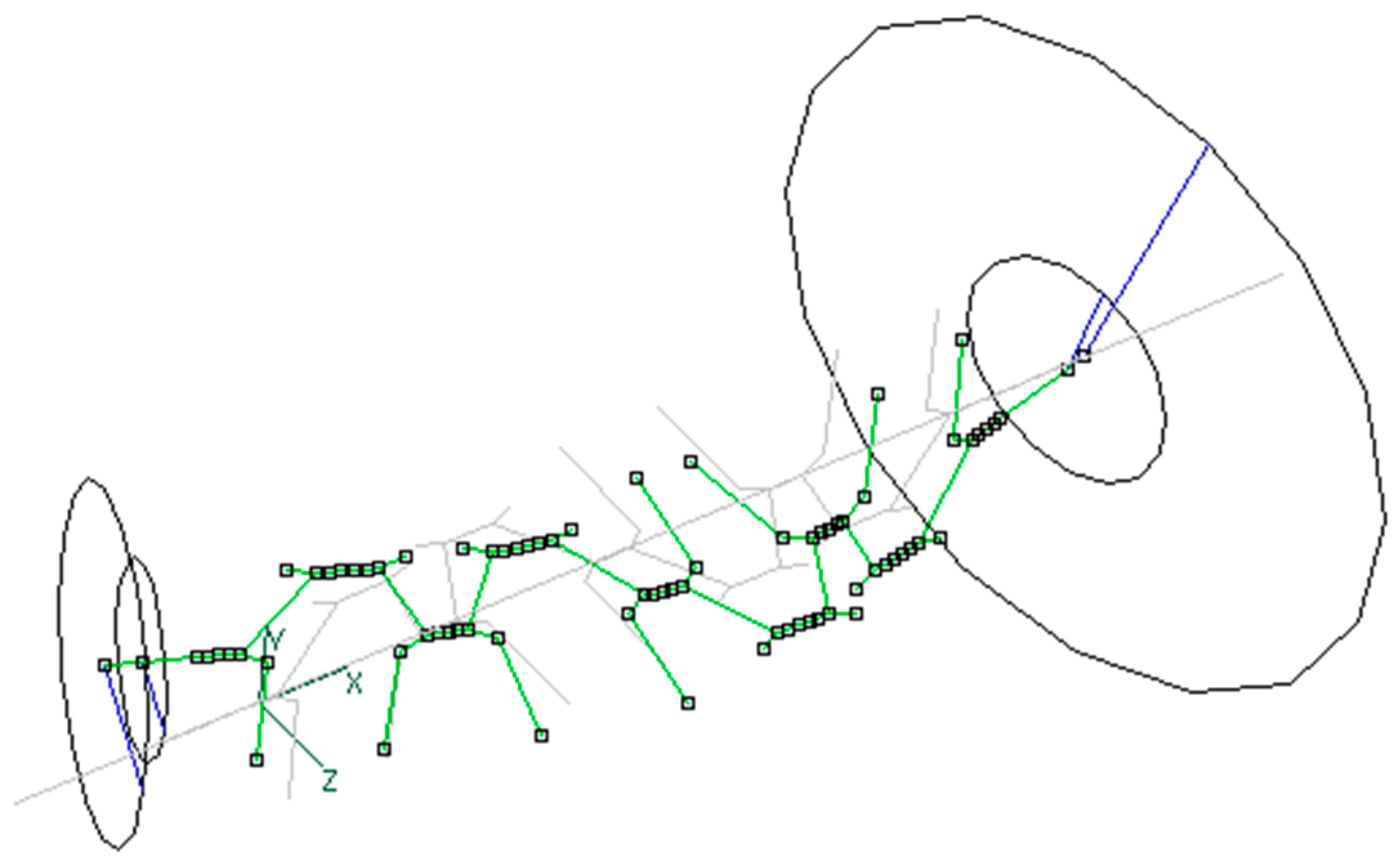

Table 1.
Some mass/inertia and stiffness parameters of seven engines considered in the paper.
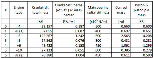
Table 2.
Frequency spectra of I4 crankshaft with different boundary conditions: a) free crankshaft, b) supported crankshaft, c) supported crankshaft with additional masses.
Table 2.
Frequency spectra of I4 crankshaft with different boundary conditions: a) free crankshaft, b) supported crankshaft, c) supported crankshaft with additional masses.
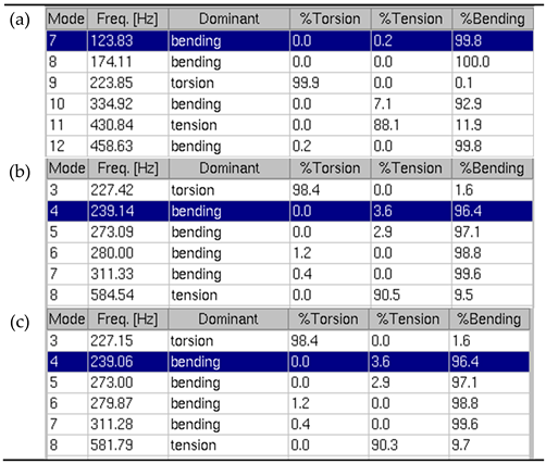
Table 3.
Frequency spectra of the V8_1 crankshaft with different boundary conditions: a) free crankshaft, b) supported crankshaft, 3) supported crankshaft with additional masses.
Table 3.
Frequency spectra of the V8_1 crankshaft with different boundary conditions: a) free crankshaft, b) supported crankshaft, 3) supported crankshaft with additional masses.
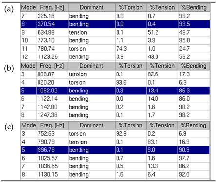
Table 4.
Frequency spectra of I6 crankshaft with different boundary conditions: a) free crankshaft, b) supported crankshaft, 3) supported crankshaft with additional masses.
Table 4.
Frequency spectra of I6 crankshaft with different boundary conditions: a) free crankshaft, b) supported crankshaft, 3) supported crankshaft with additional masses.
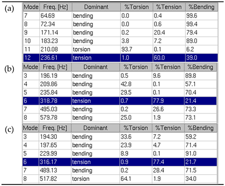
Table 5.
Frequency spectra of I3 crankshaft with different boundary conditions: a) free crankshaft, b) supported crankshaft, 3) supported crankshaft with additional masses.
Table 5.
Frequency spectra of I3 crankshaft with different boundary conditions: a) free crankshaft, b) supported crankshaft, 3) supported crankshaft with additional masses.
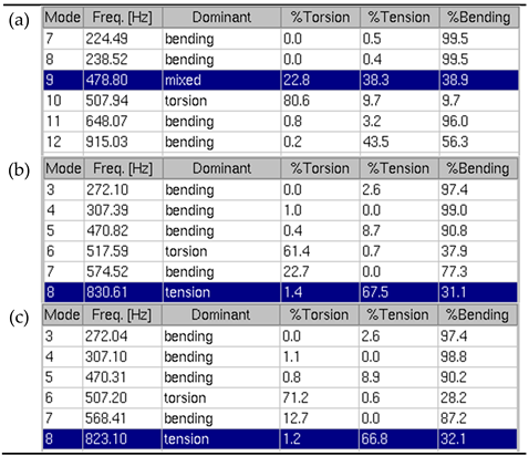
Table 6.
Frequency spectra of V6 crankshaft with different boundary conditions: a) free crankshaft, b) supported crankshaft, 3) supported crankshaft with additional masses.
Table 6.
Frequency spectra of V6 crankshaft with different boundary conditions: a) free crankshaft, b) supported crankshaft, 3) supported crankshaft with additional masses.
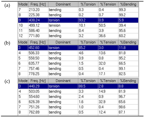
Table 7.
Frequency spectra of V10 crankshaft with different boundary conditions: a) free crankshaft, b) supported crankshaft, 3) supported crankshaft with additional masses.
Table 7.
Frequency spectra of V10 crankshaft with different boundary conditions: a) free crankshaft, b) supported crankshaft, 3) supported crankshaft with additional masses.
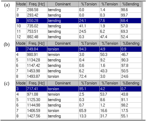
Table 8.
Frequency spectra of V8_2 crankshaft with different boundary conditions: a) free crankshaft, b) supported crankshaft, 3) supported crankshaft with additional masses.
Table 8.
Frequency spectra of V8_2 crankshaft with different boundary conditions: a) free crankshaft, b) supported crankshaft, 3) supported crankshaft with additional masses.
Disclaimer/Publisher’s Note: The statements, opinions and data contained in all publications are solely those of the individual author(s) and contributor(s) and not of MDPI and/or the editor(s). MDPI and/or the editor(s) disclaim responsibility for any injury to people or property resulting from any ideas, methods, instructions or products referred to in the content. |
© 2026 by the authors. Licensee MDPI, Basel, Switzerland. This article is an open access article distributed under the terms and conditions of the Creative Commons Attribution (CC BY) license (http://creativecommons.org/licenses/by/4.0/).
Copyright: This open access article is published under a Creative Commons CC BY 4.0 license, which permit the free download, distribution, and reuse, provided that the author and preprint are cited in any reuse.


