Preprint
Article

This version is not peer-reviewed.

Performance Analysis of a Solar-Air Source Absorption Heat Pump with Different Working Fluid

A peer-reviewed version of this preprint was published in:
Energies 2026, 19(6), 1508. https://doi.org/10.3390/en19061508

Submitted:

13 February 2026

Posted:

14 February 2026

You are already at the latest version

Abstract

A solar-air source absorption heat pump (SAAHP), which mainly consists of a solar collector, a fan coil, and an absorption heat pump equipped with a gas-fired combustor, has been proposed for water heating. This system runs in SD (Solar-energy driving) or GD (Gas-combustion-heat driving) mode, designed to utilize renewable energies as much as possible. The models for each component were built and the corresponding heat and mass balance equations were established. The performance of SAAHP based on LiBr/H2O and LiNO3/H2O working fluids was simulated and compared with an air source absorption heat pump (AAHP) based on LiBr/H2O. Results indicated that SAAHP based on LiNO3/H2O has a higher solar energy utilization rate than that based on LiBr/H2O due to its lower solar collector inlet temperature in SD mode. In comparison to AAHP based on LiBr/H2O, SAAHP based on both of LiBr/H2O and LiNO3/H2O achieved a higher primary energy COP throughout a year. Relative to a gas-fired hot water boiler, SAAHP based on LiNO3/H2O and LiBr/H2O achieved yearly primary energy saving rates of 46.2% and 40.0%, respectively, whereas AAHP just achieved 12.2%. SAAHP based on LiNO3/H2O shows significant energy saving potential in the building energy consumption.

Keywords: 
;  ;  ;  

1. Introduction

With the rapid urbanization in China, building energy consumption and its proportion to the entire energy consumption have become greater and greater. By the end of 2023, the total building energy consumption of china reached 1.91 billion tce, and the building energy consumption had accounted for about 36.3% of the national total energy consumption [1]. Domestic hot water accounted for 23.4% in the building energy consumption in north urban areas [2]. Boilers burning various fuels are commonly used for supplying hot water, while such conventional water heating systems are not desirable in view of energy efficiency and environmental impact.
Due to being driven with heat, absorption heat pump (AHP) can be applied to utilize renewable energy or waste heat as both of the low temperature heat source and the driving heat source for supplying domestic hot water. At present, solar and air energy have been widely used in the building energy conservation. However, almost all research which has been focused on solar source absorption system is just for cooling purpose [3,4,5]. Air source absorption heat pump (AAHP), in which air energy is used as the low temperature heat source and fuel combustion heat is used as the driving heat source, has been investigated for heating water by some researchers [6,7,8]. However, AAHP meets some shortcomings in its application. In cold season, the same as air source electrical heat pump (ASEHP) [9], the performance of AAHP drops or it even does not work when the ambient temperature is too low [10,11]. Moreover, for AAHP, solar energy cannot be utilized and this is also undesirable in view of renewable energy utilization.
In order to improve AAHP and promote the utilization of renewable energy, in this paper, a solar-air source absorption heat pump (SAAHP) has been proposed for water heating, and its performance based on LiBr/H2O and LiNO3/H2O working fluids was simulated and compared with that of AAHP and gas-fired boiler throughout a typical meteorological year in Beijing.

2. System Descriptions

SAAHP mainly consists of an absorption heat pump equipped with a gas-fired combustor, a solar collector, a fan coil, and a hot water storage tank. The schematic diagram of SAAHP, which is operated in SD (Solar-energy Driving) or GD (Gas-combustion-heat Driving) mode, is shown in Figure 1.

2.1. SD (Solar-Energy Driving) Mode

In SD mode, the three-way valves 1 and 2 are switched to the generator, and the solar energy is used as the driving heat source. The three-way valves 3 and 4 are switched to the fan coil, and the air energy is used as the low temperature heat source. The city water is heated successively in the absorber and the condenser, and stored in the hot water tank for use.

2.2. GD (Gas-Combustion-Heat Driving) Mode

In GD mode, the three-way valves 1 and 2 are switched to the evaporator, and the three-way valves 3 and 4 are switched to the solar collector. Here, the gas-fired combustor provides the driving heat source, and the solar energy is used as the low temperature heat source.
On precipitation days, if the hot water supply is short, the gas-fired combustor starts to operate in SD mode or GD mode for supplementing heat. In this case, pump 5 is to run.

2.3. Weather Data and the Building

The typical meteorological year weather data of Beijing (Meteorological Station: No.545110, latitude: 116o28′, longitude: 39 o 48′) can be found in China Meteorological Data Service Centre. The hourly data in a typical day in a month is defined as the average value of the hourly meteorological data in the corresponding month. The hourly solar radiation on the horizontal surface during a typical day is shown in Figure 2. The highest ambient temperature during a typical day and monthly precipitation days are given in Figure 3.
It is assumed that SAAHP is applied to supply domestic hot water for a student dormitory of 9-storey in the campus of University of Science and Technology, Beijing. The hot water is used for bathing from 2:00 PM to 11:00 PM. A roof area of 600 m2 is available for installing flat plate solar collectors. Based on the statistic gas consumption data from the boiler room and the gas boiler efficiency of 90%, the heat demand of hot water for this building was obtained. The monthly gas consumption and daily heat demand are shown in Figure 4.

3. Simulation of SAAHP

To simulate the performance of SAAHP using MATLAB software, the material property equations are given below, and the models for absorption heat pump, solar collector, fan coil and storage water tank have been built. In order to make the simulation convenient, some basic assumptions are given as follows:
(a) System is in a steady state; (b) Pressure drops and heat losses are ignored; (c) The throttling in expansion valve is isenthalpic; (d) The liquid solution leaves each unit in a saturated state.

3.1. Thermodynamic Property Equations

3.1.1. LiNO3/H2O Working Fluid

The vapor pressure of LiNO3/H2O working fluid was measured in a temperature range from 297.65 to 473.15 K and an absorbent mass fraction range from 50 to 70 %, respectively [12]. The experimental data of vapor pressure are fitted to Antoine Eq. 1 [13].
log P L i N O 3 = i = 0 4 [ A i + { B i / ( T C i ) } ] ( 100 w ) i
where Ai, Bi and Ci are the regression parameters and their values are listed in Table 1.
The specific enthalpies of LiNO3/H2O working fluid were measured in a temperature range from 303.15 to 373.15 K and an absorbent mass fraction range from 45 to 60 %, respectively [14]. The experimental data are fitted to polynomial Eq. 2 [15].
h L i N O 3 = i = 0 4 A i ( 100 w ) i + T i = 0 4 B i ( 100 w ) i + T 2 i = 0 4 C i ( 100 w ) i
where Ai, Bi and Ci are the regression parameters and their values are listed in Table 2.

3.1.2. LiBr/H2O Working Fluid

The vapor pressure of LiBr/H2O working fluid is obtained from Ref. [16].
log P L i B r = k 0 + k 1 / ( T D + 273.15 ) + k 2 / ( T D + 273.15 ) 2
where TD is the dew point which is fitted to the following equation:
T D = i = 0 2 j = 0 3 A i j ( w 40 ) j t i
The values of k0, k1, k2 and Aij are given in Table 3.
The specific enthalpy of LiBr/H2O working fluid reported in Ref. [17] is fitted to polynomial Eq. 5 by a least-squares method:
h L i B r = i = 0 4 A i ( 100 w ) i + T i = 0 4 B i ( 100 w ) i + T 2 i = 0 4 C i ( 100 w ) i
where Ai, Bi and Ci are the regression parameters and their values are listed in Table 4.

3.1.3. Saturated Water, Saturated Water Vapor, and Superheated Steam

The saturation pressures of water vapor used in this paper are from Handbook of Chemical and Engineering Property Data [18]. The regression equation is given below:
P w = i = 0 6 A i T i ( 273.15 T 373.15 K )
where Ai is the regression parameters and the value is listed in Table 5.
The specific enthalpies of saturated water and saturated vapor are obtained according to the fitting equations reported in literature [15]:
h v = 0.00125397 t 2 + 1.88060937 t + 2500.559
h l a t e n t = 0.00132635 t 2 2.29983657 t + 2500.43063
where hv is the enthalpy of saturated water vapor, and hlatent is the latent heat of condensation. The enthalpy of saturated water is obtained according to the Eq.9:
h w = h v h l a t e n t  
The specific enthalpy of superheated steam is obtained from Ref. [19]:
h s h = B 0 + B 1 T + B 2 T 2 + B 3 ( P / 1000 ) / T B 4 + B 5 ( P / 1000 ) 2 / T B 6
The values of the coefficients are listed in Table 6.

3.1.4. Specific Enthalpy of Air

According to the data reported in Handbook of Chemical and Engineering Property Data [18], the following equation for the specific enthalpy of air is obtained by a least square fitting:
h a = A 0 + A 1 T + A 2 T 2 + A 3 T 3 + A 4 / T ( 250 T 390 K )
The values of the regression parameters are given in Table 7.

3.2. Modeling of Absorption Heat Pump

The diagram of h-w and p-t are given in Figure 5, and the typical points in Figure 5 are in one-to-one correspondence with the points in Figure 1. According to the laws of mass and energy conservation, the following formulas are obtained. Here, the refrigerant flow rate D is assumed as 1 kg/s.
  • Flow ratio α
The flow ratio α is the ratio of the circulation flow rate of dilute solution to the flow rate of refrigerant.
α = w 2 w 2 w 1
where w1 and w2 are the concentrations of dilute solution and concentrated solution.
2.
Solution heat exchange:
The heat recovery efficiency and heat load of the solution heat exchanger are defined as the following equations [20]:
η S H X = t 4 t 8 t 4 t 2
Q S H X = D α ( h 7 h 2 ) = D ( α 1 ) ( h 4 h 8 )
3.
Heat load of the evaporator:
D h 3 + Q E = D h 1 '
q E = h 1 ' h 3
4.
Heat load of the generator:
Q G + α D h 7 = ( α 1 ) D h 4 + D h 3 '
q G = ( α 1 ) h 4 + h 3 ' α h 7 = h 3 ' h 4 + α ( h 4 h 7 )
5.
Heat load of the condenser:
D h 3 ' = Q C + D h 3
q C = h 3 ' h 3
6.
Heat load of the absorber:
D h 1 ' + D ( α 1 ) h 8 = Q A + D α h 2
q A = h 1 ' + ( α 1 ) h 8 α h 2
7.
Coefficient of performance (COP) and Primary energy COP:
C O P = Q C + Q A Q G
C O P p r i = Q C + Q A Q p r i
where Qpri is the primary energy consumption converted from system’s total energy consumption, including the consumed electric power and natural gas.

3.3. Solar Collector

The flat plate solar collector (P-G/0.6-T/L-1.83-4, Beijing Solar Energy Research institute Co., Ltd.) is adopted. The thermal performance of this solar collector has been tested by National Center for Quality Supervision and Testing of Solar Heating Systems (Beijing).The solar collector arrays are installed at a tilt 39.8 o toward the south (The azimuth angle γ is zero). The efficiency of flat plate solar collector is given by Duffie and Beckmann [21]:
η s = F R ( τ α ) F R U L ( t s , i n t a m ) / I T
where IT is the incident solar radiation on a tilted surface, and it can be calculated by the following equation :
I T = I b R b + I d ( 1 + cos β 2 ) + ( I b + I d ) μ ( 1 cos β 2 )
where Ib and Id is the beam and diffuse radiation on the horizontal surface, β is the slope of the collector, μ is the surface albedo, and Rb is the geometric factor, the ratio of beam radiation on the tilted surface to that on a horizontal surface.
When the surface azimuth angle is 0 o, the ratio Rb can be calculated by:
R b = cos θ cos θ z = cos ( φ β ) cos δ cos ω + sin ( φ β ) sin δ cos φ cos δ cos ω + sin φ sin δ
where θ is the angle of incidence, θz is the zenith angle, φ is the latitude, ω is the hour angle, and δ is the declination. The declination δ can be calculated from the following equation:
δ = 23.45 sin ( 360 ° × 284 + n 365 )
where n is the day of the year and the recommended average days for months and values of n by months have been listed in Ref. [21].
The useful heat gain from the solar collector arrays is calculated by:
Q s = η s A s I T
The temperature of thermal medium (water used in this work) at the outlet of solar collector is expressed as:
t s , o u t = t s , i n + η s I T G C p
where Cp is the specific heat capacity of the medium and G is the mass flow rate in unit area of solar collector.

3.4. Fan Coil and Solution Pump

Air energy is used as the low temperature heat source through the fan coil in SD mode. The heat load of fan coil is determined with Eqs. 31 and 32.
Q a = Q s q G q E
Q a = ρ a v a ( h a , i n h a , o u t )
Combining Eqs. 31 with 32, the air volume flow rate νa can be calculated by:
v a = q E Q s ρ a ( h a , i n h a , o u t ) q G
Where, the density of air ρa is considered as a constant at ambient temperature.
The power consumption of the fan is expressed as the following equation [22]:
P F = v a Δ p a η F = q E Q s q G ρ a ( h a , i n h a , o u t ) ( Δ p coil + Δ p out ) η F
where pa is the evaporator resistance, ηF is the fan efficiency, pcoil is the resistance of coil, and pout is the excess pressure of fan outlet. As pa is proportional to the square of air velocity, PF is proportional to the cube of air volume flow rate, and it can be expressed as:
P F 1 = v a 1 3 v a 2 3 P F 2
The power consumption of solution pump is calculated by the following equation [23]:
P p = v p Δ p p η p = v p ( p out p in ) η p
where νp is the volume flow rate, pp is the pressure head of the solution pump, pout and pin are the outlet and inlet pressure of pump, and ηp is the pump efficiency.

3.5. Hot Water Storage Tank

An energy balance on the hot water storage tank during its storage period in sunshine time is expressed as:
d Q s t d t = q i n q o u t q s t l
where qin is the heat flowing into the storage tank, qout is the heat flowing out of the storage tank, and qstl is the heat losing to the ambient. Because the hot water consumption in university campus is always concentrated in the evening after 8:00 PM, to simplify the model, the small amounts of hot water consumed before peak time and the corresponding qout are ignored.
The heat qin supplied by SAAHP can be calculated:
q i n = m w h i n
where mw and hin are the mass flow rate and specific enthalpy of the hot water flowing into the storage tank, respectively. The mw is determined by the following equation:
m w = Q A c p , w Δ t A = Q C c p , w Δ t C
The heat loss of storage tank is expressed as:
q s t l = U s t A s t ( t s t t a m )
By combining the Eqs. 37, 38 and 40, the energy balance equation of the hot water storage tank in a short time step of ∆τ can be derived:
m w h i n Δ τ + m 0 h 0 U s t A s t ( t s t t a m ) Δ τ = ( m w + m 0 ) h 1
where h0 and m0 are the specific enthalpy and mass of the storage hot water at the present time, and h1 is the specific enthalpy of the storage hot water in the short time step of ∆τ.
As specific enthalpy is a function of temperature, after the specific enthalpy of the storage hot water is determined, the corresponding temperature can also be determined.
The volume of storage tank is calculated by:
V tan k = 0 t ' ( m w / ρ w ) d t
where ρw (kg m-3) is the density of the storage hot water and t' (s) is the storage time.

3.6. Primary Energy Coefficient of Performance (COP)

In this study, daily, monthly and yearly primary energy COP (COPpri,d, COPpri,m , and COPpri,y) have been defined as:
C O P p r i , d = Q i , d Q p r i , d = Q i , d W p , d + W F , d η g + Q G , d η c o m
C O P p r i , m = Q i , m ( n m n r ) × Q i , d C O P p r i , d + n r × Q G , d η c o m
C O P p r i , y = i = 1 i = 12 Q i , m i = 1 i = 12 Q i , m C O P p r i , m
where Qi,d and Qi,m are the daily and monthly heat demand of building, respectively, nm is the days of a month , and nr is the precipitation days. Considering that the share of thermal power in the national total power capacity is over 70 %, ηg at user end is set to be 35% [24].

3.7. Validation of the AHP Model

The absorption heat pump is the key part in SAAHP, so the validation of the AHP model is important. In order to make sure that the model and the MATLAB program is of sufficient accuracy, an absorption chiller with 3489 kW refrigeration capacity was calculated using the model expressed in this work, and compared with the results reported in Refs. [22,25]. As shown in Table 8, the comparisons indicate that the model can provide adequate accuracy with small deviation. For the reason that AHP has the same cycle and principle as the absorption chiller, the model and the program can also be used to simulate the performance of AHP.

4. Results and Discussion

Based on the above models, the performance of SAAHP with LiBr/H2O and LiNO3/H2O was simulated under the given operating conditions shown in Table 9. Considering the influence of the flow ratio to the power consumption of solution pump and the COP of absorption heat pump, the performance of SAAHP with LiBr/H2O and LiNO3/H2O was compared under the same flow ratio.
The main parameters, heat load and COP of AHP with LiBr/H2O and LiNO3/H2O at the refrigeration flow rate D=1 kg/s are listed in Table 10. The required generator temperature of AHP using LiNO3/H2O was lower than that using LiBr/H2O working fluid, and the former reached higher COP throughout a year. This is mainly because of the differences in the absorption property between the two working fluids.
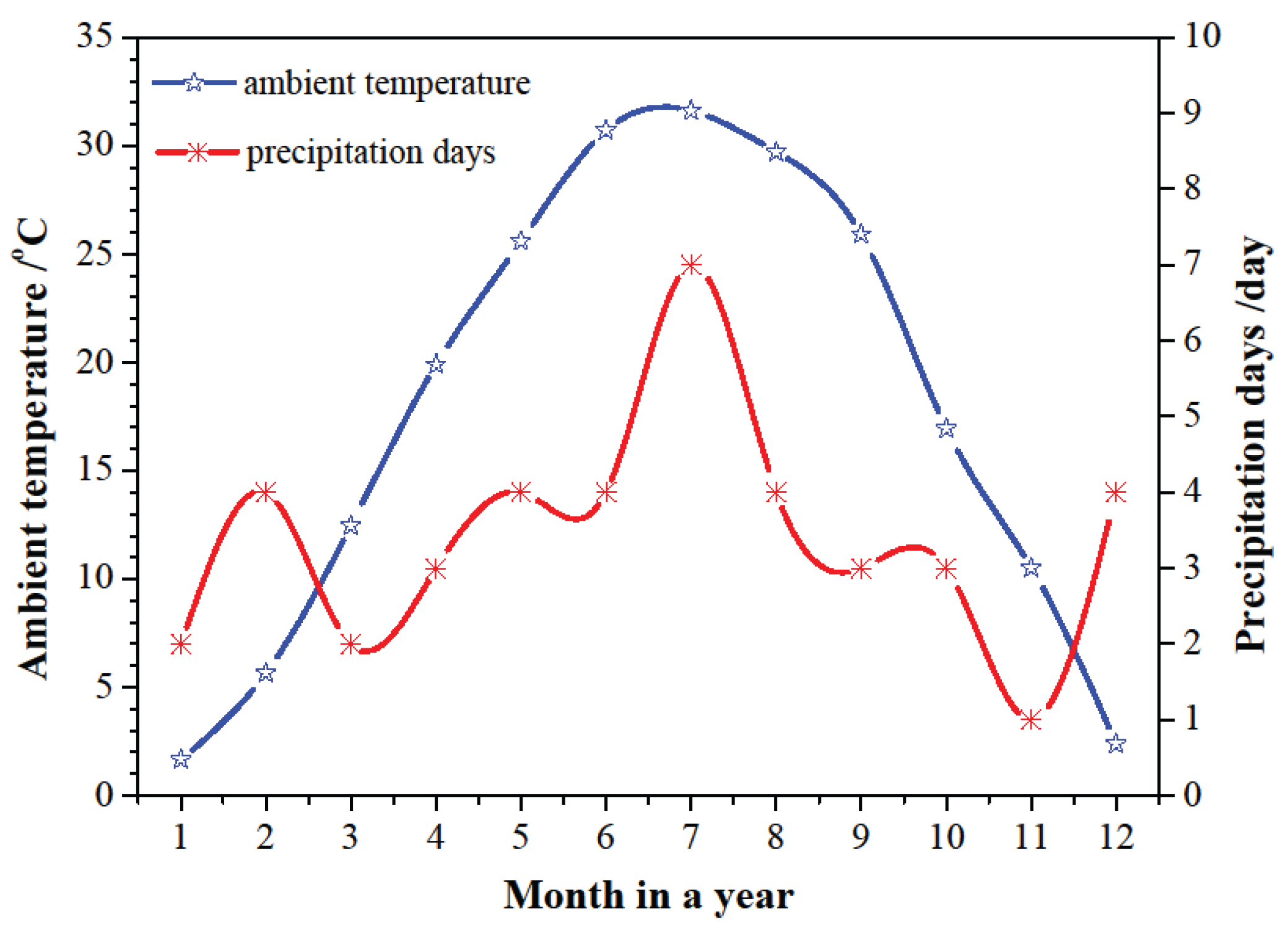
The switching time of the operating mode is determined with the ambient temperature and the heating capacity of SAAHP system. When SAAHP system runs in SD mode, the required ambient temperature in cold, moderate and hot seasons should be above 21.2 oC, 24.2 oC and 26.2 
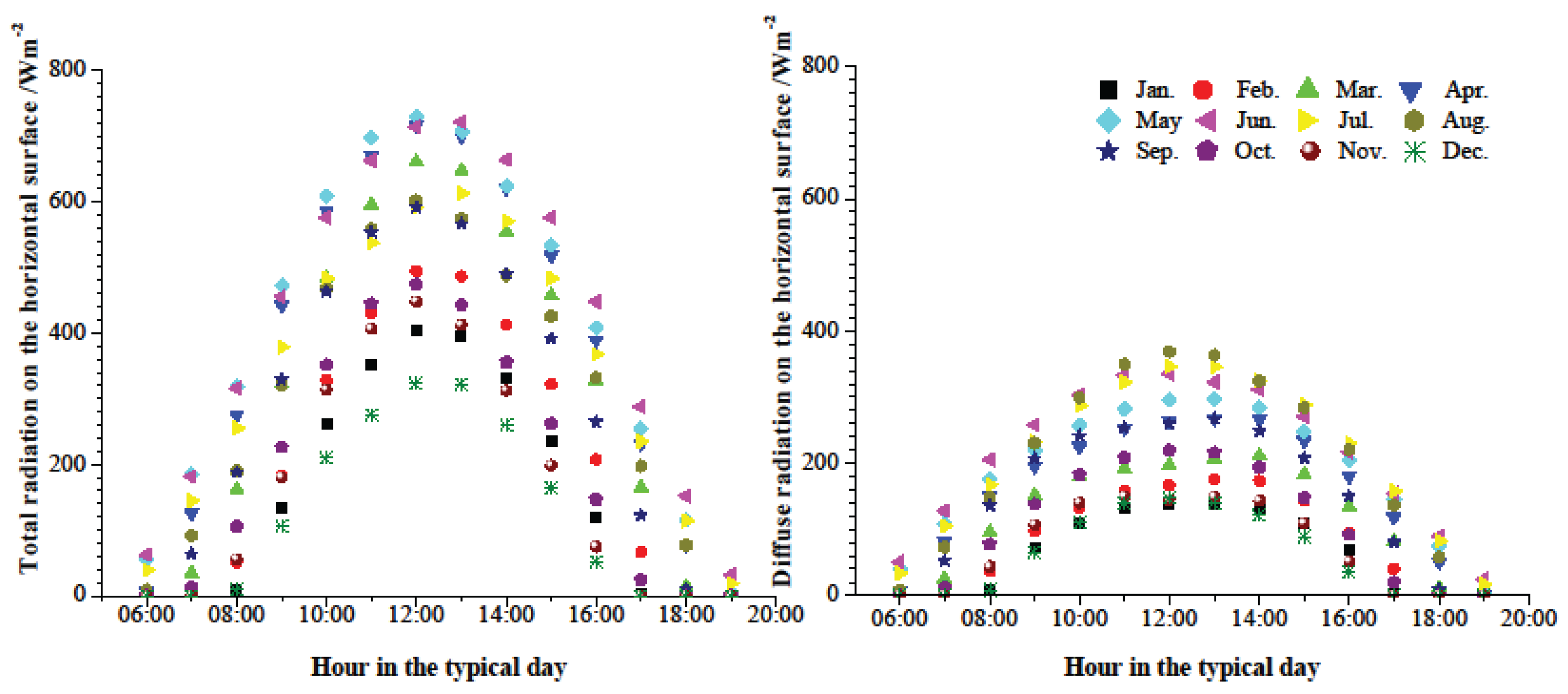
oC, respectively, under the given operating conditions. Based on the highest ambient temperature in a typical day shown in 
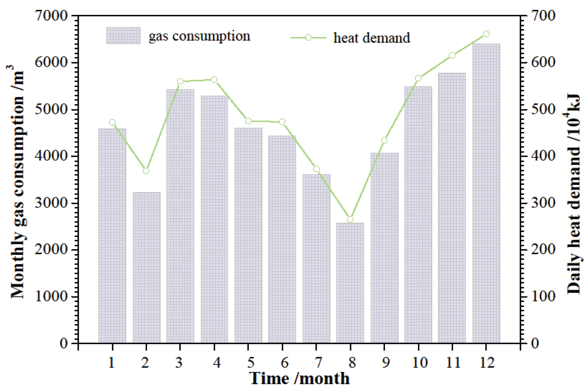
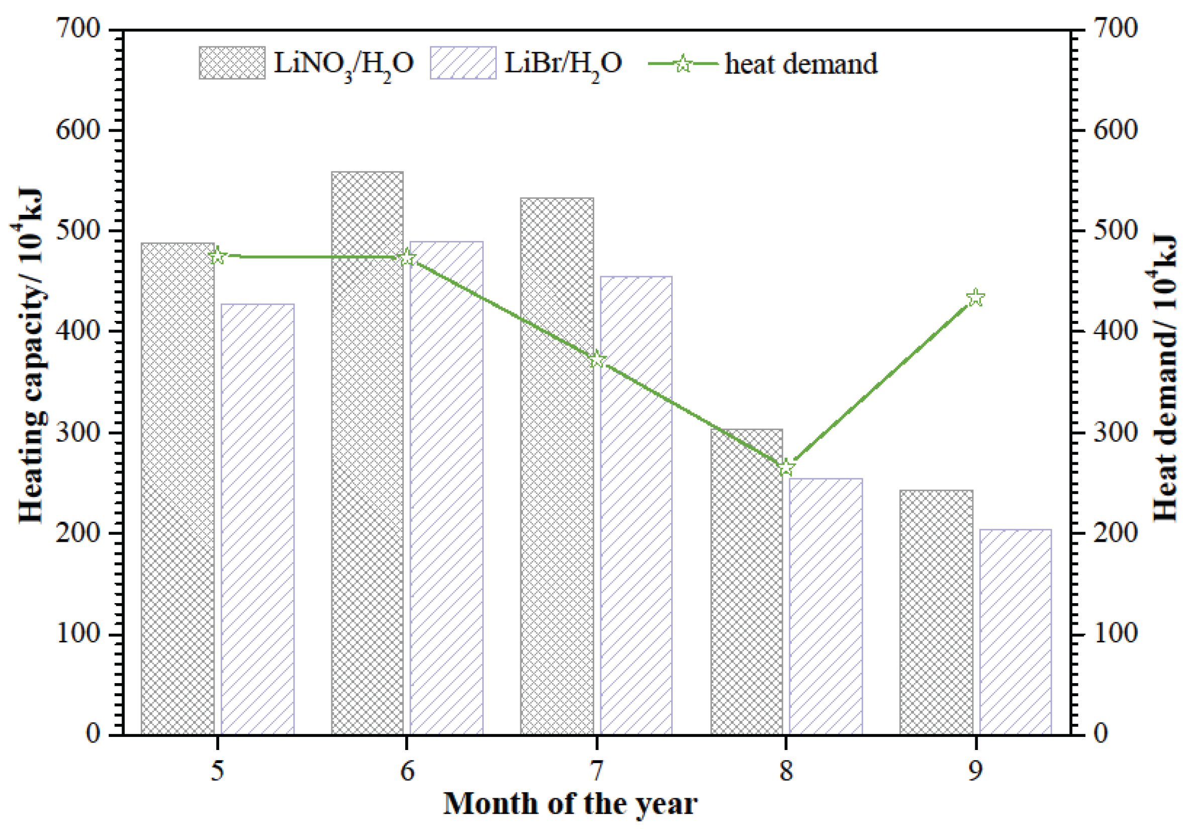
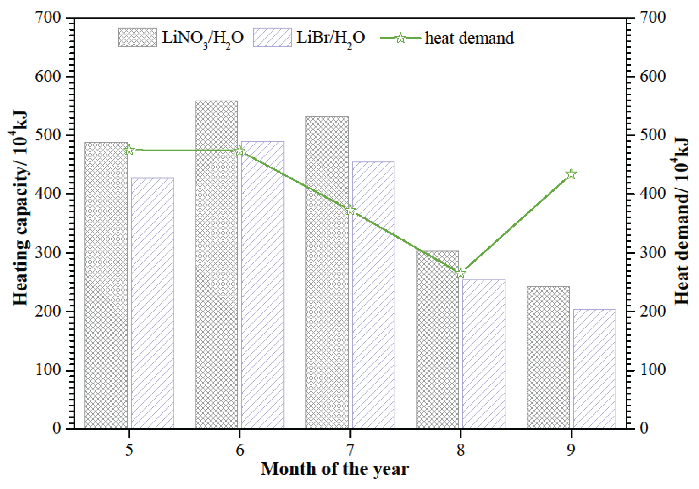
Figure 3, it is clear that the requirements can be meted in May to September. Beyond that, the heating capacity of SAAHP driven by solar energy in the above five months should meet the heat demand of the building. The heating capacity of SAAHP from May to September is presented in Figure 6. The heating capacity of SAAHP with LiNO3/H2O can meet the heat demand from May to August, so SAAHP with LiNO3/H2O shall be operated in SD mode during this period. However, the heating capacity of SAAHP with LiBr/H2O just meets the heat demand in June and July, so SAAHP with LiBr/H2O shall be operated in SD mode in the two months. It is indicated that LiNO3/H2O is more suitable for SD mode for the reason that SAAHP running in SD mode based on LiNO3/H
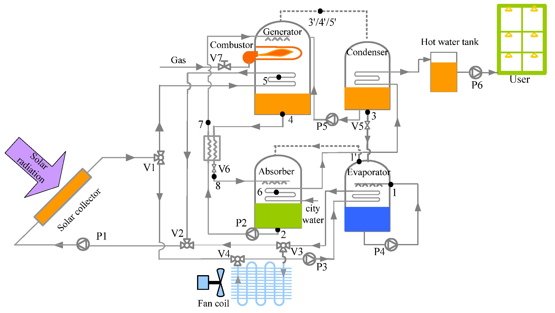
2O is able to utilize more solar energy. As seen in 
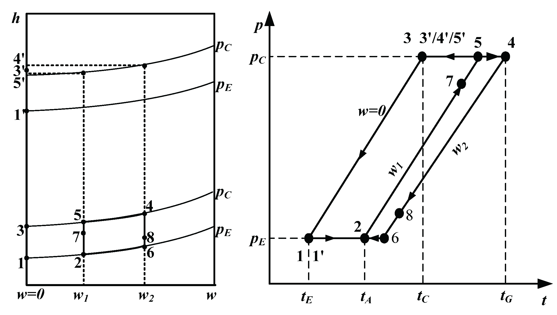
Figure 7, when the solar energy is used as the driving heat source in SD mode, the outlet temperature of the solar collector based on LiNO3/H2O is below 88 oC, which is about 4 oC lower than that based on LiBr/H2O. The reduction of the outlet temperature can improve the collector efficiency.
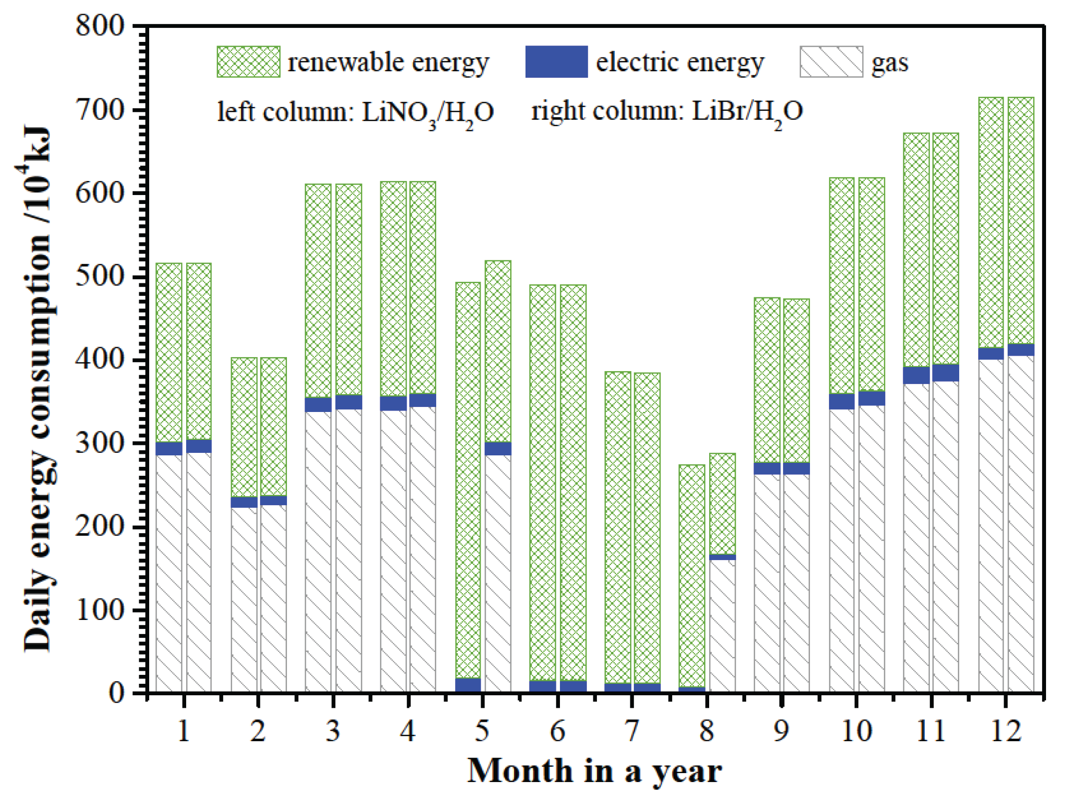
Figure 8 shows the daily energy consumption of SAAHP based on LiBr/H2O and LiNO3/H2O working fluids. Results indicated that the daily energy consumption of SAAHP running in GD mode based on different working fluids has no significant difference. However, SAAHP based on LiNO3/H2O is able to utilize more renewable energy than that based on LiBr/H2O since the former can be operated in SD mode for a longer period. Compared with the renewable energy and nature gas, the electric energy consumption by solution pump and fan is very small throughout a year.
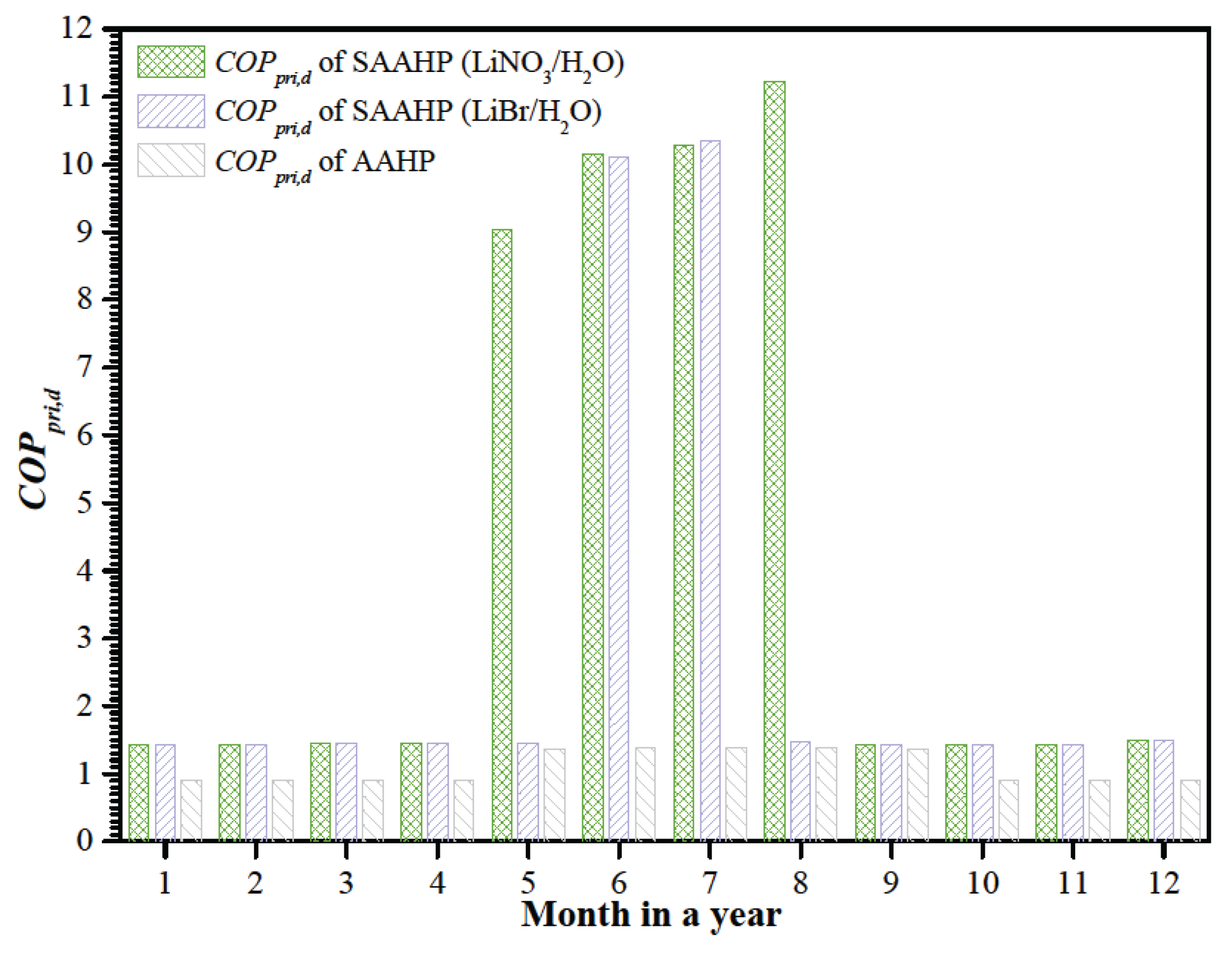
The daily primary energy COP (COPpri,d) of SAAHP based on LiBr/H2O and LiNO3/H2O are presented in Figure 9, and compared with that of a LiBr/H2O AAHP with 300 kW heating capacity under the same operating conditions. Results indicated SAAHP running in SD mode achieves the highest COPpri,d of 1.12 due to simultaneously utilizing solar and air energy, but AAHP just achieves the highest COPpri,d of 1.40 since it misses the utilization of high grade solar energy in hot season. COPpri,d of AAHP decreases with the decreasing ambient temperature. When the ambient temperature is too low to be utilized as the low temperature heat source, COPpri,d of AAHP drops to the efficiency ( 90%) of the gas-fired combustor installed in AAHP. In contrast, SAAHP can utilize solar energy instead of air energy at a low ambient temperature, and still achieve a higher COPpri,d above 1.43 in cold regions.
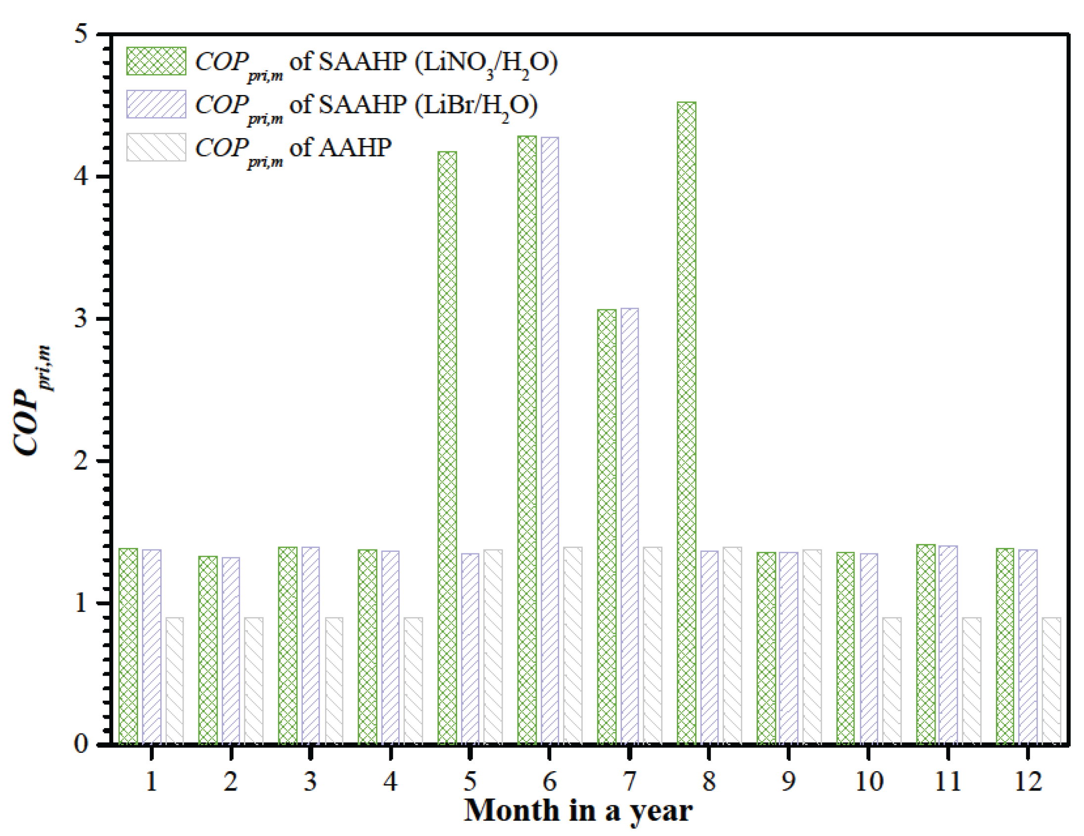
Figure 10 shows the monthly primary energy COP (COPpri,m) of SAAHP and AAHP. Considering the monthly precipitation days, COPpri,m of SAAHP running in GD mode has no obvious change, but that in SD mode is reduced relative to COPpri,d, especially in the rainy season of July. Though the precipitation day has a great influence on the primary energy consumption in SD mode, COPpri,m of SAAHP based on LiNO3/H2O working fluids is still above 3.07. By comparing COPpri,m of SAAHP with AAHP, it is seen that the former has a significant advantage throughout a year.
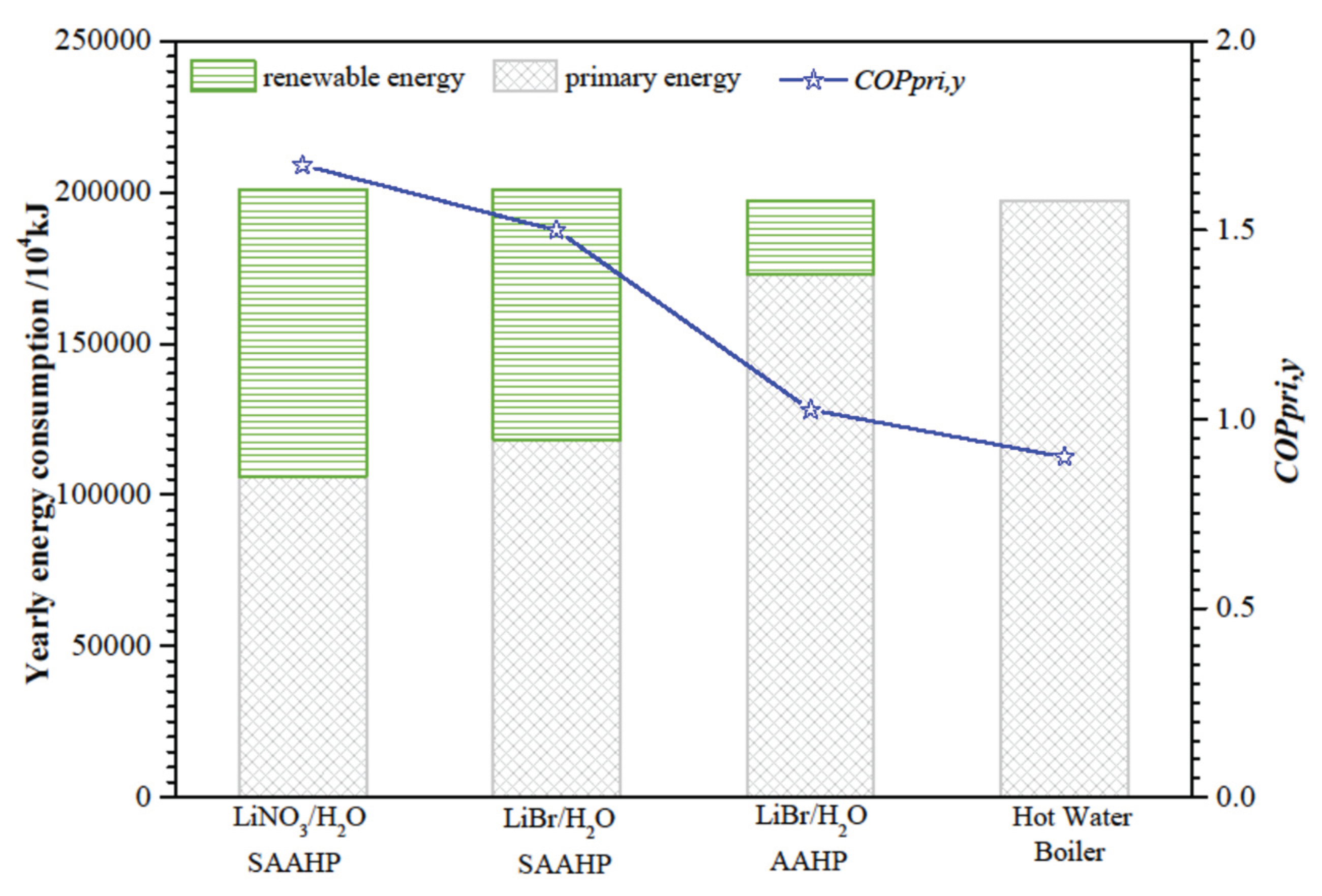
The yearly energy consumption and yearly primary energy COP (COPpri,y) of SAAHP and AAHP are shown in Figure 11. COPpri,y of SAAHP based on LiNO3/H2O and LiBr/H2O are 1.67 and 1.50, respectively, which are obviously larger than that of AAHP. Relative to a common gas-fired hot water boiler, SAAHP based on LiNO3/H2O and LiBr/H2O save 25631 Nm3 and 22213 Nm3 nature gas per year, whereas AAHP just saves 6766 Nm3 nature gas per year. It is clear that SAAHP has obvious advantage in primary energy saving over the gas-fired hot water boiler and AAHP.
In order to further investigate the primary energy-saving effect of SAAHP and AAHP, the yearly primary energy saving rate (YPESR) is defined as:
Y P E S R = E b o i l e r , y E p r i , y E b o i l e r , y
where Eboiler is the yearly primary energy consumption of the gas-fired hot water boiler, Epri,y is the yearly primary energy consumption of SAAHP or AAHP. Relative to the gas-fired boiler, SAAHP based on LiNO3/H2O and LiBr/H2O achieve yearly primary energy saving rates of 46.2% and 40.0%, respectively, while AAHP just achieves a yearly primary energy saving rate of 12.2%. Obviously compared to AAHP, SAAHP shows a great advantage in building energy saving, and its primary energy-saving effect can be further improved by using LiNO3/H2O instead of LiBr/H2O.
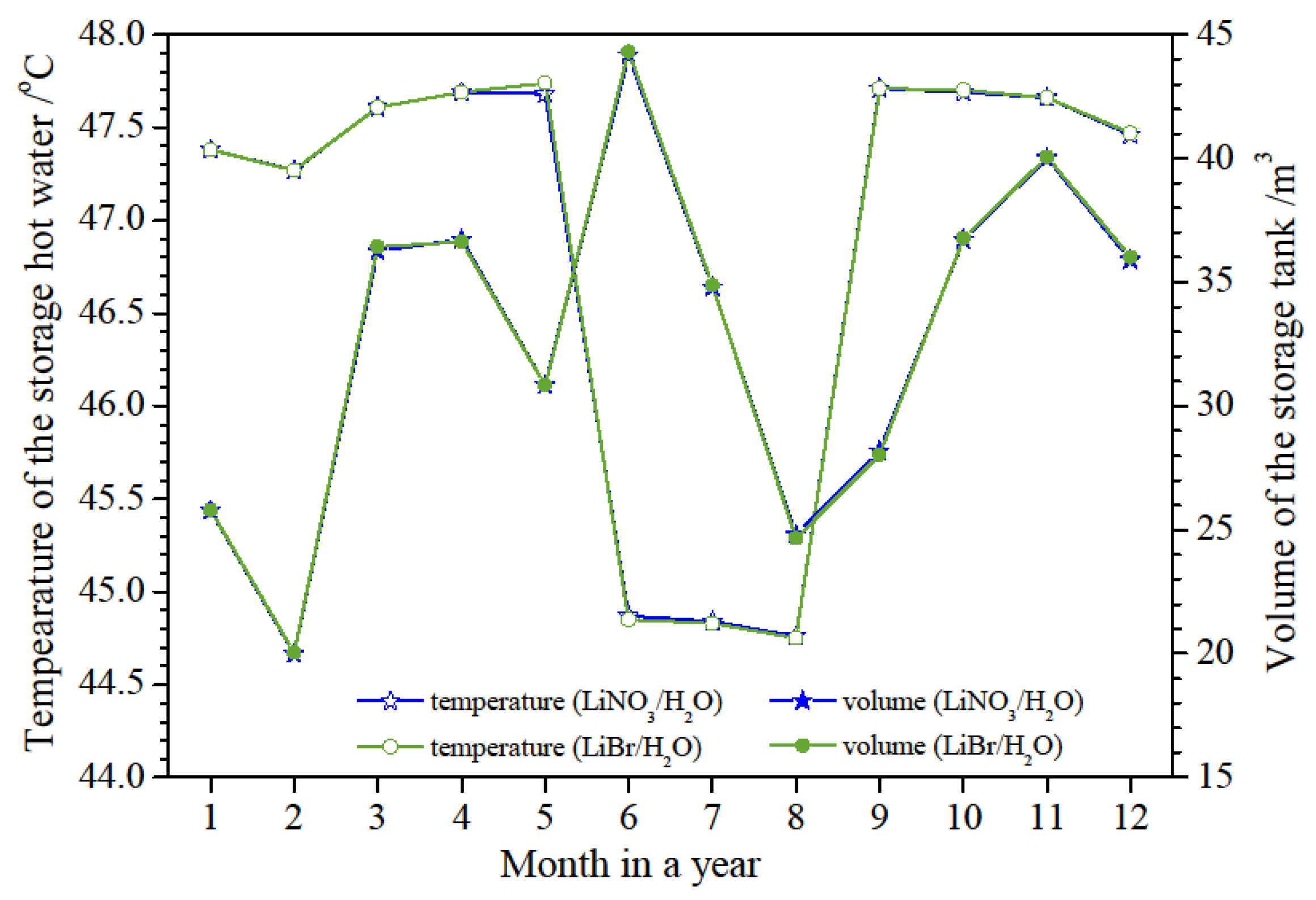
The temperature and volume of the storage hot water before bathing peak time in different months are shown in Figure 12. It can be seen that the hot water temperatures and the storage volumes based on LiBr/H2O and LiNO3/H2O working fluids have no significant differences throughout a year. The temperature of the storage hot water is above 44.8 oC in hot season and 47.3 oC in other seasons, respectively. The storage volume in the tank varies from 20 m3 to 44 m3 throughout a year due to the influences of the building heat demand and the temperature of city water. The storage tank used in this system should be more than 44 m3 to meet the storage requirement through the all months.

5. Conclusions

A novel SAAHP combining a solar collector and a fan coil with absorption heat pump equipped with a gas-fired combustor, in which renewable energies of solar energy and air energy can be utilized simultaneously, has been presented. The models for each component were set up and the corresponding heat and mass balance equations were established. The performances of SAAHP based on LiBr/H2O and LiNO3/H2O were simulated throughout a year and compared with that of AAHP based on LiBr/H2O and gas-fired hot water boiler. The main conclusions are as follows:
(1) Compared with SAAHP based on LiBr/H2O, SAAHP based on LiNO3/H2O has a significant advantage because of requiring a 4 oC lower solar collector inlet temperature in SD mode.
(2) SAAHP running in SD mode achieved the highest COPpri,d of 1.12 by simultaneously utilizing solar and air energy, while AAHP just achieved the highest COPpri,d of 1.40 due to missing the high grade solar energy in hot season. SAAHP running in GD mode achieved a higher COPpri,d above 1.43 by utilizing solar energy instead of air energy compared to AAHP, whose COPpri,d decreased dramatically due to the low ambient temperature in cold season. Taking the precipitation days into consideration, SAAHP still achieved a higher monthly primary energy COP throughout a year.
(3) Relative to the gas-fired hot water boiler, SAAHP based on LiNO3/H2O and LiBr/H2O achieved yearly primary energy saving rates of 46.2% and 40.0%, respectively, whereas AAHP just achieved 12.2%. SAAHP based on LiNO3/H2O has significant energy saving potential in the building energy consumption.

Funding

“This research was funded by the Foundation for talented young people of Anhui Polytechnic University, China (NO.: S022020033). ”

Conflicts of Interest

“The authors declare no conflicts of interest.”

Abbreviations

The following abbreviations are used in this manuscript:
A area, m2
COP coefficient of performance
Cp specific heat capacity, kJ kg-1 oC-1
D vapor flow, kg s-1
FR heat transfer factor
G mass flow rate in the unit area of collector, kg s-1 m-2
h specific enthalpy, kJ kg-1
I solar radiation, W m-2
m mass flow rate, kg s-1
P power, W
q specific heat load, kJ s-1 kg-1
Q heat load, kJ s-1
t temperature, oC
T absolute temperature, K
U heat loss coefficient, W m-2 oC-1
v volume flow rate , m3 s-1
w mass concentration, %
W power consumptions, kJ
∆p pressure drop, Pa
∆t temperature difference
∆τ time step, second
α flow ratio, no unit
β slope angle, o
γ azimuth angle, o
δ declination, o
η efficiency, %
θ incidence angle, o
μ surface albedo, no unit
ρ density, kg m-3
τα collector transmissivity and absorptivity product, no unit
φ latitude, o
ω hour angle, o

References

  1. CABEE. Research Report on Building Energy Consumption and Carbon Emissions in China (2023). Architecture 2024, 02, 46–59. [Google Scholar]
  2. Wu, W.; Shi, W.; Wang, B.; et al. A new heating system based on coupled air source absorption heat pump for cold regions: Energy saving analysis. Energy conversion and management 2013, 76, 811–817. [Google Scholar] [CrossRef]
  3. IBRAHIM, Nasiru I.; et al. Solar cooling with absorption chillers, thermal energy storage, and control strategies: A review. Journal of Energy Storage 2024, 97, 112762. [Google Scholar] [CrossRef]
  4. Song, M.; et al. Performance analysis of a solar single-effect absorption/compression hybrid refrigeration system with integrated absorption energy storage. Energy Conversion and Management 2024, 312, 118524. [Google Scholar] [CrossRef]
  5. Altiokka, A.; Arslan, O. Design and optimization of absorption cooling system operating under low solar radiation for residential use. Journal of Building Engineering 2023, 73, 106697. [Google Scholar] [CrossRef]
  6. Long, J.; et al. Study on energy-saving operation of a combined heating system of solar hot water and air source heat pump. Energy Conversion and Management 2021, 229, 113624. [Google Scholar] [CrossRef]
  7. Wang, C.; et al. Experimental investigation and performance evaluation on a direct expansion solar-air source heat pump system. International Journal of Refrigeration 2023, 145, 168–176. [Google Scholar] [CrossRef]
  8. Wu, W.; Wang, B.; Shi, W.; et al. Techno-economic analysis of air source absorption heat pump: Improving economy from a design perspective. Energy and buildings 2014, 81, 200–210. [Google Scholar] [CrossRef]
  9. Shao, S.; Shi, W.; Li, X.; et al. A new inverter heat pump operated all year round with domestic hot water. Energy conversion and management 2004, 45(13-14), 2255–2268. [Google Scholar] [CrossRef]
  10. Wu, W.; Zhang, X.; Li, X.; et al. Comparisons of different working pairs and cycles on the performance of absorption heat pump for heating and domestic hot water in cold regions. Applied Thermal Engineering 2012, 48, 349–358. [Google Scholar] [CrossRef]
  11. Byun, J. S.; Lee, J.; Jeon, C. D. Frost retardation of an air-source heat pump by the hot gas bypass method. International Journal of Refrigeration 2008, 31(2), 328–334. [Google Scholar] [CrossRef]
  12. Luo, C.; Su, Q.; Mi, W. Solubilities, vapor pressures, densities, viscosities, and specific heat capacities of the LiNO3/H2O binary system. Journal of Chemical & Engineering Data 2013, 58(3), 625–633. [Google Scholar]
  13. Park, Y; Kim, j.S.; Lee, H.; et al. Density, vapor pressure, solubility, and viscosity for water+ lithium bromide+ lithium nitrate+ 1, 3-propanediol. Journal of Chemical & Engineering Data 1997, 42(1), 145–148. [Google Scholar]
  14. Luo, C.; Su, Q.; Mi, W. Thermophysical properties and application of LiNO3–H2O working fluid. International journal of refrigeration 2013, 36(6), 1689–1700. [Google Scholar] [CrossRef]
  15. Florides, G. A.; Kalogirou, S. A.; Tassou, S. A.; et al. Design and construction of a LiBr–water absorption machine. Energy conversion and managemen 2003, 44(15), 2483–2508. [Google Scholar] [CrossRef]
  16. Kaita, Y. Thermodynamic properties of lithium bromide–water solutions at high temperatures. International Journal of refrigeration 2001, 24(5), 374–390. [Google Scholar] [CrossRef]
  17. Chen, D.; Xie, J.H. Heat Pump Water Heater, first ed; Chemical Industry Press: Beijing, 2009. [Google Scholar]
  18. Liu, G. Q.; Ma, L. X.; Liu, J. Handbook of Chemical and Engineering Property Data: Inorganic Volume, first ed; Chemical Industry Press: Beijing, 2006. [Google Scholar]
  19. Jiang, X.; Cao, Z. A group of simple precise formulations for properties of water and steam. Power. Eng. 2003, 23, 2777–2780. [Google Scholar]
  20. Bakhtiari, B.; Fradette, L.; Legros, R.; et al. A model for analysis and design of H2O–LiBr absorption heat pumps. Energy Conversion and Management 2011, 52(2), 1439–1448. [Google Scholar] [CrossRef]
  21. Duffie, J. A.; Beckman, W. A.; Blair, N. Solar engineering of thermal processes, photovoltaics and wind; John Wiley & Sons, 2020. [Google Scholar]
  22. Li, X.; Wu, W.; Zhang, X.; et al. Energy saving potential of low temperature hot water system based on air source absorption heat pump. Applied Thermal Engineering 2012, 48, 317–324. [Google Scholar] [CrossRef]
  23. Sun, D. W. Comparison of the performances of NH3-H2O, NH3-LiNO3 and NH3-NaSCN absorption refrigeration systems. Energy Conversion and Management 1998, 39(5-6), 357–368. [Google Scholar] [CrossRef]
  24. Yang, Y.; Guo, X.; Wang, N. Power generation from pulverized coal in China. Energy 2010, 35(11), 4336–4348. [Google Scholar] [CrossRef]
  25. Dai, Y. Q. Lithium Bromide Absorption Refrigeration Technology and Application, first ed; China Machine Press, 2001. [Google Scholar]
Figure 1. The schematic diagram of solar-air source absorption heat pump.
Preprints 198862 g001
Figure 2. The hourly total and diffuse radiation on the horizontal surface during a typical day.
Preprints 198862 g002
Figure 3. The highest ambient temperature in a typical day and monthly precipitation days.
Preprints 198862 g003
Figure 4. The monthly gas consumption with a gas-fired boiler and the daily heat demand of the building.
Preprints 198862 g004
Figure 5. The diagrams of h-w and p-t for absorption heat pump.
Preprints 198862 g005
Figure 6. The heating capacity of SAAHP driven by solar energy with different working fluids.
Preprints 198862 g006
Figure 7. The efficiency and outlet temperature of solar collector during a typical day in June and September.
Preprints 198862 g007
Figure 8. Daily energy consumption of SAAHP based on LiBr/H2O and LiNO3/H2O.
Preprints 198862 g008
Figure 9. Daily primary energy COP of SAAHP and AAHP in the typical day of different months.
Preprints 198862 g009
Figure 10. Monthly primary energy COP of SAAHP and AAHP.
Preprints 198862 g010
Figure 11. Comparison of the yearly energy consumption and yearly primary energy COP.
Preprints 198862 g011
Figure 12. The temperature and volume of the stored hot water in the storage tank in different months.
Preprints 198862 g012
Table 1. Values of Ai, Bi and Ci for Eq. 1.
i Ai Bi Ci
0 6.148192 -1.229085E3 1.252132E2
1 -0.313104 2.959166E2 -3.511392E2
2 0.173883 -1.650989E3 -8.934301E3
3 7.119462E-4 2.194534 -2.515973E3
4 5.104596E-7 4.193150E-4 -1.854562E2
Table 2. Values of Ai, Bi and Ci for Eq. 2.
i Ai Bi Ci
0 -3.564122E3 22.790770 -0.02888562
1 1.933768E2 -1.296545 2.004876E-3
2 -4.327260, 0.03055025 -4.923745E-5
3 4.353722E-2 -3.151721E-4 5.233923E-7
4 -1.572100E-4 1.163146E-6 -2.017912E-9
Table 3. Values of Aij and ki for Eq. 4.
Aij 0 1 2 3 ki
0 -9.133128 -4.759724e-1 -5.638171e-2 1.108418e-3 7.05
1 9.439697e-1 -2.882015e-3 -1.345453e-4 5.852133e-7 -1603.54
2 -7.324352e-5 -1.556533e-5 1.992657e-6 -3.924205e-8 -104095.5
Table 4. Values of Ai, Bi and Ci for Eq. 5.
i Ai Bi Ci
0 -948.654996 0.295706 0.00482458
1 31.398647 0.243767 -0.000372743
2 -0.732539, -0.00821127 1.085509E-5
3 0.00823871 0.000103320 -1.345934E-7
4 -2.842605E-5 -4.583410E-7 5.989197E-10
Table 5. Values of Ai Eq. 6.
A0 A1 A2 A3 A4 A5 A6
527.77 -10.46 0.10 -0.0006 2.22E-6 -4.53E-9 3.87E-12
Table 6. Values of Bi for Eq. 10.
B0 B1 B2 B3 B4 B5 B6
2026.38 1.658 3.144E-4 -2.19E4 2.534 -4.14E25 9.216
Table 7. Values of Ai for Eq. 11.
A0 A1 A2 A3 A4
107.5811 0.4987829 1.013251E-3 -7.330917E7 -8524.637
Table 8. Result comparison for model validation.
parameters This work Reference[22] Deviation Reference[25] Deviation
Evaporating pressure 0.872 kPa 0.867 kPa 0.58% 0.87 kPa 0.23%
Condensing pressure 9.58 kPa 9.61 kPa 0.31% 9.60 kPa 0.21%
Weak solution concentration 59.52% 58.87% 1.10% 59.50% 0.03%
Strong solution concentration 64.13% 63.34% 1.25% 64.00% 0.20%
Concentration difference 4.61% 4.47% 3.13% 4.50% 2.44%
Circulation ratio 13.94 14.17 1.62% 14.20 1.83%
Heat load of generator 4886.72 kJ 4839.80 kJ 0.97% 4861.60 kJ 0.52%
Heat load of condenser 3755.43 kJ 3683.60 kJ 1.95% 3743.60 kJ 0.32%
Heat load of absorber 4620.28 kJ 4645.30 kJ 0.54% 4620.70 kJ 0.01%
Heat load of SHX 1534.56 kJ 1602.10 kJ 4.22% 1569.70 kJ 2.24%
COP 0.714 0.721 0.97% 0.720 0.83%
Table 9. The given operating conditions for SAAHP.
Output temperature of hot water Jun., Jul., Aug. 45 oC
Other months 48 oC
Temperature of city water Jan., Feb., Dec. 5 oC
Mar., Apr., May, Sep., Oct., Nov. 12 oC
Jun., Jul., Aug. 20oC
Temperature of evaporator Jan., Feb., Dec. 10 oC
Mar., Apr., May, Sep., Oct., Nov. 13 oC
Jun., Jul., Aug. 15 oC
Heat transfer temperature difference Outlet of evaporator 2 oC
Outlet of generator, condenser, absorber 3 oC
Temperature drop of the air Fan coil 4 oC
Logarithmic mean temperature difference Fan coil 7 oC
Concentration difference of LiNO3 absorbent 5 wt %
Recovery efficiency of solution heat exchanger 85%
Table 10. The parameters, heat load and COP of AHP in different seasons at D=1 kg/s.
Season Working
fluid
tGoC tAoC qAkW qCkW qGkW qEkW qSHXkW α COP
Cold LiBr/H2O 84.0 30.1 2693.68 2441.68 2829.64 2305.72 1068.78 12.3 1.81
LiNO3/H2O 78.7 29.9 2642.88 2431.82 2768.98 2305.72 1233.25 12.3 1.83
Moderate LiBr/H2O 83.9 33.4 2676.64 2441.51 2806.87 2311.28 1010.81 12.4 1.82
LiNO3/H2O 79.2 33.3 2618.96 2432.76 2740.44 2311.28 1167.30 12.4 1.84
Hot LiBr/H2O 80.5 35.7 2654.01 2447.82 2774.29 2327.53 902.79 12.4 1.84
LiNO3/H2O 76.1 35.6 2586.62 2439.53 2698.62 2327.53 1032.34 12.4 1.86
Disclaimer/Publisher’s Note: The statements, opinions and data contained in all publications are solely those of the individual author(s) and contributor(s) and not of MDPI and/or the editor(s). MDPI and/or the editor(s) disclaim responsibility for any injury to people or property resulting from any ideas, methods, instructions or products referred to in the content.
Copyright: This open access article is published under a Creative Commons CC BY 4.0 license, which permit the free download, distribution, and reuse, provided that the author and preprint are cited in any reuse.
Prerpints.org logo

Preprints.org is a free preprint server supported by MDPI in Basel, Switzerland.

Subscribe

Disclaimer

Terms of Use

Privacy Policy

Privacy Settings

© 2026 MDPI (Basel, Switzerland) unless otherwise stated