Submitted:
03 March 2024
Posted:
04 March 2024
Read the latest preprint version here
Abstract
The purpose of this project is to develop and build an extensible fixture. This fixture is ideal to milling, drilling, and shaping operations. Jigs and fittings are often the most cost-effective methods of mass fabricating a component. As a result, jigs and fittings are used and play a vital part in the mass production system. These are specialist work holding and tool-guiding devices. The quality of jigs and fixtures used in a process has a substantial impact on its performance. A fixture is distinctive because it is meant to fit a given area or shape. The basic purpose of a fixture is to find and, in certain instances, hold a workpiece throughout an operation. A jig differs from a fixture in that it leads the tool to the right position or movement during an operation, in addition to locating and supporting the workpiece. When a key is reproduced, the original key serves as a base for the path reader, which regulates the tool's movement to construct the duplicate key. In this situation, a CWC machine's route reader works as a jig, with the original being referred to as the template. Sometimes the template and jig refer to the same part of a production system.
Keywords:
fixture
; accuracy
; clamping
; adaptable
1. Introduction
The success of any mass production rests on interchangeability, which allows for quick assembly and cheaper unit costs. Mass manufacturing techniques demand a rapid and simple means of situating work for correct operations on it. Jigs and fixtures are industrial tools used to make identical and interchangeable parts. Jigs and fixtures are specifically designed to allow a large number of components to be machined or assembled identically while also maintaining component interchangeability. A fixture is a work holding device that holds, supports, and aligns the workpiece during a specific operation but does not guide the cutting tool. It only supplies a reference surface or device. A fixture is distinctive because it is meant to fit a given area or shape. The fundamental function of a fixture is to find and, in certain instances, hold a workpiece during machining or another industrial process. A jig varies from a fixture in that it leads the tool to the correct position while also locating and supporting the workpiece. Examples include vises and chucks. A lot of factors influence jig and fixture design. These variables are analyzed to provide design input for jigs and fixtures. A list of such factors is presented below:(a) Analysis of workpiece and completed component size and geometry. (b) Machine type and capacity, as well as the amount of automation. (c) Provision for locating devices in the machine. (d) The machine's clamping arrangements. (e) Available indexing devices and their accuracy. (f) Determine the variability in the machine's performance outcomes. (g) Rigidity of the machine tool being evaluated. (h) Investigation of ejecting and safety devices, etc.(i) Required level of accuracy and quality in the job to be produced [1].
1.1. Principle of Locations
The principle of location is discussed here using a popular example from any book on jigs and fixtures. First and first, one must comprehend the circumstance.
Any rectangular body can have three axes: x-axis, y-axis, and z-axis. It can move along any of these axes, or any of its movements can be directed towards these three axes. At the same time, the body can spin around these axes. So, the overall degree of freedom with which the body can move is six. To process the body, all degrees of freedom (DOF) must be restricted by setting appropriate locating points and clamping it in a fixed and needed position. The main notion applied to locate the places is described below.
1.2. Six Points Locations of a Rectangular Block
Consider the six degrees of freedom of a rectangular block, as represented in Figure 1. It is meant to rest on numerous areas of the jig body. Rest the workpiece on three locations along the bottom x-y surface. This will halt movement along the z-axis and rotation with respect to the x and y axes. Supporting it on three points is seen more effective than one or two points. To secure the workpiece's movement along the y-axis and rotation around the z-axis, rest it on two points on the side surface (x-z). Provide a support at one point on the neighboring surface (y-z) to fix any remaining free movements. This strategy of locating fixing points on the workpiece is also known as the 3-2-1 concept of fixture design since the number of points picked at different faces of the workpiece is 3, 2, and 1 [2].
2. Methodology
The study's purpose was to design and manufacture a flexible fixture for milling, drilling, and shaping operations. The fixture is unique in that it may be altered to accept specific parts or forms. All of the fixture's parts were supported by a rectangular base constructed of mild steel plate. The baseplate was carved with a surface grinding machine to ensure rigidity. Specific tools were needed for machining and drilling, such as a surface grinding machine for the base plate and drills to produce holes for holding fixture elements. Additionally, calculations were performed to calculate tension, bolt sizes, tap drill size, and screw clamp clamping force. These calculations proved that the fixture functioned appropriately and had structural integrity. The construction technique comprised cutting a cylindrical block for the screw clamp, using mild steel locators on smooth machined surfaces, and connecting components with appropriate bolts. The manufactured fixture was tested in drilling and milling machines to prove its working and appropriateness for various machining processes. The new fixture enhanced efficiency and dependability, resulting in shorter cycle times for part loading and unloading. Modern design tools, including as CAE and CAD, can aid to boost fixture design efficiency.
3. Design Calculation
3.1. Calculation of Stress and Dimensions of Bolts
Load,
Shear strength,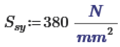
Eccentricity,
Length, L1,
Length, L2,
Factor of safety,
Number of bolts,
Step 1: Permissible shear stress,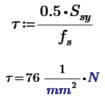
Step 2: Direct shear stress in bolt,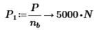
Shear force,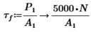
Step 3: Tensile stress in bolt,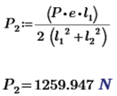
then the bolt1 is subjected to maximum shear force,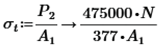
Step 4: Principal shear stress in bolt,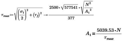
Step5: Size of the bolt,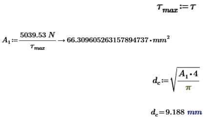
Calculated size of the bolt,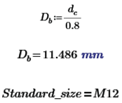
Data Obtained from PSG DESIGN DATA BOOK Pg.no 5.42(For Coarse Series).
3.2. Calculation for Tap Drill Size
Outside diameter, T
Pitch of the thread, P 
Depth of the thread, d
Tap Drill, D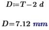
Tap drill can also be worked out when applying the following "Rule of thumb" which is successfully accurate for the most cases
Tap drill size, S
3.3. Calculation of the Screw Clamp
Clamping Force developed:
For screw diameter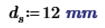
Coefficient of friction, μ
For handle Force to be applied, F
Length of the bolt, L
Step1: Torque required to raise the load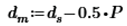
Mean Diameter,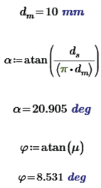
For Isometric Trapezoidal Thread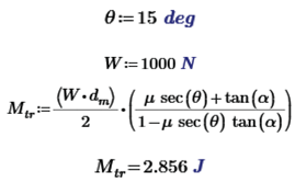
Step 2: Torque required to lower the load
Step 3: Efficiency of the Screw:
Step 4: Overall efficiency of the clamp
Collar Torque; By Uniform pressure theory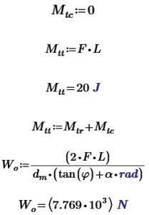
4. Fabrication
A rectangular base of mild steel plate to support all of the components. The surface of the plate is machined with a surface grinding machine. The base plate is drilled with holes to hold the fixture elements in place. The baseplate is robust enough to bear machining force. Screw clamps are sometimes known as clamping screws. This clamping applies pressure directly to the workpiece's side faces. There is a floating pad at their end that serves the following purposes: (a) It prevents workpiece movement and slippage. (b) It prevents denting in the clamping area of the workpiece. (c) The supplied cushion prevents the screw from deflecting. The cylindrical block is machined and bored, and then a screw is inserted. Thus, a screw clamp is made. Locators are utilized to locate the smooth machined surfaces of the component. Locators are built of mild steel. The bolt is composed of carbon steel, having a tensile strength of 480 MPa. The yield strength of the bolt material is used to calculate the diameter of the bolt. The locators are linked to the base plate using an M12 X 1.25 mm bolt. This fixture is capable of machining a variety of workpiece.
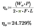
Figure 2.
Design of Adaptable Fixture System.
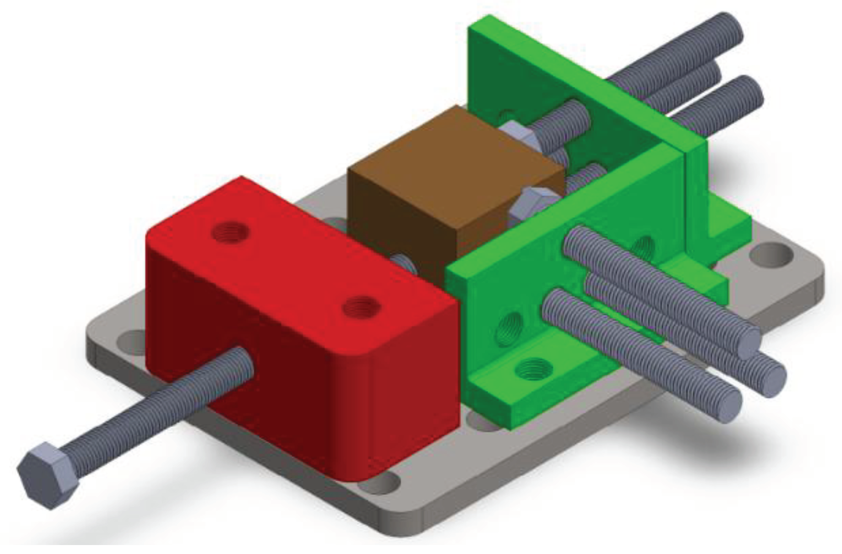
Figure 3.
Fixture System in Drilling Machine.
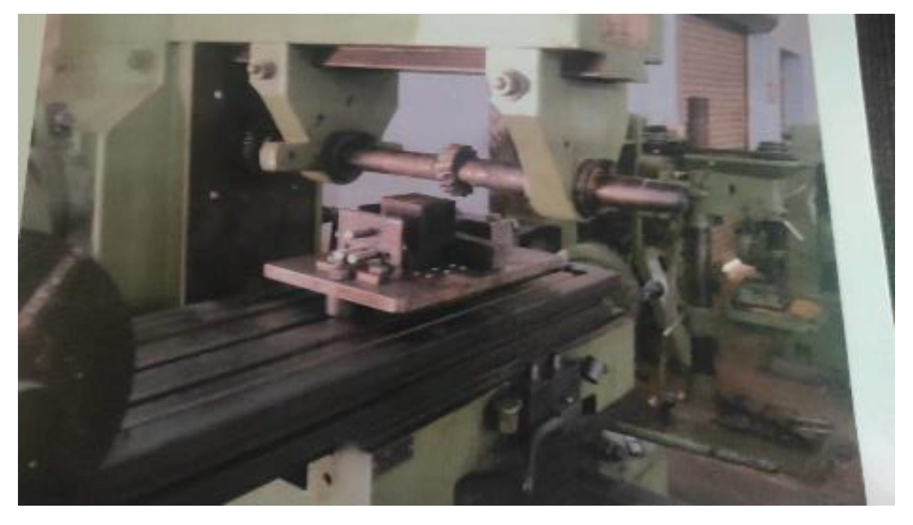
Figure 4.
Fixture System in Milling Machine.
5. Discussion
The flexible fixture designed and manufactured for milling, drilling, and shaping operations can greatly improve the efficiency and dependability of mass production systems. By reducing cycle time for part loading and unloading, the fixture can increase overall system performance while simultaneously cutting production costs. The research findings imply that future improvements in fixture design can be realized by leveraging modern design tools such as CAE and CAD. These instruments can aid enhance fixture arrangement and clamping pressures, reduce deformation, and ensure manufacturing uniformity. The experiment findings are congruent with existing literature on jigs and fixtures, which highlights their value in manufacturing duplicate and interchangeable parts in mass production systems. The adaptable fixture created and manufactured in this project exhibits a revolutionary approach to fixture design, where each fixture is suited to a specific part or form, and its primary function is to identify and keep a workpiece during an operation. The project was hindered by a number of circumstances, including limited resources and time. Future research could solve these restrictions by dedicating extra resources and time to fixture design and fabrication. Furthermore, future study could investigate the use of sophisticated materials and manufacturing techniques to improve the performance and dependability of flexible fixtures in mass production systems.
6. Conclusion
The Adaptable method increased the efficiency and dependability of the fixture design, making the output more realistic. This method can assist minimize the cycle time required for loading and unloading parts. If contemporary CAE and CAD are used to develop the systems, significant gains can be predicted. To meet the multifunctional and high-performance fixturing criteria, the optimum design approach can be applied to conduct extensive assessments and determine an overall perfect design. Fixture layout and dynamic clamping forces optimization approaches based on optimal fixture layout were more efficient in minimizing and uniforming deformation. The proposed fixture will achieve the researcher's output targets while enhancing efficiency.
References
- Shailesh, S. Pachbhai, Laukik P..Raut “A Review on Design of Fixtures” International Journal of Engineering Research and General Science Volume 2, Issue 2, Feb-Mar 2014 ISSN 2091-2730.
- Guohua Qin, Weihong, Zhang Min Wan “Analysis and Optimal Design of Fixture Clamping Sequence ASME for publication in the journal of manufacturing science and engineering, 2006.
- Michael Stampfer “Automated setup and fixture planning system for box-shaped Parts” International Journal of Advance Manufacturing Technology 45:540–552, 10.1007/s00170-009-1983-1, 2008.
- Djordje Vukelic, Uros Zuperl & Janko Hodolic “Complex system for fixture selection, modification, and design” International Journal of Advanced Manufacturing Technology 45:731–748.
- Weifang Chen, Lijun Ni & Jianbin Xue “Deformation control through fixture layout design and clamping force optimization” International Journal of Advanced Manufacturing Technology 38:860–867.
- J. Cecil “A Clamping Design Approach for Automated Fixture Design” International Journal of Advanced Manufacturing Technology 18:784–789,2008.
- Nicholas Amaral · Joseph, J. Rencis · Yiming (Kevin) Rong “Development of a finite element analysis tool for fixture design integrity verification and optimization” International Journal of Advanced Manufacturing Technology 25: 409–419, 2005.
- Y. Wang, X. Chen. N, Gindy “Surface error decomposition for fixture development” International Journal of Advanced Manufacturing Technology.
- Shrikant.V.Peshatwar, L.P Raut “Design and development of Fixture for eccentric shaft: A Review” International Journal of Engineering Research and Applications (IJERA) ISSN: 2248-9622 Vol. 3, Issue 1, February 2013.
Figure 1.
Available Degree of Freedom of Rectangular.
Disclaimer/Publisher’s Note: The statements, opinions and data contained in all publications are solely those of the individual author(s) and contributor(s) and not of MDPI and/or the editor(s). MDPI and/or the editor(s) disclaim responsibility for any injury to people or property resulting from any ideas, methods, instructions or products referred to in the content. |
© 2024 by the authors. Licensee MDPI, Basel, Switzerland. This article is an open access article distributed under the terms and conditions of the Creative Commons Attribution (CC BY) license (http://creativecommons.org/licenses/by/4.0/).
Copyright: This open access article is published under a Creative Commons CC BY 4.0 license, which permit the free download, distribution, and reuse, provided that the author and preprint are cited in any reuse.


