
Submitted:
27 February 2024
Posted:
05 March 2024
Read the latest preprint version here
Abstract
The study of emission, propagation, and reflection of balls in Newtonian mechanics, employing the laws of conservation of momentum and energy when the mass of balls converges to zero, concludes that the kinematics of light is like that of massless balls. The kinematics of light explains why light speed is the constant in each inertial frame in which the light source and reflective mirror are at rest, why the laws of physics have the same form in each inertial frame, and why any experiment in an inertial frame cannot prove the motion of that the other inertial frame. The theory of special relativity misapplies symmetry observed in phenomena to two inertial frames; therefore, it duplicates a physics phenomenon from one inertial frame, considered stationary, into another. Moreover, Lorentz’s transformation offers light speed at the constant in the moving and opposite direction of the inertial frame but is variable in any other direction. Therefore, the theory of special relativity rejects itself with these unacceptable conclusions.
Keywords:
kinematic of balls
; kinematics of light
; geometrical optics
; emission of light
; dragging of light
; propagation of light
; reflection of light
; speed of light
; observation of light
; dragging of light by moving mediums
; Lorentz’s transformation
; special relativity
1. Introduction
The kinematics of balls are independent of their mass. However, their kinetics depend on it because the energy consumed to change their states is proportional to their mass. Suppose a carrier moves balls with different masses from rest to a velocity . The carrier consumes energy for itself and different energy for each ball according to their mass. At velocity , the carrier and balls continue traveling independently from one another and without consuming energy. The energy the carrier consumes to get to velocity is stored proportionally in the carrier and each ball, in the form of momentum according to their mass. At the limit when the mass of balls converges to zero, hypothetical massless balls have the same velocity without consuming energy and without having momentum. Suppose the carrier has a source that emits balls of different masses at a velocity when the carrier is at velocity . The balls with mass or massless will have the same velocity given by the vector sum of velocity and . Therefore, it is rational to compare the kinematics of light with that of massless balls, whose velocity depends on the source velocity and emitted velocity . We call this dependency the dragging of balls emitted at velocity by the source velocity . For light, we have the dragging of light emitted at velocity of electromagnetic nature by the source velocity of mechanical nature. The law of dragging of bodies and electromagnetic radiation created by bodies is based on this simple understanding.
2. Kinematics of Balls
2.1. Balls from Rest Brought to a Velocity
A constant force acts on a ball of mass with a constant acceleration in a straight line of length from rest to a speed . In time , while the speed of the ball increases from zero to , the inertial force of the ball acts with the same magnitude in the opposite direction of force , which changes its state. Energy consumed to overcome is given by the mechanical work created by the force , . While the ball is moved from rest to speed , it gains energy stored in its momentum , which opposes any force that would change its new state. Indeed, the integral of momentum , as a linear function with the constant slope and variable , from zero to , gives the energy gained by the ball of . The ball continues to travel at velocity when the force stops.
Suppose a carrier with balls of different masses stops at velocity . In that case, all balls continue traveling independently from the carrier and one another with velocity , regardless of their mass, including hypothetical massless ones. Differently from balls with mass, the massless balls travel from rest to speed without energy consumption, , without a force, , to act upon them, and without momentum after that, . Massless balls need a carrier that only consumes energy for itself.
2.2. Elastic Collision of Two Balls Moving in Opposite Directions
In the absolute frame, two balls, one of mass traveling at speed and another of mass traveling at speed, are engaged in a frontal elastic collision, as in Figure 1. The speeds of balls after the collision are and, respectively. The equations for the law of conservation of momentum and energy of the balls before and after collision are:
The two equations yield the solution for speed and speed:
and
If , the simplified solutions are and, given with approximation. The solutions are offered without considering the direction of velocities and . For , the direction of and are as in Figure 1. Considering the direction of positive, the direction of is negative, and the direction of and are positive. Therefore, the simplified solutions with approximation are and. At the limit when is zero/massless, the simplified solutions are , and .
When the ball of mass travels in the opposite direction, the simplified solutions for massless balls are and , considering the same positive direction.
Nevertheless, massless balls respect the equation for the law of conservation of momentum , and the equation for the law of conservation of energy . According to these two simplified laws, there is no energy consumption to change the state of massless balls, and massless balls do not have momentum.
A wall can replace the ball of mass to study the reflection of balls with mass or without mass in any direction. The solution for massless balls indicates that adds once to and adds twice. In the wall’s inertial frame, the incident speed of massless balls concerning the wall is , where is the speed of the wall in the opposite direction of ; in the case of Figure 1. The reflected speed of massless balls in the inertial frame of the mirror at the instance of collision is . In the absolute frame, the reflected speed of massless balls is , where is the speed of the wall in the direction of the reflected massless ball; in the case of Figure 1. Equation
offers massless ball speeds in the absolute frame for different wall inclinations. Speed and vary with the inclination of the wall and the incident velocity of massless balls to the direction of velocity . Equation (3) is independent of balls’ mass and applies with approximation to balls with mass in an elastic collision when . Equation (3) also applies to the reflection of light by a moving mirror. [1,2,3]
2.3. Elastic Reflection of a Ball by a Moving Wall
Figure 2 illustrates in the absolute frame a wall W traveling at velocity and a ball traveling at velocity , which hits the wall in an elastic collision; the wall’s mass is much greater than the ball’s mass . The wall reflects the ball at , which is the instance of point of the moving wall in the absolute frame at collision. The ball’s reflection in the inertial frame of the wall only at the instance of collision of has the incident and reflected angles equal measured from the normal to the wall at the point of collision .
This section employs Eq. (3) , in which the reflected speed of the ball in the absolute frame replaces and the speed of the ball replaces .
In the absolute frame, the speed of the wall in the opposite direction of the incident ball is , and the speed of the wall in the direction of the reflected ball is . A detailed form of Eq. (4) is
where angles and are measured counterclockwise from velocity .
In the absolute frame, the wall moves in one direction, but the wall inclination reflects a ball in multiple directions. The ball’s velocity in the mirror’s inertial frame is , given by the vector difference of velocity from velocity . The velocities triangle applies to the ball at any time. On another scale, represents the momentum triangle.
2.4. Emission, Propagation, and Reflection of Balls in the Absolute Frame and an Inertial Frame
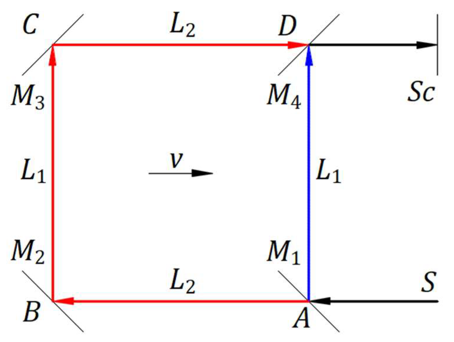
Figure 3 illustrates a ball source at rest and another in motion. In the absolute frame , the source at rest emits a ball at “instant” velocity in direction at an angle from axis . At point of a wall at rest, the ball is reflected in an elastic collision with velocity . Before and after reflection, the ball has the momentum . The ball is at point after a time from the instance of emission at .
In the inertial frame, , traveling at velocity , a source of balls in origin and a wall identical to those in the absolute frame are at rest. The source emits a ball at “instant” velocity in direction at an angle from axis . The energy stored in the momentum of the emitted ball is as in the absolute frame. The ball moves at velocity given by the vector sum of emitted velocity and source velocity . The velocity drags the ball from the projected path at emission, , on another path, , at velocity . The dragging of a ball does not change the direction and magnitude of the emitted velocity , only its propagation direction. Speed for this geometry. At point , the ball is at , the ball traveled the path at velocity , and the direction makes an angle from axis . At , the ball travels in the inertial frame as in the absolute frame. If the source emits other balls between and , all these balls are on the path .
In the inertial frame, in an elastic collision, the wall perceives only the magnitude and direction of velocity . Hence, the momentum because, at collision, the ball’s velocity relative to the wall is . The incident and reflected angle are measured from the normal to the wall at the point of collision to the incident and reflected velocity . After reflection, velocity keeps the same direction and magnitude. The ball moves at reflected velocity given by the vector sum of reflected velocity and velocity . Therefore, the velocity drags the ball from the projected direction of reflected velocity on another path, , at velocity . After reflection, the propagation speed for this geometry.
At point , the ball is at , traveled the path and the path at velocity in time as in the absolute frame.
The reflection phenomenon is identical for any magnitude of incident velocity regardless of ball mass, including massless ones for which there are no forces of action and reaction between ball and wall.
We can conclude that:
- In the inertial frame of a source, a ball is emitted in the absolute frame with its particular direction at speed independent of source velocity. Velocity of a source drags the emitted ball, changing its propagation direction to given by the vector sum of velocity and emitted velocity .
- In the inertial frame of a source in which a wall is at rest, velocity of a source drags the reflected ball, changing its propagation direction to given by the vector sum of source velocity and reflected velocity .
- In the source’s inertial frame, the physics phenomena of emission, propagation, and reflection of balls, with or without mass, are the same as in the absolute frame when the source is at rest. When the wall is at rest in the source’s inertial frame, the ball’s speed in the source’s inertial frame is its emitted speed, .
Newtonian mechanics is based on observations and experiments, which are rationally understood and formulated in laws to be applied with the same rational understanding to experiments, phenomena, and the needs of everyday life. However, Newtonian laws say nothing about observations of phenomena.
3. Kinematics of Light
The kinematics of light as a mechanical phenomenon arises from a series of articles [1,2,3,4,5,6,7,8,9,10,11,12] about the emission, propagation, and reflection of light as mechanical phenomena applied to a few fundamental experiments. The reflection of light as a mechanical phenomenon [1,2,3] was the first step, and the experiment on the reflection and emission of light [12], summarized in Appendix A, was the turning point towards the kinematics of light.
The electromagnetic theory offers the kinetics of electromagnetic wave radiation and the speed of light in a vacuum when the source is at rest in the absolute frame. We study the kinematics of light in the natural interactions of electromagnetic radiation with matter, such as at emission with its source, reflection with a mirror, refraction through a transparent medium, solid or liquid at rest or in motion, and others. The speed of light behaves similarly to the speed of ball from Section 2.3. and Section 2.4.
3.1. Reflection of Light by a Moving Mirror
Unlike References [1] and [2], the same article, Figure 4 illustrates the absolute frame in which a mirror M travels at velocity and a source S of coherent light is at rest.
This section employs Eq. (3) , in which the reflected speed of light in the absolute frame replaces and speed of electromagnetic nature replaces .
In the absolute frame, the speed of the mirror in the opposite direction of incident light is , and the speed of the mirror in the direction of reflected light is .
A detailed form of Eq. (6) is
where angles and are measured counterclockwise from velocity . In the absolute frame, the mirror moves in one direction, but the mirror inclination reflects light in multiple directions.
After a second from the initial instance at , the wavefront is at , and the mirror is at . The wavefronts reflected between and travel in the absolute frame in the direction at velocity . In the absolute and mirror’s inertial frames, the wavefronts travel from to , forming the light propagation as a continuous ray at velocity , wavelength , period , and frequency . A local observer at sees the light coming from emitted at speed , wavelength , period , and frequency . In the absolute frame, the mirror moves in one direction, but its inclination reflects light in multiple directions.
In References [1] and [2], the source is at rest in the inertial frame of the mirror, and the velocity of light is considered independent from the velocity of its source. The light ray reflected at point comes from one point of source. In Figure 4, wavefronts reflected in point of the mirror belong to rays sequentially coming from the source.
3.2. Kinematics of Light as a Mechanical Phenomenon in Inertial Frames
Unlike Newtonian laws, we employ the expressions “observer in the absolute frame” and “observer in an inertial frame,” meaning that the observer is hypothetical and knows/oversees the phenomena in that frame. These terms may be eliminated and state how the phenomena are to be consistent with mechanics. However, the expression “local observer” must remain. A local observer perceives the phenomena by light coming directly from a source, reflected by objects from the observer’s frame or others, and partially reflected rays of a light beam traveling in a transparent medium such as air. In a vacuum, a beam of light is invisible, except when it comes directly to the human eye. Furthermore, the human eye observes only the light emitted from a source and its reflection in a mirror. Therefore, the physics phenomena are perceived by a local observer differently from reality given by Newtonian laws. Nevertheless, we may know reality better by applying Newtonian laws and local observation of light.
The study of emission, propagation, and reflection of light is based on that of balls, as described in Section 2.4. In light case, velocity of mechanical nature is the same as is for balls with mass or massless balls. Emitted velocity , as defined by Maxwell’s equations, replaces emitted velocity , wavefronts propagation velocity from source given by the vector sum of velocities and replaces propagation velocity , and wavefronts propagation velocity from a mirror given by the vector sum of reflected velocity and velocity replaces propagation velocity .
Figure 5 illustrates an inertial frame traveling in the absolute frame at velocity . In the absolute frame , a light source emits a wavefront at velocity in direction at an angle from axis . At point , a mirror reflects the wavefront with velocity . After a time from the instance of emission at , the wavefront is at point . The light on the paths and travels at speed , wavelength , period , and frequency .
In the inertial frame, , a source of light at origin and a mirror are at rest. Points and belong to the inertial frame, and their instances in the absolute frame have a corresponding index. At , the source emits a wavefront at velocity in direction at an angle from axis . Velocity drags the wavefront from the projected path at emission, , on propagation path, , at velocity . The dragging of the wavefront does not change the direction and magnitude of its emitted velocity but changes its propagation direction. Speed for this geometry. At point the wavefront is at , the direction makes an angle from axis , and light traveled the path at velocity , wavelength , period , and frequency . The light traveled in the inertial frame at as in the absolute frame.
In the inertial frame in which the source and mirror are at rest, the mirror perceives only the magnitude and direction of emitted velocity because, at collision, wavefronts and mirror have the same velocity . Hence, the wavefront’s velocity relative to the mirror is . The incident and reflected angle are measured from the normal to the mirror at the collision point to the incident and reflected velocity . After reflection, velocity keeps the same direction and magnitude. The wavefront moves at propagation velocity given by the vector sum of reflected velocity and velocity . Therefore, velocity drags the wavefronts from the projected direction of reflected velocity on the propagation path, , at velocity . After reflection, the propagation speed for this geometry.
At point the wavefront emitted from is at , the direction makes an angle from axis , and light traveled the paths and at velocity , wavelength , period , and frequency as the path and , respectively, in the absolute frame. In the inertial frame at point , the wavefront emitted from traveled from to and then to in time as in the absolute frame.
We can conclude that:
- A source at rest in the absolute frame emits waves of light in all directions uniformly distributed in space at speed defined by Maxwell’s equations with wavelength and period . A source in motion emits wavefronts of light in the absolute frame in all directions independent of source velocity at speed . The source velocity drags each of the emitted wavefronts such that the waves in the source’s inertial frame are uniformly distributed in space and travel at speed with wavelength and period , as in the absolute frame.
- In a source’s inertial frame, a mirror at rest perceives only the emitted direction of wavefronts, which are reflected accordingly. The source velocity continues to drag each of the reflected wavefronts, such that the waves travel at speed with wavelength and period in the inertial frame of the source.
- In an inertial frame, the law of dragging applies to bodies at rest and in motion belonging to that inertial frame. The dragging is embedded in the laws of mechanics, including the kinematics of light. It works in the background of inertial frames. It acts on bodies and electromagnetic radiation created by bodies of each inertial frame, making phenomena as in the absolute frame. Therefore, the dragging explains and confirms the principle of relativity, according to which no experiment in an inertial frame can prove the motion of that frame. It explains that the laws of physics have the same form in each inertial frame, including electromagnetic radiation defined by Maxwell’s equations, and that the speed of light is the constant in the absolute and each inertial frame when the source and reflected mirror are at rest in those frames.
- For theoretical studies, it is convenient to compare physics phenomena from inertial frames only to the frame at absolute rest, which is an inertial frame at zero speed. The kinematics of phenomena in each inertial frame are like in the frame at absolute rest. Therefore, each inertial frame can be considered a local frame at absolute rest for phenomena belonging to that inertial frame. To study interactions between physical systems belonging to two inertial frames, one can be considered a stationary/local frame at absolute rest in which another frame travels at the relative speed between the two frames.
3.3. Experiments and Observations that Support Kinematics of Light as a Mechanical Phenomenon
The kinematic of light as a mechanical phenomenon explains different experiments and local observations that supported special relativity due to insufficient and incorrect understanding.
1. Light travels through a transparent medium at a specific constant speed independent of source speed. Michelson and Morley [13] considered their experiment in the fixed ether. Therefore, the emitted light speed and the incident and reflected light speed to a mirror have the same magnitude in the hypothetical ether of the absolute frame. In ether theory, the speed of light is limited by ether. The ether theory predicts a fringe shift, which is not confirmed by the zero fringe shift of the experimental results.
Differently, the kinematics of light demonstrate that in an inertial frame where a source of light and a mirror are at rest, the speed of light emitted by a source is limited at the constant of electromagnetic nature as in Maxwell’s equations. However, the light speed in the inertial frame of the source is the vector sum of velocity and velocity of the source of mechanical nature; emitted velocity remains unaffected by its dragging in magnitude and direction. Therefore, the kinematics of light predicts zero fringe shift for the Michelson‒Morley experiment in agreement with the experimental results.
2. Emission, propagation, and reflection of light in inertial frames [4] explains the experiment performed at CERN, Geneva, in 1964 [14] without rejecting Ritz’s ballistic theory [15]. Figure 6 illustrates the phenomenon in a simplistic approach.
A boson of mass accelerated at a mechanical speed near the constant speed of light decays in a particle of mass and one massless photon. At speed , particle changes its direction, and the photon is moving free at speed . Bosons are only carriers that give photons only their mechanical speed near the constant speed of light . Bosons are not sources of light to give photons the speed of electromagnetic nature on top of speed of mechanical nature. This experiment confirms the dragging of light by source velocity.
3. Figure 7(a) illustrates the observation of a star in the Universe according to the kinematics of light as a mechanical phenomenon. A star at point and Earth at point travel at velocity . At this initial instance, the star emits a wavefront of light in the direction at emitted speed . After a time, the star travels at point and Earth at point the same length , and velocity drags the wavefront emitted in the direction along ; at , a local observer perceives the wavefront coming from . Therefore, the star is seen at its actual location.
Figure 7(b) illustrates the observation of a star in the Universe according to the hypothesis that the speed of light is independent of the motion of the source, as in ether theory. A star at point and Earth at point travel at velocity . At this initial instance, the star emits a wavefront of light in the direction at emitted speed . After a time, the star travels at point and Earth at point the same length , and the wavefront emitted in the direction reaches point where a local observer perceives the wavefront coming from . Therefore, the star is observed at the initial location, not its actual one, which means that the hypothesis of the light speed constancy creates irregularities unobserved by astronomers. These irregularities differ from those de Sitter incorrectly predicted. [16,17]
4. The emission of light as a mechanical phenomenon [4] applies to observing a star’s orbit [5]. Figure 8 depicts the actual star orbit of radius in the plane of the paper and the imaginary circle of radius with its plane parallel to the front of the paper plane. The distance is perpendicular to the orbit and imaginary circle planes. The observer is at point . The observed star orbit of radius is centered at . The view is from the back-right of the observer to have a clear image of the actual and observed orbit.
The distances in each set of ( and (), including all other similar distances corresponding to points , and are equal.
The emitted rays from the star in motion are dragged by the star velocity at the emission point through different paths to a local observer. At point , the star emits a wavefront of light at velocity in the direction that is dragged by velocity along the path at the propagation velocity . At point , the observer sees the wavefront coming from point at speed . At point , the star emits a wavefront of light at velocity in the direction that is dragged by velocity along the path at the propagation velocity . At point , the observer sees the wavefront coming from point at speed . The same observation occurs for each point of the circular orbit.
Points , and give the corresponding points , and that form the observed orbit with the center in for this particular case. The local observer sees the star’s orbit rotated with a bigger diameter than the actual orbit. The speed of light from any point from the observed orbit to the observer is the constant . Therefore, no time irregularities exist to reject Ritz’s ballistic theory, [15] as de Sitter predicted, [16,17] and observing the star’s orbit supports the kinematics of light as a mechanical phenomenon. This study is an example of the phenomenon of an actual star orbiting and how a local observer views the observed orbit.
5. Emission, propagation, and reflection of light as mechanical phenomena applied to the Michelson interferometer with sunlight as a source [8,9] in Miller’s experiment [18] at Cleveland Laboratory in 1924 are explained; the fringe shift is in the order of . [8,9]
Miller mainly employed light from local sources in his experiments. The kinematic of light [4] predicts zero fringe shift for any altitude location on Earth’s inertial frame. The experiments with local sources at Cleveland Laboratory in 1924 are explained by Reference [4]. At Mount Wilson at high altitude, where experiments were performed with local sources, the fringe shift of 0.08 in 1921 and 0.088 in 1925 remain unexplained.
In Reference [8], the author incorrectly considered that the experiments at Mount Wilson employed sunlight, which explains the fringe shifts of 0.08 and 0.088. The mistake was caught later in the review process. [9] If there is no theoretical explanation, the attention may return to the ambiance of experiments and, in particular, to the device’s temperature uniformity.
6. Majorana’s experiment [19] in Earth’s inertial frame employs a fixed light source. The light travels through three stages, each consisting of one movable and one fixed mirror, and enters a Michelson interferometer with unequal-length arms. The movable mirrors are fixed on a rotational disk in both directions. When the disk is at rest, a fringe image is observable. When the disk is rotated from the maximum speed of one direction to another, a shift of 0.71 fringes is observed [19]. Like the Michelson interferometer, Majorana’s experimental device remains an outstanding contribution to the physics of light despite changes in experiment interpretation with time. Majorana misunderstood the phenomenon within the device and the significance of the fringe shift observed at the experimental time, explaining the fringe shift favorably to special relativity. The reflection of light as a mechanical phenomenon [1,2,4] applied to the Majorana experiment [10] shows that the speed of light changes after each stage, causing the fringe shift in the Michelson interferometer. Reference [10] approximates rotational mirrors as inertial frames and derives a shift of 0.27 fringes. However, the observed shift of 0.71 fringes confirms the kinematics of light as a mechanical phenomenon and rejects the constancy of light.
7. Besides interactions of emission and reflection of light with matter, another example is the refraction of light when it travels from one medium to another at rest, according to Snell’s law. Airy’s experiment is an example of the dragging of light by a moving medium. Airy [20] expected to adjust the telescope’s inclination after introducing a tube with water along its axis, but that was unnecessary. Considering the dragging of light by the moving water and the experiment result, we obtained the Fresnel dragging coefficient from a mechanics perspective, [11] where is the medium’s refraction index.
3.4. Galilean Transformation
We study Galilean transformation as in mechanics, where physics phenomena are as they are and without observations.
All inertial frames extended to infinite overlap. The phenomenon in an inertial frame is shared instantly in any other inertial frame. The inertial frame in which a phenomenon is to be shared is considered at relative rest/stationary frame.
Galilean transformation offers how a physics phenomenon, including emission, propagation, and reflection of light as mechanical phenomena, is shared instantly from a stationary frame in an inertial frame. Figure 9 depicts a stationary frame in which an inertial frame travels at relative velocity along the axis, and the planes and coincide.
The kinematics of light prove that in a stationary frame, light rays from a source at rest are uniformly distributed and travel at speed ; we do not assume these phenomena.
Origins and coincide at the initial instance when the source belonging to origin of the stationary frame emits a spherical wavefront of light formed by individual ray wavefronts. After a time , the spherical wavefront of light has its center at , and the origin of the inertial frame is at at a distance from . Galilean transformation offers the coordinates of each ray wavefront on the spherical wavefront. Figure 9 shows at a time the ray wavefronts at points , , , and on the circular wavefront in plane and their coordinates in plane .
The ray wavefront emitted in direction at the initial instance travels in this direction at all times, and it is at all times on this spherical wavefront, which enlarges continuously. This ray wavefront travels length in the inertial frame at the propagation velocity . The vector difference of vector and vector gives velocity illustrated at points and . This ray wavefront travels at the same angle and velocity for any other instance of the spherical wavefront. This process is identical for each ray wavefront on the spherical wavefront. However, velocity of ray wavefronts varies with angle . Therefore, the directions of the ray wavefronts are not uniformly distributed in the space of the inertial frame. The ray density increases from to .
Galilean transformation, in its simplest form, consists of four equations applicable to each ray wavefront of a spherical wavefront:
Figure 9 and the Galilean transformation apply identically to a hypothetical ball source when the source emits a spherical ball front and the speed of balls .
Figure 9 may be deceiving. It may suggest that the spherical wavefront also belongs to the inertial frame, which is incorrect. The set of Eqs (8) gives just the location of coordinates of the spherical wavefront in the inertial frame at a time . The phenomenon of light propagation of the physical system consisting of a source and spherical wavefront belongs to the stationary frame. The source, which has its coordinate , and the spherical wavefront do not belong to the inertial frame. A phenomenon in an inertial frame is unique in the Universe and instantly shared in each inertial frame, not duplicated. The laws of physics have the same form in each inertial frame, and the phenomenon of a stationary frame is independent of any other inertial frame. There are no transformations of phenomena from stationary frame to inertial frame to undergo changes that may or may not affect the physics laws of those phenomena. The term transformation may be inappropriately used. It may suggest that a phenomenon obeys rules, laws, or hypotheses to be transformed from one inertial frame to another when it is a simple sharing. A better wording may be Galilean coordinates.
4. Einstein’s Theory of Special Relativity
4.1. Introduction
In the first paragraph on page one of his manuscript “On the electrodynamics of moving bodies,” [21] Einstein says: “It is known that Maxwell’s electrodynamics—as usually understood at the present time—when applied to moving bodies, leads to asymmetries which do not appear to be inherent in the phenomena. Take, for example, the reciprocal electrodynamic action of a magnet and a conductor. The observable phenomenon here depends only on the relative motion of the conductor and the magnet, whereas the customary view draws a sharp distinction between the two cases in which either the one or the other of these bodies is in motion. For if the magnet is in motion and the conductor at rest, there arises in the neighbourhood of the magnet an electric field with a certain definite energy, producing a current at the places where parts of the conductor are situated. But if the magnet is stationary and the conductor in motion, no electric field arises in the neighbourhood of the magnet. In the conductor, however, we find an electromotive force, to which in itself there is no corresponding energy, but which gives rise—assuming equality of relative motion in the two cases discussed—to electric currents of the same path and intensity as those produced by the electric forces in the former case.”
Einstein considers his example asymmetric because when the magnet is at rest, no electric field arises in the moving conductor, and still, reciprocal phenomena occur. He may suggest that observations are enough to accept reciprocal phenomena even if an electromagnetic quantity, like an electric field, does not arise. Therefore, there is no need to understand physics phenomena rationally.
Appendix B shows that in Einstein’s example, when the magnet is at rest, an electromotive force (emf) is created in the conductor in motion, making the conductor an electrical source; therefore, an electric field arises. Thus, Maxwell’s electrodynamics applied to moving bodies leads to symmetries like in other phenomena; each physics quantity involved in a phenomenon arises, and the phenomena can be rationally explainable.
However, can we apply the symmetry of phenomena observed and understood as an equilibrium in reciprocity between two inertial frames? What physics similarities can be among the reciprocal and symmetrical phenomenon between magnet and conductor given by Einstein, or any other symmetrical phenomena, and the phenomenon between two inertial frames, if there is one?
The example has the magnet and conductor in proximity, and they have reciprocal electromagnetic properties. None of these characteristics applies to a stationary and inertial frame to support special relativity. The origins of the two frames depart from one another and are in proximity for a relatively short time. Frames, including the absolute frame, are hypothetical entities. These simple tools help us study and understand physics phenomena. They have no physics properties to transform/duplicate a physical system from one frame to another, not even for observations.
Symmetry applied to two inertial frames, the main idea in special relativity, creates duplications. It is unrealistic and leads to irrational conclusions, as discussed further.
From “Examples of this sort, together with the unsuccessful attempts to discover any motion of the earth relatively to the “light medium,”” Einstein concludes three suggestions in the second paragraph of page 1:
1. “… the phenomena of electrodynamics as well as of mechanics possess no properties corresponding to the idea of absolute rest.”
Einstein rejected the idea of absolute rest, but an inertial frame considered stationary is a local frame at absolute rest. The stationary frame was a convenient choice to present his transformation understanding of a phenomenon between two inertial frames.
2. “… the same laws of electrodynamics and optics will be valid for all frames of reference for which the equations of mechanics hold good.”
The equations/laws of mechanics are valid for the phenomena belonging to an inertial frame, not for the coordinates of phenomena in another inertial frame. Still, opposite to the second suggestion, special relativity forces the laws of electrodynamics and optics to hold good to coordinate observations for which mechanics do not hold good.
3. “… light is always propagated in a vacuum with a definite velocity , which is independent of the state of motion of the emitting body.”
In a stationary frame, without considering the dragging of light, the rays emitted from a source at rest travel at velocity and are uniformly distributed in the inertial frame of the source and the stationary frame. When a source moves at a velocity , the rays travel in both frames at speeds different from , are not uniformly distributed in space, and have their waves deformed. Therefore, there are differences in ray propagation in a stationary frame according to the motion states of sources.
Without understanding the physics phenomenon of his example and missing details from the above suggestions, Einstein chose to make hypotheses based on observations, elevating them to postulates.
4.2. Einstein’s Postulates
From the three suggestions, Einstein formulates two postulates:
1. “The laws by which the states of physical systems undergo change are not affected, whether these changes of state be referred to the one or the other of two systems of co-ordinates in uniform translatory motion.”
2. “Any ray of light moves in the “stationary” system of co-ordinates with the determined velocity c, whether the ray be emitted by a stationary or by a moving body.”
A phenomenon in a stationary frame is independent of each other’s inertial frame, and it is shared instantly, as it is, in each other’s inertial frame. By sharing, the states of physical systems do not undergo change to affect or not their laws of physics. Galilean transformation means just coordinates of a phenomenon from a stationary to an inertial frame. The first postulate forces the coordinates of Galilean transformation to obey the same form of laws of physics applied in inertial frames; this creates a fictive duplication of a phenomenon from a stationary frame into an inertial frame. The first postulate has a broad inclusion, but practically, it is applied to observing light. See comment on Suggestion 2 of Section 4.1.
The second postulate indicates that the details of Suggestion 3 of Section 4.1. were not understood in Einstein’s time.
Einstein applies his transformation when the source belongs to the stationary or inertial frame. When the source belongs to the inertial frame, there is no need for Einstein’s transformation; the phenomenon is already there. For clarity, we consider that the light source belongs to the stationary frame. If the source belongs to the inertial frame, then this frame is considered stationary. Therefore, Einstein’s transformation has one direction: from stationary to the inertial frame. Einstein presents a particular case of his transformation that is identical to a previously well-known Lorentz transformation. [22]
Figure 10 depicts a stationary frame in which an inertial frame travels at relative velocity along the axis, and the planes and coincide. Origins and coincide at the initial instance when a light source belonging to the origin emits rays of light in all directions. After a time , the wavefront of light in the plane is on a circle with the center at , and origin is at distance from .
The conclusion from observations and the Michelson‒Morley experiment was that the speed of light has the constant in each inertial frame. FitzGerald [23], from a misunderstanding of the Michelson‒Morley experiment at his time, wrote: “I would suggest that almost the only hypothesis that can reconcile this opposition is that the length of material bodies changes, according as they are moving through the ether or across it, by an amount depending on the square of the ratio of their velocity to that of light.”
With his transformation, Lorentz presents how the coordinates of the points belonging to the circular wavefront of light from the stationary frame are in the inertial frame. He applied his transformation along the axis , keeping the constancy of light in both directions.
Lorentz’s transformation consists of four equations applicable to each point of the circular wavefront in plane when changes in length occur along the axis in both directions:
where is the Lorentz factor, comparable to the square of the velocity and ratio suggested by FitzGerald.
Substituting at point , is the absolute coordinate in inertial fame, and is the absolute time in which light travels the length at speed . Note that is identical to in Galilean transformation. , , then , which verifies the constancy of light. For s, the length m from the stationary frame undergoes a contraction given by m, which yields m. Because for , the length m is longer than , and point shifts right to . The dilation created by of m is insignificant compared to the contraction created by m.
Substituting at point , is the absolute coordinate in absolute value, and is the absolute time in which light travels the length at speed . , , then , which verifies the constancy of light. For s, the length in absolute value m from the stationary frame undergoes a dilation given by m, which yields m. Because for , the length m is longer than , and point shifts left to . The dilation created by of m is insignificant compared to that created by m.
Note that the dilation created by enlarges the spherical wavefront from that of the stationary frame coordinates to an approximated spherical wavefront. This result is unforeseen, creating a visual duplication, and is a reason to reject Lorentz’s transformation and special relativity. Factor can be ignored without affecting the constancy of light speed and with the observed and coordinates wavefront coinciding.
Distance is the radius of the spherical wavefront in the stationary frame. The coordinate of each point of the spherical wavefront undergoes a change. Then, the coordinate of point at point shifts to the right to point and point to point with . Therefore, the radius becomes radius . At a time , a wavefront travels at point and another at point . At time and for an angle , we can calculate , , , , . In triangle , the radius and the speed along is . The calculation of speed is also correct for negative because for , is negative, and is positive.
Table 1 offers the numerical calculation of the speed function of angle in steps of and for , one second after the spherical wavefront was emitted. We calculated angle by trial and error until speed m/s.
In Table 1, for , m equals that obtained at point with Lorentz’s transformation, but the speed is not constant . Similar for , m equals that obtained at point with Lorentz’s transformation, but the speed is not constant . At any time, are equal only at and for both calculations, respectively, and speed has the same magnitudes as in Table 1, different from constant .
Lorentz’s and Einstein’s transformations keep the light speed constant for the rays in the same and opposite direction to , which was the intent of the transformations, but speed variation of all other spherical wavefronts conflicts with special relativity. The second postulate declares that the speed of light is a constant in any inertial frame, assuming it is in any direction, but the transformation drastically concludes otherwise. Special relativity is self-negating.
4.3. Discussions
1. Is it reasonable to observe the spherical coordinates having its center in origin and to keep the speed of light a constant along axis in both directions to have a theory based on experimental observations without understanding the physics phenomena of those experiments? Furthermore, is it reasonable to force the spherical coordinates and their observation to have the same physics laws as in the stationary frame? This approach, chosen by Einstein, leads to an irrational world. In Newtonian mechanics, the fundamental difference from special relativity is that the laws present the phenomena as they are, not observed, and are rationally understood by themselves, not accepted by hypotheses or postulates. In mechanics, the dragging of bodies and electromagnetic radiation explains even the principle of relativity.
2. What natural phenomena, applied to Figure 10, can transform each ray from the stationary frame in its unique form, as Lorentz’s transformation requires? We can consider other mathematical transformations, as in Section 4.2. ignoring Lorentz’s factor , or the speed of light to be constant along each ray in the inertial frame, or in which time or length is constant instead of light speed, to explain the Michelson‒Morley experiment. [24] Could it be a phenomenon for each of these particular hypothetical mathematical transformations, and which one would be correct? There are no such phenomena. If we try these transformations, we get a theory with irrational conclusions for each, as for special relativity.
3. The manuscript, presentation, and teaching of special relativity are focused on observation. Is Lorentz’s transformation not applicable when there is no light or when a phenomenon is too far to be observable? Observation depends on the perception of light by the human eye. Paragraph one of Section 3.2. describes the limitations of human eye observation. Suppose a source that emits rays of light in a vacuum in all directions. An observer sees only the ray that travels directly to his eyes; all other rays are invisible. No light rays are observed if the observer is at the source location. If the source emits rays in a medium such as air, the particles of the medium reflect some rays, and our eyes may have a limited, deformed, and retarded observation. This discussion raises questions about the validity of time synchronization in special relativity.
4. An observer in the inertial frame needs a ruler identical to that from the stationary frame to measure lengths for phenomena of its frame. In addition, he must have another two rulers with different scales to measure the lengths transformed from stationary frame according to positive or negative. The use of multiple rulers is unacceptable. The same conclusion applies to multiple synchronized clocks.
5. Suppose the inertial frame also has a source at its origin. When the origins coincide, each source emits a spherical wavefront of light. Imagine the confusion of an observer in the inertial frame observing two different spherical wavefronts with the center at .
6. In observing a star, as in Example 4 of Section 3.3., which involves astronomical distances, we see the star in an enlarged orbit without irregularities, but our observation does not change the actual orbit. There is no need to mention other observations close to our eyes that we know they are not factual. The observations are explainable through the law of physics, but we must distinguish between the phenomena and how our eyes observe them. Therefore, we cannot rely only on observations. Special relativity talks about observation, but it does not consider that our eyes perceive only the direction of rays emitted by the source and reflected by mirrors, not the direction of rays’ propagation. Therefore, this is another fact not understood at that time.
7. Lorentz struggled to explain the Michelson‒Morley experiment because, at his time, the law of dragging of light was not understood or accepted. However, W. Ritz [15] offered the ballistic theory of light, similar to the concept of dragging of light, but De Sitter’s [16,17] observations of binary stars rejected it. Lorentz gave an explanation [22] that set the physics on the wrong path. Section 4.2. gives different times when light travels the length at speed in the direction and opposite. at is longer in absolute value than at . Therefore, the main reason for Lorentz’s transformation to explain the Michelson‒Morley experiment failed without considering the light traveling along the axis. Special relativity follows the same approach with a broader view but the same result.
8. Figure 10 illustrates a case when the origins and coincide. However, when the source emits light rays at an initial instance, the origin may be far away from . In this case, there are times when the spherical wavefront does not include origin , there is a time at which the spherical wavefront is at origin , and there are times when the spherical wavefront includes origin . How is the initial wavefront observed at at a different time ? Do we force the coordinates of the spherical wavefront to be observed according to Lorentz transformation with its center at at any time ?
9. Suppose that the light source is a ball source and emits balls of equal mass in all directions at a speed higher than the speed of the inertial frame . As for light, Galilean transformation gives the coordinates of the spherical ball front in the inertial frame at a time as they are. Mechanics does not and cannot force the coordinates of the spherical ball front to have its center at ; or, in Einstein’s words, the equations of mechanics do not hold good in this case. Moreover, the mechanics exclude observations. Special relativity does not respect Suggestion 2 of Section 4.1. Thus, this is a reason to reject special relativity.
10. For the ray wavefront along the axis of Figure 10, the magnitudes , , , , and are directly proportional to time and the speed of light is constant at any time. Suppose the source emits a wavefront at the second instance after the initial one when the distance . In this case, the length is also directly proportional to time . At a time after the second instance, and all other magnitudes keep the same form. The variation of with the distance indicates that the quantities , , and are also variable, confirmed by numerical calculation. Therefore, for each other wavefront, the length undergoes different contractions and the length has different magnitudes, which means that each wavefront requires its ruler and time synchronization. Moreover, the length measurement and time synchronization are unachievable even if the constancy of light is respected.
11. The first postulate indicates that physical systems from the stationary frame change when transformed/duplicated into the inertial frame. A physical system mentioned in the first postulate may have a source and wavefront, but it may contain bodies, living beings, and observers involved in a phenomenon. Imagine what duplicating the physical systems from a stationary frame means in all other inertial frames. Moreover, each inertial frame, arbitrarily, may be stationary; therefore, all physical systems from each inertial frame are transformed/duplicated in all other inertial frames. All these duplications are irrational and not observed at the Universe or local scale.
12. In a stationary frame, as in Figure 10, the origin of the inertial frame may travel through a few consecutive points of axis . Suppose a phenomenon arises in the stationary frame when the origin coincides with each consecutive point. Each of these phenomena is transformed in origin . Imagine all these phenomena involving bodies and living beings at ’s location. Let us note that Galilean coordinates do not eliminate collisions between phenomena of different inertial frames, but these collisions are rational, understandable, and explicable.
5. Conclusions
Lorentz’s and Einstein’s transformations have multiple issues. A few of them are listed below. The transformations:
- -
- are based on observations,
- -
- duplicate physics phenomena, and
- -
- give the constancy of light only along the direction of inertial frame movement and generalize this result for all other directions.
The saga of special relativity started with FitzGerald’s mention that the length of material bodies changes, based on the misunderstanding of the Michelson‒Morley experiment. Lorentz continued it with his transformation, Einstein with an entire theory, and many others. Special relativity should not have been written and accepted.
The kinematics of light as a mechanical phenomenon is based on Newton’s laws, which are evident and do not need explanations. They are explained by themselves. The mechanics’ law of dragging can be extended to electromagnetic radiation for different situations:
- Rays of light are emitted at velocity in the absolute frame and dragged by velocity of their source, such as in source inertial frame rays are uniformly distributed in space and travel at velocity . [4]
- A mirror at rest in the source inertial frame perceives only velocity of emitted rays and reflects them in the absolute frame accordingly; source velocity drags the reflected rays at velocity , such as in source inertial frame, reflected rays travel at velocity . [4]
- Light propagation in each inertial frame is like in the absolute frame. Therefore, no experiment in an inertial frame can prove the motion of that inertial frame. If the source and mirror are at rest in an inertial frame, the rays of light travel at emitted velocity like in the absolute frame when the source and mirror are at rest. Each inertial frame for all its phenomena is like a local absolute frame.
- We study the kinematics of light at the emission of light in the source inertial frame and the reflection of light in the mirror inertial frame. When a source and mirror have different velocities, the reflection of light is more complex depending on the mirror and source velocity and whether the mirror perceives the velocity of the source relative to the mirror or not. [7]
- In the interaction of light with a moving medium, the medium drags the light according to Fresnel’s dragging coefficient , also derived from a mechanics perspective, [11] where is the medium’s refraction index.
Special relativity focuses on observations of phenomena instead of how phenomena are, as mechanics do. Different from the two approaches, the kinematics of light presents how the phenomena are as in mechanics and how a local observer perceives the phenomena, which helps to know reality.
Matter creates light, and the kinematics of light as a mechanical phenomenon presents light naturally in its interaction with matter at emission and reflection, [1,2,3,4,5,6,7,8,9,10] refractions, [11] and others. Light and any other kind of electromagnetic radiation, which consists of an electromagnetic field, can be considered massless matter/field and included in mechanics.
Appendix A
Michelson derived the fringe shift in his interferometer employing the ether theory. The Michelson‒Morley experiment [13] expects to give a fringe shift. The experimental result is less than the theoretical one enough to consider it a failure. References [1,2], which are the same paper, derive the fringe shift for a particular geometry of the Michelson‒Morley experiment in which the beam splitter makes an angle of with source rays, one opaque mirror is perpendicular, and another one is parallel to source rays. In this case, the expected fringe shift also is .
References [1,2] derive the speed of light reflected by a moving mirror for any angle measured from velocity of the mirror to velocity of incident light and for any inclination of the mirror; the light source is at rest in the inertial frame of the mirror. The speed of light is considered independent of the light source, as in ether theory. In this setting, the geometry of the Michelson‒Morley experiment predicts a fringe shift and the particular geometry predicts a zero fringe shift. These theoretical results satisfy the experimental ones. To confirm or infirm this conclusion, we looked for another interferometer.
Figure 11 illustrates this interferometer. [12] The light source splits on beam splitter . The transmitted rays travel from to opaque mirrors and , beam splitter , and screen . The reflected rays travel from to beam splitter and then to screen . All four mirrors make an angle of with the incoming rays.
Figure 11.
Schematic of the interferometer.
Rotating the interferometer in the inertial frame of the mirror in steps of , the theoretical fringe shift is ; [12] this predicted high fringe shift leaves no uncertainty about the experimental result of the zero fringe shift. Therefore, the combination of light reflection as a mechanical phenomenon that is not correct in ether theory and the speed of light considered independent of source speed as in ether theory is incompatible. If we apply ether theory to this interferometer, the theoretical fringe shift is zero according to the experimental result.
The ether theory and the combination of the two hypotheses predict theoretical results that are inconsistent with experimental results. This conclusion makes us consider the emission and reflection of light mechanical phenomena. The kinematics of light as a mechanical phenomenon explains the Michelson‒Morley experiment and others as presented in this paper.
Appendix B
In the magnetic field of a fixed magnet, Lorentz’s electromagnetic force is given by the cross product , where is the velocity of a positive or negative electrical charge and, at the same time, the velocity of that charge relative to the magnet. When electrical charge is at rest, and the magnet is in motion at velocity , the velocity of the charge at rest relative to the moving magnet is , as well. Considering the relative velocity of the electrical charge in motion or at rest to the fixed or in motion magnet, respectively, Lorentz’s electromagnetic force keeps the same form, . Otherwise, considering the magnet velocity , Lorentz’s electromagnetic force is .
The expression has the units of , which in physics quantities means that is the total electrical charges in a conductor of length through which flows a constant current . Therefore, when the magnet is fixed, Lorentz’s force becomes , where is the current vector with the direction of positive charges flow. Lorentz’s electromagnetic force is when the magnet is in motion and the conductor is fixed.
Lorentz’s right-hand rule and Fleming’s right-hand and left-hand rules are replaced with the following rule: The known quantity associated with movable conductor/magnet rotates in the short direction over the known quantity associated with fixed magnet/conductor yields the direction of Lorentz’s force.
Figure 12(a) shows a magnet with its magnetic field perpendicular to and toward the paper and a conductor that can be connected to an electric current source. The magnet and conductor are in equilibrium when they are at rest relative to each other, and no current flows through the conductor.
Suppose the magnet is fixed, and the conductor, which has a degree of freedom horizontally in both directions, connects to the source. The source electric field forces the current to flow through the conductor in the direction from top to bottom. The interaction between the magnetic field and the current produces an electromagnetic force of reciprocal repulsion between conductor and magnet. Lorentz’s electromagnetic force . In this case, of the movable conductor rotates in the short direction over of the fixed magnet to find the direction of reciprocal repulsive electromagnetic force that moves the conductor to the right in another state of equilibrium.
Figure 12.
(a) Charged conductor in a magnet’s magnetic field. (b) Moving a conductor or magnet when they are in proximity.
Figure 12.
(a) Charged conductor in a magnet’s magnetic field. (b) Moving a conductor or magnet when they are in proximity.
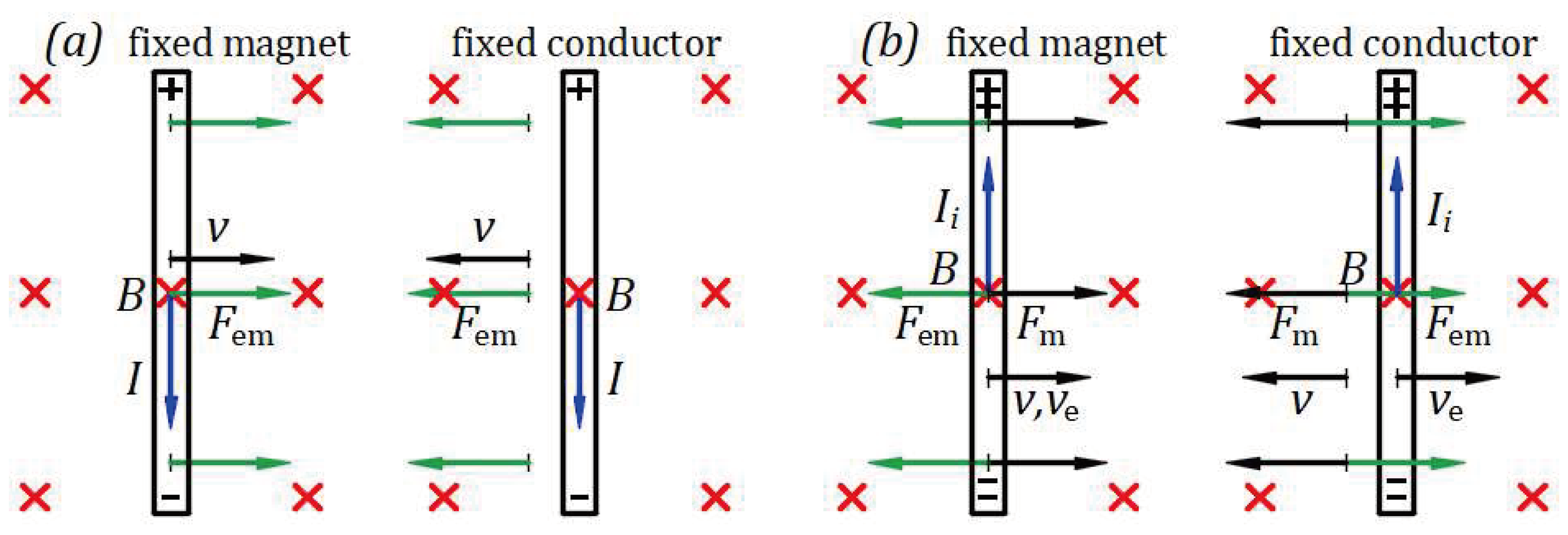
Suppose the conductor is fixed and the magnet has a degree of freedom horizontally in both directions. Connecting the conductor to the source, the source electric field forces the current to flow through the conductor in the direction from top to bottom. The interaction between the magnetic field and the current produces an electromagnetic force of reciprocal repulsion between conductor and magnet. Lorentz’s electromagnetic force is . In this case, of the movable magnet rotates in the short direction over of the fixed conductor to find the direction of reciprocal repulsive electromagnetic force that moves the magnet to the left in another state of equilibrium.
Considering the motion of the conductor relative to the magnet, the conductor moves to the right, and the motion of the magnet relative to the conductor, the magnet moves to the left. Employing both relative motions explains the reciprocity of phenomena.
Figure 12(b) illustrates Einstein’s example. A magnet at rest or in motion does not create an electric field without a conductor. The magnet and conductor must be in proximity, and one must be in motion. An electric field arises in a conductor at rest in the neighborhood of a moving magnet, and, opposing to Einstein’s understanding, an electric field also arises in a moving conductor in the neighborhood of a magnet at rest, resulting in a reciprocal and symmetric phenomenon.
Suppose the magnet is fixed and the conductor connected to a galvanometer is forced to move to the right by a mechanical force at a velocity , which is the velocity of electrons from within the conductor. Lorentz’s electromagnetic force for negative electrical charges is . The magnetic field forces the moving electrons at velocity to the bottom end of the conductor, and the top end becomes charged positively, creating an electromotive force (emf) within the conductor. The conductor acts as a source, and the induced electric field creates the induced current flowing through the galvanometer from the top positive end to the bottom negative end of the conductor.
The interaction of the magnetic field and the current produces an electromagnetic force . of the movable conductor rotates in the short direction over of the fixed magnet to find the direction of electromagnetic force of reciprocal attraction that opposes . As long as moves the conductor at velocity , the induced current flows through the galvanometer. When mechanical force stops, the system gets to the state of equilibrium with the conductor at rest.
Suppose the conductor connected to a galvanometer is fixed, and the magnet is forced to move to the left by a mechanical force at a velocity that opposes the velocity of electrons relative to the magnet from within the conductor. Because the velocity relative to the magnet is velocity , Lorentz’s electromagnetic force for negative electrical charges has the same form , and the phenomenon of induction is like that for magnet fixed and conductor forced to move. The magnetic field forces the moving electrons at velocity to the bottom end of the conductor, and the top end becomes charged positively, creating an electromotive force (emf) within the conductor. The conductor acts as a source, and its induced electric field creates the induced current flowing through the galvanometer from the top positive end to the bottom negative end of the conductor. The arising of an electromotive force (emf) and induced electric field that generates the induced current were not understood at Einstein’s time.
The interaction of the magnetic field and the current produces an electromagnetic force . of the movable magnet rotates in the short direction over of the fixed conductor to find the direction of electromagnetic force of reciprocal attraction that opposes . As long as moves the magnet at velocity , the induced current flows through the galvanometer. The system reaches equilibrium with the magnet at rest when mechanical force stops.
References
- Filipescu F., D. Reflection of Light as a Mechanical Phenomenon Applied to a Particular Michelson Interferometer. Preprints 2020, 2020090032. [Google Scholar] [CrossRef]
- Filipescu F., D. Opposing hypotheses of the reflection of light applied to the Michelson interferometer with a particular geometry. Phys. Essays 2021, 34, 268–273. [Google Scholar] [CrossRef]
- Filipescu F., D. Opposing hypotheses of the reflection of light applied to the Michelson interferometer. Phys. Essays 2021, 34, 389–396. [Google Scholar] [CrossRef]
- Filipescu F., D. Emission, propagation, and reflection of light as mechanical phenomena in inertial frames. Phys. Essays, 2021; 34, 587–590. [Google Scholar] [CrossRef]
- Filipescu F., D. Observation of a star orbit based on the emission and propagation of light as mechanical phenomena. Phys. Essays 2022, 35, 111. [Google Scholar] [CrossRef]
- Filipescu F., D. Emission, propagation, and reflection of light as mechanical phenomena. Preprints 2022, 2022040061. [Google Scholar] [CrossRef]
- Filipescu F., D. Emission, propagation, and reflection of light as mechanical phenomena: General considerations. Phys. Essays 2022, 35, 266–269. [Google Scholar] [CrossRef]
- Filipescu F., D. Reflection of light as a mechanical phenomenon applied to the Michelson interferometer with sunlight as a source. Preprints 2022, 2022080472. [Google Scholar] [CrossRef]
- Filipescu F., D. Reflection of light as a mechanical phenomenon applied to the Michelson interferometer with sunlight as a source. Phys. Essays 2023, 36, 223–229. [Google Scholar] [CrossRef]
- Filipescu F., D. Emission, propagation, and reflection of light as mechanical phenomena applied to the Majorana experiment. Phys. Essays 2023, 36, 361–368. [Google Scholar] [CrossRef]
- Filipescu F., D. Airy’s experiment and the dragging of light by a moving medium. Phys. Essays 2023, 36, 274–276. [Google Scholar] [CrossRef]
- Filipescu F., D. Experiment on the reflection and emission of light. Phys. Essays 2024, 37, 64–70. [Google Scholar] [CrossRef]
- Michelson A., A. Morley E. W. On the relative motion of the earth and the luminiferous ether. Am. J. Sci. 1887, 34(203), 333–345. [Google Scholar] [CrossRef]
- Alvager, T. , Farley F. J. M., Kjellman J., and Wallin L. Test of the second postulate of special relativity in the GeV region. Phys. Lett. A. 1964, 12, 260–262. [Google Scholar] [CrossRef]
- Ritz, W. Recherches critiques sur l’Électrodynamique Générale. Ann. Chim. Phys. 1908, 13, 145. [Google Scholar]
- De Sitter, W. A proof of the constancy of the velocity of light. Proc. R. Neth. Acad. Arts and Sci. 1913, 15(II), 1297–1298. [Google Scholar]
- De Sitter, W. On the constancy of the velocity of light. Proc. R.Neth. Acad. Arts and Sci. 1913, 16, 395–396. [Google Scholar]
- Miller D., C. Ether-Drift Experiments at Mount Wilson. Proc. Natl. Acad. Sci. U. S. A. 1925, 11, 306–314. [Google Scholar] [CrossRef]
- Majorana, Q. On The Second Postulate of the Theory of Relativity: An Experimental Demonstration of the Constancy of the Velocity of Light Reflected by a Moving Mirror. Phys. Rev. 1918, 11, 411. [Google Scholar] [CrossRef]
- G. B. Airy. On a supposed alteration in the amount of Astronomical Aberration of Light, produced by the passage of the Light through a considerable thickness of Refracting Medium. Proc. R. Soc. Lond, 1871; 20, 35. [CrossRef]
- Einstein, A. Zur Elektrodynamik bewegter Körper. AdP 1905 322 (10): 891921. English translation: http://www.fourmilab.ch/etexts/einstein/special. [CrossRef]
- Lorentz H., A. The Relative Motion of the Earth and the Aether. Zittingsverlag Akad. V. Wet. 1892 (1), 74. https://en.wikisource.org/wiki/Translation:The_Relative_Motion_of_the_Earth_and_the_Aether.
- FitzGerald G., F. Letters to the editor. 1889. https://www.science.org/doi/10.1126/science.ns-13.328.390.a.
- N. Bărbulescu, Physics foundations of Einsteinian relativity, St. & Enc. ed. (Bucharest, Romania 1975), pp. 50-88.
Figure 1.
Elastic collision of two balls moving in opposite directions.
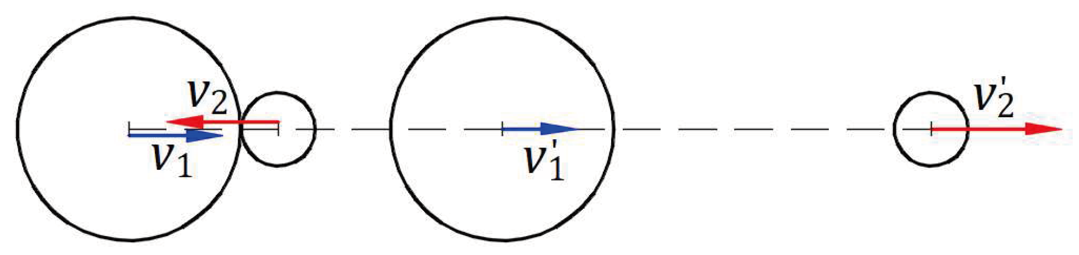
Figure 2.
Elastic reflection of a ball by a moving wall.
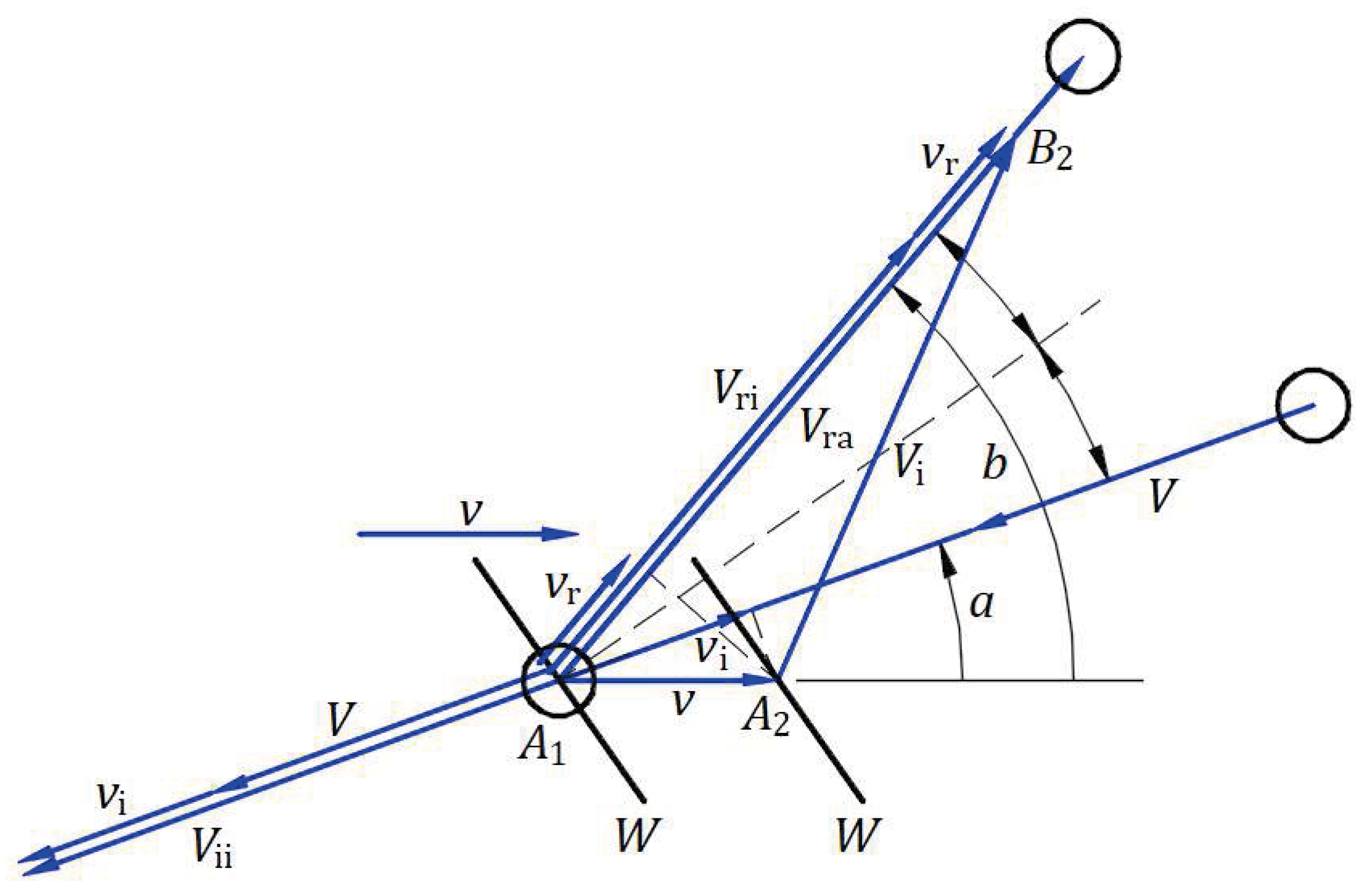
Figure 3.
Emission, propagation, and reflection of balls in the absolute and inertial frames.
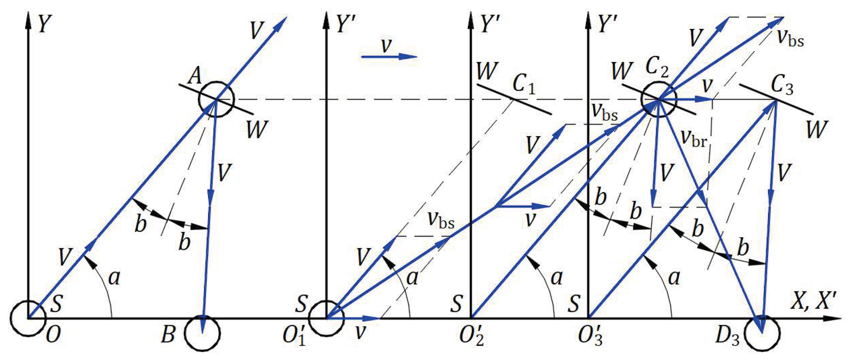
Figure 4.
Reflection of light by a moving mirror.

Figure 5.
Emission, propagation, and reflection of light in the absolute frame and an inertial frame.
Figure 5.
Emission, propagation, and reflection of light in the absolute frame and an inertial frame.
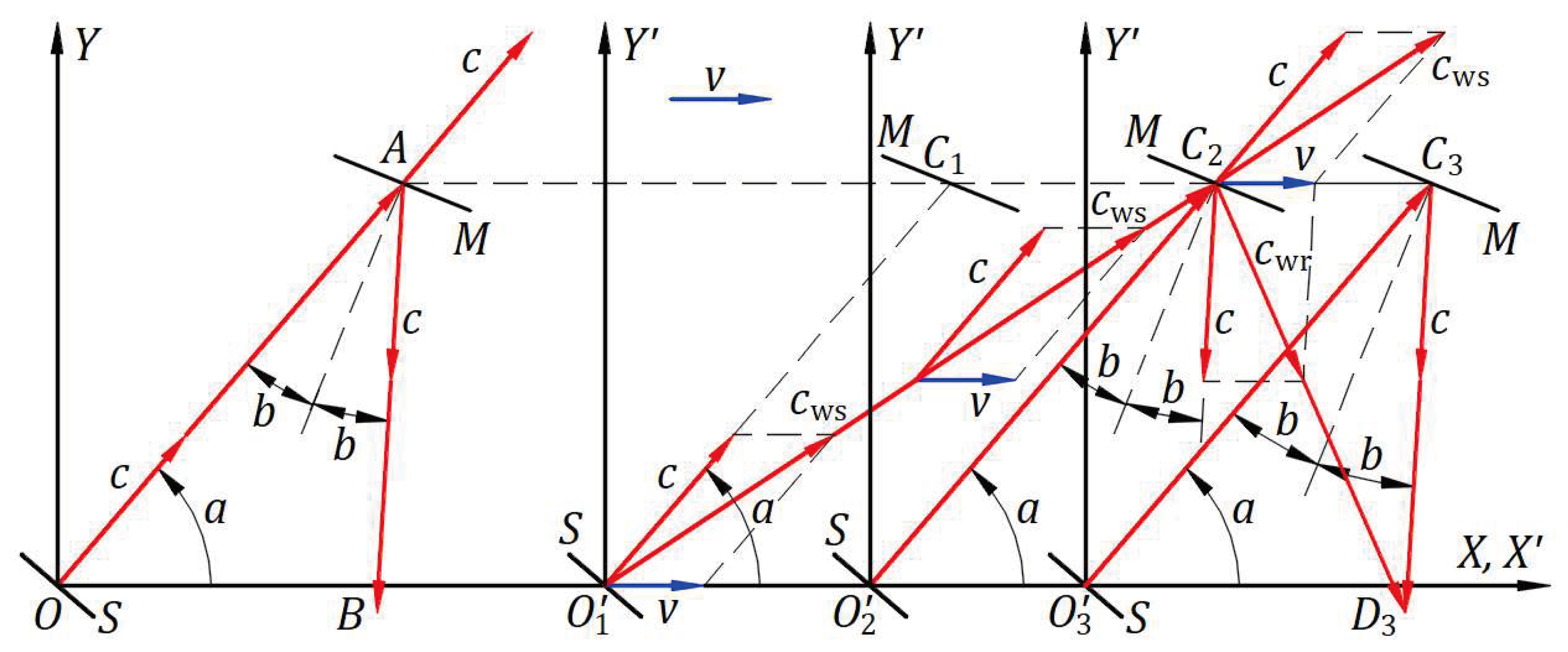
Figure 6.
A boson as a carrier decaying at mechanical speed near the speed of light .
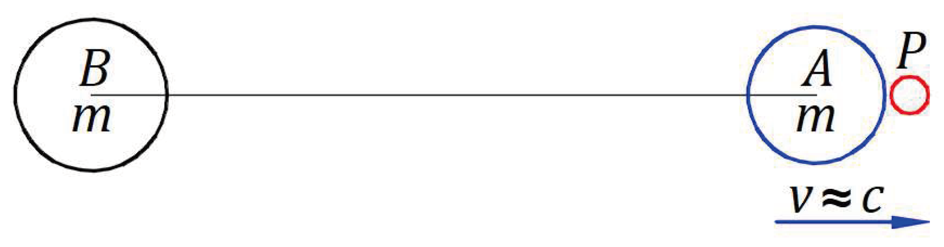
Figure 7.
Observation of a star in the Universe.
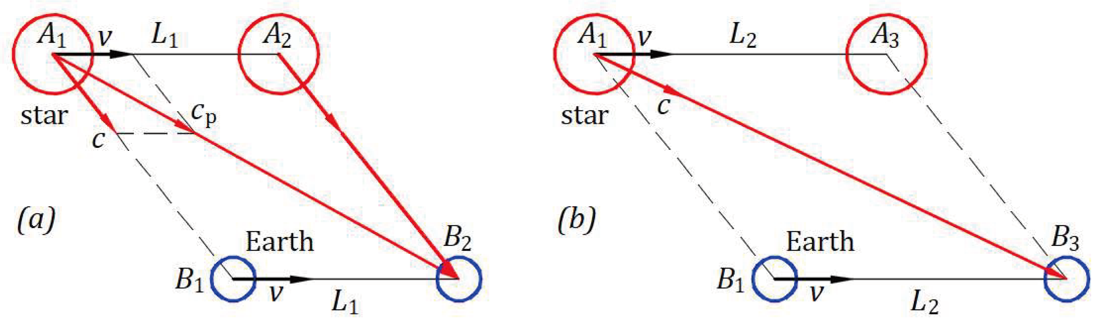
Figure 8.
Observation of a star’s orbit.
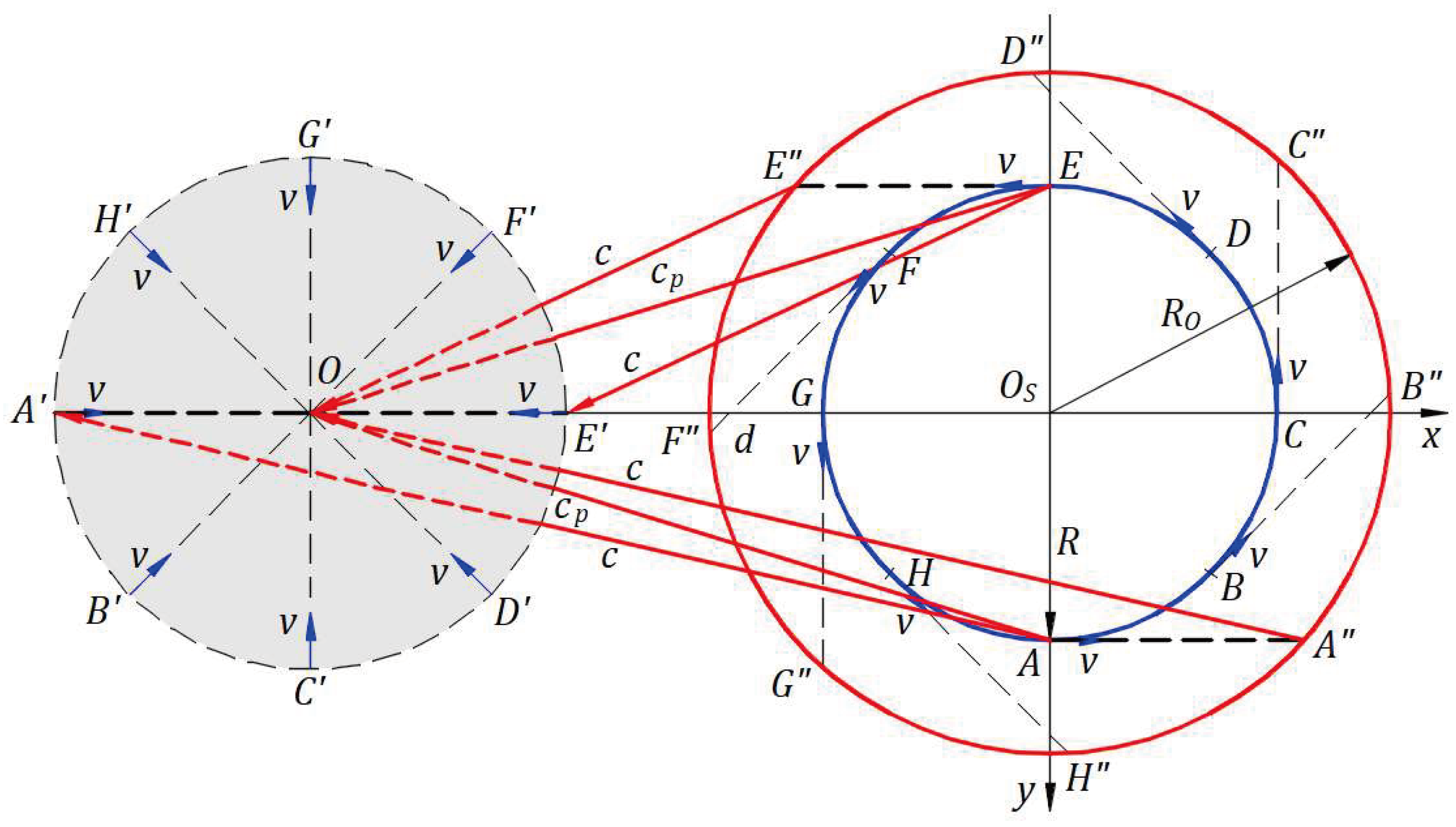
Figure 9.
Galilean coordinates of a spherical light wavefront from a stationary frame shared in an inertial frame.
Figure 9.
Galilean coordinates of a spherical light wavefront from a stationary frame shared in an inertial frame.

Figure 10.
Lorentz’s transformation applied to a circular wavefront of light from a stationary frame to an inertial frame.
Figure 10.
Lorentz’s transformation applied to a circular wavefront of light from a stationary frame to an inertial frame.
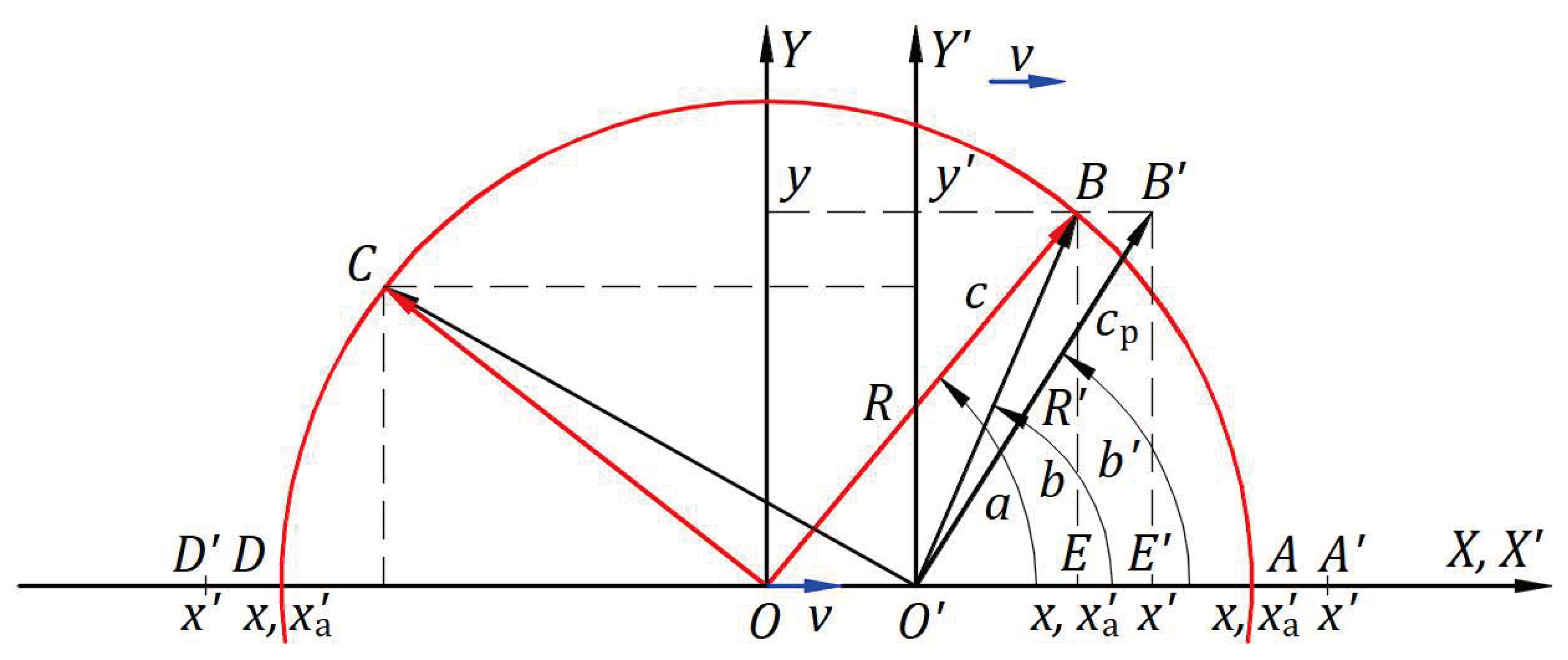

Table 1.
Numerical calculation function of angle for s.
| [°] | ||||
| [m/s] | 2.9997000150E+08 | 2.9997402074E+08 | 2.9998500150E+08 | 3.0000000000E+08 |
| [°] | ||||
| [m/s] | 3.0000000150E+08 | 3.0001500150E+08 | 3.0002598226E+08 | 3.0003000150E+08 |
Disclaimer/Publisher’s Note: The statements, opinions and data contained in all publications are solely those of the individual author(s) and contributor(s) and not of MDPI and/or the editor(s). MDPI and/or the editor(s) disclaim responsibility for any injury to people or property resulting from any ideas, methods, instructions or products referred to in the content. |
© 2024 by the authors. Licensee MDPI, Basel, Switzerland. This article is an open access article distributed under the terms and conditions of the Creative Commons Attribution (CC BY) license (http://creativecommons.org/licenses/by/4.0/).
Copyright: This open access article is published under a Creative Commons CC BY 4.0 license, which permit the free download, distribution, and reuse, provided that the author and preprint are cited in any reuse.


