
Submitted:
30 September 2024
Posted:
03 October 2024
Read the latest preprint version here
Abstract
This study explores the topology optimization technique to design lightweight and compact antennae. The primary objective of this antenna design is to enable its operation across a broad and extensive frequency bandwidth. The optimization process revolves around manipulating the material distribution within the structure. This endeavor successfully yields a novel material distribution characterized by refractive indices spanning the range of 3 to 4. Subsequently, the antenna structure undergoes a binarization process, reducing its constituent features in size, thereby streamlining the fabrication process. The antenna design is accomplished by utilizing the commercial software platform COMSOL Multiphysics, specifically leveraging its optimization module. This scientific approach and methodology contribute to the advancement of metasurface antenna technology.
Keywords:
metasurfaces
; RF antennas
; topology optimization
; digital communication
; electromagnetic field simulation
1. Introduction
The ever-growing demands of wireless communication necessitate compact antennas with a multitude of functionalities: broad bandwidth, proper impedance matching (typically 50 Ohms), specific polarizations (elliptical or circular), minimal interference, and high radiation efficiency [1]. Additionally, cost-effective designs that integrate seamlessly with existing RF components are highly desirable. However, achieving all these goals simultaneously can be challenging due to inherent trade-offs.[2,3] For example, as the operating frequency decreases, the impedance mismatch between a simple dipole antenna and common RF components worsens due to a combination of decreasing radiation resistance and increasing capacitance [4]. Furthermore, the achievable operational bandwidth is inherently limited by the Chu-Harrington limit.[5,6,7,8,9,10] Balancing these conflicting requirements presents a significant challenge in modern antenna design.
Antennas are fundamental components in wireless communication systems, directly impacting factors such as coverage range, signal quality, and overall system performance. Traditional antenna design methodologies often rely on a combination of geometric intuition and trial-and-error approaches. While these methods can be effective, they may not fully explore the entire design space, potentially leading to suboptimal solutions. Topology optimization offers a powerful alternative, providing a systematic framework to explore and optimize both the structure and material distribution of antennas, ultimately resulting in improved performance across various metrics.
This work focuses on topology optimization as a design paradigm for compact, high-performance antennas. Here, we aim to move beyond simply summarizing existing techniques for small antenna design[11].
2. Topology Optimization
Topology optimization is a powerful tool in the engineering design toolbox. It excels at generating innovative and improved layouts for structures. This is achieved by setting an objective function and a set of constraints, which guide the optimization process. The method works by introducing design variables. These variables define how material is distributed within the designated design space, essentially indicating whether material is present or absent at each point. These variables are typically defined on either elements or nodes of a mesh. By manipulating these design variables, the method effectively modifies the structure’s overall topology. This flexibility allows for the creation, removal, and merging of holes within the structure. Additionally, complex, non-standard boundaries can be generated. It’s worth noting that the control parameters used in the optimization process are inherently linked to the chosen method of discretization.
In simpler terms, imagine a designer has a specific goal for a structure (Figure 1(a)), like minimizing weight while maintaining strength. Topology optimization can be used in this scenario. The designer would define this objective and any limitations (constraints) on the design. The software would then introduce design variables throughout the designated design area, like a digital blueprint. By adjusting these variables, the software explores different possibilities for material distribution. It essentially tests various layouts within the constraints, looking for the one that best meets the objective. This process allows for the emergence of innovative and potentially unexpected designs (Figure 1(b)).
The density method defines a control variable field, denoted as , which ranges between 0 and 1. In the context of solid mechanics, a value of indicates the presence of the primary material used for constructing the structure, whereas represents an extremely soft material. Typically, the modulus of elasticity for the void material is set at that of the solid material. For fluid mechanics, the standard is such that is associated with fluid and represents a slightly permeable material, characterized by an inverse permeability factor, . This modification introduces a damping component into the Navier-Stokes equation: [12]
The damping term is set to zero in fluid domains, but a high value is applied in solid domains. This variation effectively approximates the no-slip boundary condition at the interface between the two domains. In simple terms, the topology optimization method involves several key steps. First, a modeling domain that includes a 50 ohm coaxial cable, an infinite perfect electric conductor (PEC) ground plane, and a radiation boundary condition is broken down using the finite element (FE) method. A specific part of this modeling domain is designated as the design domain. The structure of the antenna within this design domain is shaped by how the conductor material is distributed. This distribution is managed by assigning a density to each element, which indicates how much conductor material it contains.
3. Numerical Investigation
To put topology optimization-based inverse design into practice, we designed two types of antennas: a lens antenna and a patch antenna. The lens antenna uses a curved lens to focus radio waves into a straight line, improving signal direction and strength. The patch antenna, on the other hand, consists of a flat metallic patch placed over a dielectric material, which is effective for broadcasting signals over a wide area.
We first constructed models of both antennas in simulation software to refine their designs and optimize performance. For the lens antenna, we aimed to perfect how it channels and directs radio waves. For the patch antenna, our focus was on maximizing the coverage area while maintaining signal strength and quality.
In both cases, we used topology optimization techniques to adjust the distribution and type of materials used in the antennas. This approach helped us minimize signal loss and ensure that each antenna performs efficiently in its intended applications. By optimizing these designs, we aim to create antennas that are not only powerful and efficient but also practical for manufacturing and real-world use.
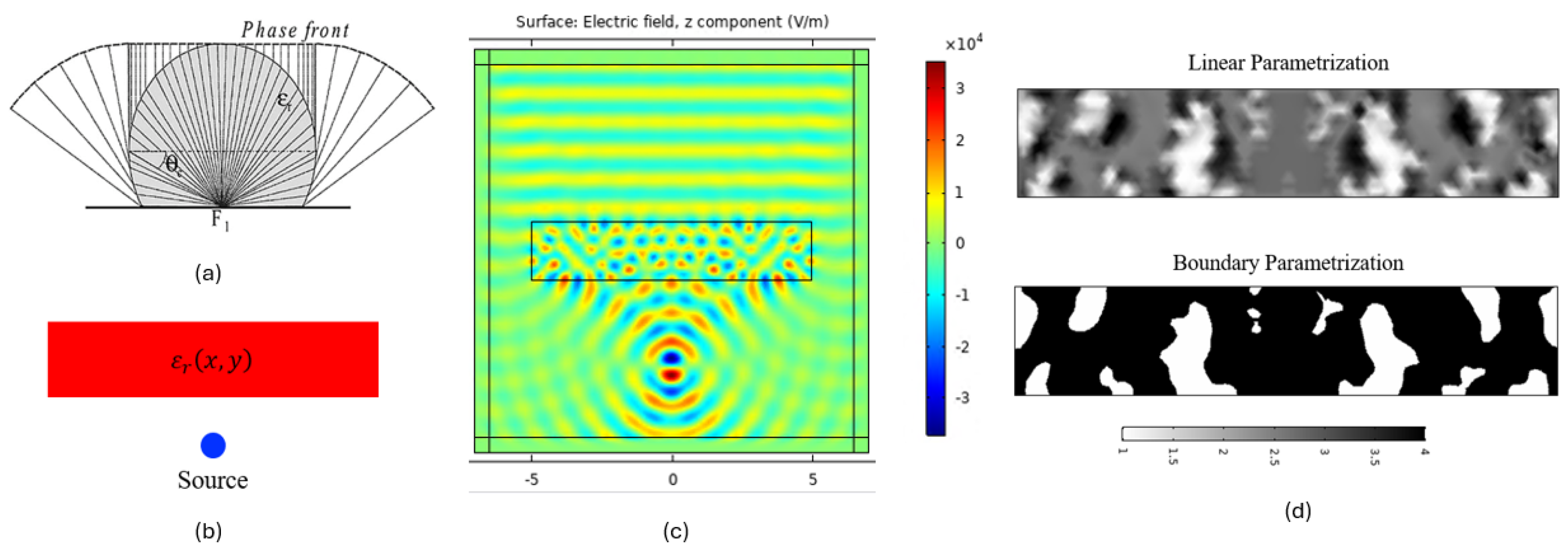
3.1. Inverse-Designed Lens Antenna
We developed a lens antenna using topology inverse-design and refined its structure with topology optimization. This antenna features a spherical lens that turns a spherical wavefront into a linear one (Figure 2(a)). Initially, we designed the antenna as a point source with a specific materials distribution (Figure 2(b)), and then built the structure in COMSOL software(Figure 2(c)). Here, we applied density-based topology optimization to improve the design.
Further, we integrated the design into COMSOL by adding a rectangular metallic patch on a dielectric substrate, employing Periodic Boundary Conditions (PEC).[13] We then focused on optimizing the material distribution within the structure to minimize the s11 parameter, which is crucial for assessing the antenna’s efficiency in terms of reflection loss.
One major challenge with using topology optimization is its reliance on linear parameterization, which can randomize the permittivity and make the structure nearly impossible to fabricate due to its random features. To overcome this, we adjusted the design by binarizing the structure further using boundary parameterization (Figure 2(d)). This step was essential to make the antenna more practical for fabrication while maintaining the desired properties and performance. Through these methods, we aimed to create a highly optimized antenna that meets the demanding specifications of modern applications.
Figure 2.
Inverse-designed Lens antenna. (a) Spherical lens, (b) Model design, (c) COMSOL simulation result, (d) Binarization of the structure
Figure 2.
Inverse-designed Lens antenna. (a) Spherical lens, (b) Model design, (c) COMSOL simulation result, (d) Binarization of the structure
3.2. Inverse-Designed Patch Antenna
To demonstrate the use of topology optimization in antenna design, we designed a microstrip patch antenna using COMSOL 5.4, a commercial software where we defined its geometry. We applied density-based topology optimization to refine the design.
The main goal of our optimization was to improve the s11 parameter, which measures the antenna’s reflection loss and is affected by how the material is distributed within the antenna. We made the geometry half a wavelength () in size to ensure it qualifies as a sub-wavelength antenna, which is essential for achieving better bandwidth and radiation efficiency.
Through this method, we systematically adjusted the material distribution to optimize the antenna’s electromagnetic properties and enhance its performance, meeting the needs of modern RF applications.
3.2.1. Design approach
The geometry of the antenna design was implemented into COMSOL by putting a rectangular metallic patch on a dielectric substrate using Periodic Boundary Conditions (PEC)[13]. The structure was then optimized with respect to the distribution of the material to minimize the s11 using topology optimization.
The feeding mechanism is a very crucial part in a patch antenna design, because it can cause high impedance mismatch if the antenna is fed from edge when connected to a standard 50 ohm transmission line. A common solution involves employing quarter-wave transformer networks between the antenna’s feed point and the 50-ohm line. However, this method has notable disadvantages: firstly, it requires extending microstrip lines beyond the antenna, increasing the overall size of the structure. Secondly, these lines need a higher characteristic impedance, necessitating narrower widths than might be feasible for manufacturing. A more effective approach is therefore sought.
In this study, we explore an alternative feeding method for the patch antenna to enhance the impedance matching with the standard 50-ohm feed. It is established that feeding the antenna from the edge results in higher impedance, whereas a central feed leads to lower impedance. Consequently, there exists an optimal feed point somewhere between the center and the edge of the patch. This matching technique is illustrated in Figure 3. Here, a 50-ohm microstrip line is extended into the antenna structure from one end. The cutout’s width is carefully selected to ensure minimal interaction between the antenna and the line, without substantially altering the antenna’s performance. Additionally, the length of the microstrip line is optimized to reduce reflected power, S11, with the ideal dimensions determined through a parametric analysis.
In the model set on the substrate, specific domains and boundary conditions for electromagnetic waves were defined using a far-field domain tool integrated within the COMSOL to analyze radiation patterns in the E and H planes. The metamaterial incorporated into the geometry features relative permittivity and permeability values of 3.38 F/m and 1 H/m, respectively. These values were derived through the application of the Nicolson-Ross-Weir method[13].
3.2.2. Results
Figure 4(a) illustrates the norm of the electric field within the antenna substrate, presented through an arrow plot where each arrow points towards the direction of dominant polarization aligned with the antenna’s maximum radiation boresight. Additionally, Figure 4(b) depicts the radiation patterns observed in both the E-plane and H-plane. The E-plane correlates with the direction of dominant antenna polarization, while the H-plane represents the plane primarily polarized by the magnetic field.
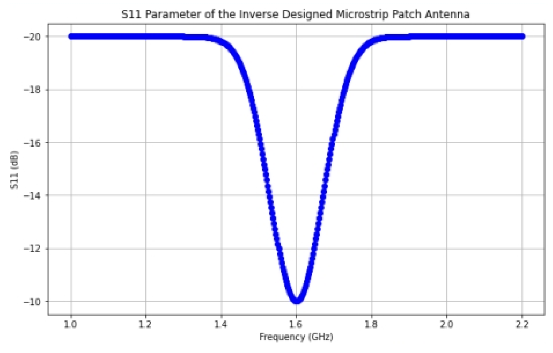
Figure 4(c) displays a 3D far-field radiation pattern, highlighting a directive beam pattern caused by the ground plane which obstructs radiation toward the lower side. The antenna’s directivity is measured to exceed 6.9 dB. Using the selected feed point in this scenario, the S11 parameter shows an improvement beyond -10 dB.
Figure 5 (a) shows the optimized structure after the simulation. This result is obtained using boundary parameterization (Figure 5 (b) ). Linear parameterization (Figure 5 (a) ) will not work because of the random permittivity profile and the device is impractical for fabrication.
The S11 parameter is optimized at the operating frequency of 1.6 GHz (Figure 6), which is a clear indication that we have successfully created an antenna with improved bandwidth.
4. Applications
Topology optimization plays a pivotal role in advancing wireless communication systems by enhancing antenna design. This technique enables the creation of antennas that are not only highly efficient but also tailored to specific frequency bands, space constraints, and environmental conditions. By optimizing the geometry and material distribution, antennas can be made more compact, lightweight, and capable of providing superior signal coverage. In wireless communications, this translates to improved data transmission rates, reduced interference, and extended coverage areas. Whether for mobile devices, satellite communication, or IoT networks, topology optimization empowers engineers to create antennas that are perfectly suited to the demands of modern wireless communication systems.
5. Conclusions
In conclusion, topology optimization has emerged as a very useful tool in the realm of antenna design and applications. This technique has allowed engineers and researchers to push the boundaries of antenna performance and efficiency. By leveraging the power of mathematical algorithms and computational simulations, topology optimization enables the creation of antennas with intricate geometries and material distributions that were previously unattainable. This approach has not only optimized existing antenna designs but has also facilitated the development of entirely new antenna architectures that can adapt to diverse operational requirements. The design discussed in this work can be fabricated at a low cost by a 3D printer which is the next step. Eventually, an array of antennas can be fabricated for wireless communication technology. As we continue to unlock the potential of topology optimization, we anticipate further breakthroughs in antenna technology, enhancing communication systems, radar, and wireless networks, and meeting the ever-growing demands of our interconnected world.
Acknowledgments
This work is overseen by the Center for Metamaterials and the Center for Optoelectronics and Optical Communications at UNC Charlotte. We want to thank Dr. Mario J. Mencagli, who has contributed substantially to designing and original ideas. We also want to thank Prof. Glenn Boreman for guidance in preparing the manuscript.
References
- Sohag, S.H. Low Power-consuming Analog Computing Based on Metamaterials 2022.
- Wheeler, H.A. Fundamental limitations of small antennas. Proceedings of the IRE 1947, 35, 1479–1484. [Google Scholar]
- Mittra, R. Challenges in antenna designs and some novel techniques for meeting them. 2007 Loughborough Antennas and Propagation Conference. IEEE, 2007, pp. 1–4.
- Erentok, A.; Sigmund, O. Topology optimization of sub-wavelength antennas. IEEE transactions on antennas and propagation 2010, 59, 58–69. [Google Scholar]
- Chu, L.J. Physical limitations of omni-directional antennas. Journal of applied physics 1948, 19, 1163–1175. [Google Scholar]
- Collin, R.; Rothschild, S. Evaluation of antenna Q. IEEE Transactions on Antennas and Propagation 1964, 12, 23–27. [Google Scholar]
- Fante, R. Quality factor of general ideal antennas. IEEE Transactions on Antennas and Propagation 1969, 17, 151–155. [Google Scholar]
- Hansen, R.C. Fundamental limitations in antennas. Proceedings of the IEEE 1981, 69, 170–182. [Google Scholar] [CrossRef]
- Fante, R.L. Maximum possible gain for an arbitrary ideal antenna with specified quality factor. IEEE transactions on antennas and propagation 1992, 40, 1586–1588. [Google Scholar]
- McLean, J.S. A re-examination of the fundamental limits on the radiation Q of electrically small antennas. IEEE Transactions on antennas and propagation 1996, 44, 672. [Google Scholar] [CrossRef]
- Fujimoto, K. ; others. Small Antennas; Research Studies Press: London, U.K, 1987. [Google Scholar]
- Doering, C.R.; Gibbon, J.D. Applied analysis of the Navier-Stokes equations; Number 12, Cambridge university press, 1995.
- Nicolson, A.; Ross, G. Measurement of the intrinsic properties of materials by time-domain techniques. IEEE Transactions on instrumentation and measurement 1970, 19, 377–382. [Google Scholar]
Figure 1.
Topology optimization example. Adopted from the examples provided in the Meep simulation software documentation, available at Meep Adjoint Optimization Example: Near to Far Field Transformation (a) Before optimization (b) Optimized structure
Figure 1.
Topology optimization example. Adopted from the examples provided in the Meep simulation software documentation, available at Meep Adjoint Optimization Example: Near to Far Field Transformation (a) Before optimization (b) Optimized structure

Figure 3.
Inverse-designed Patch antenna. S11 paramter is optimized in the design region.
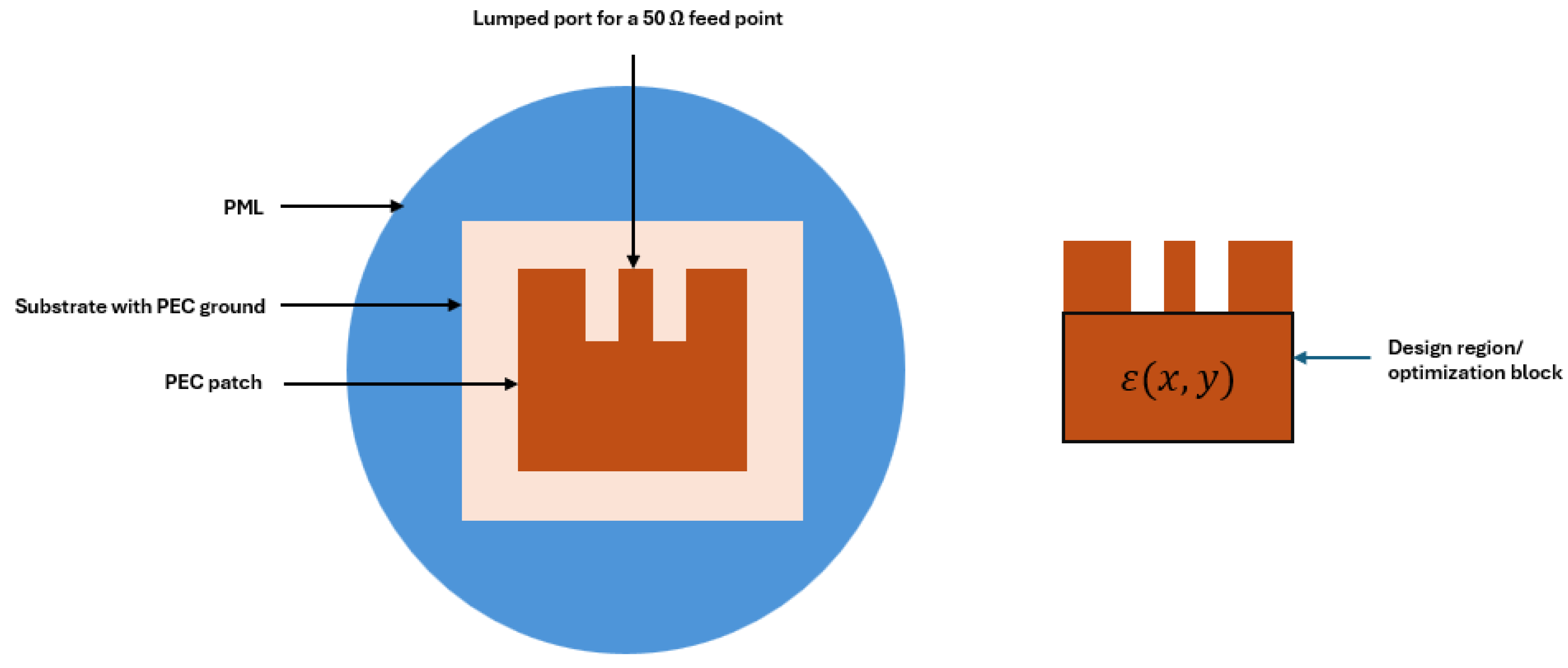
Figure 4.
Inverse-designed patch antenna. (a) E-field norm (V/m), (b) 2D far-field norm, (c) 3D far-field norm
Figure 4.
Inverse-designed patch antenna. (a) E-field norm (V/m), (b) 2D far-field norm, (c) 3D far-field norm
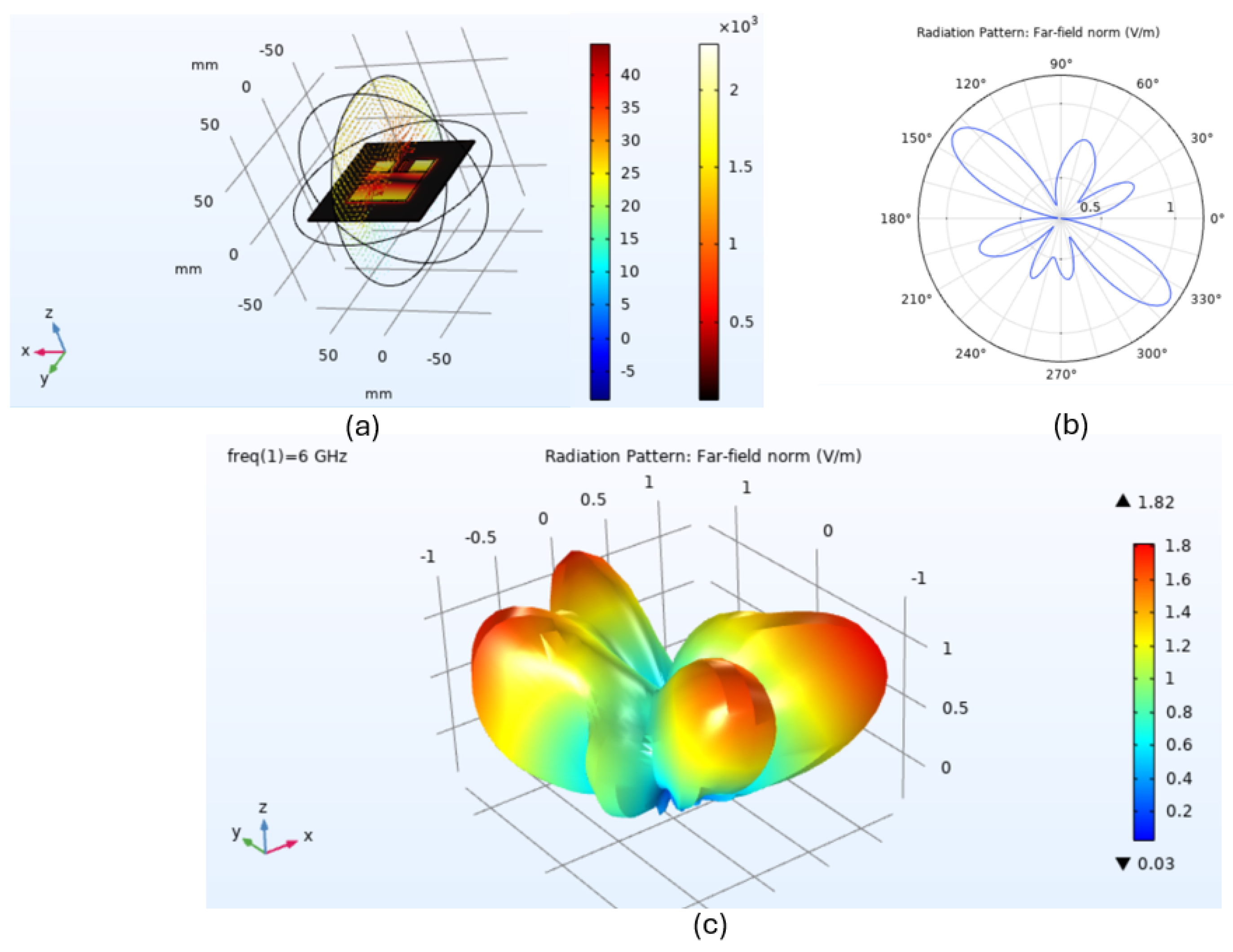
Figure 5.
Inverse-designed patch antenna. (a) Optimized structure, (b) grayscale permittivity profile, (c) Binarized permittivity profile
Figure 5.
Inverse-designed patch antenna. (a) Optimized structure, (b) grayscale permittivity profile, (c) Binarized permittivity profile
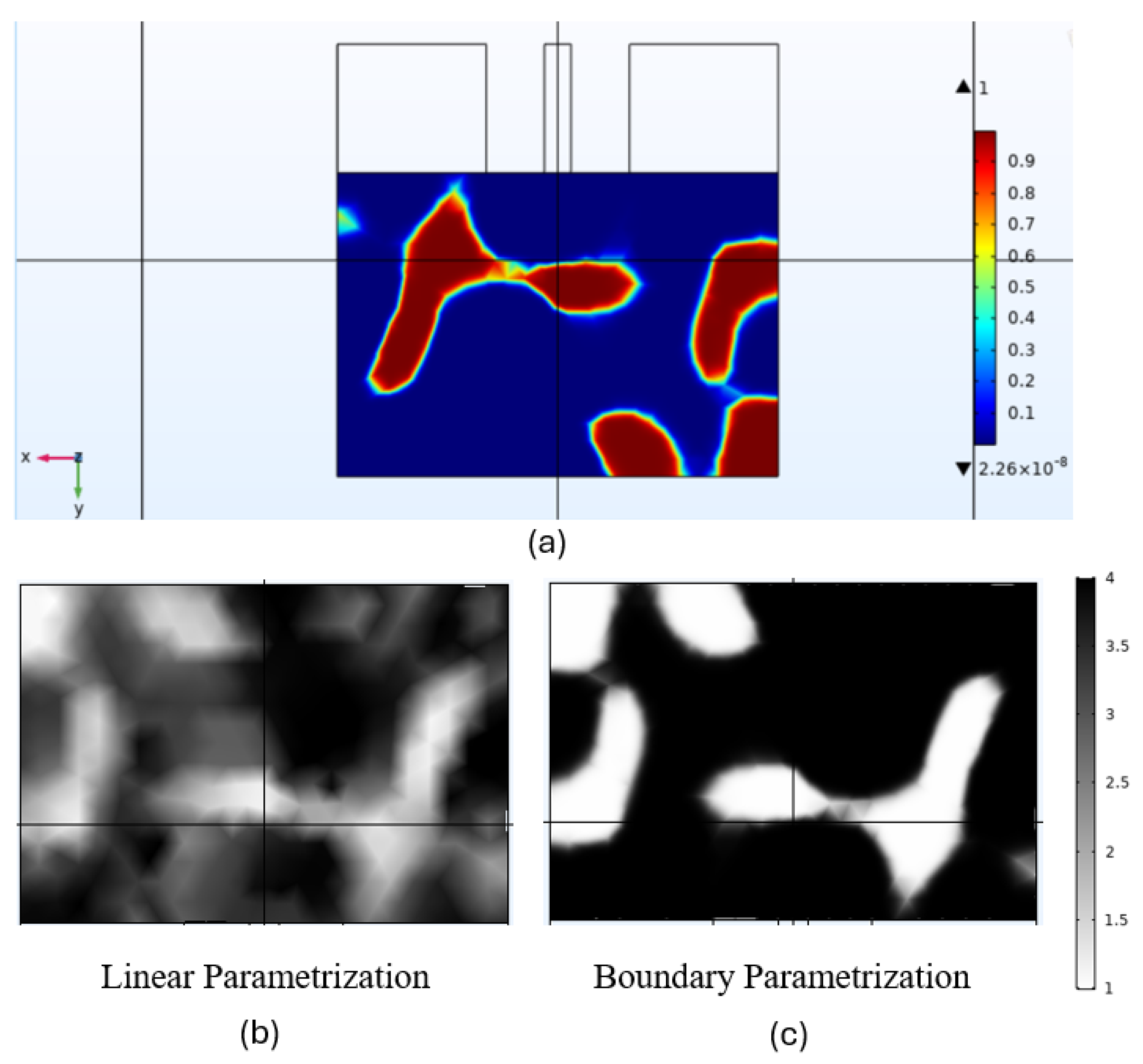
Figure 6.
Inverse-designed patch antenna. S11 parameter
Disclaimer/Publisher’s Note: The statements, opinions and data contained in all publications are solely those of the individual author(s) and contributor(s) and not of MDPI and/or the editor(s). MDPI and/or the editor(s) disclaim responsibility for any injury to people or property resulting from any ideas, methods, instructions or products referred to in the content. |
© 1996 by the authors. Licensee MDPI, Basel, Switzerland. This article is an open access article distributed under the terms and conditions of the Creative Commons Attribution (CC BY) license (https://creativecommons.org/licenses/by/4.0/).
Copyright: This open access article is published under a Creative Commons CC BY 4.0 license, which permit the free download, distribution, and reuse, provided that the author and preprint are cited in any reuse.


