Submitted:
06 January 2025
Posted:
07 January 2025
You are already at the latest version
Abstract
We propose a durable and easy-to-operate treatment, modified epoxy composite coating (MECC)., as a potential alternative to traditional epoxy resin protectants to enhance the protection of concrete structures. This new material consists of epoxy resin as the base material, dimethyl carbonate as the solvent, and modified amines + polyaniline as a composite curing agent that reacts with epoxy resin to form a film over the surface of concrete, thus protecting concrete structures from surface cracking, peeling and spalling when exposed to chloride. Salt frost resistance test indicated that the MECC specimens had lower water absorption and much higher salt frost resistance. Compared with the non-coating (NS) specimens, after 200 freeze-thaw cycles, the relative dynamic elastic modulus (RDEM) was 21.62% higher and the mass loss was merely 19.14% of that of the NS specimens. Better performance was achieved as compared with ordinary epoxy resin coating (EC) and silicate coating (SC), too. After 120 days of erosion in 10.0% NaCl, the coating could effectively prevent environmental liquids and chloride from intruding through the cracks. The reason behind the increased salt frost durability is that treatment with MECC improved the internal structure of concrete and made its surface dense enough to prevent the intrusion of environmental liquids and chloride. Under repeated freezing and thawing, the degree of chloride-induced damage and the icing pressure inside the concrete were greatly reduced. This relieved the frost damage inside the concrete and elongated the service life of concrete.
Keywords:
Cement concrete
; Surface coating
; Modified epoxy composite
; Salt frost resistance
; Microscopic mechanism
1. Introduction
Chloride erosion into concrete, as a highly hazardous aggressive media damage and one of the major factors compromising the durability of concrete, is reported to cause enormous economic losses every year [1]. For concrete structures on highways and bridges, surface coating is the most common way of protection, especially in cold areas. Coating protection can minimize physical and chemical erosion damages to concrete structures caused by snow melting agents and deicing salts and prevent them from deteriorating prematurely due to durability problems [2,3].
For economic considerations, the deicing salts for highways and bridges are primarily composed of chloride, whereas the erosion of chloride solutions constitutes one of the main contributors to damages on highways and bridges. Chloride ions are detrimental to concrete structures on highways and bridges in two ways [4]. On the one hand, they crystallize into salt inside cement concrete and expand, causing cement concrete to crack. Chloride ions displace with the calcium hydroxide in cement. Due to the presence of Chloride ions, the CaCl2 generated is more soluble than Ca (OH)2. That is, the osmotic pressure of salt solution causes the water inside the concrete to migrate toward the external surface, causing the concrete to expand and crack more rapidly. When the concentration of CaCl2 in the concrete is high (>15%), it can combine with CaO into very tiny, needle-like crystals in the liquid phase which, when sufficiently accumulated, can lead to expansion and corrosion of the concrete [5]. Microscopic studies have also demonstrated that Chloride ions can penetrate into concrete and damage the internal structure of gel; presence of high-concentration chloride can intensify the dry shrinkage of concrete [6,7]. On the other hand, the use of snow melting agents and deicing salts cause an increase in the Chloride concentration on the surface of highways and bridges. With small radius and high activity, chloride ions can easily penetrate the passivation film of the concrete and cause the reinforcement to rust [8]. When the chloride content in the solution is high or after repeated dry/welt cycles, more salt will be brought into the concrete. As a result, crystallized salt will produce high crystallization pressure in the concrete pores and cause the concrete surface to spall, crack or crumble, resulting in a shorter service life of the concrete structure than expected by design [9,10].
In order to increase the service life of concrete structures, research has been made around green, low carbon and coating protections of concrete materials [12,14]. The purpose is to obtain better concrete performance, especially surface protection and maintenance, [15]. Epoxy coatings comprising primarily of epoxy resin have been developed and widely applied [16]. The idea behind this treatment is to form a tight physical protection over the concrete surface [2], so as to prevent aggressive media from coming into the interior of the concrete and increase its durability [3,4]. Today, epoxy resin coatings are still the most widely used, most widely applicable and the most important corrosion protection in the world. Surface coating can form a dense watertight layer over the concrete surface and prevent external corrosive media from intrusion. Diamanti et al. [17] investigated the effect of polymer-modified cementitious coatings of two different polymer-to-cement ratios on the water permeability of concrete and found that epoxy resin coatings as a physical barrier is well able to minimize water intrusion into concrete. Unfortunately, the durability of epoxy resin-cured materials is heavily restricted by their high internal stress, low toughness, ready degradation under high temperature, and poor wet stability [3,12,17]. To solve these problems, Fei Li [16] prepared a water-based hydrophobic slurry by combining two cost effective, highly available materials, epoxy resin and octadecylamine (ODA), and used it as a binder in o-concrete. They eventually created a superhydrophobic concrete composite (SCC) with a water contact angle of 156° and sliding angle of 8°. Liu [17] prepared a nano-composite anti-corrosion filler with a mass ratio of CeO2: GO = 4:1 by hydrothermally growing cerium oxide on the surface of graphene oxide. The corrosion resistance of reinforced concrete in the marine environment was effectively improved. Guo et al. [17] prepared a novel TiO2-graphene modified epoxy resin as a coating for ordinary Portland cement (OPC) concrete. It was found that adding given amounts of TiO2-graphene nanofiller (0.3 % and 0.5 %) greatly improved the impermeability of chloride (as reflected by capillary adsorption and chloride permeability). Silicone, which features Si-O bonds with high bonding energy [20], has been proved to improve the thermal stability, weather resistance, and brittleness of epoxy resin [21,22]. Also, as silicone has low surface free energy, when applied over the surface of epoxy resin, it can enhance the water and oil resistance of the material [23]. Zheng et al. [24] prepared a solvent-free, epoxy heavy-duty anticorrosive coating composed of modified epoxy resin, reactive toughening diluent, and other additives and significantly enhanced the material’s resistance to salt spray and corrosion. Qu et al [23] prepared coated concrete specimens by addingnano-SiO2 and nano-TiO2 into epoxy resin coating and subjected them to accelerated aging under ultraviolet irradiation, followed by accelerated carbonation or Coulomb electric flux test. The long-term carbonation and chloride erosion resistance of the coated concrete were significantly improved. Fernández-Álvarez et al. [26] discovered that SiO2 nanoparticles can increase the contact angle of cryptic epoxy resin coatings and enhance their resistance to permeation and chloride ion erosion. So far, research has covered many types of anticorrosive coatings, including solvent-based and solvent-free epoxy anticorrosive coatings [3,27]. Dorado et al [26] demonstrated that the most promising adhesion values can be delivered by adding 3 wt% of the synthesized Fe2O3 nanoparticles into a graphite carbonaceous matrix; the nano-modified coating displayed much greater resistance to chemical corrosion and surface wear. However, there are some problems pending further studies, such as the cost of nanoparticles and silicone as a modifier, and the weather resistance of rubber-modified epoxy resin [2,3,15].
Engineering practices in northern China have proved that epoxy resin coatings for highway and bridge concrete structures lack sufficient freeze-thaw durability [29], since aggressive media like hydroxide and Chloride solutions will penetrate through the coating and react with concrete, resulting in gradual failure of the physical protection [5,6]. Within the second to third service year of the epoxy resin coating, surface spalling and structural strength degradation will occur to the structure as a result of freezing and thawing processes involving chloride [30,31]. This greatly shortens the maintenance cycle and increases the maintenance workload, bringing additional labor and material costs [32,33]. It is therefore very necessary to improve epoxy resin products and make the concrete coating more durable, especially in seasonally frozen areas where highway concrete structures are exposed to erosion induced by snow melting agents.
In the present study, we present a modified epoxy resin coating material and an improved epoxy resin protectant to provide longer surface protection for and enhance the durability of concrete structures on highways and bridges. Considering that dimethyl carbonate is safe and environmentally friendly and polyurethane has excellent weather and chemical resistance, high gloss, and good wear stability, we used dimethyl carbonate as the solvent and modified amines + polyaniline as a composite curing agent that reacts with epoxy resin to form a film. Through laboratory freeze-thaw tests, we determined the mass loss and relative dynamic elastic modulus (RDEM) of cement concrete specimens in 3.50 wt% NaCl and water, as well as their Chloride ion permeation resistance and saturated water absorption. We then measured the pore structure parameters of the specimens by mercury intrusion porosimetry (MIP) and industrial computed tomography (CT) and analyzed the mechanism underlying the salt frost durability of the MECC specimens from the micropores perspective.
2. Materials and Methods
2.1. Materials
Table 1 gives the chemical composition of the cement. The fine aggregate consisted of natural river sand (with fineness modulus = 2.7 and bulk density = 2710 kg/m3). The coarse aggregate was 5–10 mm and 10–20 mm continuously graded. Table 2 gives the mixing ratio of the cement concrete specimens. The concrete had a water-to-cement ratio of 0.46 and a 28-day compressive strength of 46.0 MPa. The cement was P.O.42.5 Portland cement produced by Hangzhou Haishi Cement Co., Ltd (with specific area = 300 m2/kg and consistency = 22.5%). The water reducer was high-efficiency polycarboxylate water reducer produced by Shanxi Transportation Research Institute Group Co., Ltd. The test water was tap-water. Three concrete surface modifiers were used, including silane, ordinary epoxy resin and the modified epoxy resin, as provided by Shanxi Transportation Research Institute Group Co., Ltd. Modified composite part A was prepared in the mixing ratio of epoxy: mica: glass flake: mica iron oxide: promoting agent: zinc phosphate: penetrant:solvent =100:15:20:10: 10: 5:3: 10, using dimethyl carbonate as the solvent, in which the layer structure of mica and sheet structure of mica iron oxide form the excellent barrier properties of MECC, capable of preventing the dispersing of corrosive medium (Cl-/SO42-). By using the function-similar glass flake, it can provide an aid to form complicated and flexural penetrating and dispersing pathway inside the MECC, by which the matrix is difficult to be corroded owing to flexural dispersing pathway of corrosive medium. The zinc phosphate can facilitate the formation of compact and indissolvable protective film in MECC, in addition, the chemical antirust effect is also available. The promoting agent and penetrant play a main role of assisting modified epoxy resin to be penetrated deeper in the surface structure so that may form a more compact coating. Modified composite part B was prepared in the mixing ratio of heterogeneous polyaniline: N-methylpyrrolidone (NMP): modified amine curing agent = 20: 100: 30. Part A and Part B were mixed in the mixing ratio of A:B = (2.5–3.5): 1 to produce the desired modified composite epoxy resin material for concrete surface. The epoxy resin anticorrosive material was a film-forming transparent emulsion with effective content of 81.0% and coating thickness of 2.8–4.0 mm. The silane was a silane-impregnated penetration coating composed mainly of high purity isobutyl silane with silane content of 98.9%. The chloride solution for preparing the environmental solution consisted of sodium chloride powder (AR, 99%), produced by Shanghai Aladdin Biochemical Technology Co., LTD.
2.2. Sample Treatment
The concrete specimens were treated with three different types of coating and then tested. Table 3 gives the treatment procedures for different types of coating. The cement concrete specimens were demolded 24 h after they were formed and then cured in the curing room at the temperature of 20±3℃ and relative humidity of 90±3%. After they were cured for the given days, the specimens were surface finished in the way respectively recommended for the different types of coating and the results were compared. Before the coating specimens were tested, they should be cured at the temperature of 25℃ and relative humidity of 65%.
2.3. Experimental Design
2.3.1. Salt Frost Resistance Test
In addition to following the “Standard for test methods of long-term performance and durability of ordinary concrete” (GB/T50082-2009) [34], we applied a new test procedure and tested the cement concrete specimens by erosion and freezing and thawing, as shown in Figure 1. First, we surface finished the 100 mm × 100 mm × 400 mm specimens and then eroded them in 10.0 wt% NaCl solution for 120 days. Then, we took the specimens out, tested their initial ultrasonic velocity and then subjected them to rapid freezing and thawing for 200 cycles in 3.5 wt% NaCl solution according to the main snow melting agent type for highway projects [9,29]. The rapid freeze-thaw test was conducted at the maximum and minimum temperatures of 5℃±2℃ and -18℃±2℃ and the duration of 4 h for each cycle. After every 25 cycles, we tested the mass loss of the specimen. After every 40 cycles, we tested the RDEM ultrasonically and replaced the solution in the test tank. After finishing all freeze-thaw cycles, we measured the residual compressive strength of all specimens
2.3.2. Water Absorption
Impermeability is associated with environmental erosion resistance. The water absorption of the cement concrete specimens (150 mm × 150 mm × 150 mm) was measured according to the “Standard for test methods of concrete physical and mechanical properties” (GB-T 50081-2019) [35]. The specimen to be tested was completely immersed in water, with the top surface of water 5.0±0.5 mm above the top surface of the specimen. First, we measured the surface dry mass of the specimen (ms). Each specimen was immersed in water for a minimum of 48 h and until and the mass change over two 24 h intervals was less than 0.2% of the larger value. After measurement, we dried the specimen in a 105±5℃ drying oven and then measured the mass of the dried specimen (md). Each specimen was dried for a minimum of 48 h and until the mass change over two continuous 24 h intervals was less than 0.2% of the smaller value. The concrete water absorption Wr was calculated by Eq. (1):
2.3.3. Rapid Chloride Permeability Test
We tested the permeability of Chloride ions in the coating specimens by rapid chloride permeability test (RCPT) [34] and observed the surface morphology of the specimens after 120 d long-term immersion. RCPT specimens sized φ100 mm × 50 mm, immersed in 10.0 wt% NaCl solution). We used a YC-RCM concrete chloride ion migration coefficient tester for this purpose. While the test system was energized, the solutions in the vessels at the sides of the system were 0.3 mol/L NaOH (positive pole) and 3.0 wt% NaCl (negative pole). Under an applied electric field of 60 V, we measured the current flowing through the specimen every 30 min. The test lasted 6 h. We then calculated the total electric flux of the specimen according to Eq. (2), where Qs(C) denotes the electric flux through the φ95 mm×50 mm concrete specimens and Qx(C) denotes the electric flux through the φ100 mm × 50 mm concrete specimens. Table 4 gives the RCPT evaluation criteria for chloride ion permeability.
2.3.4. Microstructure Testing
We examined the pore distribution and permeability variation of surface samples by MIP, using a Micromeritics AutoPore V 9620 analyzer. The samples were concrete surface cubes sized 10 mm×10 mm × 10 mm. We then investigated the freeze-thaw damage of the concrete internal structure by CT, using an EcoVision Y. CT Precision high-accuracy CT system. The samples were concrete internal cubes sized 40 mm × 40 mm × 40 mm, taken from the same freeze-thaw damaged samples with a cutting machine.
3. Results
3.1. Salt Frost Resistance
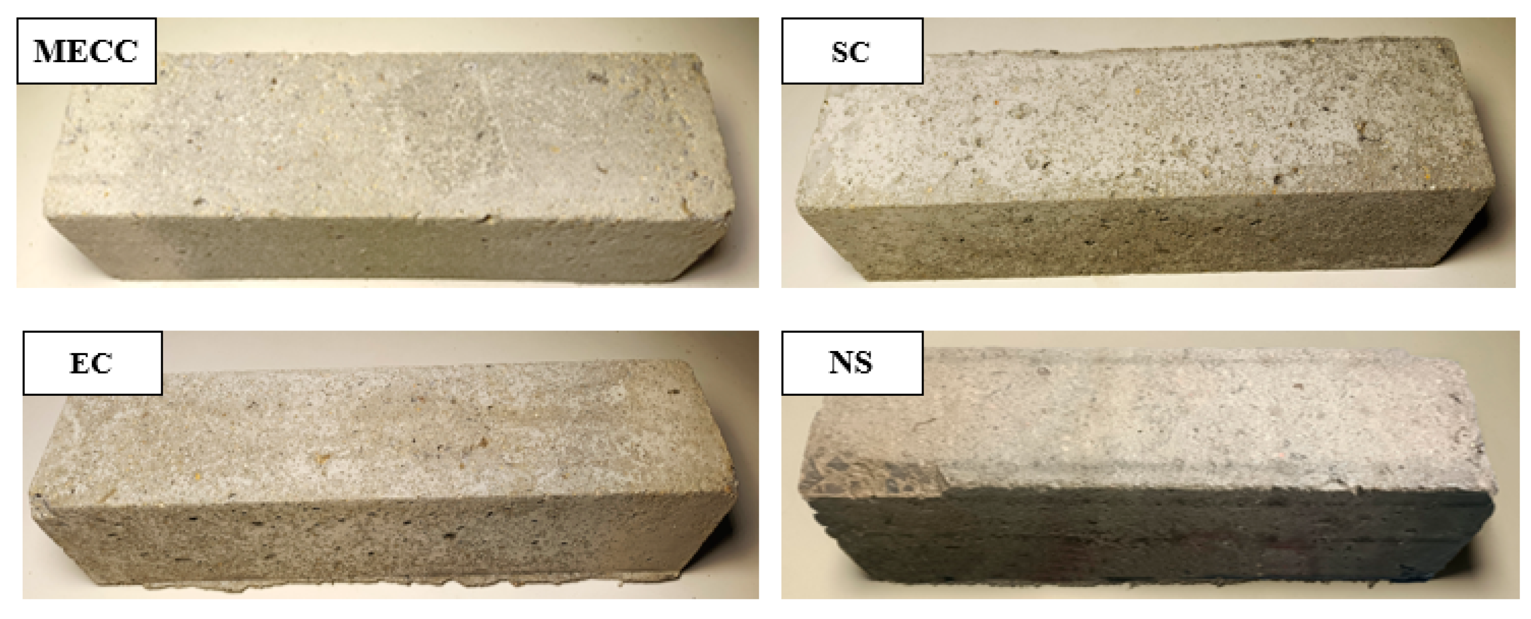
To investigate how MECC performs on the salt frost resistance of concrete, we analyzed the frost performance of concrete specimens in terms of RDEM, mass loss, and residual compressive strength [36]. Figure 2 and Figure 3 compare the mass loss and RDEM of different specimens under different numbers of freeze-thaw cycles. Figure 4 and Figure 5 compare the residual compressive strength and surface morphology of the specimens after 200 freeze-thaw cycles. Overall, MECC could enhance the salt frost resistance of concrete structures and was better able to enhance the salt frost durability of concrete structures than ordinary epoxy resin and silane. Under the same freeze-thaw cycles, the MECC specimens had the lowest mass loss and RDEM loss and the highest residual compressive strength, meaning that it had the least freeze-thaw damage. From the surface morphology, the NS specimens had the worst surface damage. All coarse aggregate inside the concrete at the corners was exposed. On the surface of the SC and EC specimens, there are quite many holes, although fewer holes are observed in the EC specimens. Both groups show slight slagging on the surface, but no aggregate spalling or damage is detected. The MECC specimens maintained good surface morphology and fairly uniform surface color, with limited pore exposure and no aggregate spalling.
The NS specimens ranked the worst for all three evaluation criteria, with the largest average mass loss (256 g). None of the coating specimens suffered aggregate spalling except some surface damage for the SC and EC specimens. The surface morphology of the MECC specimens was well intact. The average mass losses of the coating specimens were 99 g (SC), 71 g (EC), and 49 g (MECC), which were 38.67%, 27.73%, and 19.14% of that of the NS group. Throughout the freeze-thaw test, the surface damage of the NS specimens intensified after 50 freeze-thaw cycles and their mass loss became obvious. For the coating specimens, as they were protected with surface coating, mass loss took place more mildly and slowly. In fact, mass loss did not intensify significantly for the SC and EC groups until after 150 cycles; the mass loss rate of the MECC group remained almost unchanged throughout the test, suggesting that MECC is a reliable surface protection for concrete structures.
We analyzed the RDEM variations of the specimens. After 200 freeze-thaw cycles, the RDEM values of the four groups of specimens were 67.89% (NS), 85.24% (SC), 87.06% (EC), and 89.51% (MECC). Surface coating increased RDEM by 17.35%, 19.17%, and 21.62%. NS also showed the largest RDEM loss among all groups, followed by SC, EC and MECC, which was consistent with what has been observed for mass loss. Silane can improve the salt frost performance of concrete, but SC did not perform as well as EC or MECC in the next half of the freeze-thaw test. The EC group showed roughly the same surface damage as the SC group and its RDEM loss further reduced, too. Notably, color unevenness can be observed on the surface of the EC and SC specimens, possibly because the surface coating on these two groups of specimens was not uniformly distributed on the concrete substrate. Under freeze-thaw cycling, the protection in some areas disappeared, leading to premature damage to the concrete surface there. Even though the damaged areas are not at the corners, erosion of these areas could result in local damage while leaving the other areas intact. However, further studies will have to be made to confirm this possibility. Compared with the other three groups, after 200 rapid freeze-thaw cycles, the RDEM loss of the MECC group reduced by 21.62% (NS), 4.27% (SC), and 2.45% (EC), and the specimens had a longer MECC decay cycle. According to the specified criteria for frost resistance, this signifies that the MECC group can withstand more freeze-thaw cycles before reaching the same damage limit. In other words, they have better frost durability.
Residual compressive strength is another important criterion for evaluating the degree of internal damage of concrete specimens [36,37]. From Figure 4, the residual compressive strength of the NS specimens was 29.03 MPa, which was about 63.10% of the initial level. For the SC, EC, and MECC specimens, the residual compressive strengths were 32.86 MPa, 34.79 MPa, and 36.08 MPa, which were 13.21%, 19.85%, and 24.28% higher than that of the NS specimens. This indicates that surface coating can effectively enhance the frost resistance of concrete. Overall, the MECC specimens had the best frost resistance, which is inspiring for the research and development of this new type of surface treatment.
Figure 5.
Surface morphology of concrete specimens after 200 freeze-thaw cycles in 3.5 wt% NaCl solution.
Figure 5.
Surface morphology of concrete specimens after 200 freeze-thaw cycles in 3.5 wt% NaCl solution.
3.2. Water Absorption
As a physical barrier for protecting cement concrete, one of the roles of coating is to largely reduce water intrusion into the interior of concrete and reduce the icing pressure there, consequently the freeze-thaw damage under repeated freezing and thawing [3,8,38]. Water absorption test is to detect how different types of coating prevent water intrusion into the interior of concrete. Figure 6 compares the water absorption test results of different specimens. When the specimens were immersed in water, the water absorption of the NS specimens increased steeply over the first 48 h. As the immersion time further increased, they slowed down water absorption and became saturated at 2.16%. For the coating samples, the water absorption was much lower, as previous expected, being 1.32% (SC), 1.13% (EC), and 0.93% (MECC). The MECC specimens had the lowest water absorption, which was 56.94% lower compared with the NC specimens. The EC specimens showed roughly the same water absorption increase as the MECC specimens: they absorbed water at a slowly increasing rate over the first 36 h and were nearly saturated when immersed for more than 48 h. Notably, the water absorption of the SC specimens was still rising even after 72 h, which also concurs with existing studies which assumed that silane cannot prevent external solutions from intrusion when oversaturated. Furthermore, as environmental solutions are the vehicle for aggressive ions, such as chloride ions, from coming into the interior of concrete, low water absorption can also result in a reduction in total chloride ion intrusion and reduce the freeze-thaw damage induced by chloride [39], as will be proved in Section 3.3 below.
3.3. Chloride Ion Penetration Resistance
In this section, we prove that coating can enhance the chloride ion erosion resistance of concrete by means of fully submerged visual observation and RCPT test. Figure 7 shows the surface morphology of the four groups of specimens after 120 d erosion in 10.0 wt% NaCl solution. Visible cracks appeared on the surface of the NS specimen, with visible spalling and aggregate exposure at the corners. No visible erosion can be observed on the surface of any of the coating specimens except for some slight slagging at the corners, which was mostly caused by the molding and repeated handling of the specimens. Spalling of the concrete surface and the resultant production of a large number of cracks will lead to an increase in the intrusion of environmental liquids and corrosive ions, adding to the internal damage of the concrete structure under freezing and thawing [30,40]. Hence, from an engineering point of view, the EC and MECC specimens are closer to ideal in terms of surface morphology.
Table 5 gives the RCPT results of the four groups of concrete specimens. The average electric flux of the NS specimens was 2128, rated as “medium”. The average electric fluxes of the coating groups were much lower, being 283 (EC), 367 (SC), and 157 (MEEC), which were 13.33%, 17.28%, and 7.39% of that of the NS group. Their ratings were all “very low”. The concrete permeability increased by 2 grades, suggesting that the three types of coating worked effectively to enhance the chloride ion erosion resistance of concrete. Furthermore, the RCPT results are in good agreement with the water absorption results. The transmission channels inside the MECC specimens were more effectively blocked. The SC group performed the worst among the three coating groups. When oversaturated, SC coating did not act effectively in preventing external water from intrusion [2,3].
3.4. Porosity and Pore Size Distribution
We tested the pore structure distribution on the surface of the concrete specimens by means of MIP test. After the freeze-thaw test, we took out the specimen and cut it to the desired size. Figure 8 compares the pore structure of the specimens. The total porosities of the NS, SC, EC, and MECC specimens were 15.98%, 14.04%, 12.63%, and 11.54%. The lower overall porosity of the coating specimens compared with the NS specimens was attributed to the physical barrier provided by the three protectants. However, in terms of pore type, MECC improved the pore structure of cement concrete more remarkably. Concrete pores are categorized into harmless, low harm, harmful, and high-harm pores. The pore sizes include < 20 nm, 20–50 nm, 50–200 nm, and >200 nm [41], as shown in Table 6. Two positive changes can be detected in the internal pore distribution of the MECC specimens. Firstly, the number of >50 nm harmful pores and the proportion of harmful pores reduced. Compared with the NS, EC, and SC specimens, the number of harmful pores (>50 nm) in the MECC specimens was 31.69%, 34.47%, and 48.02% smaller. Secondly, the proportion of 20–50 nm low-harm pores was larger. Compared with the NS, EC, and SC specimens, the number of < 50 nm low-harm pores in the MECC specimens was 29.25%, 35.37%, and 28.60% larger. This indicates that under the same freeze-thaw cycles, MECC greatly prevented the deterioration of the concrete microstructure, reduced total porosity level, increased the number of harmless and low-harm pores that benefit frost resistance and relieved the damage to the surface structure [39,40,41]. If further frost resistance experiments were performed, the MECC specimens would prove to have a longer freeze-thaw life than the other groups. For the EC and SC specimens, except a smaller proportion of high-harm pores (>200 nm), the pore distribution is similar to that of the NS specimens, which concurs with the test results descried in Section 3.1. After 200 freeze-thaw cycles, the physical barrier of the SC and EC specimens was nearly consumed and their microstructure was deteriorated, leaving unevenly distributed pores and cracks on the surface. For the MECC group, as the internal structure was denser, under the same freezing and thawing conditions, the physical protection did not disappear completely. Hence in terms of surface morphology, only part of the MECC specimens was locally damaged by erosion and the other areas remained intact. However, further studies will have to be made to confirm this possibility.
We further determined the internal damage of the coating specimens and NS specimens by CT. Figure 9 compares the three-dimensional reconstruction images of the internal structure of the specimens. Table 7 gives the pore structure characteristics. After 120 d salt erosion and 200 freeze-thaw cycles, the total porosities of the internal structures of the NS, SC, EC, and MECC specimens were 4.60%, 4.01%, 3.32%, and 3.00%. The overall density of the internal structure can be directly observed in the images. Consistent with the MIP test results, the coating groups had less internal freeze-thaw damage and MECC had the least of all.
We further divided the CT test data and grouped the internal pores of concrete into large (≥1.0 mm3), medium (0.1–1.0 mm3), and small (<0.1 mm3) ones. The proportion of small pores was similar among all four groups, being 95.05%, 95.48%, 95.95%, and 95.5%. For all four groups, medium pores were low in proportion and small in number. Based on the simple calculation of pore volume = pore number × average volume [42,43], the four groups did not differ significantly in total number of medium pores, being 644.88 mm3, 492.564 mm3, 512.63 mm3, and 604.31 mm3. Hence, medium and small pores should not be responsible for the density and porosity differences among the specimens. Instead, the greater the freeze-thaw damage inside the structure, the larger the number and proportion of large pores [43]. The proportions of large pores inside the four groups of specimens were 16.55%, 16.8%, 12.14%, and 10.05%, which is in good agreement with the total porosity results, confirming that large pores are the main contributor to the difference in average pore volume. In the MECC specimens, the proportion of large pores was 39.27%, 40.17%, and 17.21% smaller than in the other three groups. The total pore volume was approximately a half of that in the NS and SC groups and 6.56% smaller than that in the EC group. MIP and CT results are indicative of the degree of damage inside the four groups of samples. In light of the analysis results in Section 3.1, it is clear that the MECC group had the least internal damage, suggesting that MECC enhanced the freeze-thaw durability of concrete.
3.5. Mechanism Analysis
MECC is a concrete surface protection superior to EC and SC. Treatment with MECC greatly enhances the surface hydrophobicity as well as the permeability and salt erosion resistance of the concrete material and effectively reduces the total intrusion of environmental solution and the salt in it. According to the theory of porous media mechanics, pore pressure and deformation primarily derive from the hydrostatic pressure induced by volume change during phase transition [39]. When the MECC-treated concrete is water saturated, its water absorption is reduced when exposed to saturated liquid; its degree of damage accumulation is also weakened after repeated freeze-thaw cycles. Furthermore, the reduction in the internal porosity and average pore size of the cement concrete as well as the ice point and ice forming rate in the surface pore solution will reduce the micro damage inside the concrete surface, effectively enhancing the salt frost resistance of the concrete surface and ultimately the overall salt frost resistance of the cement concrete specimens. We tested the characteristic parameters of pore structures in the four groups of specimens. After MECC treatment, the concrete specimens showed the same degree of freeze-thaw damage as we previously expected. They had the best pore distribution on the surface and inside, with the largest proportion of <50 nm harmless pores on the surface and an internal porosity of 56.18% of that of the NS specimens. This indicates that the MECC specimens can undergo longer freezing and thawing before reaching the same critical limit and they are more durable under freeze-thaw cycles involving deicing salt with less mass loss and RDEM loss inside.
4. Conclusions
(1) The modified epoxy composite coating (MECC) proposed here can greatly enhance the salt frost resistance of concrete specimens, outperforming ordinary epoxy resin coating (EC) and pure silicate coating (SC). After 150 d immersion and 200 rapid freeze-thaw cycles, the spalling area of the specimens can be 171.42% smaller and their RDEM can be 31.84% higher compared with the NS specimens.
(2) Long-term corrosion resistance test indicted that MECC can greatly enhance the long-term corrosion resistance of concrete. After 120 d long-term immersion, the surface of the MECC specimens remained basically intact and was free of corrosion spalling except some slagging at the corners. Compared with the NS group, the concrete permeability was raised by 2 grades. The cumulative electric flux was “very low”, being only 7.39% of that of the NS group. Obviously, MECC treatment effectively enhanced the chloride ion erosion resistance of concrete.
(3) MECC improves the frost durability of concrete since after treated with MECC, the surface hydrophobicity as well as the permeability and salt erosion resistance of the concrete material are greatly enhanced, which effectively reduces the total intrusion of environmental liquids and the salt in it. Under repeated freezing and thawing, the hydrostatic pressure and icing pressure inside the concrete are reduced. This reduces the mass loss and RDEM loss and improves the durability of the concrete.
(4) MECC is an epoxy resin-based surface modifier for cement concrete. This new treatment is in line with sustainable development of road transportation, elongates the maintenance cycle, brings down the maintenance cost and greatly improves the durability of concrete structures. It has immersed potential for enhancing the frost and corrosion resistance of concrete pavements. In our further studies, we intend to further investigate the sulfate resistance of MECC-coated concrete and its frost resistance and micro mechanism when exposed to deicing salt,and provide scientific evaluation on environmental friendliness and cost.
Author Contributions
Conceptualization, Lu Cong and Yanchao Wang; methodology, software, validation, Lu Cong, Yanchao Wang and Xuekai Gao; formal analysis, Xuekai Gao; investigation, Xuekai Gao; resources, data curation, Lu Cong and Xuekai Gao; writing—article-title draft preparation, Lu Cong and Xuekai Gao; writing—review and editing, Xuekai Gao; visualization, supervision, project administration, Lu Cong, Yanchao Wang and Xuekai Gao; funding acquisition, Yanchao Wang. All authors have read and agreed to the published version of the manuscript.
Funding
This research was funded by National Natural Science Foundation of China (51909204), and Scientific and Technological Innovation Programs of Higher Education Institutions in Shanxi (STIP), and Research project of Science and Technology Department of Shanxi Province (20220302121321, 202203021212514, 202203021222426, 202203021222428, 202303021212009), and Research project of Shanxi Province Department of Transportation (2018-1-33).
Institutional Review Board Statement
Not applicable.
Informed Consent Statement
Not applicable.
Data Availability Statement
The data presented in this study are available on request from the corresponding author.
Conflicts of Interest
The authors declare no conflict of interest.
References
- Zhang C, Li Z. Effect of Chloride Erosion on Corrosion of Reinforced Concrete: A Review[J]. Academic Journal of Architecture and Geotechnical Engineering, 2022, 4(1): 37-41.
- Pan X, Shi Z, Shi C, et al. A review on concrete surface treatment Part I: Types and mechanisms[J]. Construction and Building Materials, 2017, 132: 578-590. [CrossRef]
- Pan X, Shi Z, Shi C, et al. A review on surface treatment for concrete–Part 2: Performance[J]. Construction and Building Materials, 2017, 133: 81-90.
- Shi X, Veneziano D, Xie N, et al. Use of chloride-based ice control products for sustainable winter maintenance: A balanced perspective[J]. Cold Regions Science and Technology, 2013, 86: 104-112.
- Chatterji S. Mechanism of the CaCl2 attack on portland cement concrete[J]. Cement and Concrete Research, 1978, 8(4): 461-467.
- Sutter L, Van Dam T, Peterson K R, et al. Long-term effects of magnesium chloride and other concentrated salt solutions on pavement and structural Portland cement concrete[J]. Transportation research record, 2006, 1979(1): 60-68.
- Jiang X, Mu S, Liu J. Influence of chlorides and salt concentration on salt crystallization damage of cement-based materials[J]. Journal of Building Engineering, 2022, 61: 105260. [CrossRef]
- Kristufek L. The effect of de-icing salts on the chemistry of the pore solution in cement pastes and their influence on rebar corrosion[D]. University of Waterloo, 2020.
- Shi X, Liu Y, Mooney M, et al. Effect of chloride-based deicers on reinforced concrete structures[R]. Washington (State). Department of Transportation. Office of Research and Library Services, 2010.
- Hunt M. Effects of De-icing and Anti-icing Chemicals on the Durability of Reinforcing Steel in Concrete[D]. University of Waterloo, 2013.
- Qaidi S M A, Tayeh B A, Zeyad A M, et al. Recycling of mine tailings for the geopolymers production: A systematic review[J]. Case Studies in Construction Materials, 2022, 16: e00933. [CrossRef]
- Rahman M M, Akhtarul Islam M. Application of epoxy resins in building materials: progress and prospects[J]. Polymer Bulletin, 2022, 79(3): 1949-1975.
- Qaidi S M A, Dinkha Y Z, Haido J H, et al. Engineering properties of sustainable green concrete incorporating eco-friendly aggregate of crumb rubber: A review[J]. Journal of Cleaner Production, 2021, 324: 129251.
- Ramakrishnan T, Raja Karthikeyan K, Tamilselvan V, et al. Study of Various Epoxy-Based Surface Coating Techniques for Anticorrosion Properties[J]. Advances in Materials Science and Engineering, 2022, 2022(1): 5285919. [CrossRef]
- Verma C, Olasunkanmi L O, Akpan E D, et al. Epoxy resins as anticorrosive polymeric materials: A review[J]. Reactive and Functional Polymers, 2020, 156: 104741.
- Ramakrishnan T, Raja Karthikeyan K, Tamilselvan V, et al. Study of Various Epoxy-Based Surface Coating Techniques for Anticorrosion Properties[J]. Advances in Materials Science and Engineering, 2022, 2022(1): 5285919.
- Diamanti M V., Brenna A, Bolzoni F, et al. Effect of polymer modified cementitious coatings on water and chloride permeability in concrete[J]. Construction and Building Materials, 2013, 49: 720~728.
- Li F, Nan S, Zhu R, et al. Abundant octadecylamine modified epoxy resin for superhydrophobic and durable composite coating[J]. Sustainable Materials and Technologies, 2023, 37: e00690.
- Liu X, Wu Z, Lyu Y, et al. Corrosion Resistance of CeO2-GO/Epoxy Nanocomposite Coating in Simulated Seawater and Concrete Pore Solutions[J]. Polymers, 2023, 15(12): 2602. [CrossRef]
- Guo S Y, Luo H H, Tan Z, et al. Impermeability and interfacial bonding strength of TiO2-graphene modified epoxy resin coated OPC concrete[J]. Progress in Organic Coatings, 2021, 151: 106029.
- Xiong G, Kang P, Zhang J, et al. Improved adhesion, heat resistance, anticorrosion properties of epoxy resins/POSS/methyl phenyl silicone coatings[J]. Progress in Organic Coatings, 2019, 135: 454-464. [CrossRef]
- Yu Z, Cui A, Zhao P, et al. Preparation and properties studies of UV-curable silicone modified epoxy resin composite system[J]. Journal of applied biomaterials & functional materials, 2018, 16(1_suppl): 170-176.
- Chruściel J J, Leśniak E. Modification of epoxy resins with functional silanes, polysiloxanes, silsesquioxanes, silica and silicates[J]. Progress in Polymer Science, 2015, 41: 67-121. [CrossRef]
- Zheng W, Chen W G, Feng T, et al. Enhancing chloride ion penetration resistance into concrete by using graphene oxide reinforced waterborne epoxy coating[J]. Progress in Organic Coatings, 2020, 138: 105389.8-11. [CrossRef]
- Qu H, Feng M, Li M, et al. Enhancing the carbonation and chloride resistance of concrete by nano-modified eco-friendly water-based organic coatings[J]. Materials Today Communications, 2023, 37: 107284.
- Fernández-Álvarez M, Velasco F, Bautista A, et al. Effect of silica nanoparticles on the curing kinetics and erosion wear of an epoxy powder coating[J]. Journal of Materials Research and Technology, 2020, 9(1): 455-464.
- Zhou L, Zhang D, Li X, et al. Overview: application of resin waterproof adhesive materials in bridge deck pavement in China[J]. Advances in Civil Engineering, 2022, 2022(1): 2320374. [CrossRef]
- Dorado F, Toledo L, de la Osa A R, et al. Adhesion enhancement and protection of concrete against aggressive environment using graphite-Fe2O3 modified epoxy coating[J]. Construction and Building Materials, 2023, 379: 131179. [CrossRef]
- Zhao Fangran, Qi Bo, Zou Lianglinag et al. Study on Frost Resistance of Pervious Concrete Pavement under Coupling of Multiple Factors [J]. Concrete, 2019(9):52-55,61. [CrossRef]
- Yang Quanbing. One of Mechanisms on the Deicer Frost Scaling of Concrete(Ⅱ):Degree of Saturation and Ice Formation Pressure during Freezing Thawing Cycles [J]. Journal of Building Materials ,2012,15(06):741-746. https://d.wanfangdata.com.cn/periodical/jzclxb201206002 (accessed February 26, 2023).
- YANG Quanbing. One of Mechanisms on the Deicer-Frost Scaling of Concrete(Ⅱ) :Degree of Saturation and Ice-Formation Pressure during Freezing-Thawing Cycles[J]. Journal of Building Materials,2012,15(06):741-746.
- https://d.wanfangdata.com.cn/periodical/jzclxb201206002 (accessed February 26, 2023).
- Millán Ramírez G P, Byliński H, Niedostatkiewicz M. Effectiveness of various types of coating materials applied in reinforced concrete exposed to freeze–thaw cycles and chlorides[J]. Scientific Reports, 2023, 13(1): 12977.
- Safiuddin M. Concrete damage in field conditions and protective sealer and coating systems[J]. Coatings, 2017, 7(7): 90.
- Al-Mahmoud F, Mechling J M, Shaban M. Bond strength of different strengthening systems–Concrete elements under freeze–thaw cycles and salt water immersion exposure[J]. Construction and Building Materials, 2014, 70: 399-409.
- GB. Standard for test methods of long-term performance and durability of ordinary concrete: GB/T 50082-2009[S].2009.
- GB. Standards for test methods of concrete physical and mechnical properties: GB/T 50081-2019[S].2019.
- 38. J. Guo, W. Sun, Y. Xu, W. Lin, W. Jing, Damage Mechanism and Modeling of Concrete in Freeze–Thaw Cycles: A Review, Build. 2022, Vol. 12, Page 1317. 12 (2022) 1317. [CrossRef]
- Wu Y, Wu B. Residual compressive strength and freeze–thaw resistance of ordinary concrete after high temperature[J]. Construction and Building Materials, 2014, 54: 596-604.
- L. Basheer, J. Kropp, D.J. Cleland, Assessment of the durability of concrete from its permeation properties: a review, Constr. Build. Mater. 15 (2001) 93–103. [CrossRef]
- O. Coussy, P.J.M. Monteiro, Errata to “Poroelastic model for concrete exposed to freezing temperatures” [Cement and Concrete Research 38 (2008) 40-48], Cem. Concr. Res. 39 (2009) 371–372. [CrossRef]
- S. Jin, J. Zhang, B. Huang, Fractal analysis of effect of air void on freeze–thaw resistance of concrete, Constr. Build. Mater. 47 (2013) 126–130. [CrossRef]
- Lu G, He Y, Leng Z, et al. Comparison of the Polishing Resistances of Concrete Pavement Surface Textures Prepared with Different Technologies Using the Aachen Polishing Machine[J]. Journal of Materials in Civil Engineering, 2021, 33(9): 04021226.
- Allaire G. Homogenization of the Navier-Stokes equations in open sets perforated with tiny holes II: Non-critical sizes of the holes for a volume distribution and a surface distribution of holes[J]. Archive for rational mechanics and analysis, 1991, 113: 261-298. [CrossRef]
- Zhang K, Zhou J, Yin Z. Experimental study on mechanical properties and pore structure deterioration of concrete under freeze–thaw cycles[J]. Materials, 2021, 14(21): 6568. [CrossRef]
Figure 1.
Procedure diagram of salt frost resistance test.
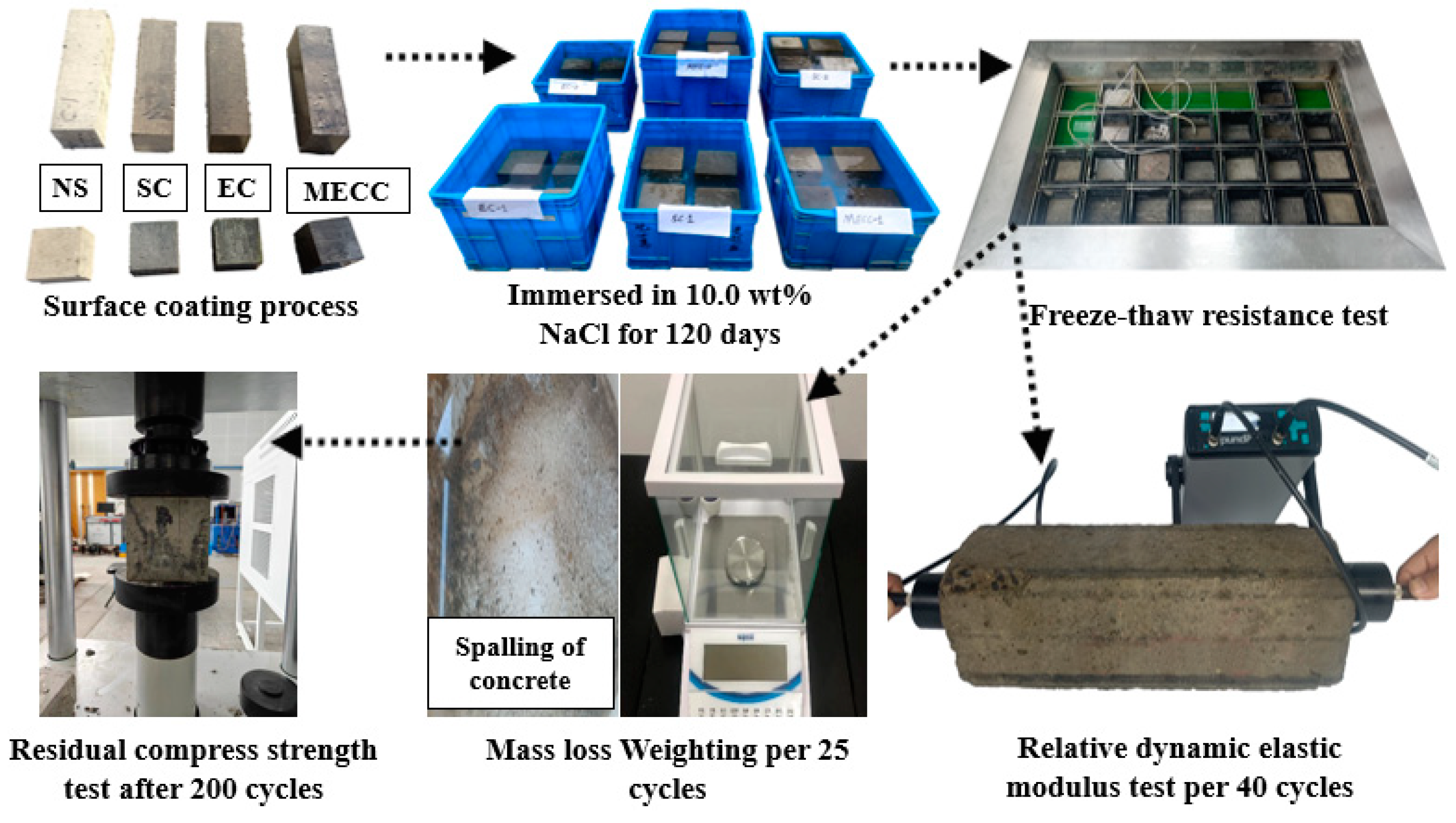
Figure 2.
Mass loss under different freeze-thaw cycles.
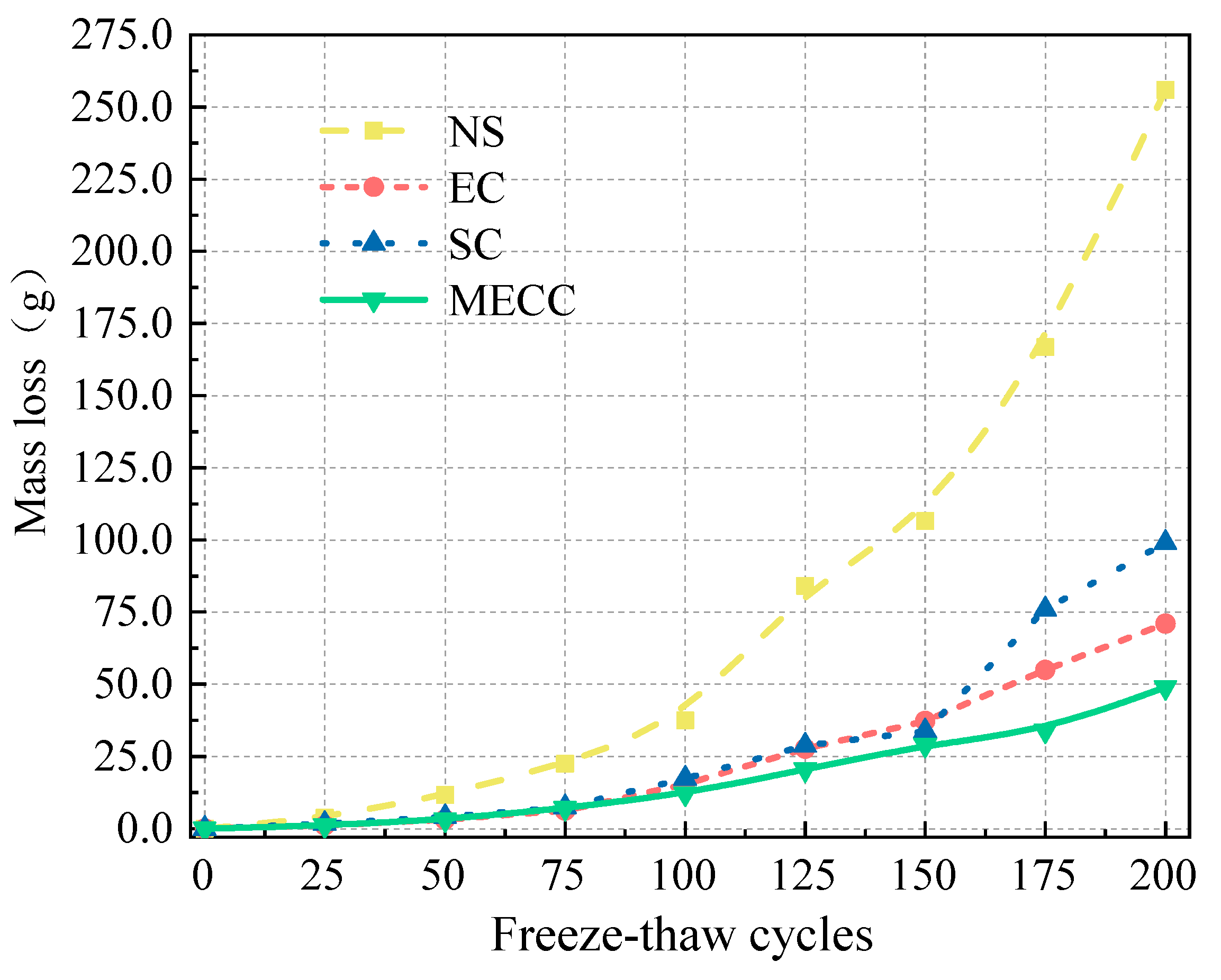
Figure 3.
RDEM under different freeze-thaw cycles.
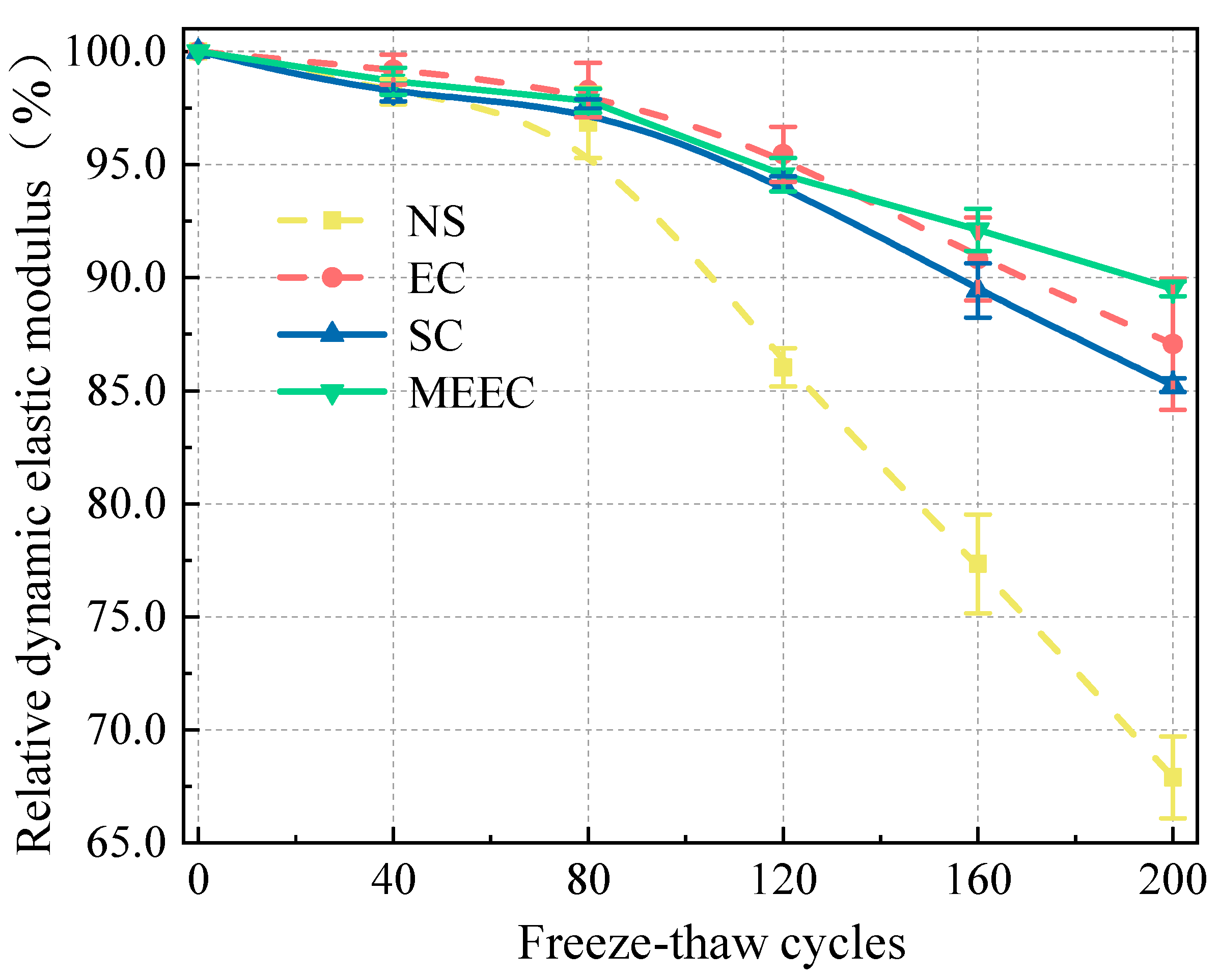
Figure 4.
Residual compressive strength after 200 freeze-thaw cycles.
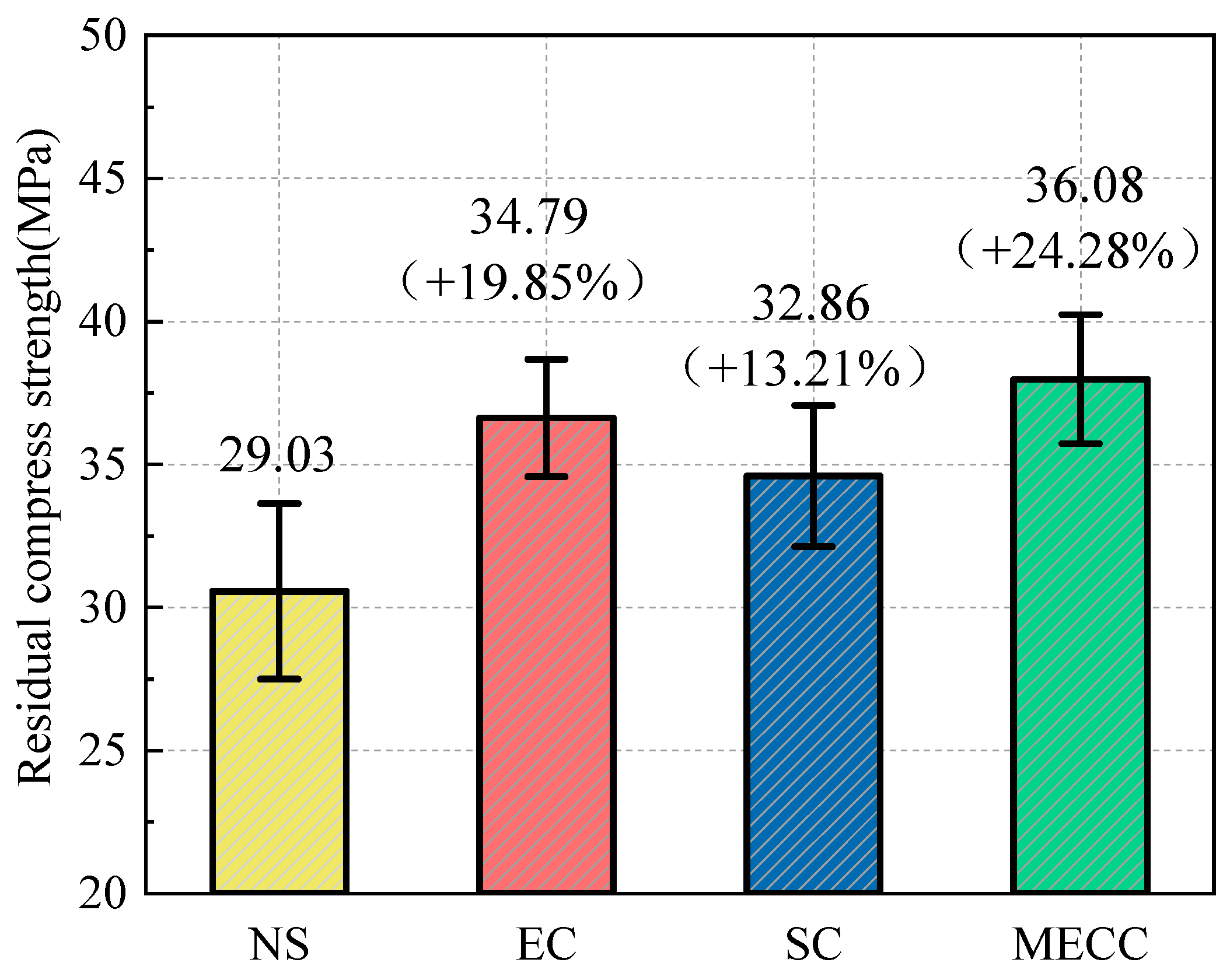
Figure 6.
Relationship between water absorption rate and immersion time.
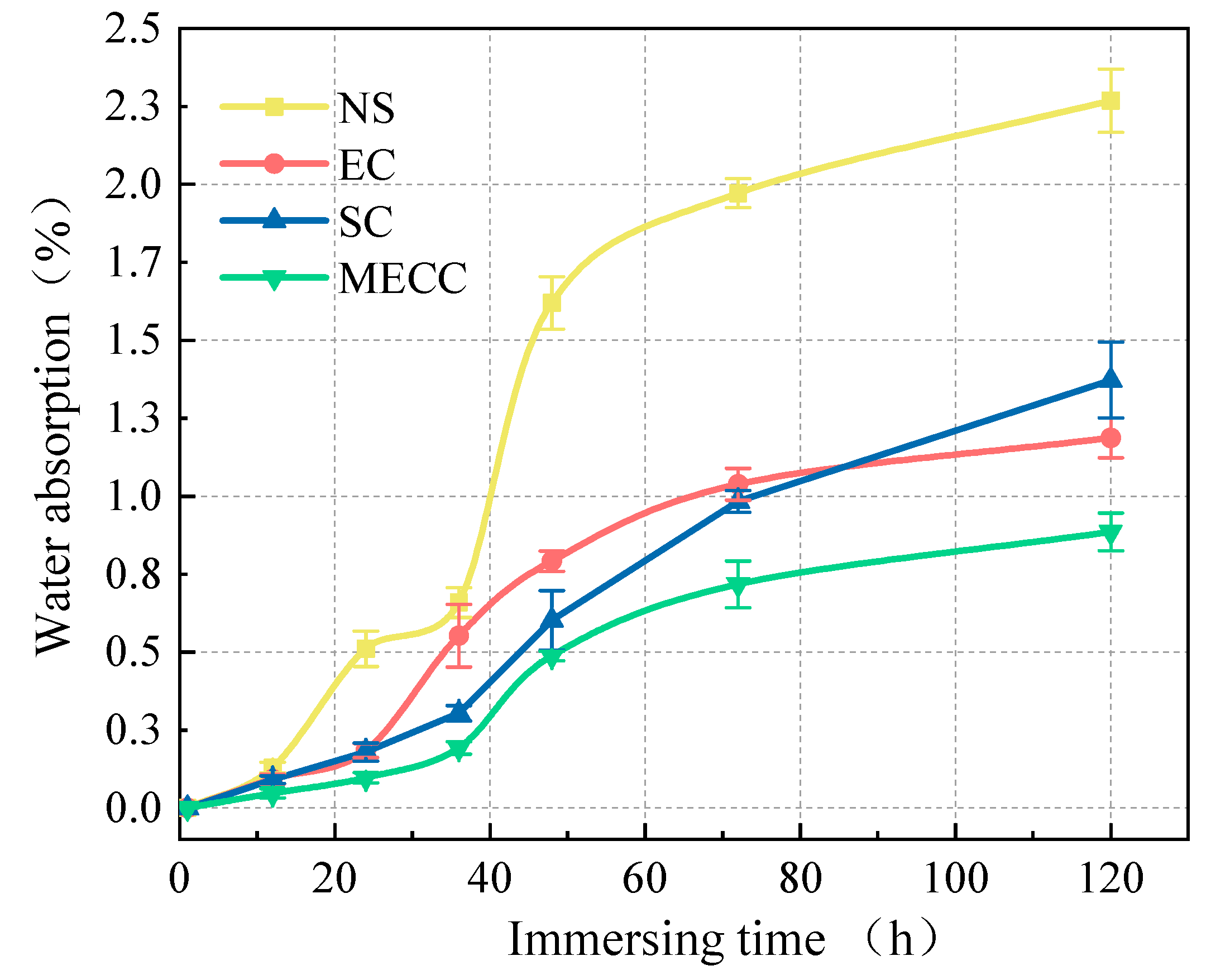
Figure 7.
Macro-morphology characteristics of the specimens when exposed to corrosive ions.
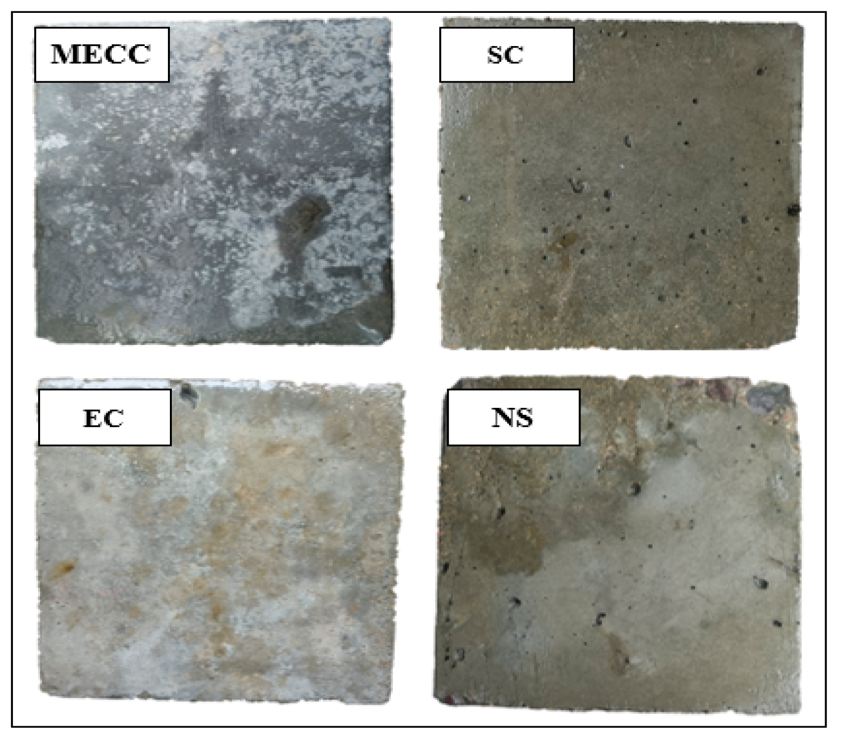
Figure 8.
Pore structure of the specimens after coating treatment: (a) Log differential intrusion; (b) Cumulative intrusion.
Figure 8.
Pore structure of the specimens after coating treatment: (a) Log differential intrusion; (b) Cumulative intrusion.
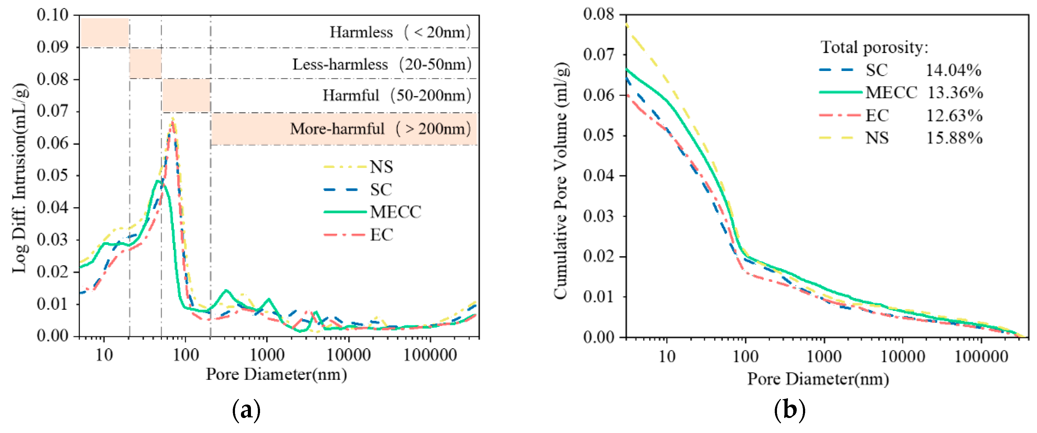
Figure 9.
Reconstruction of the CT scanned inner structure of specimens.
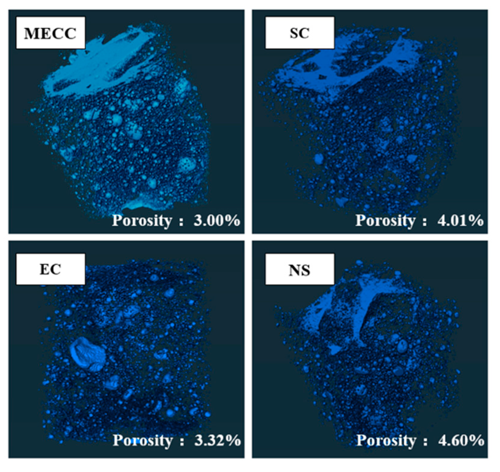

Table 1.
Chemical composition of used Portland cement (%).
| SiO2 | Al2O3 | Fe2O3 | CaO | MgO | SO3 | Na2O | f-CaO | C3S | C2S | C3A (C4A3) | C4AF | |
|---|---|---|---|---|---|---|---|---|---|---|---|---|
| 22.71 | 4.57 | 2.85 | 66.10 | 1.90 | 1.37 | 0.50 | 0.92 | 58.06 | 18.71 | 5.94 | 10.82 | |
Table 2.
Mixing ratio of cement concrete specimens (kg/m3).
| Cement | Water | Sand | Gravel | Water reducer (%) |
|---|---|---|---|---|
| 475 | 220.0 | 620 | 1100 | 0.8 |
Table 3.
Methods of using specimens with different coatings.
| Group | Coating type | Treatment procedure |
|---|---|---|
| NS | None coating | - |
| EC | Epoxy coating | Apply the first treatment after cleaning the concrete surface, and apply the second after an interval of 5 minutes, material dosage 0.40L·m-2 |
| SC | Silane coating | Clean the concrete surface and spray three times in succession, material dosage 0.40L·m-2 |
| MECC | Modified Epoxy Composite coating | Apply 3 times treatment with a brush after surface cleaning, material dosage 0.35L·m-2 |
Table 4.
RCPT evaluation criteria for chloride ion permeability.
| Electric flux/C | >4000 | 2000~4000 | 1000~2000 | 100~1000 | <1000 |
|---|---|---|---|---|---|
| Chloride ion permeability | High | Medium | Low | Very low | Neglected |
Table 5.
Variations of 6 h coulomb electric flux of specimens.
| NS | EC | SC | MEEC | |
|---|---|---|---|---|
| Electric flux /C | 2128 | 283 | 367 | 157 |
| Chloride ion permeability | Medium | Very low | Very low | Very low |
Table 6.
Pore structure test results.
| Group | Proportion of different diameter pores (%) | |||
|---|---|---|---|---|
| <20 nm | 20–50 nm | 50–200 nm | >200 nm | |
| NS | 28.32% | 23.10% | 20.81% | 27.74% |
| SC | 25.76% | 23.60% | 24.58% | 26.03% |
| EC | 28.76% | 23.20% | 25.05% | 22.97% |
| MECC | 35.96% | 30.86% | 13.48% | 19.68% |
Table 7.
Pore structure test results.
| Group | NS | SC | EC | MECC |
|---|---|---|---|---|
| Porosity (%) | 4.60 | 4.01 | 3.32 | 3.00 |
| Average pore diameter (mm) | 0.1287 | 0.1268 | 0.124 | 0.1262 |
| Average pore surface area (mm2) | 0.0222 | 0.0201 | 0.0132 | 0.0137 |
| Average pore volume (mm3) | 0.1734 | 0.167 | 0.1244 | 0.1273 |
| Pore proportion (<0.1 mm3, %) | 95.05 | 95.48 | 95.95 | 95.5 |
| Number of pores (0.1-1.0 mm3) | 2344 | 1833 | 1929 | 2181 |
| Pore proportion (0.1-1.0 mm3, %) | 0.275 | 0.268 | 0.268 | 0.277 |
| Pore volume (0.1-1.0 mm3, mm3) | 644.88 | 492.564 | 512.63 | 604.31 |
| Number of pores (≥1.0 mm3) | 361 | 301 | 305 | 334 |
| Pore proportion (≥1.0 mm3, %) | 16.55 | 16.8 | 12.14 | 10.05 |
| Pore volume (≥1.0 mm3, mm3) | 5974.55 | 5056.8 | 3702.7 | 3356.7 |
Disclaimer/Publisher’s Note: The statements, opinions and data contained in all publications are solely those of the individual author(s) and contributor(s) and not of MDPI and/or the editor(s). MDPI and/or the editor(s) disclaim responsibility for any injury to people or property resulting from any ideas, methods, instructions or products referred to in the content. |
© 2025 by the authors. Licensee MDPI, Basel, Switzerland. This article is an open access article distributed under the terms and conditions of the Creative Commons Attribution (CC BY) license (http://creativecommons.org/licenses/by/4.0/).
Copyright: This open access article is published under a Creative Commons CC BY 4.0 license, which permit the free download, distribution, and reuse, provided that the author and preprint are cited in any reuse.


