Submitted:
30 January 2025
Posted:
30 January 2025
Read the latest preprint version here
Abstract
Recent years have seen increasing attention on autonomous decentralized microgrids that are disaster-resistant and suitable for local consumption of locally generated renewable energy power. Although various methods have been discussed for achieving microgrids through autonomous decentralized cooperative control, there are few reports that have reached the stage of field testing. In this study, we propose a novel configuration method for DC microgrids, where storage batteries are distributed and directly connected to the DC baseline. We have built a testbed to demonstrate the operation of the DC microgrid through autonomous decentralized cooperative control. Our method simply employs the Droop characteristics inherent in batteries, and we introduce the new concept of a "weakly-coupled grid." This approach allows the realization of microgrids with autonomous decentralized cooperative control without the need for advanced and complex grid control technologies such as that with AI, and with a simple configuration. Additionally, by directly connecting batteries to the baseline, we introduced a grid stabilization method by imparting electrical inertia to the baseline. This paper describes the construction method, the operation principle, and the safe and stable operational methods for autonomous decentralized microgrids using this approach, aiming to serve as a guide for those who wish to build autonomous decentralized controlled microgrids in practice.
Keywords:
DC microgrid
; autonomous decentralized cooperative control
; directly connecting batteries to the baseline
; Droop control
; electrical inertia
; weakly-coupled grid
1. Introduction
In recent years, large-scale and catastrophic natural disasters have become increasingly frequent in many countries around the world. The primary cause of these disasters is believed to be global warming, and the reduction of greenhouse gas emissions, such as CO2, has become an urgent issue. Therefore, efforts are being made to shift from fossil fuels to renewable energy sources in power generation. However, there are several challenges to overcome. Power generation by renewable energy, such as solar or wind power, is intermittent and unstable, and as the ratio of power generated by renewable energy increases, it can destabilize power grid systems. Furthermore, there is insufficient capacity in the existing power grids to accommodate additional renewable energy power generation. Additionally, the existing power grid, which relies on large-scale centralized power generation and long-distance transmission, has proven to be vulnerable to major disasters.
Against this backdrop, regional microgrids based on the principle of local production and consumption of electricity are gaining attention [5,6]. Particularly in residential areas, direct current (DC) microgrids that connect small power generators using renewable energies, such as solar panels and wind turbines, and storage batteries through DC baselines are drawing keen interest [7]. Although DC microgrids require the installation of dedicated power lines, they are simpler to control and offer greater flexibility in grid configuration compared to alternative current (AC) grids. Field testing and social implementations have already been conducted in various parts of the world, although control methods and baseline voltages vary. Moreover, even if a microgrid is constructed, maintaining and operating it over the long term is not easy.
This paper focuses on the operating principles, construction methods, control methods, and safety measures of DC microgrids with autonomous decentralized cooperative control (ADCC) which enable practical use. Specifically, we propose an autonomous decentralized cooperative controlled DC microgrid achieved by directly connecting distributed batteries to the baseline. We have built an experimental testbed for this type of microgrid and have successfully operated it stably for over three years. We also share the knowledge and challenges gained from this experience, hoping to provide useful insights for those planning to construct microgrids in the future.
2. Autonomous Decentralized Cooperative Controlled DC Microgrid
Microgrid control methods include centralized control, decentralized control, hierarchical control, and various other approaches [4,5,6,7]. The centralized control method, as shown in Figure 1(a), is used in existing power grids and involves a centralized controller (such as a central control center) that monitors and controls the entire grid. Several devices within the grid are connected to the centralized controller via communication lines, allowing for unified management of the grid. This method enables optimization across the entire grid. However, if the centralized controller fails or the communication lines are disrupted, the entire grid becomes uncontrollable, making it vulnerable to large-scale disasters.
In contrast, ADCC, as depicted in Figure 1(b), is a unique control method that does not involve a centralized controller and communication lines that connect devices. Each device connected to the grid independently makes decisions and controls itself. This method lacks the framework to monitor the entire grid, making overall grid optimization challenging and limiting it to local or partial optimization of grids. Nevertheless, even if part of the grid is damaged, the remaining parts can still function to some extent, making this method effective during disasters. Additionally, this approach allows for relatively easy modifications and expansions of the grid, enabling the creation of a flexible and scalable grid.
How the grid is controlled under such a system may be a subject of inquiry. The key is to establish certain rules for grid usage, with each device adhering to these rules while operating within the grid. For example, in a DC grid, the rule might be that each device acts as keeping the baseline voltage within a certain normal range. Power generators, for instance, would feed power into the baseline to maintain the voltage within the normal range, and loads would draw power accordingly. If there is a risk of the baseline voltage deviating from this range, devices would self-regulate their operations. For example, if the baseline voltage is high and feeding power into it would exceed the normal range, generators would refrain from supplying power despite having the potential to generate electricity. Similarly, if the baseline voltage is low and drawing power from it would drop it below the normal range, loads would not be operated.
Such ADCC grid might appear imperfect due to its limitations in overall optimization. However, output suppression of renewable energy power generation in existing grids is already common. The critical point is to minimize the frequency of such occurrences. The grid should be designed to ensure that these events are exceedingly rare.
By introducing such a system, it is possible to maintain and operate the grid without centralized controllers or communication lines. In essence, this system establishes rules for proper grid utilization, with each device adhering to these rules while exercising self-restraint. This approach creates a democratic grid that can be effectively maintained and managed.
3. Droop Characteristics Inherent to Batteries
In microgrids that emphasize local production and consumption of electricity through distributed power sources, it is essential to establish a mechanism whereby multiple distributed power sources can cooperate to maintain the grid. One method to autonomously control multiple distributed power sources in a cooperative manner is through Droop control. This method is also utilized for the coordinated operation of synchronous power generators in existing power grids, allowing multiple synchronous generators to share loads while maintaining coordinated power generation.
Specifically, each synchronous generator has Droop characteristics, where the rotational speed of the generator decreases, and the output voltage or frequency drops as the load ratio increases. This allows adjacent synchronous generators to share part of the increased load, thus equalizing the load ratio.
In DC grids, distributed power sources like generators or batteries use DC/DC converters with Droop characteristics to achieve coordinated operation. However, as the number of distributed power sources increases, the number of Droop parameters to be controlled also increases, complicating the control process. Therefore, we have devised a method focusing on the inherent Droop characteristics of the batteries themselves to achieve ADCC operation. This method does not use DC/DC converters; instead, batteries are directly connected to the baseline to achieve ADCC.
The Droop characteristics of inherent to batteries can be formulated from the equivalent circuit of batteries. The basic equivalent circuit of a battery consists of an electromotive force E in series with an internal resistance ri as shown in Figure 2(a). If a load resistance is connected, and the value of the load resistance RL equal to ri, the battery can deliver maximum power, defining a load rate of 100%. When a load RL of any value is connected, the load rate α is given by:
Meanwhile, the terminal voltage Vt of the battery, given the electromotive force E, is:
The relationship between the load rate α and the terminal voltage Vt is thus:
This relationship is depicted in Figure 2(b), representing the Droop characteristics of inherent batteries. Generally, as the load rate increases (i.e., as the output current increases), the terminal voltage drops due to the voltage drop across the internal resistance. However, the Droop coefficient changes its sign depending on whether the value of the load resistance is greater than or less than the internal resistance of the battery.
To achieve ADCC, it is necessary to use the region where the Droop coefficient is negative, i.e., the upper half of the graph, when the load resistance is greater than the internal resistance of the battery. Moreover, where the load rate is 50% or less, a nearly linear relationship is observed between the load rate and the terminal voltage, enabling stable Droop operation.
The equation (3) indicates that the Droop characteristics of the battery do not depend on the value of internal resistance. Consequently, even if the battery deteriorates and its internal resistance increases, as long as the terminal voltage remains constant (which equals the baseline voltage in direct connection), the load rate will be maintained at the same value as when the battery was new. Furthermore, even with a mix of different types of batteries, if their electromotive force (equal to the open-circuit voltage) is uniform, the load rate can be equalized across the batteries.
Thus, by directly connecting batteries of the same type and equal terminal voltage to the baseline, the inherent Droop characteristics of the batteries can be leveraged for cooperative operation.
Measurement of the internal resistance of a lithium iron phosphate (LiFePO4) battery rated at 51.2 V, 40 Ah showed that the internal resistance was approximately 75 mΩ, depending on the state of charge (SoC) and the magnitude of the discharge current. Therefore, the load rate for a 1C (40 A) discharge of this battery is approximately 12%, and under normal usage conditions, the load rate remains relatively low, which allows for effective Droop control.
Thus, by directly connecting batteries with matched electromotive force values to the baseline, ADCC can be achieved using the batteries’ inherent Droop characteristics.
4. Stabilizing Grid by Electrical Inertia
By directly connecting the battery to the baseline, the baseline can be endowed with electrical inertia. Electrical inertia plays a crucial role in the stability of the grid and is also utilized in existing power grid systems. When using electrical appliances with high inrush power (starting power) at home, although the current is greater than the rated current when the moment of the switch is turned on, the appliance can start without the power line going down because a large electrical inertia extends to the household power plug.
In existing power grid, there were essentially no energy storage facilities, so it was necessary to always balance power generation and consumption (the principle of simultaneous supply and demand). Therefore, a mechanism was needed to cope with instantaneous increases in power load, and in the grid, this is handled by the generators at the power plants. In other words, the source of electrical inertia is the rotational kinetic energy stored in the heavy turbines of generators at thermal or hydroelectric power plants. This energy is converted into electrical energy and released into the grid instantaneously (within a few microseconds) in response to sudden increases in power consumption, thus accommodating the sudden spike in power load. Wind turbines in wind power generation do not have such heavy turbines storing kinetic energy and synchronization mechanism, which is why the introduction of wind power generation is feared to lead to a decrease in electrical inertia in existing power grids.
This applies to DC grids as well, where electrical inertia is the capability to withstand sudden changes in power load, contributing to grid stabilization. From this perspective, electrical inertia in a DC grid can be considered the maximum power that can be instantaneously extracted from a point on the baseline or power line. “Instantaneous” here specifically means a period ranging from a few seconds to at most a few tens of seconds, differing from power sustainability over several hours and referring solely to instantaneous force. It is a very short period sufficient to start up home appliances requiring high inrush power. Power sustainability for running appliances for hours is related to battery capacity and is different from electrical inertia.
In DC microgrids that directly connect batteries to the baseline, the batteries can assume this electrical inertia to some extent. The extent depends on the type and size of the battery used (mainly internal resistance). Large electrical inertia cannot be expected from batteries with high internal resistance. Although discharge response speed of a battery depends on the type of battery, for lithium-ion batteries, it is less than a few microseconds. Therefore, since electrical energy is transmitted through power lines at almost the speed of light, electrical inertia reaches the power load connected to the baseline within a few microseconds of the switch being turned on.
However, if a DC/DC converter for voltage conversion is interposed between the battery and the baseline, the response speed decreases due to electrical control of the DC/DC converter, and the maximum current of the device limits the inertia, potentially not fully transmitting the battery’s inherent electrical inertia to the baseline. Hence, the reason for directly connecting batteries to the baseline.
When directly connecting batteries to the baseline, since the baseline also has electrical resistance (conductor resistance), electrical inertia depends on the thickness of the power line in the baseline and is greater closer to the battery and smaller further away from it. Figure 3 shows the calculation for this when a 14 square meters (SQ) cross-linked Polyethylene insulation Vinyl sheath (CV) cable was used as the baseline, indicating that if batteries of the same total capacity are used, it is better to divide and evenly distribute them along the baseline rather than connecting a large capacity battery at one point, to ensure a uniformly large electrical inertia across the baseline. However, it is assumed that the internal resistance of a single battery before it is divided is 0.1 Ω, and that when the battery is divided, the internal resistance increases in proportion to the number of divisions.
5. Local Control by Weakly-Coupled Grid
In existing power grids, generators at power plants, transformers at substations, and power loads at consumers are electrically strongly coupled, forming a tightly coupled grid. In contrast, our proposed battery-connected DC grid is a loosely coupled grid where each device is electrically weakly coupled. The strength of the electrical coupling between each device is an indicator of the capacity of the power lines connecting those devices, relative to the rated power of each device (generation power for generators, charge/discharge power for batteries, and consumption power for power loads). Therefore, the lower the electrical resistance of the power lines connecting the devices, the higher the voltage, and the larger the allowable current, the stronger the coupling. As a result, our proposed battery-connected DC grid is a weakly coupled grid, allowing for small deviation of the baseline voltage to which each device is connected, even if they are connected by the baseline.
The strength of the coupling between devices is important for realizing ADCC operation. For instance, when charging a battery with the power generated by solar panels, an MPPT charge controller is usually used, however when directly connecting the battery to the baseline, this control needs to be local and should not affect adjacent devices as shown in Figure 4. If the adjacent devices are electrically strongly coupled, this control signal could reach the neighboring devices, causing interference and potential breakdown of the MPPT control. Thus, by having each device weakly coupled electrically, each device can maintain the independence of ADCC in the short term while allowing relatively slow power exchange between devices in the long term.
To maintain the locality of each device’s control, the frequency transmission characteristics of the baseline can be also utilized. CV cables used for the baseline can transmit low-frequency electrical signals including DC but have significant attenuation for high-frequency electrical signals. Thus, control signals with short time constants (a few milliseconds or shorter) can attenuate while propagating through the cable, preventing them from reaching neighboring devices. Figure 5 shows the frequency transmission characteristics of a CV cable with a length of 100 meters and a cross-sectional area of 14 SQ, calculated based on the line constants. Although it depends on the length and thickness of the cable between devices, attenuation is significant in the high-frequency range above tens of kHz. This characteristic is only of the cable, so if a battery is directly connected to the baseline, the battery can be seen as a capacitor, further lowering the cutoff frequency. Therefore, if control is performed with a time constant shorter than a few milliseconds, the control will be localized and will not affect near devices.
On the other hand, if a voltage difference occurs between devices, for example, even if a voltage difference of only 1 V occurs between devices connected by a 100-meter-long 14 SQ CV cable, about 200 W of power is transported when the reference line voltage is 50 V, and about 1.5 kW of power is transported when the reference line voltage is 400 V, resulting in the equalization of SoC of distributed batteries.
Therefore, in a weakly-coupled grid where batteries are directly connected to the baseline, ADCC and electrical inertia act only locally on the device, while in the long term, slow power exchange between devices and equalization of SoC of distributed batteries occurs.
6. Demonstration Experiment
To verify the feasibility of the battery directly connected DC microgrid, we constructed a testbed of the microgrid on our university campus as shown in Figure 6, and it has been operating stably for over three years. Power boxes, which house LiFePO4 batteries with a rated terminal voltage of 51.2 V, are installed on the rooftops of four school buildings, namely Building 1-3 and Central Building. These are connected by a power baseline made up of 14 SQ CV cables. Additionally, 800 W solar panels are installed on the rooftops of Building 1-3 and connected to the batteries within each power box through MPPT charge controllers. The baseline is laid in a T-shape with the Central Building serving as a hub, and Building 1-3 being are the endpoints of the baseline. The Central Building hub is equipped with a battery having double the capacity (240 Ah) compared to the batteries in Building 1-3, although it does not have solar panels installed.
The reason for installing the power boxes outdoors on the rooftops of school buildings is due to the fire risk posed by lithium-ion batteries, adherence to fire safety regulations, and the anticipation of replacing existing power distribution grids with DC baselines in the future, where distributed storage batteries are envisioned to be installed at pole transformer locations. Consequently, the power boxes are waterproof, lined with insulation materials on the inside, and covered with a silver sheet. Despite this, the batteries have shown no significant damage or degradation even though the outdoor temperatures can drop below freezing in winter and exceed 40°C during summer days. The power boxes also contain MPPT charge controllers, DC/AC inverters, mini-PCs for monitoring, and switching hubs for wired network link, all of which continue to function normally.
This microgrid operates off-grid, entirely powered by renewable energy (solar power). The electrical load consists of distributed micro datacenters that consume approximately 100 W power steadily, located on the rooftops of Building 1-3. When the batteries’ SoC is sufficiently high, the micro electric vehicles (EVs) are occasionally charged. Table 1 shows the specifications of the microgrid.
The devices connected to this grid operate autonomously in a distributed cooperative manner without exchanging information via communication lines. For example, the solar panel charge control is programmed to switch to float mode at 55.6 V to prevent overcharging and damaging batteries if the terminal voltage of the connected batteries exceeds 56 V; otherwise, MPPT control is applied if the terminal voltage is 56 V or less.
Additionally, when the battery terminal voltage drops below 51 V, a low voltage alarm is sent to the administrator via email, leading to manual suppression of power load usage. If the battery voltage continues to drop further, the battery management system (BMS) within the battery stops output to the terminals to prevent over-discharge damage. As an off-grid power source, this microgrid handles such situations by disconnecting power loads before reaching this final measure. Therefore, the baseline voltage fluctuates within the range of 51 to 56 V even during normal operation, requiring power loads to be designed to operate within this voltage range. In practice, the DC/AC converters used in the system can operate within this voltage range. (For reference, the voltage range of Japan’s household 100 V indoor wiring is regulated by Article 38 of the Electricity Business Act Enforcement Regulations to be within the range of 95 to 107 V, not exceeding ±6 V of 101 V). Since the batteries of each power box are directly connected to the baseline, any voltage difference at the terminal voltage will naturally be equalized through power exchange via the baseline.
The charge controllers for solar panels are USB-connected to the mini-PCs within the power boxes, and through wired LAN laid along the power baseline, the generated power, charging power, and temperature inside the box, etc. can be monitored in real-time. This setup is solely for monitoring purposes and does not involve any specific control. Figure 7 shows the monitoring screen of the microgrid, allowing monitoring at 1-second interval for the battery terminal voltage, and at 1-minute intervals for the battery temperature, solar panel generation power, power consumption of the connected loads, etc.
The LiFePO4 batteries used in our microgrid are configured with 16 series-connected and 12 parallel-connected 26650 cells (3.2 V, 3.3 Ah). The relationship between the terminal voltage and SoC (approximate) at no load is estimated as shown in Figure 8. Therefore, the SoC of the batteries near the measurement point of baseline can be roughly estimated from the baseline voltage.
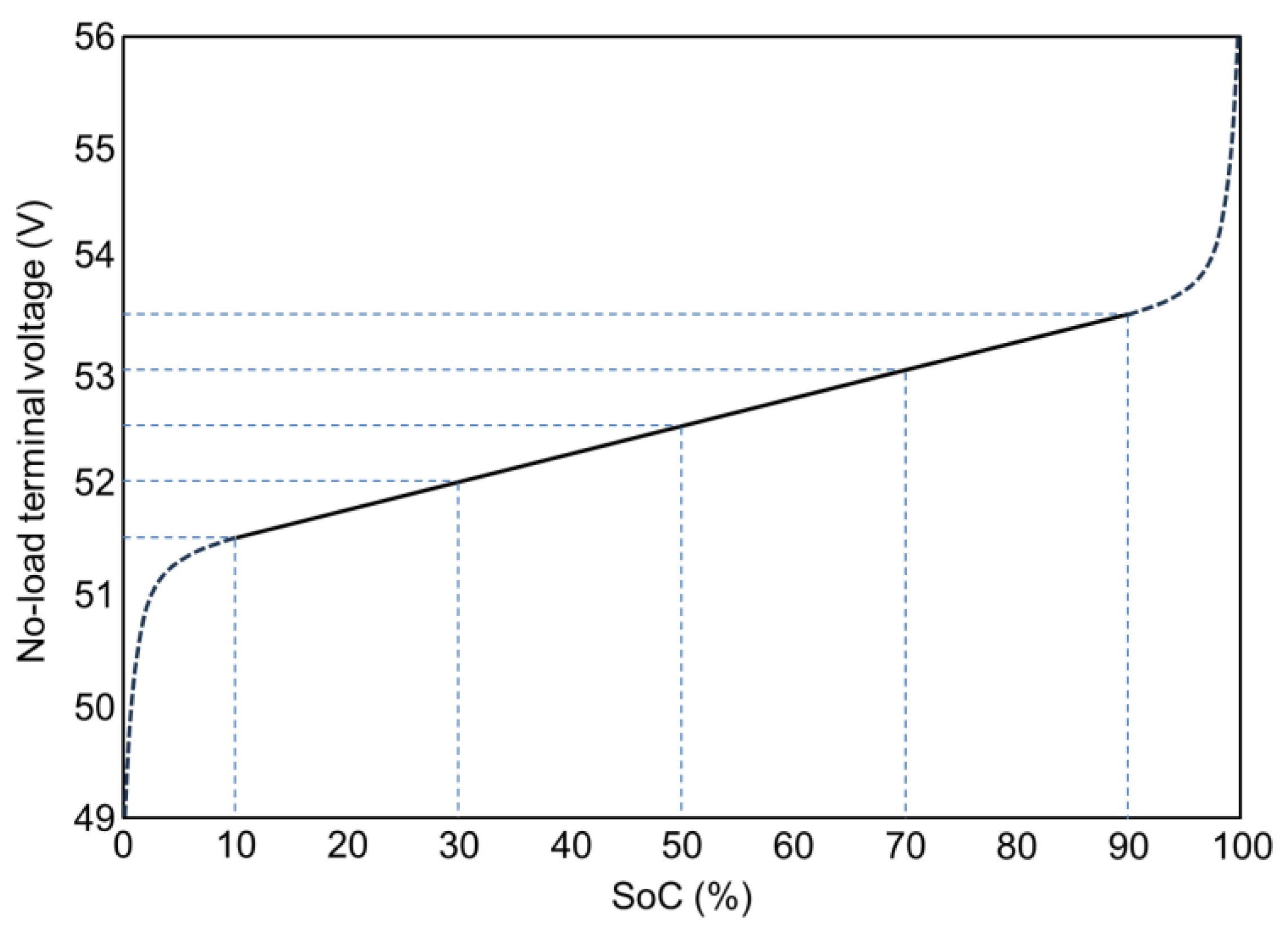
Figure 8.
Relationship between battery terminal voltage and SoC.
Figure 9 shows the transition of solar power generation and battery terminal voltage measured over one month in January 2023 [8]. During this period, the micro data center as the main power loads was not yet fully operational, and EV charging was sporadic, keeping the batteries nearly fully charged. It can be seen that charge control limited the battery terminal voltage to 56 V during sunny daytime, and the terminal voltages of each battery naturally equalized even if temporarily uneven due to EV charging.
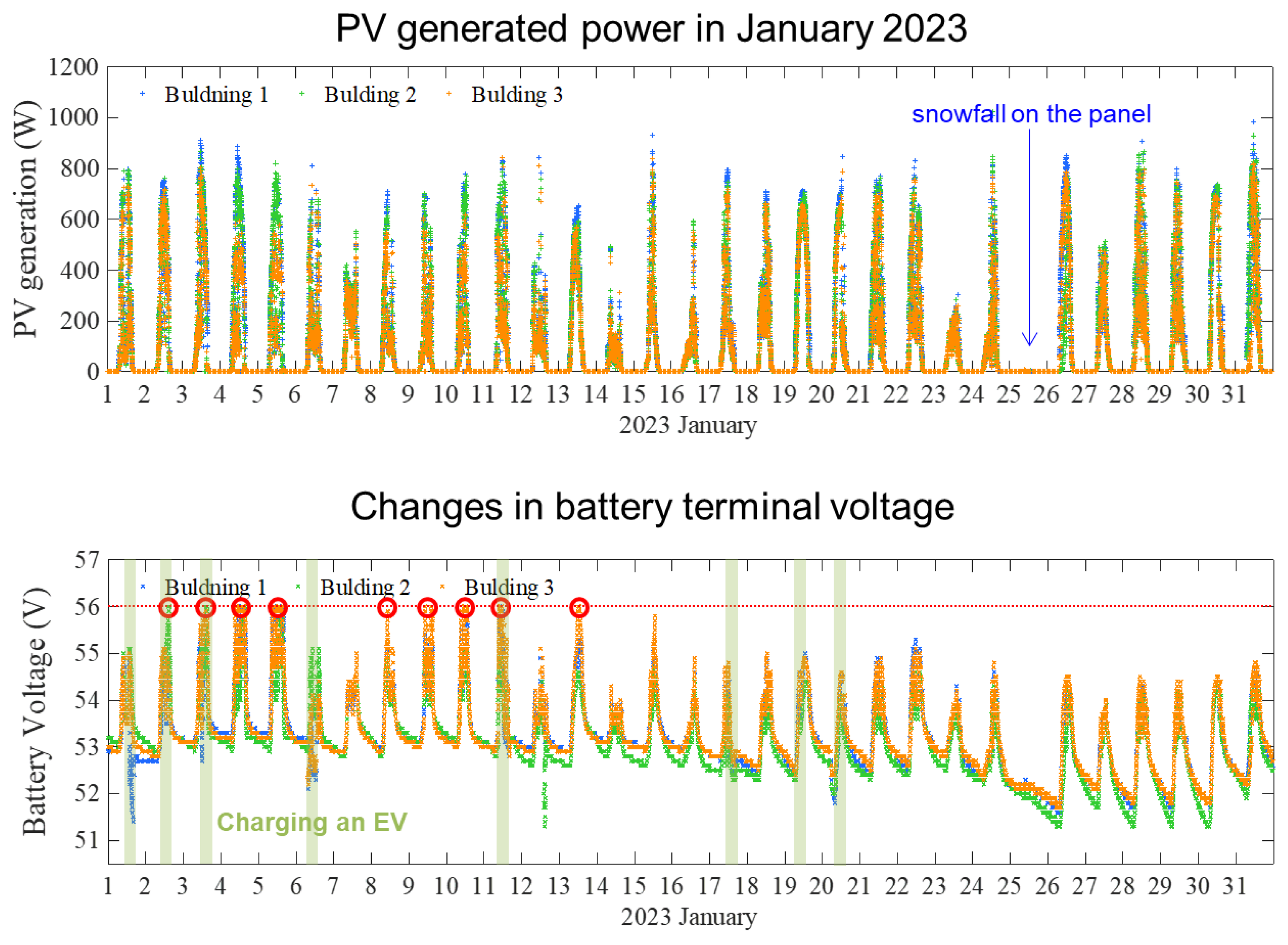
Figure 8.
System operation record for one month in January 2023.
7. Configuration of the DC Baseline
The method of configuring DC baselines with distributed and directly connected batteries is shown on Figure 9. In this configuration, small batteries are distributed and directly connected to the positive and negative baselines, with the midpoint of those batteries grounded. For example, in the case of a baseline voltage of about 50 V, two batteries with an equal terminal voltage of 25 V are connected in series, and the midpoint is grounded. This enhances resistance to lightning strikes and electromagnetic pulse (EMP) attacks, and ensures safety against leakage currents. Power generation equipment such as solar panels and power load devices are basically connected to the positive and negative lines of the baseline to send or receive power. Therefore, if there is no ground fault causing leakage on one of the baseline lines, the same magnitude of current flows in the opposite direction in the positive and negative lines, preventing any external leakage magnetic field. Additionally, if a ground fault occurs, the imbalance in current flow between the positive and negative lines can be easily detected by a clamp-type leakage detector or similar device.
In this setup, the two lines of the baseline are fixed at +25 V and −25 V with respect to the ground potential, so in the unlikely event of electric shock due to leakage, the voltage shock will not exceed this value. Of course, if both poles of the baseline are touched, one will experience the full 50 V baseline voltage.
In the event of a direct lightning strike on the baseline, a momentary high voltage will occur, possibly damaging storage batteries and equipment near the strike point. However, the damaged storage batteries could serve as a fuse, potentially protecting other equipment. In the case of induced lightning, the directly connected storage batteries function as large capacitors, absorbing the surge current caused by the lightning. Similarly, the effects of magnetic storms or EMP attacks are mitigated due to this function.
Since the same magnitude of current flows in both the positive and negative lines of the baseline, the positive and negative sides of the directly connected batteries always maintain the same SoC and equal voltage magnitude with opposite polarity relative to the midpoint. To correct any imbalance, a cell balancer with correction capabilities is desirable [9].
When directly connecting batteries to the baseline, it is necessary to match the terminal voltage to the baseline voltage. This is not particularly difficult since various types of batteries with different terminal voltages are widely available in the market. The LiFePO4 batterie used in our constructed microgrid have a cell voltage of 3.2 V, with many commercially available options of 25.6 V (8 cells in series) or 51.2 V (16 cells in series). Therefore, as shown in the figure, by connecting these in series, storage batteries that correspond to baseline voltages of 50 V or 400 V can be configured.
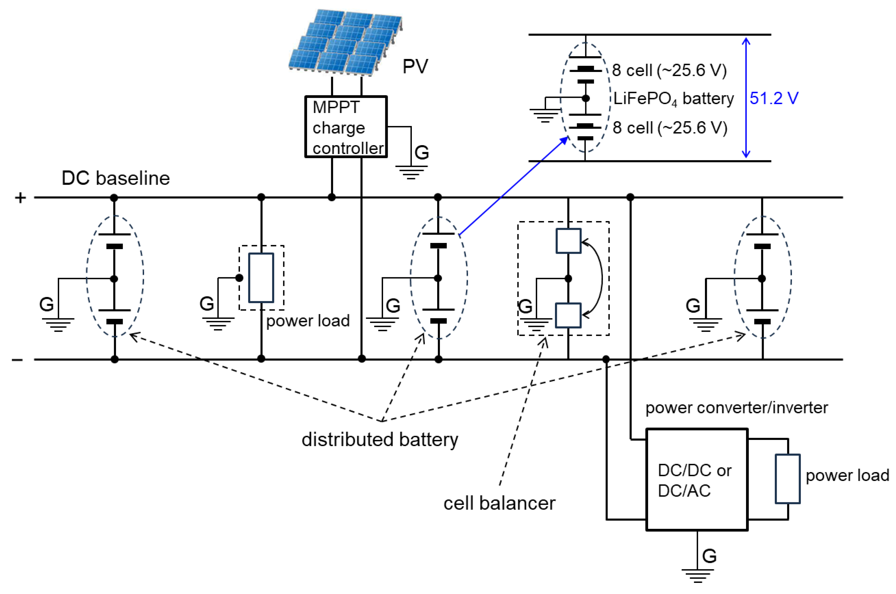
Figure 9.
Configuration of the DC baseline.
8. Safety Measures for the Microgrid
In the proposed DC grid, which is characterized by the distribution and direct connection of batteries to the baseline to provide electrical inertia, safety measures are indispensable because large currents flow during ground faults or short circuits in the baseline, potentially leading to major accidents. Of course, existing AC power grids are also equipped with circuit breakers (CB) and fuses in various locations to prepare for such accidents. While existing ultra-high voltage circuits in power grids require special CBs to cut the arc discharge that occurs during circuit disconnection, the DC microgrid envisioned here has a baseline voltage of around several hundred volts, so such special CBs are not considered necessary. However, since many commercially available CBs are for AC use, CBs that can be used with DC are required. When a short circuit or ground fault occurs in the baseline, an abnormal large current flows momentarily. The mechanism to detect this and cut the circuit is the same as existing ones, but a considerably large current capacity (hundreds of amperes) is required.
As an example, various safety measures for the DC grid with a baseline voltage of 400 V are shown on Figure 10. By installing overcurrent CBs that detect and cut overcurrent at various locations in the baseline, the shorted section can be isolated on both sides from the baseline, preventing accident escalation. In this way, the installation of overcurrent CBs along the baseline is feasible only in weakly coupled grids. In contrast, in strongly coupled existing grids, it is uncommon to install overcurrent CBs in the middle of transmission or distribution lines.
At the very least, as shown in the figure, overcurrent CBs should be installed at all connection points between the distributed batteries and the baseline. In our constructed microgrid, 63 A CBs are installed between each battery and the baseline. Therefore, it is possible to replace each battery (hot swap) without stopping the grid, and CBs are also installed between each power box and the baseline, allowing each power box to be freely connected or disconnected from the baseline.
Furthermore, when a short circuit or ground fault occurs in the baseline, a large discharge current occurs from the batteries directly connected to the nearby baseline, leading to an abnormal drop in terminal voltage. Therefore, it is also effective to install abnormal voltage CBs that detect and cut the circuit upon detecting abnormal battery terminal voltage. This is also effective for protecting batteries from overcharging or over-discharging. Some lithium-ion batteries are equipped with a BMS function that disconnects from the terminals to protect the battery when the terminal voltage drops below a specified value.
On the other hand, ground fault accidents can be addressed with a breaker based on the same principle as commercially available AC residual current devices (RCD). In a neutral point grounded DC baseline with the baseline voltage’s neutral point grounded as shown in the figure, the magnitude of current flowing in the positive and negative sides of the baseline should normally be equal, but if a ground fault occurs somewhere, this becomes unbalanced and can be detected by a conventional clamp meter or RCD. Therefore, countermeasures can be taken by installing such devices at various locations along the baseline.
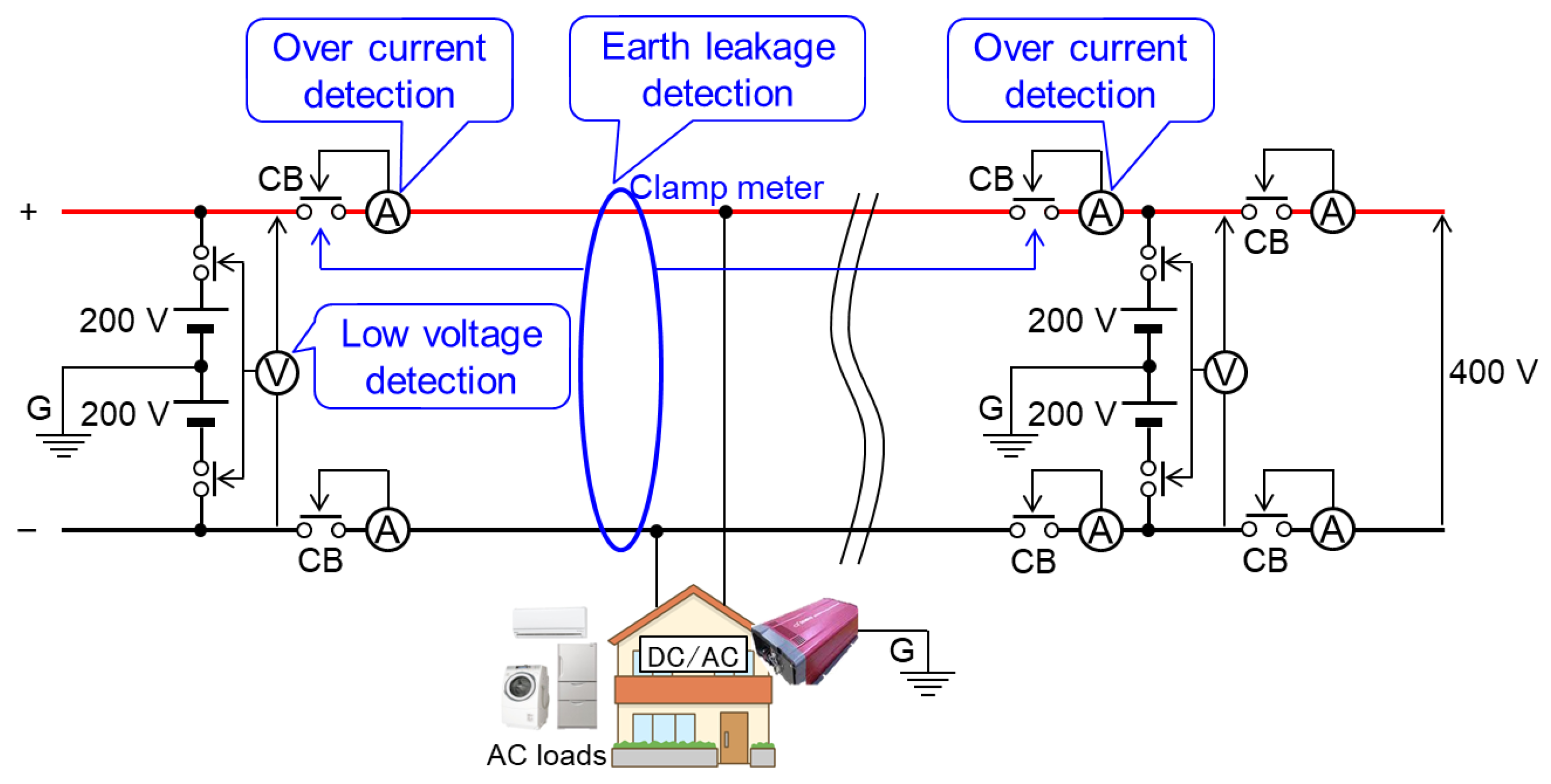
Figure 10.
Safety measures for microgrids.
9. Interconnection with Existing Power Grid
In microgrids that rely primarily on unstable renewable energy power generation, stable power supply remains a significant challenge. Conversely, existing power grid systems are vulnerable to natural disasters and face destabilization issues as the integration of renewable energy progresses. By interconnecting with existing power grid systems, we aim to cover the shortcomings of both systems, achieving a green, resilient, and stable power supply.
Figure 11 illustrates the method of interconnection between both grids. Within distributed regional microgrids, the goal is to utilize locally generated renewable energy, such as small-scale solar, wind, and hydroelectric power, to the fullest extent, while maintaining power supply through the provision of engine-driven emergency power sources in case of power shortages. However, equipping each microgrid with its own emergency power source is not efficient. By interconnecting with existing power grid systems, power can be received from the grid during shortages. Therefore, while each microgrid aims for partial optimization of power distribution through ADCC, the existing power grid system aims for overall optimization by equalizing power distribution among microgrids. This division of roles leverages the strengths of both microgrids and existing power grid systems. In this case, short-term and small-scale power fluctuations are addressed by the electrical inertia within each microgrid (momentary response), while long-term and large-scale fluctuations are addressed by power supply from the grid (sustained response).
Interconnection with the existing power grid also enables power exchange between microgrids. If renewable energy generation within a microgrid exceeds consumption and storage batteries become fully charged, off-grid systems would have to halt power generation. However, with interconnection, surplus power can be fed back into the grid and utilized by microgrids experiencing power shortages, thereby effectively utilizing the renewable energy potential without waste. Utilizing the existing power grid allows for wide-area power exchange, and realizing overall optimization of power distribution.
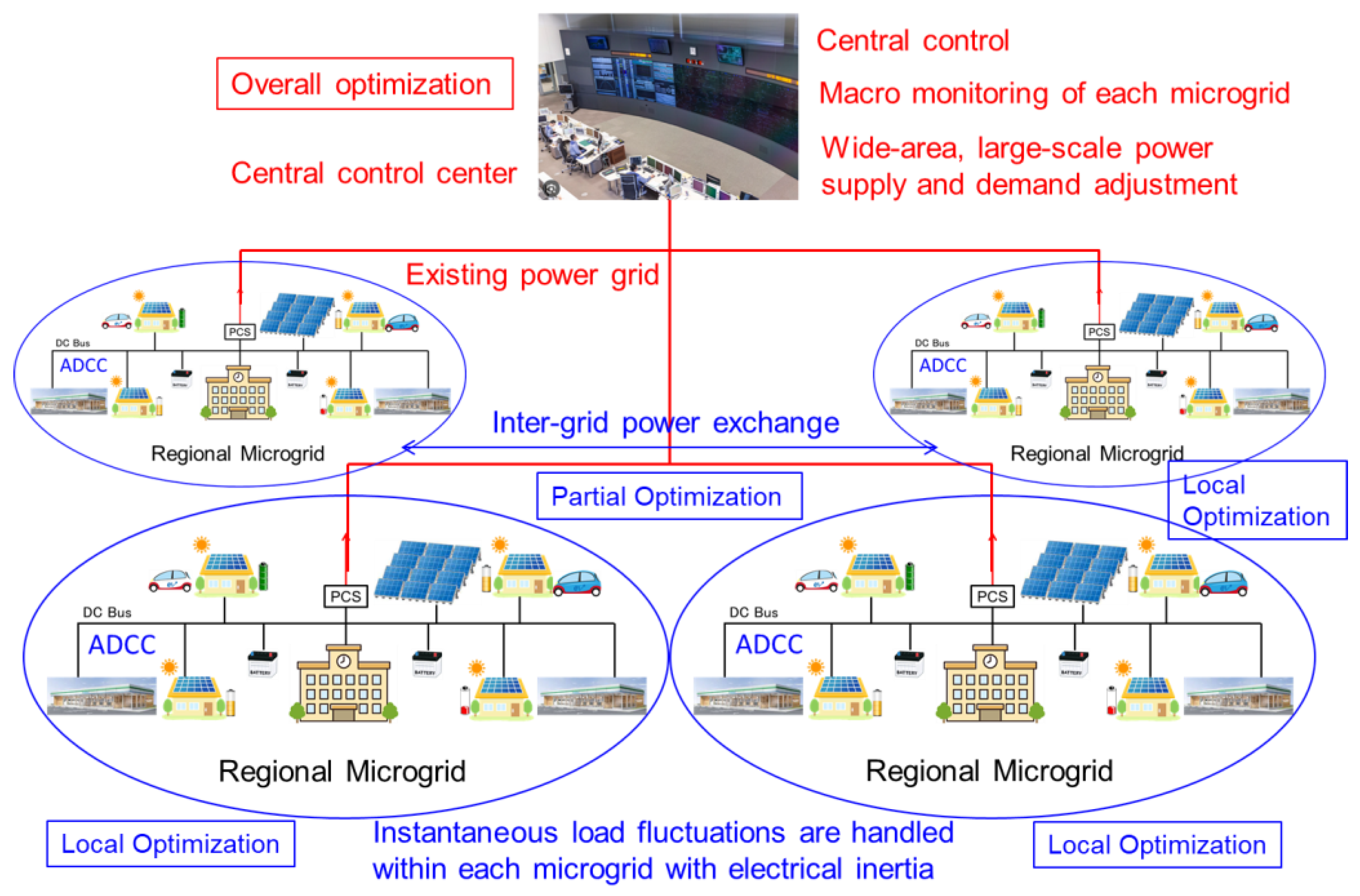
Figure 11.
Interconnection with existing power grid.
10. Conclusions
We propose a method of constructing DC microgrid by connecting small batteries distributed to the baseline achieves ADCC through the cooperative operation due to the Droop characteristics inherent in the batteries themselves and the control locality due to the weakly-coupled grid configuration. Moreover, by directly connecting the batteries to the baseline, a large electrical inertia can be distributed throughout the entire baseline, leading to grid stabilization. Additionally, the SoC of each battery within the grid is spontaneously equalized. This method is simpler compared to methods that use DC/DC converters and offers greater flexibility and scalability, making it a promising approach for realizing a DC microgrid with ADCC.
The implementation of DC microgrids is particularly necessary in residential areas. In countries like Japan, which are prone to natural disasters, the robustness of the power grid as a lifeline, alongside gas and water, is essential. ADCC DC microgrids can maintain functionality to some extent even if the baseline is disrupted. Each household, equipped with small batteries and weakly interconnected with each other by DC baselines, can share power generated from solar panels with neighboring households. This model of DC microgrids represents a new form of power infrastructure that we should aim for in the future.
Funding
This research was funded by JST OPERA Prog. (Grant Number JPMJOP1852). funding.
Acknowledgments
The author would like to extend special thanks to Ms. Liu Ke, who was a doctoral student in the author’s laboratory. Part of the content of this paper is based on the research conducted as part of her thesis under the guidance of the author. Additionally, through the JST OPERA project, the author had many valuable discussions with Professors K. Iwatsuki and T. Otsuji. The author would like to express deep gratitude once again.
Conflicts of Interest
The author declares no conflicts of interest. The funders had no role in the design of the study; in the collection, analyses, or interpretation of data; in the writing of the manuscript; or in the decision to publish the results.
Abbreviations
The following abbreviations are used in this manuscript:
| AC | alternative current |
| ADCC | autonomous decentralized cooperative control |
| BMS | battery management system |
| CB | circuit breaker |
| CO2 | carbon dioxide |
| CV | Cross-linked Polyethylene insulation Vinyl sheath |
| DC | direct current |
| EMP | electromagnetic pulse |
| EV | electric vehicle |
| LAN | local area network |
| MPPT | maximum power-point tracking |
| PC | personal computer |
| PV | photo voltaic (solar cell) |
| RCD | residual current devices |
| SoC | state of charge for batteries |
| SQ | square meters |
| USB | universal serial buss |
References
- Sun, K.; Zhang, L.; Xing, Y.; Guerrero, J.M. A Distributed Control Strategy Based on DC Bus Signaling for Modular Photovoltaic Generation Systems With Battery Energy Storage. IEEE TRANSACTIONS ON POWER ELECTRONICS 2011, 26, 3032–3045. [Google Scholar] [CrossRef]
- Cañizares, C.A.; Palma-Behnke, R.; Olivares, D.E.; Mehrizi-Sani, A.; Etemadi, A.H.; Iravani, R.; Kazerani, M.; Hajimiragha, A.H.; Gomis-Bellmunt, O.; Saeedifard, M.; Palma-Behnke, R.; Jiménez-Estévez, G.A.; Hatziargyriou, N.D. Trends in Microgrid Control. IEEE TRANSACTIONS ON SMART GRID 5, 1905–1919. [CrossRef]
- Kuma, J.; Agarwal, A.; Agarwal, V. A review on overall control of DC microgrids. Journal of Energy Storage 2019, 21, 113–138. [Google Scholar] [CrossRef]
- Al-Ismail, F.S. DC Microgrid Planning, Operation, and Control: A Comprehensive Review. IEEE Access 2021, 9, 36454–36172. [Google Scholar] [CrossRef]
- Uddin, M.; Mo, H.; Dong, D.; Elsawah, S.; Zhu, J.; Guerrero, J.M. Microgrids: A review, outstanding issue and future trends. Energy Storage Reviews 2023, 49, 101127. [Google Scholar] [CrossRef]
- Marnay, C.; Xu, T.; Hatziargyriou, N.D.; Hirase, Y.; Mendoza-Araya, P. Microgrids 2023 editorial. Applied Energy 2023, 352, 121981. [Google Scholar] [CrossRef]
- Rangarajan, S.S.; Raman, R.; Singh, A.; Shiva, C.K.; Kumar, R. , Sadhu, P.K.; Collins, E.R.; Senjyu, T. DC Microgrids: A Propitious Smart Grid Paradigm for Smart Cities. Smart Cities 2023, 6, 1690–1718. [Google Scholar] [CrossRef]
- Liu, K.; Yamada, H.; Iwatsuki, K.; Otsuji, T. Experimental Verification and Simulation Analysis of a Battery Directly Connected DC-Microgrid System. International Journal of Electrical and Electronic Engineering & Telecommunications 2023, 12, 326–333. [Google Scholar] [CrossRef]
- Chowdhury, S.; Shaheed, M.N.B.; Sozer, Y. ; State-of-Charge Balancing Control for Modular Battery System With Output DC Bus Regulation. IEEE TRANSACTIONS ON TRANSPORTATION ELECTRIFICATION 2021, 7, 2181–2193. [Google Scholar] [CrossRef]
Figure 1.
Control methods of power grids, (a) Centralized control method; (b) Autonomous decentralized cooperative control (ADCC) method.
Figure 1.
Control methods of power grids, (a) Centralized control method; (b) Autonomous decentralized cooperative control (ADCC) method.
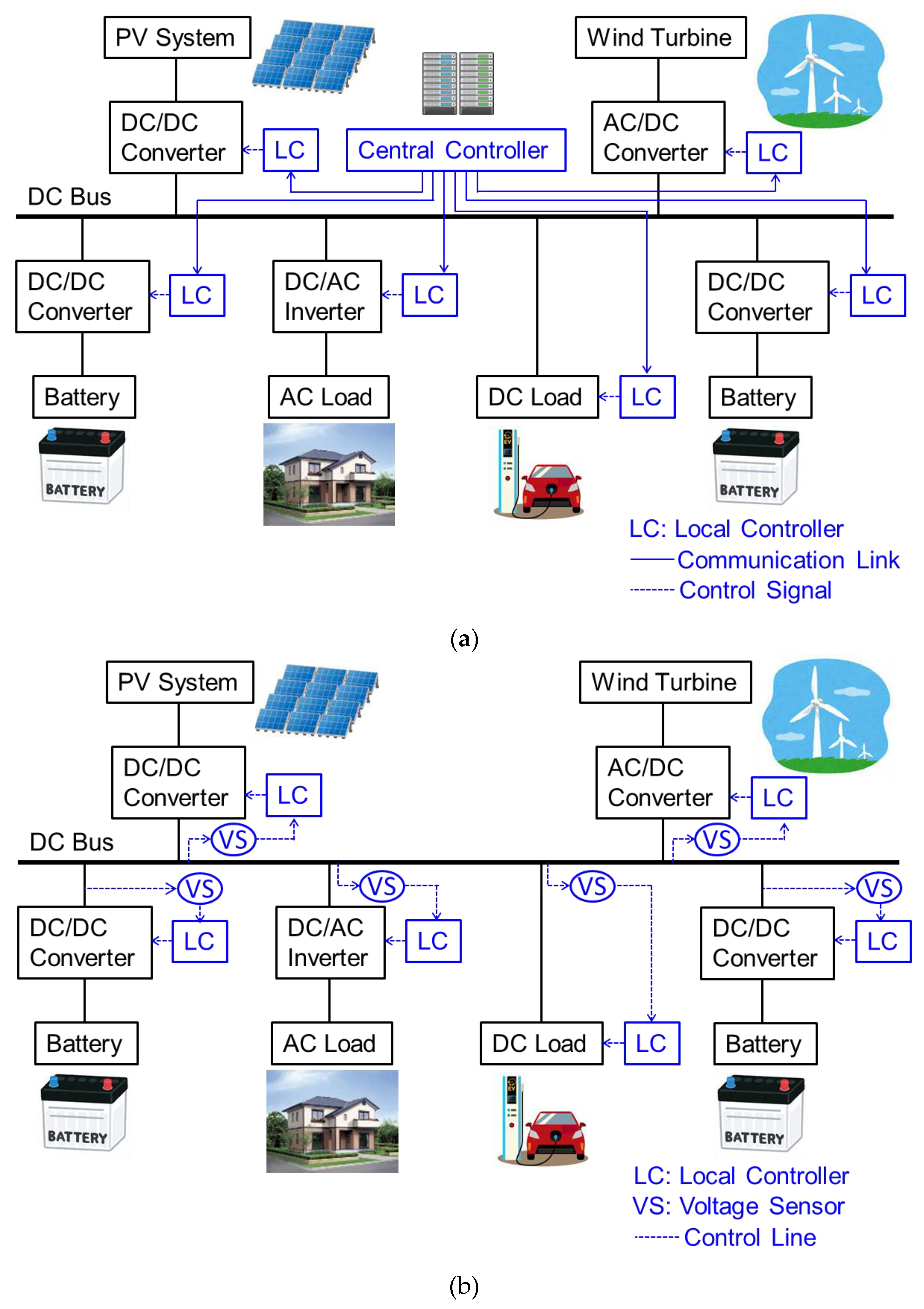
Figure 2.
Droop characteristics of a battery, (a) Basic equivalent circuit of a battery; (b) The relationship between the load rate α and the terminal voltage Vt.
Figure 2.
Droop characteristics of a battery, (a) Basic equivalent circuit of a battery; (b) The relationship between the load rate α and the terminal voltage Vt.
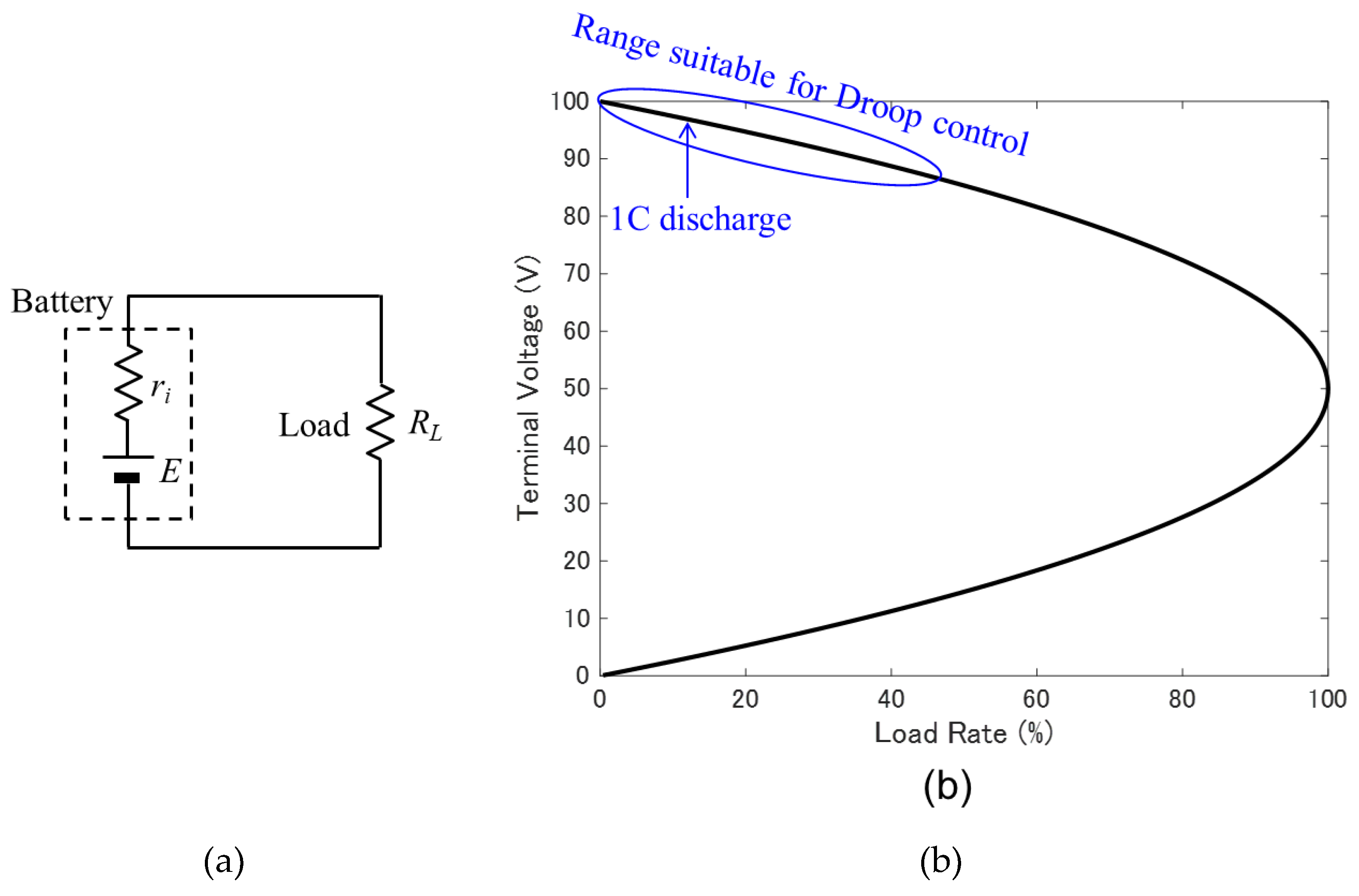
Figure 3.
Calculation of electrical inertia for number of battery divisions N, (a) Divided battery placement on the baseline; (b) Calculated electrical inertia on the baseline.
Figure 3.
Calculation of electrical inertia for number of battery divisions N, (a) Divided battery placement on the baseline; (b) Calculated electrical inertia on the baseline.
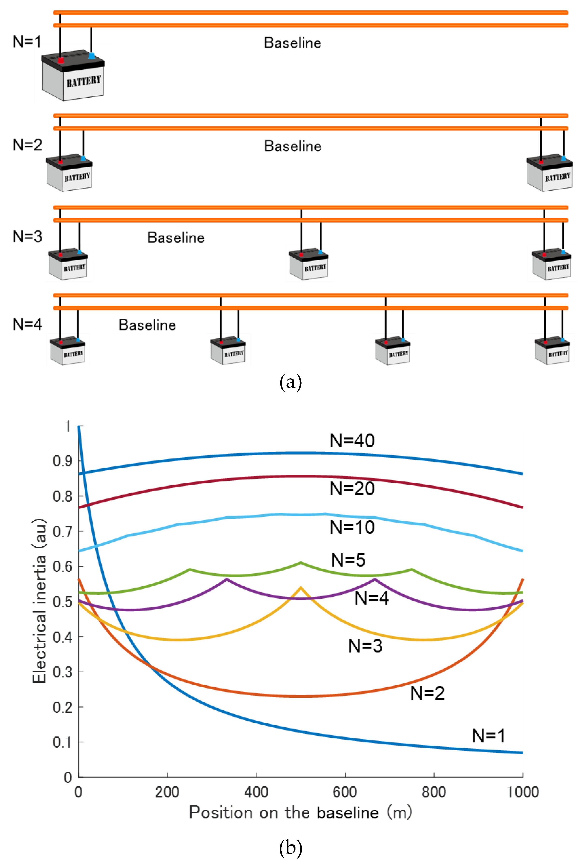
Figure 4.
Locality of MPPT charging control with weakly coupled grids.
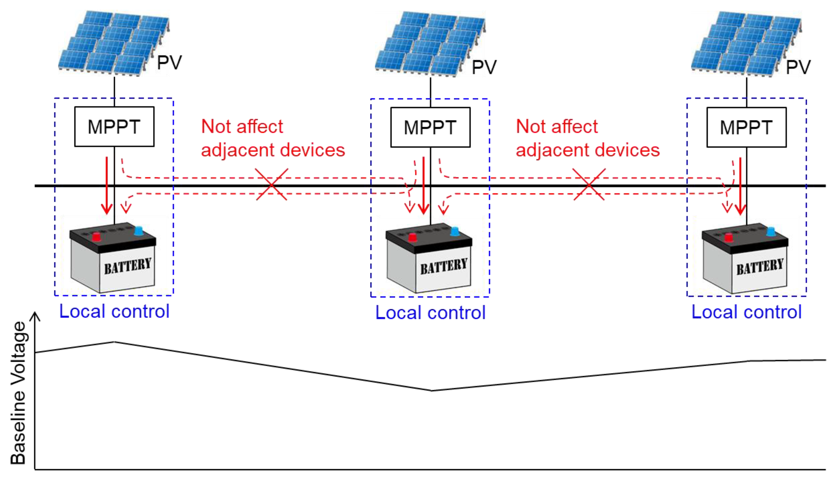
Figure 5.
Frequency transmission characteristics of a CV.
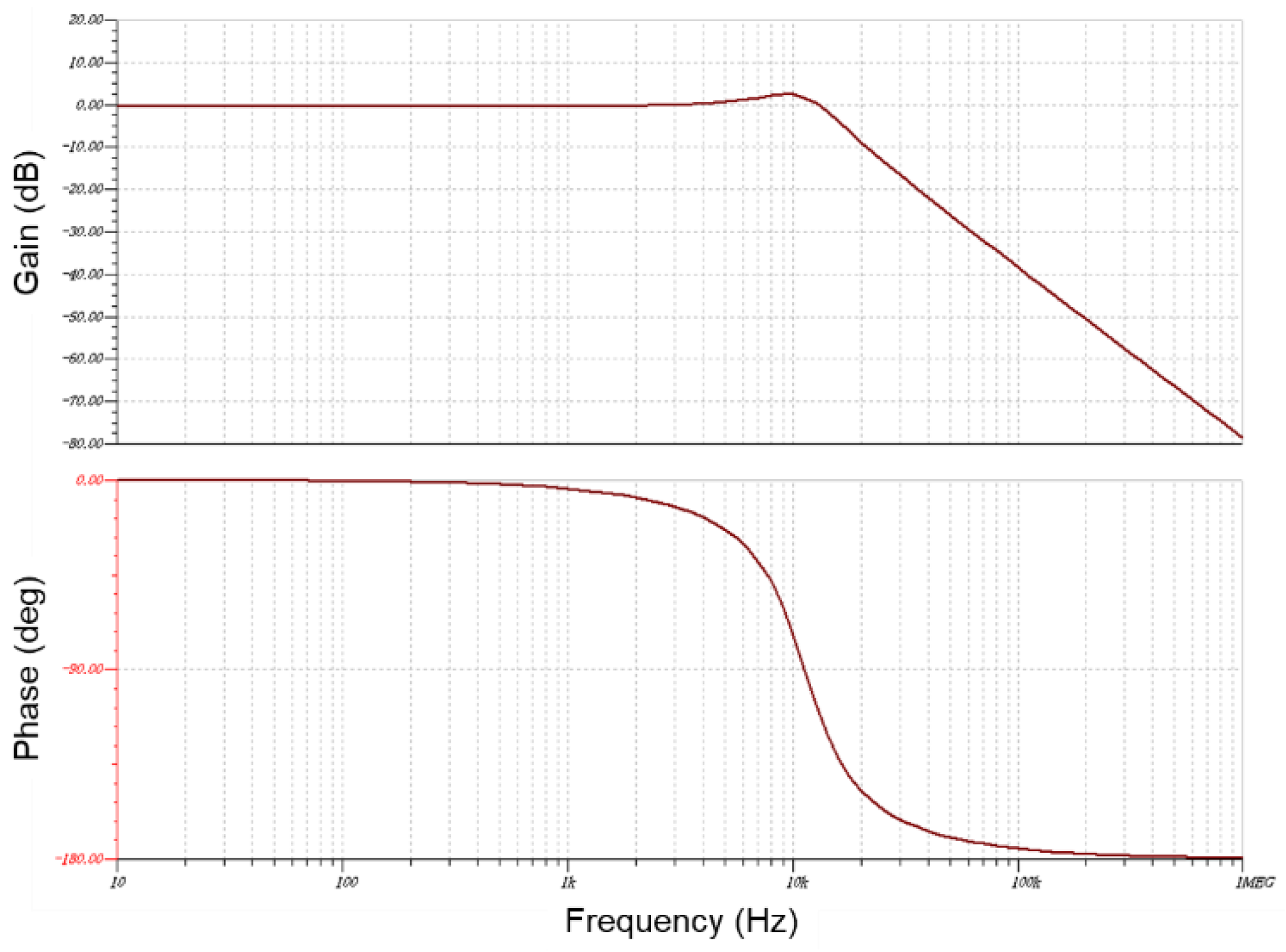
Figure 6.
Experimental demonstration of the DC microgrids.
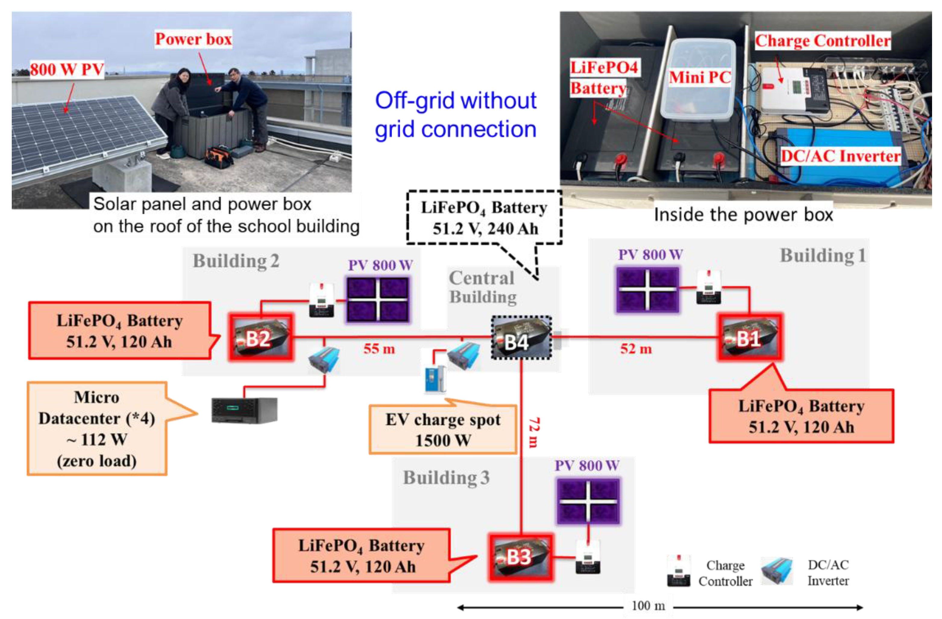
Figure 7.
Monitor screen of the microgrid operation.
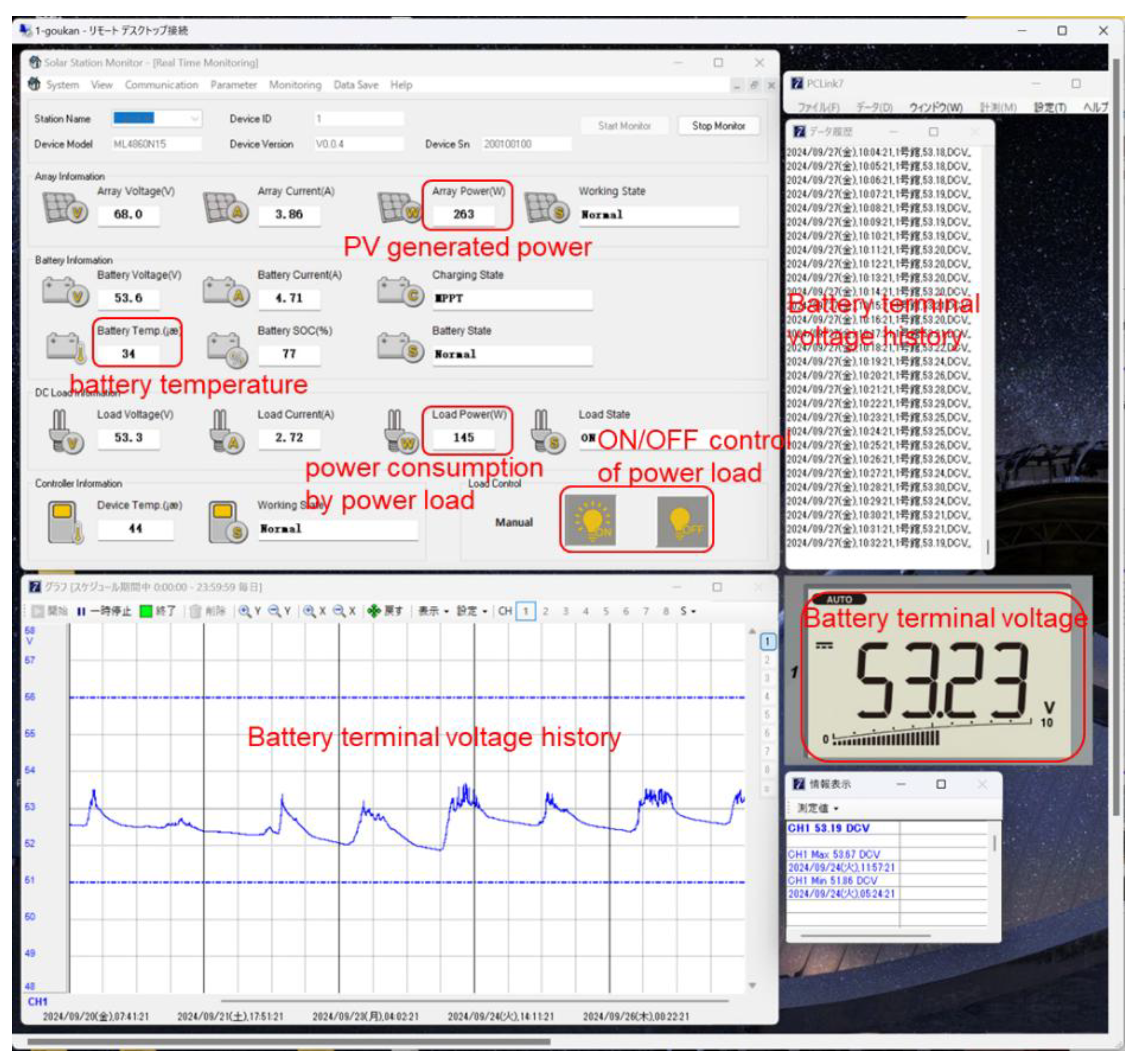

Table 1.
The specifications of the constructed DC microgrid.
| Battery | Solar panel | DC/AC inverter | Monitoring | |
|---|---|---|---|---|
| Building 1 | LiFePO4 51.2 V, 60 Ah × 2 |
800 W | 100 V, 3 kW for EV chaging |
Battery voltage Battery temperature Charging current PV power generation |
| Building 2 | LiFePO4 51.2 V, 60 Ah × 2 |
800 W | 100 V, 1.5 kW | Battery voltage Battery temperature Charging current PV power generation |
| Building 3 | LiFePO4 51.2 V, 60 Ah × 2 |
800 W | 100 V, 1.5 kW | Battery voltage Battery temperature Charging current PV power generation |
| Central Building | LiFePO4 51.2 V, 60 Ah × 4 |
− | 100 V, 3 kW for EV chaging |
Battery voltage Baseline current |
| Entire grid | LiFePO4 51.2 V, 600 Ah (~30 kWh) |
2.4 kW | − | Baseline voltage: 51~56 V |
Disclaimer/Publisher’s Note: The statements, opinions and data contained in all publications are solely those of the individual author(s) and contributor(s) and not of MDPI and/or the editor(s). MDPI and/or the editor(s) disclaim responsibility for any injury to people or property resulting from any ideas, methods, instructions or products referred to in the content. |
© 2025 by the authors. Licensee MDPI, Basel, Switzerland. This article is an open access article distributed under the terms and conditions of the Creative Commons Attribution (CC BY) license (http://creativecommons.org/licenses/by/4.0/).
Copyright: This open access article is published under a Creative Commons CC BY 4.0 license, which permit the free download, distribution, and reuse, provided that the author and preprint are cited in any reuse.


