
Submitted:
11 March 2025
Posted:
12 March 2025
You are already at the latest version
Abstract
This is part II (of the two-parts paper) dedicated to the development of a pre-rationalization approach that provides favorable constructive properties for the low-tech construction of doubly curved structures. In this second part, we utilize the geometric constructs developed in part I, specifically patches with one direction of their coordinate curves being planar (PU-property) and the other direction generating developable strips (V-strips), to address site constraints. More precisely, we articulate a design process based on these constructs that allows for the low-tech construction of a doubly curved bamboo structure without falsework.
Keywords:
Bamboo structures
; Low-tech fabrication
; Falsework-free construction
; Traditional techniques
; Design for assembly and disassembly
; Planar coordinate curves
; Architectural Geometry
1. Introduction
The exploration of sustainable building materials and methods has gained significant attention in the field of architecture, particularly with the increasing emphasis on environmentally friendly and resource-efficient construction. This paper, the second part of a two-part series, delves into the practical application of bamboo in constructing doubly curved surfaces without the use of falsework. The focus of this study is the construction of a bamboo structure titled "La Fleur Mathématique", which was erected in the historic Pillnitz in Dresden, Germany.
This was part of the "Plant Fever" exhibition organized by the The arts and crafts museum. Building on the geometric constructs and design models developed in part I, this paper applies these methodologies to address specific project requirements and site constraints. The design principle uses a pre-rationalization process where the defined geometric properties directly inform the necessary fabrication strategies. After establishing these, the form was created by finding the organic motif of an unfolding leaf in the Dini surface. The Dini surface has the necessary geometric properties, and it establishes the connection between mathematics and architecture.
Figure 1.
The realized bamboo structure.
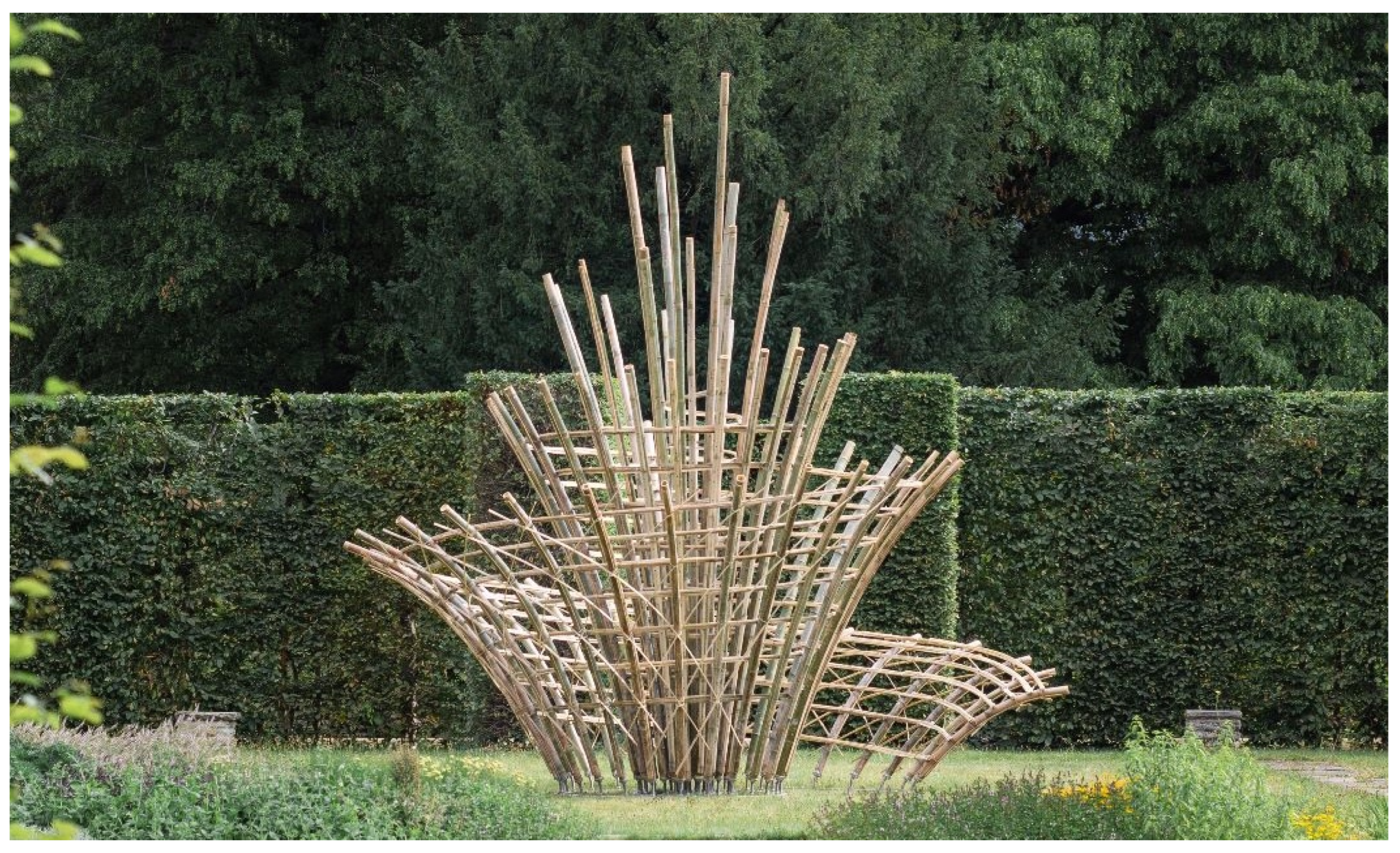
The central innovation lies in the pre-rationalization approach, which employs parameterized traditional bending techniques to facilitate the construction of complex forms using bamboo. The structure was designed and constructed with the principles of low-tech fabrication, emphasizing simplicity, efficiency, and sustainability. The project was realized in seven days with the help of 20 participants within the framework of the “Architectural Mathematics for Bamboo Structures (AMBS)” summer school, organized by the Geometric Modelling and Visualization (GMV) research group at TU Dresden, Germany. The structure was disassembled and moved to TU Dresden’s botanical garden, where it was reassembled, highlighting the re-assemblability potential of this process. This bamboo structure is the first contemporary structure to be erected and displayed amidst the Pillnitz Park, whose origins date back to the 17th century. Negotiating the interests and safety precautions of various institutions presented several challenges that required unique solutions. Since the form had to be assembled in a short period, the elements were prefabricated before being transported to the site. Section 2 of the paper details the design and fabrication methods, integrating contextual, historical, technical, and logistical considerations.
It highlights the form generation method based on the geometric constructs explained in part I and discusses bamboo as a building material and the chosen traditional fabrication techniques for realizing curved structures. Next, Section 3 outlines the realization approach, broken down into three project phases. The first phase involves the prefabrication of the five main structural elements (primary structure, secondary structure, foundation, bracing, and cladding) using parameterized versions of traditional bamboo construction techniques. The second phase describes the falsework-free assembly process, detailing the sequential on-site assembly of prefabricated components. This approach reduced environmental impact and demonstrated the efficient construction of complex bamboo structures, ensuring stability through the alternating assembly of primary and secondary structures. The third phase covers the disassembly and reassembly technique used to relocate the structure with minimal impact on the materials and the environment, highlighting its reusability and adaptability. This experimental approach allowed the structure to be relocated from Pillnitz to the botanical garden of TU Dresden. Finally, Section 4 concludes with a summary of the findings and the broader implications for sustainable construction practices.
2. Project Development
The design and fabrication methods of the structure result from integrating contextual, historical, technical, and logistical considerations. Given the diverse nature of these considerations, they had to be addressed at different points (phases) of the design process. Table 1 provides a few examples of how these considerations impacted the design, fabrication, and construction of the structure.
As outlined in Table 1, the initial consideration was the theme of the Plant Fever exhibition at the Pillnitz Park near Dresden. Our goal was to reflect this theme by achieving a floral aesthetic (cf. SubSection 2.1) using sustainable, natural building materials like bamboo. Site-specific factors included limited accessibility through four narrow passages, each wide, and the park’s historical significance, which prohibited the use of large transport vehicles, limited working hours, and restricted invasive foundations. These constraints, along with the prohibition of cranes, falsework, and external scaffolding, led us to prefabricate lightweight structural elements that could be manually carried and installed by a maximum of two people. Given these challenges, we implemented traditional low-tech bamboo fabrication techniques and emphasized a falsework-free assembly approach. This method involved anchoring the primary structure to the ground with a steel base to withstand wind loads, creating a stable platform for assembling the remaining components. Combining low-tech fabrication with falsework-free assembly posed significant design and logistical challenges, requiring extensive interdisciplinary collaboration. To address these challenges, we employed the pre-rationalization approach from Part I, aligning fabrication and assembly requirements with specific geometric properties derived from surface and patch choices. This approach reformulated these requirements geometrically, allowing solutions to be generalized into methods rather than one-offs. For instance, the Rup-rup bending technique was geometrically parameterized (cf. Section 3), offering a method of tracing both planar and spatial curves. below, we explain two main aspects of the project’s development: the form generation and the chosen bamboo fabrication techniques adapted to our doubly curved structure.
2.1. Form Generation
The formal resemblance of the Dini surface to a blossom or an unfolding leaf, illustrated in Figure 2 allows the emphasis of the theme of "nature-inspired art forms". Rather than imitating natural forms Art nouveau manner, the design process begins with the mathematical Dini surface described through the following explicit expression, given in part I.
In Figure 2, we can see that by manipulating the surface’s domains and parameters, we start getting variations of the Dini surface that, through refining, increasingly resemble the unfolding of a leaf. Moreover, we can see how those variables were set to obtain the desired shape that rolls about itself while ascending, which, through its composition and the spiral-like ridge, emulates petals. This shape is then trimmed by a spatial spiral curve and a horizontal plane (ground) to respectively further enhance the floral shape of the structure and create a plane on which the foundations could be installed. Finally, the network curves of both patches were used to generate the structural components. The principal patch generating the primary and secondary structures as well as the cladding. The asymptotic patch generating the bracing elements that bisect the main structural elements at the same intersecting points. Approaching the design in this manner achieves aesthetics.
But also yields essential constructive properties necessary for its rationalization as a coherent structure and for the fabrication of its structural components. These constructive properties are explained in detail in SubSection 3.1. In the intorduction of part I, we can see the translation of the geometric properties into constructive ones. The use of the principal curvature lines as the parameterization of the Dini surface allows one direction of its coordinate curves (the u direction) to be planar, categorizing it as a “PU-patch”. Meanwhile, the v direction generates developable cladding strips (V-strip) through the joins of two neighboring v-curves, which can be unrolled without distortion on the ground. These two directions of curves translate into the primary and secondary structural components of the structure. The primary structure is realized using whole bamboo poles bent with a parameterized version of the traditional Rup-rup technique, which is mainly adapted to planar curves, as explained in Section 3.
The secondary structure is realized using Lidi-bundles of bamboo splits, which are more suited to spatial curves, as detailed in Section 3. Additionally, the V-strips serve as cladding components that are fabricated flat and then elastically curved on the structure, as described in Section 3. Furthermore, as demonstrated by [1], it is possible to achieve a correspondence of principal and asymptotic networks on surfaces with negative constant Gaussian curvature, such as the Dini surface. This feature is significant for our structure because it means that there are two directions of curves that bisect the principal directions diagonally and intersect each other orthogonally at the same points where the principal directions intersect. These asymptotic curves, being in the diagonal directions to the primary and secondary structures, allow for the construction of strips using straight bamboo splits, as their base asymptotic curves have zero normal curvature [2], as shown in the Introduction of part I and explained in Section 3. The translation from geometric to constructive properties further demonstrates the viability of the pre-rationalization approach, as it allows for the integration of these constructive properties from the onset of the design process, making the approach adaptable to changes occurring at later stages of the project.
3. Realization Approach
Aspects of the realization of the structure can be divided into two parts:
- Rationalization and fabrication of the structural components: Application of traditional fabrication methods based on the constructive properties provided by the pre-rationalization mathematical surface.
- Falsework-free assembly of the structural components: On-site sequential assembly of the pre-fabricated structural components without the use of falsework.
3.1. Fabrication of Structural Components
The bamboo structure comprises five structural components, as illustrated in Figure 3. These components were fabricated using traditional techniques, which were parameterized and/or reinterpreted to simplify the fabrication process while optimizing precision and fabrication time, as explained in detail in the following Sections.
• Component 1: Primary structure → Rup-rup poles The traditional Rup-rup technique involves making V-shaped cuts (spanning of the pole’s width) at specific intervals along its length (in the internodes) [3,10]. The resulting pole will follow the desired curvature once pressure is applied to its extremities until the sides of each cut meet. To note that although increasing the number of cuts will better approximate the curved pole to the target network curve, it also increases the pole’s structural fragility. While this technique exists, using it to transform a straight bamboo pole into one that corresponds precisely to a desired curve is more challenging. This is because accurately determining the positions and angles of the cuts requires a mathematical reformulation of the problem. This reformulation involves inferring global properties (the overall curved shape of the bent bamboo pole) from local properties, such as changes in curvature and torsion at specific points. The mathematical reformulation of this technique varies depending on the nature of the network curve. In the following Section, we demonstrate how this is achieved planar curves (used in the realization of the structure).
The problem in 2-dimensions is relatively simpler since the planar curve C contains no torsion. It then follows that the shape of the curve C is determined by how it curves in the plane, as explained below. Let be a list of discrete points on the planar curve, with the length of the piece of curve . Next, let be the tangent vectors at the points , with the angle between , also known as the turning angle, as shown in Figure 4 (right). We will also refer to the turning angle as the (average) curvature angle, since the actual (signed) curvature of C at is:
Now, to carry out the (local) geometric method of bending the straight pole, we need to collect two further lists of lengths: and . These are the lengths of the segments between points and points , where each point is obtained by intersecting the line with the line , as seen in Figure 4.
Next, observe that the length of the straight pole before bending should be equal to the sum of the lengths of and , not the arc length of the planar curve C. Of course, these two lengths will converge as we add more and more discrete points.
In view of the above, we are now able to start with a straight bamboo pole and bend it into the desired shape using only local knowledge at the points. This local geometric bending method is as follows: we start by collecting the data list:
Next, we mark the appropriate lengths and on the straight bamboo pole, and finally use the angles to create V-shaped cuts in the pole. By simply bending the pole to close these cuts, we obtain the desired curved shape, as shown in Figure 5.
While the cut bamboo pole traces the planar network curve up to a certain approximation, it doesn’t remain in its bent shape due to elastic properties. Various methods to address this issue have been demonstrated [3], such as bundling several poles together to enhance structural stability through reciprocal support at the v-cut spots. However, due to project constraints, including the weight of each individual structural components, our chosen method involves screwing a longitudinal bamboo split (a segment of the pole) to the bent pole along the side with the cuts, as illustrated in Figure 6.
It is important to mention that the choice of the positions (not only the number) of the discrete points (V-shaped cuts) plays a crucial role in approximating the curve C with segments. Even with the same number of points, placing them closer together in high curvature zones than in low curvature zones allows for a better approximation. Thus, using a non-uniform distribution of points helps achieve a more accurate result with the same number of points, while also avoiding further weakening of the cut bamboo pole. In Figure 7, we illustrate the technique used to extract longitudinal splits (as shown in Figure 6) from the whole bamboo pole [4]. This technique begins with using a bamboo splitter to divide the entire pole into equally sized segments. Subsequently, any remaining parts of the nodes attached to these splits are removed using a chisel to achieve a flush inner wall. This step is crucial as it facilitates easier bending and fitting of the splits over another pole. Attaching the split to the cut pole serves two purposes: it maintains the bent shape of the pole and adds structural stiffness by compensating for some of the lost material. Additionally, it introduces a layer of continuous longitudinal fibers that provide tension resistance when loads are applied to the component, as illustrated in Figure 8.
• Component 2: Secondary structure → Lidi-bundles The second component is the secondary structure made out of Lidi-bundles. A Lidi-bundles, as described in [10], consists of "thin" longitudinal bamboo splits lashed together along their lengths. As depicted in Figure 9, the number of splits in a Lidi-bundles is directly proportional to the radii of curvature at discrete points along the spatial curve. Consequently, the spatial curve is segmented into sections where the number of splits in each bundle corresponds to the bending capacity required for the average radius of curvature in that section.
It’s important to note that while there is a logical relationship between the radius of curvature and the number of splits, the exact values are empirical and depend on factors such as the bamboo species, treatment methods, the width of the splits, etc. As seen earlier in Figure 7, curved bamboo splits can be obtained from a pole using a bamboo splitter. However, there is a limit to how thin these splits can be made using this technique. To achieve bamboo splits with smaller widths, as shown in Figure 10, we employ a method where the curved splits obtained from the splitter are further divided into thinner ones with nearly square cross-sections. This is done using chisels inserted at various points along the length of the split to ensure the resulting "thin" splits have a consistent width throughout their length. Subsequently, these "thin" splits are joined together and lashed to create a bundle. The bundle is manually bent to follow the spatial curve, and additional lashings are added to secure the bundle in its curved shape. As seen in the Rup-rup case, there are structural considerations to take into account when designing the Lidi-bundle. It is true that the fewer the splits in a bundle, the more flexible it becomes, which is advantageous for tracing spatial curves of varying curvatures. However, this flexibility reduces its structural performance, especially in compression (buckling).
Naturally, the spacing between two intersection points (where the bundle is fixed) plays a crucial role in stiffening the structure, even with the same number of splits in the bundle. As depicted in Figure 11, smaller distances between fixed points result in less buckling, whereas larger distances lead to more significant buckling issues.
In the case of our bamboo structure, as illustrated in Figure 12, this was not a primary concern because as the bundle containing fewer splits approached the highest point of the spatial curve, the distances between the primary structural elements decreased incrementally. This arrangement provided a balanced structural stiffness and significantly reduced the buckling effect.
• Component 03: Foundation → Base + Pins Due to the particularities of the site and the ephemeral nature of the structure, designing the foundation had to address several concerns. These included potential damage to the grass, narrow access points, and most importantly, ensuring the overall stability of the structure. Initially, we considered creating a steel base to which all the bamboo poles could be fixed. The base would need to be sufficiently heavy to resist tilting without requiring additional anchoring. The rationale behind this was that the structure, being lightweight and inaccessible, would not experience significant deformation under its own weight. If the base could resist tilting under wind loads, it would eliminate the need for anchors. However, the ends of the primary structure form a spiral shape, which means the tilting axis is a straight line intersecting the endpoint of the spiral and tangent to the furthest point of curvature. The center of gravity is only slightly eccentric to the origin of the spiral. Additionally, the floral shape of the structure results in an extremely narrow base, with a distance from the tilting axis to the center of mass of 80 cm, as depicted in Figure 13. Ultimately, a stability test under wind loads was conducted, which involved determining:
- The total surface area of the structure subjected to wind loads was 8.5 m². This calculation was performed by projecting the profiles of the structure onto a vertical plane placed along the tilting axis.
- The wind loads were determined in accordance with DIN 1055-4:2005-03, considering that the structure is located in Pillnitz, which corresponds to wind zone 1.
Taking into account the wind loads according to DIN 1055-4:2005-03 for wind zone 1, with safety factors.
This resulted in a moment load of 6 kNm and indicated that relying solely on a steel base as a counterweight was not feasible. Therefore, the alternative choice was to anchor the structure to the ground. Cantilevering the base was ruled out for aesthetic reasons. As a result, the foundation was designed as follows:
The Base: The design of the base, as depicted in Figure 14, features a spiral-like stainless-steel sheet divided into nine partitions joined together by bolts. Eight partitions are approximately 100 cm long, 10 cm wide, and 2 cm thick, while the central partition measures approximately 70 cm long, 60 cm wide, and 2 cm thick. This spiral design follows the ends of the primary structure (Rup-rup poles)and reflects the filigree nature of the overall design. Anchor points are integrated into the base at the center and at five evenly spaced points. The partitions are designed for easy manual handling, simple installation, and transportation, as detailed in (Section 3.2). Once bolted together, the entire base is secured to the ground using six anchor rods, each 50 cm long and 4 cm in diameter. These anchors feature a spiral surface with a high pitch, allowing them to be hammered into the ground and unscrewed with minimal damage.
The anchors may appear oversized, but they are selected to meet regional codes assuming sandy soil conditions. They provide a pull-out resistance of 2.3 kN under challenging conditions, ensuring they can withstand the calculated moment load effectively.
The Pins: This component details the rigid connection that links the primary structure to the steel base, inspired by bamboo metal connectors pioneered by architect Simón Vélez and demonstrated in [5]. This connection involves affixing a metal pin or bar to one end of each bamboo pole, which is then securely bolted or screwed to the foundation. Figure 15 illustrates the initial steps in implementing this connection: firstly, the first node of the primary structure (as depicted in Figure 6: Step 07) is pierced using a metal bar, allowing for the insertion of a threaded pin ≈ 30 cm into the pole.
Subsequently, a hole is drilled into the pole’s wall ≈ 7 cm below the second node ([5,11]). It is noteworthy that due to the non-vertical orientation of the Rup-rup poles in relation to the base, and the impracticality of using a hinge connection due to kinematic constraints, a rigid connection approach was chosen. This involved bending 70 threaded rods to 70 unique angles to ensure secure attachment to the foundation. In Figure 16, the process continues by capping the end of the pole with a metal cup (a pierced clinker base used for sealing metal pipes), which is secured to the threaded pin using a washer and bolt to ensure a tight seal. Through the drilled hole, using a funnel, mortar (details of its properties below) is poured into the cavity (the first two internodes) until it fills completely. This process securely attaches the threaded pin to the pole while preventing the pin from pressing against the wall and potentially causing fractures under load.
As mentioned earlier, mortar was utilized to fill the cavity between the pin and the pole wall. Table 2 outlines the composition of the mortar developed for this purpose. An accelerator was incorporated into the mixture to expedite the hardening process, and particles with a maximum size of 1 mm were used due to the dimensions of the drilled hole. The objective was to prepare a mixture that is sufficiently liquid to be poured easily, yet capable of setting quickly to accommodate the project’s tight schedule. The mortar was prepared in batches of 5 liters using a Hobart SHM30 mixer. Initially, the dry components were mixed for 3 minutes at the first speed (approximately 68 rpm). Subsequently, water containing an accelerator was added and mixed at the same speed for an additional 1 minute.
Afterward, superplasticizer was introduced, and the mixture was agitated at a higher speed (approximately 178 rpm) for 4 minutes.
It’s noteworthy that the compressive strength of the mortar was later tested after 28 days using 40 mm cubes, yielding an average value of 101 MPa. Once the mortar had set, the two components (base + threaded pins) were secured together using washers and bolts, as depicted in Figure 17. This method ensures a robust connection that withstands structural loads while maintaining the integrity of the bamboo pole and its anchored base.
• Component 4: Bracing → Bamboo splits Note that, the structure is braced using "thin" longitudinal bamboo splits, as demonstrated in Figure 10 (Step 02). These splits trace specific network curves originating from the asymptotic patch that bisects both the primary and secondary structures, as highlighted by [1,2].
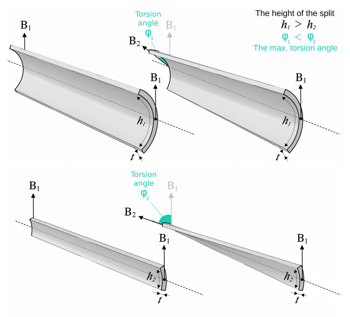
It is important to note that while a bamboo split tracing an asymptotic curve may exhibit slight curvature, its significant characteristic is the torsion angle or twist angle . Mechanically, denotes the rotation of the profile or cross-section about its longitudinal axis. Geometrically, it represents the angle between the binormal vector at point and the binormal vector at point in the plane perpendicular to the tangent vector .
We have three main structural factors: cross-section of the split, distance between intersection points, and number of splits. In the case of bracing with individual splits, our primary concern was the correlation between the cross-section h and twisting capacity .
Figure 19.
Relation between height and twisting.
3.2. Falsework-Free Construction
Falsework serves as a temporary support structure that holds discrete structural components in place until they are joined together and the structure becomes stable [9]. While the vast majority of constructions require some form of temporary support during assembly, conventional falsework methods for complex or non-standard constructions are often costly, generate significant waste, and rely heavily on digital fabrication facilities [6,7]. Although there have been explorations into bending-active or reusable falseworks, these approaches remain experimental and are typically limited to certain types of doubly curved shapes [6] and some recent work on construction Without Formwork by [8]. To address these challenges and considering project constraints outlined in Table 1, we have pursued a falsework-free construction approach. This method utilizes the prefabricated primary structure (as depicted in Section 3) as a foundational support for assembling other structural components that require active bending, such as the secondary structure and bracing elements. By adopting this strategy, we circumvent the complexities associated with conventional falsework, including high costs and installation challenges.
• Layout of the structural components: In Figure 20, we can see a layout of the prefabricated structural components, including the steel base with its anchors, the bracing splits divided into two sets, the Rup-rup poles with steel pins attached, the Lidi-bundles of splits, and wooden beams.
• Sequence of assembly without falsework:
The decision to opt for on-site assembly of prefabricated structural components without falsework was motivated by several factors, some of which were highlighted in Table 1, particularly those linked to the nature of the construction site. The sequential, falsework-free assembly of prefabricated structural components proceeded as follows:
Step 1. First, we begin by placing the partitions of the steel base (unbolted) in their correct positions on the ground to mark the locations of the 6 anchors, as depicted in Figure 21 (left). Once this is completed, the partitions of the steel base are removed, and the anchors are inserted into the ground, as shown in Figure 21 (right).
Step 2. Next, we reassemble the steel base, which consists of 9 partitions, over 5 wooden beams as illustrated in Figure 22. The wooden beams create enough space underneath the steel base to allow access for bolting its partitions together and later assembling the primary structure onto the base. This ’shallow’ foundation with a small footprint was chosen to comply with site restrictions, being less invasive and not damaging to the grass. Dividing the base into parts facilitates easy transportation by stacking them, handling through narrow pathways, and installation without heavy machinery.
Step 3. Following that, we install the first batch of 6 Rup-rup poles (primary structure) onto the base. First, we align them according to the markings made on both the base and the poles beforehand. Then, the poles are securely fastened in place using bolts, accessible via the space underneath the elevated steel base, as depicted in Figure 23. Due to their rigidity, the Rup-rup poles are easy to install without rebounding. They also serve as a form of falsework or guide for tracing the secondary structure.
Step 4. Once the first batch of the rigid Rup-rup poles is securely installed, we begin elastically bending the Lidi-bundles of splits one by one into position against the Rup-rup poles, following the earlier markings. We then screw them sequentially onto the poles, starting from the innermost pole outwards, as shown in Figure 24. Due to the Dini’s particular shape that narrows towards the center, we alternate between bolting batches of the Rup-rup poles to the base and screwing the Lidi-bundles onto them. This alternating process is repeated until all components of the primary and secondary structures are assembled.
Step 5. Having assembled the primary and secondary structures (Rup-rup poles and Lidi-bundles of splits respectively), both sets of the bracing elements made from individual bamboo splits.
These are elastically bent to trace diagonally and bisect the orthogonal intersections between the primary and secondary structures (as explained in SubSection 2.1). Once in place, the bracing elements are tied to the structure at those intersection points using traditional lashing knots (courtesy of artist Masayo Ave), as shown in Figure 25. These lashing knots ensure a secure and stable connection, enhancing the structural integrity of the assembly, and contributing to the aesthetic appeal of the design.
Step 6. Finally, the wooden beams beneath the steel base are gradually pulled out, lowering the base until it rests securely on the ground ensuring precise alignment and stability. Once the base is in its designated position, the structure is fastened in place using bolts, securing it to the anchors previously inserted into the ground, as depicted in Figure 26.
4. Conclusion
This paper demonstrated the innovative application of a pre-rationalization approach using a variant of the Dini surface patch with planar network curves (PU-patches) for the falsework-free construction of a bamboo structure. This approach translated geometric properties into constructive elements, addressing site-specific considerations from the initial design stages. It also shows how reformulating traditional bamboo construction techniques preserved their low-tech essence and cost-effectiveness while enabling the construction of predetermined complex forms. Hands-on construction and relocation validates the method’s sustainability, minimizing waste and environmental impact. Documenting the entire process helped present a comprehensive pre-rationalization approach for the falsework-free construction of doubly curved bamboo structures. This method enhances construction efficiency and models sustainable building practices. Looking forward, we anticipate broader applications of the pre-rationalization approach to various bamboo structures, the formulation of the Rup-rup technique for 3d curves, and expansion of the falsework-free construction to other PU-patches.
Acknowledgments
The research of the author Tošić, Z. is part of the priority program SPP 2187 and funded by the German Research Foundation (DFG) and the research of the author Elshafei, A. was partially financed by Portuguese Funds through FCT (Fundação para a Ciência e a Tecnologia) within the Project UIDB/00013/2020 and the project UIDP/00013/2020.
References
- Mansouri, M.; Abdelmagid, A.; Tosic, Z.; Orszt, M.; Elshafei, A. Corresponding principal and asymptotic patches for negatively-curved gridshell designs. Proceedings of Advances in Architectural Geometry, DeGruyter 2023, pp. 55–67.
- Schling, E.; Hitrec, D.; Barthel, R. Designing Grid Structures Using Asymptotic Curve Networks. In Proceedings of the Humanizing Digital Reality : Design Modelling Symposium Paris 2017, 09 2017, pp. 125–140. [CrossRef]
- Minke, G. Building with bamboo: design and technology of a sustainable architecture; Birkhäuser, 2022.
- Lopez, O.H. Manual de construcción con bambú; Universidad Nacional de Colombia, Centro de Investigación de Bambú y Madera, 1981.
- Correal, J. 14 - Bamboo design and construction. In Nonconventional and Vernacular Construction Materials; Harries, K.; Sharma, B., Eds.; Woodhead Publishing, 2016; pp. 393–431. [CrossRef]
- Scheder-Bieschin, L.; Bodea, S.; Popescu, M.; Mele, T.; Block, P. A bending-active gridshell as falsework and integrated reinforcement for a ribbed concrete shell with textile shuttering: Design, engineering, and construction of KnitNervi. Structures 2023, 57, 105058. [CrossRef]
- Burry, J.; Sabin, J.E.; Sheil, B.; Skavara, M. Fabricate 2020; UCL Press, 2020.
- Wendland, D. Traditional Vault Construction Without Formwork: Masonry Pattern and Vault Shape in the Historical Technical Literature and in Experimental Studies. International Journal of Architectural Heritage 2007, 1, 311–365. [CrossRef]
- Form, M. (2021). Formwork vs falsework: What’s the difference?
- Goutham, S. (2021a). 3 ways to create curved struc- tures using bamboo.
- Goutham, S. (2021b). A step by step guide for build- ing foundations for a bamboo structure.
Figure 2.
Emulating the floral shape through manipulating the parameters of the Dini surface.
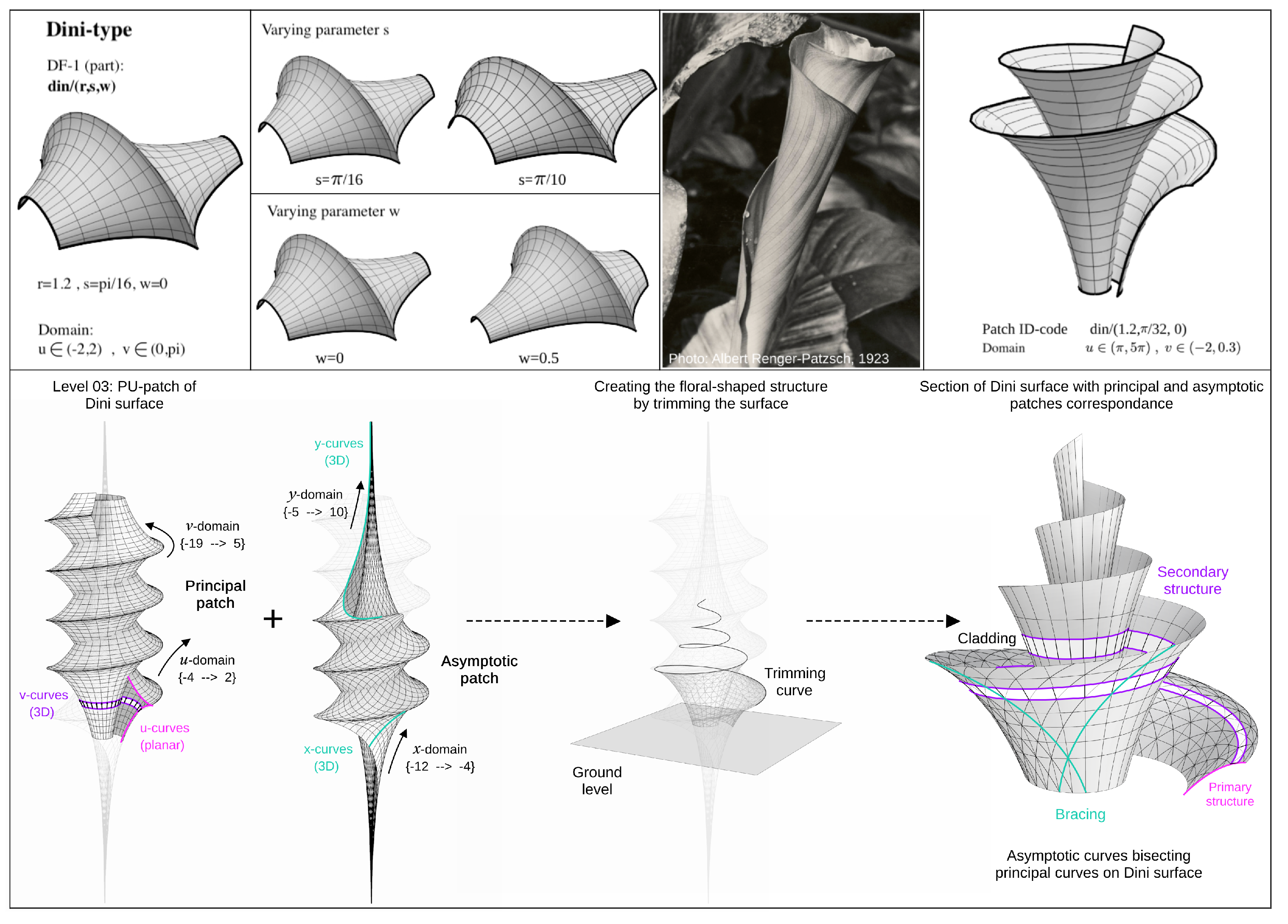
Figure 3.
Structural components
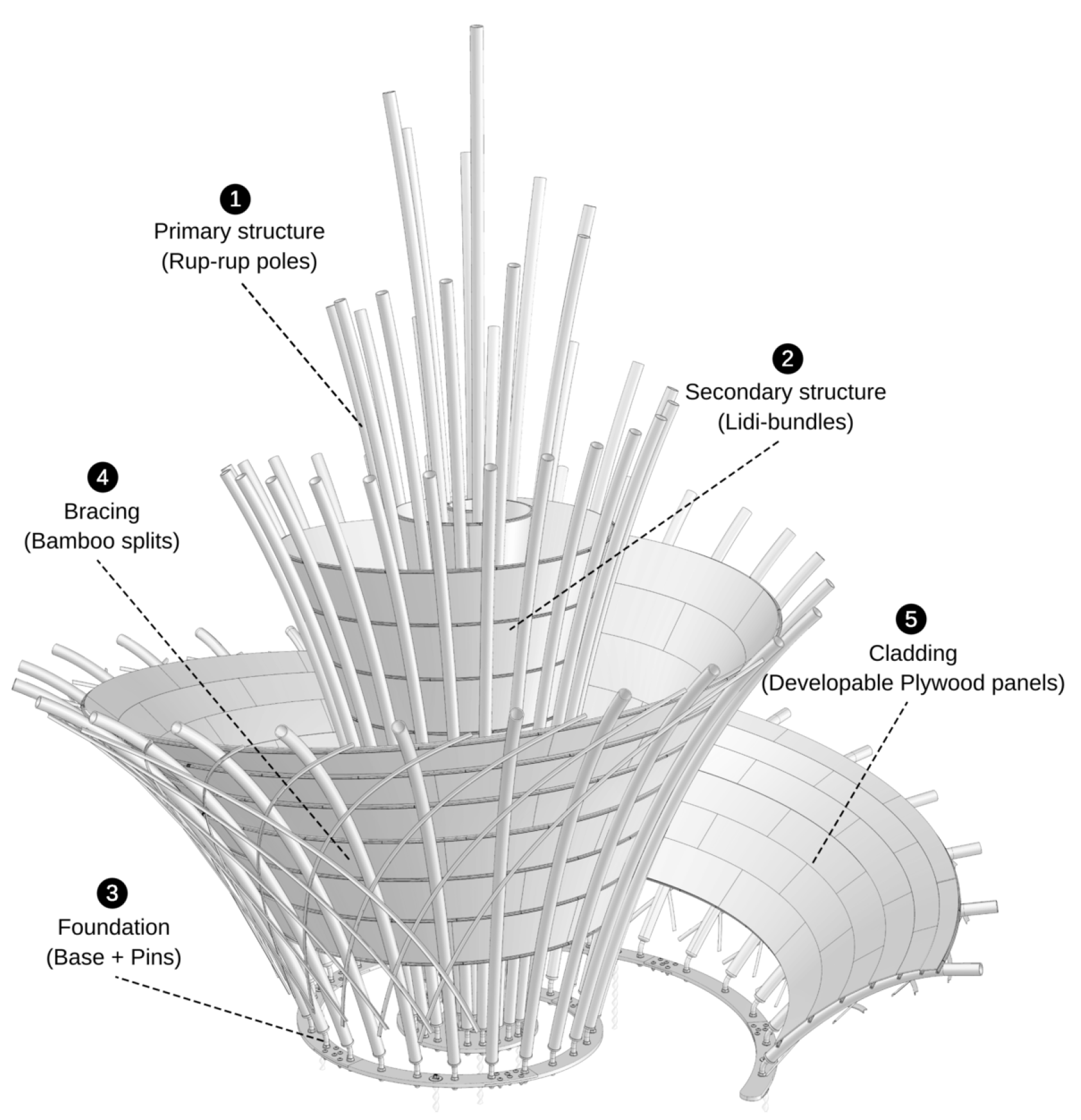
Figure 4.
Calculating the "average" curvature angles on the associated planar curve C.

Figure 5.
Tracing the curvature angles at lengths and , and bending the pole to obtain the curved shape following the associated planar curve.
Figure 5.
Tracing the curvature angles at lengths and , and bending the pole to obtain the curved shape following the associated planar curve.
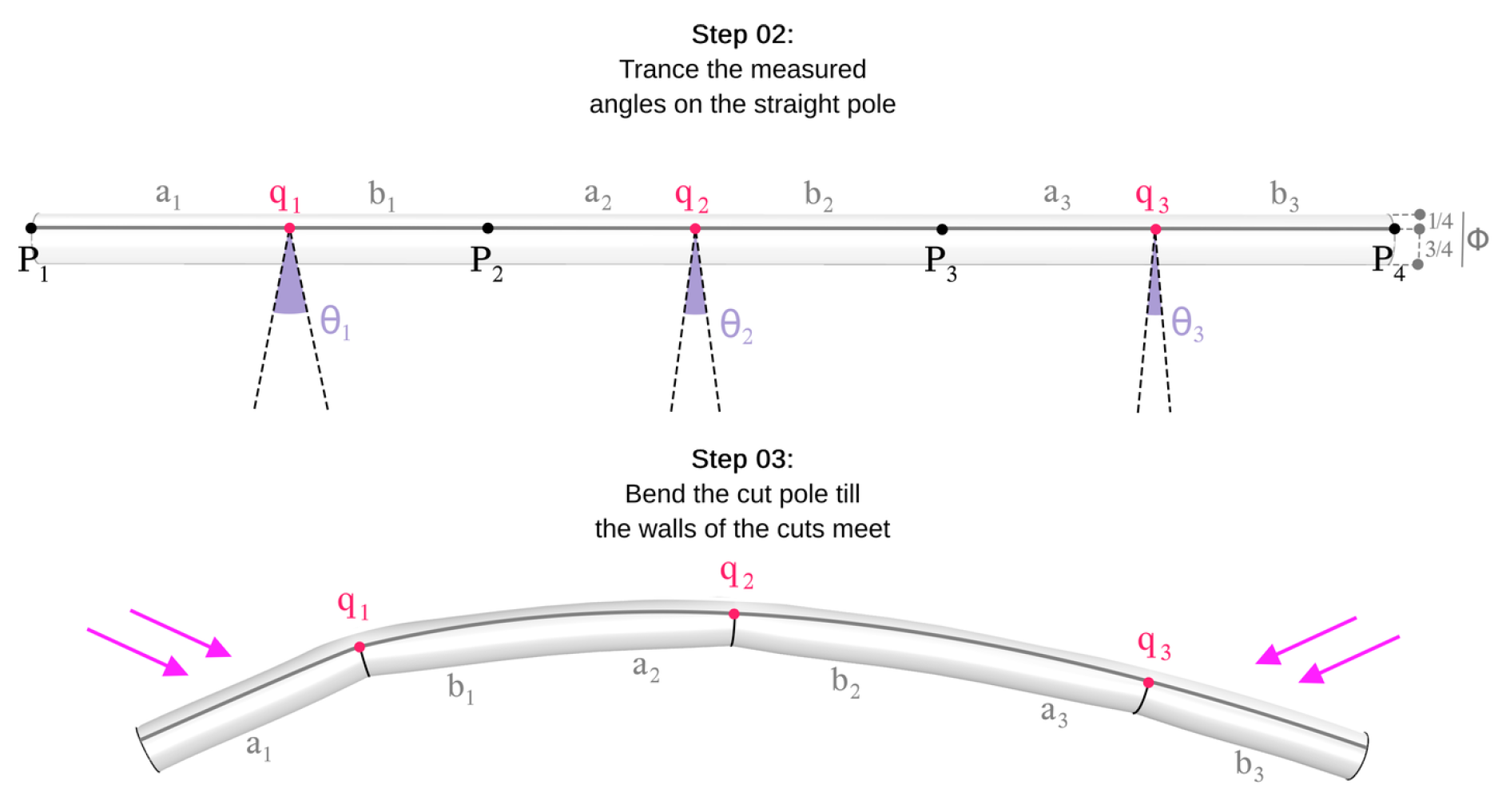
Figure 6.
Attaching a bamboo split to the cut pole to maintain its shape.
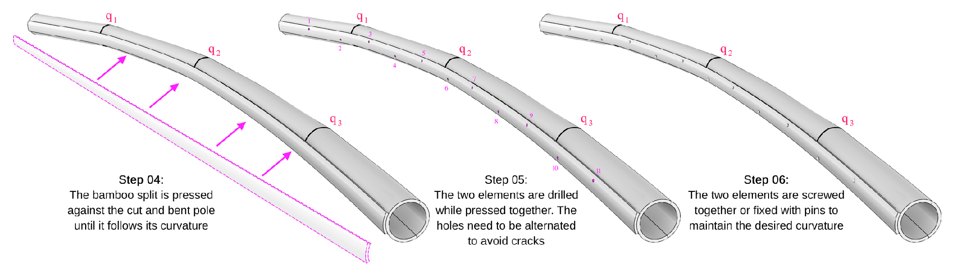
Figure 7.
Fabricating bamboo splits from a whole pole.
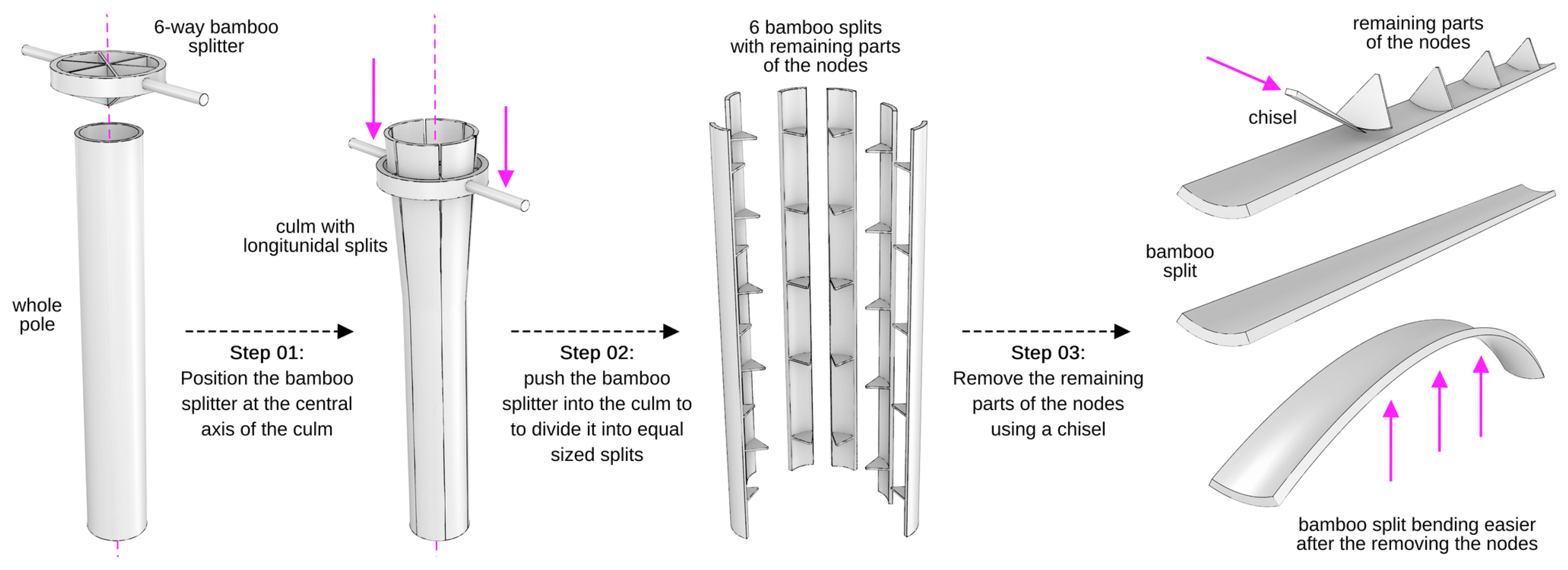
Figure 8.
Mechanism of Rup-rup pole component.
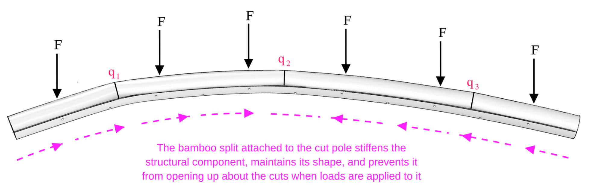
Figure 9.
Determining the number of splits in the Lidi-bundle for each section of the spatial curve.
Figure 9.
Determining the number of splits in the Lidi-bundle for each section of the spatial curve.
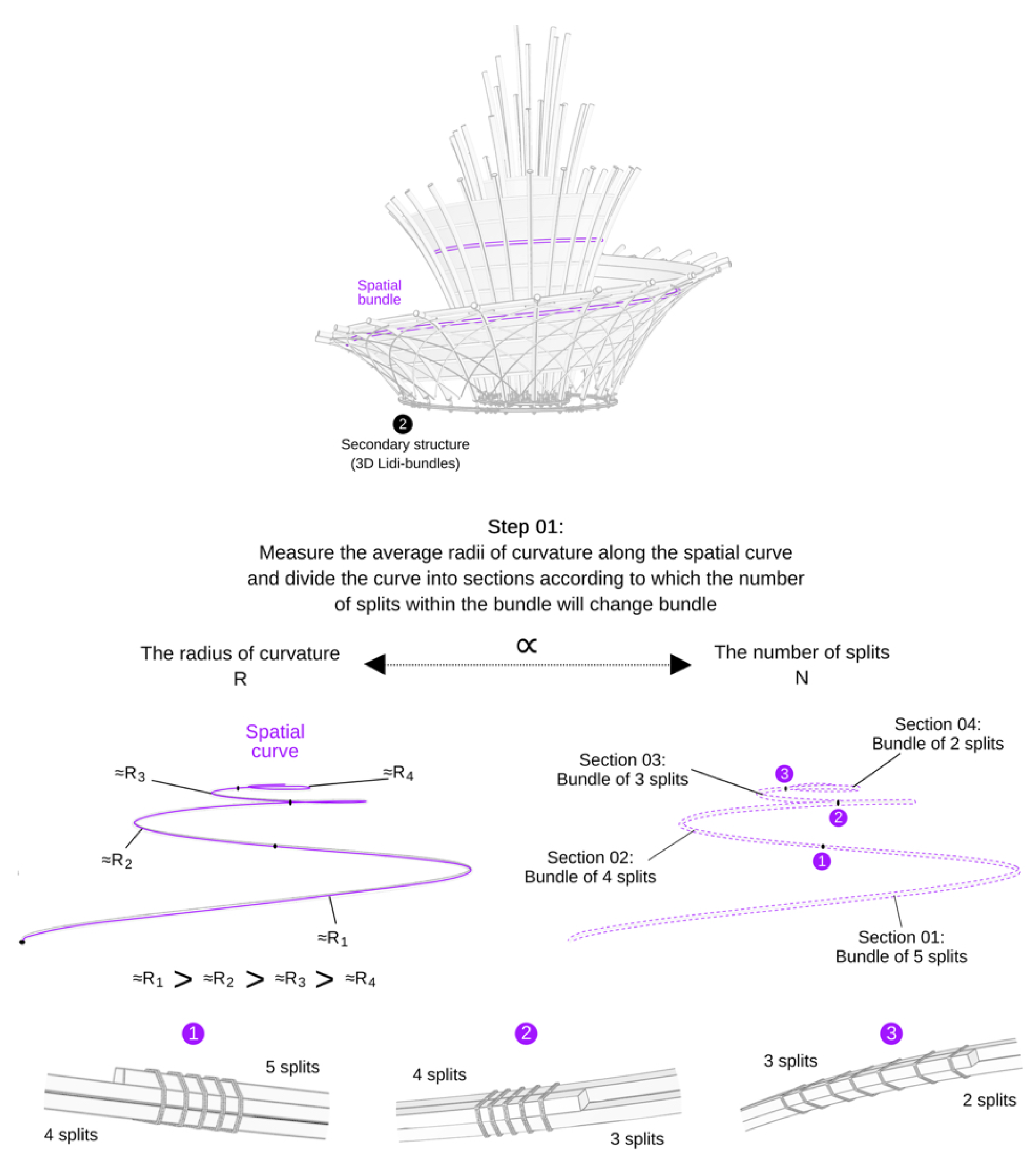
Figure 10.
Making a Lidi-bundle of bamboo splits to trace a spatial curve.
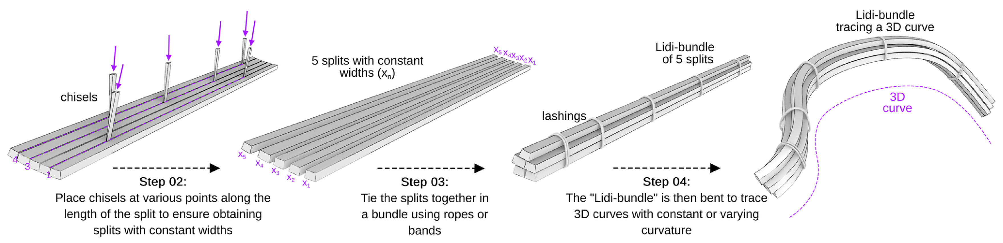
Figure 11.
Buckling effect based on the distance between two fixed points.
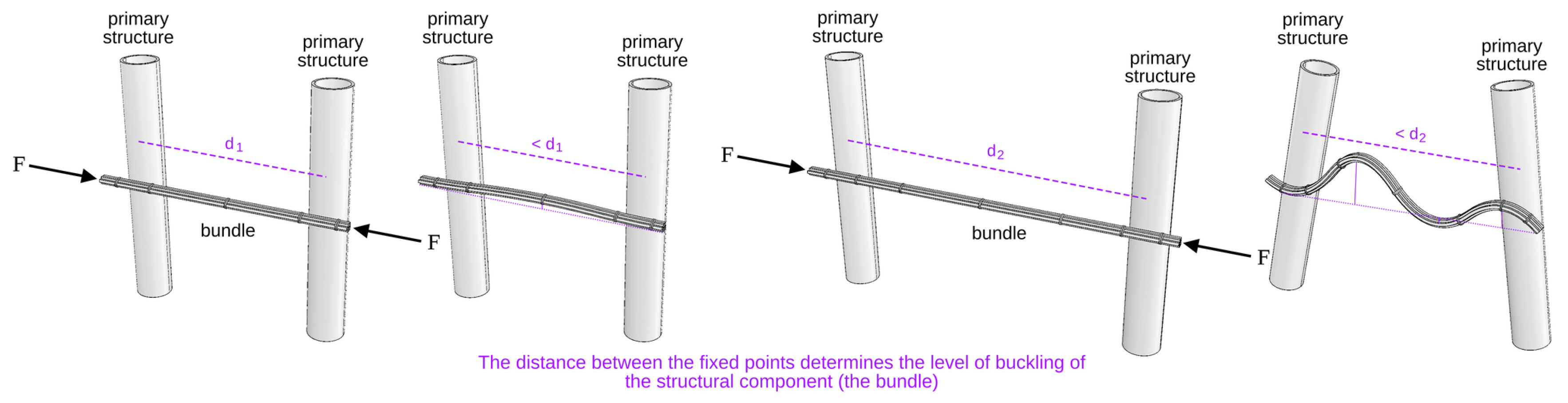
Figure 12.
Shrinking distances between poles.
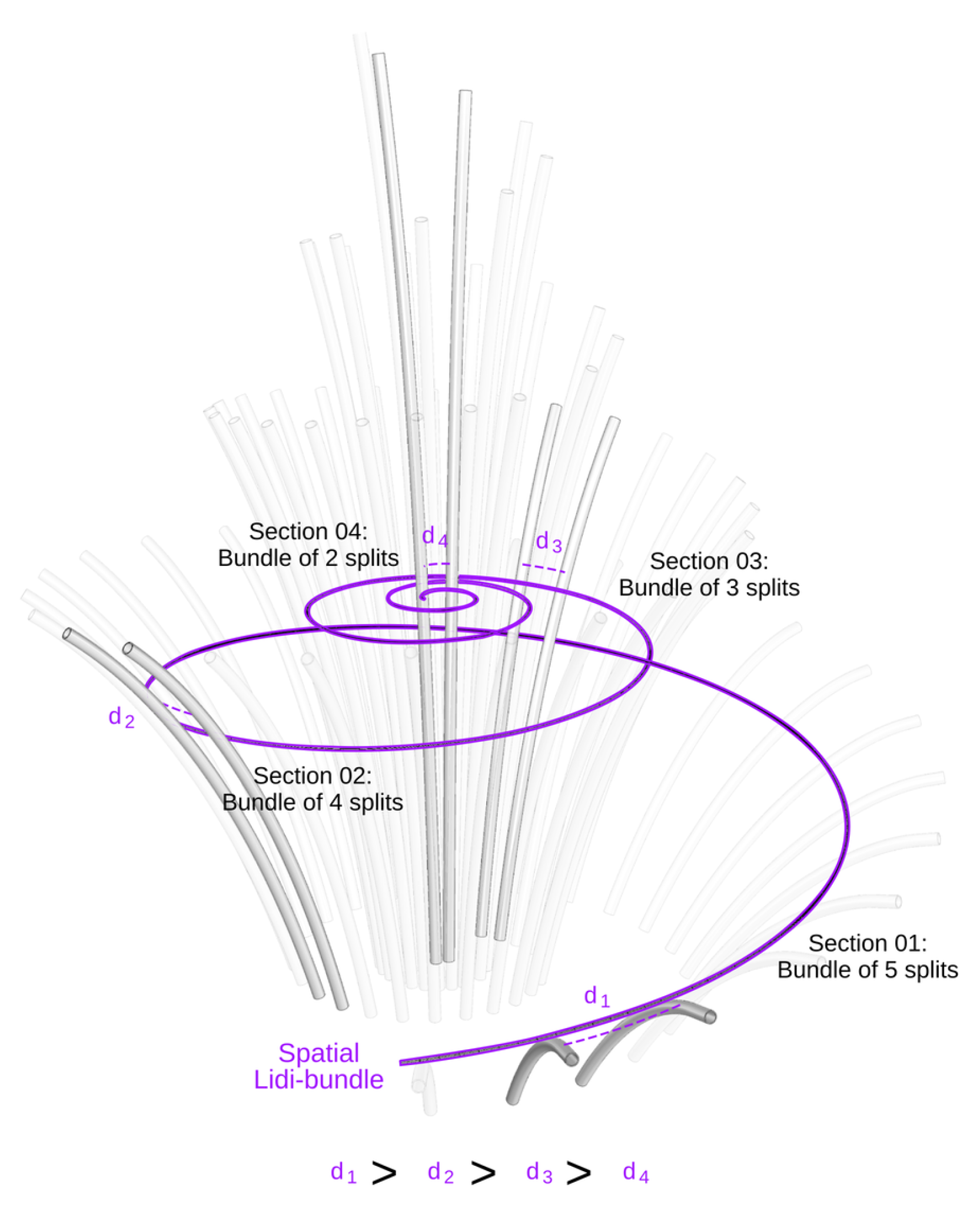
Figure 13.
Designing the base of the structure in relation to the wind load.
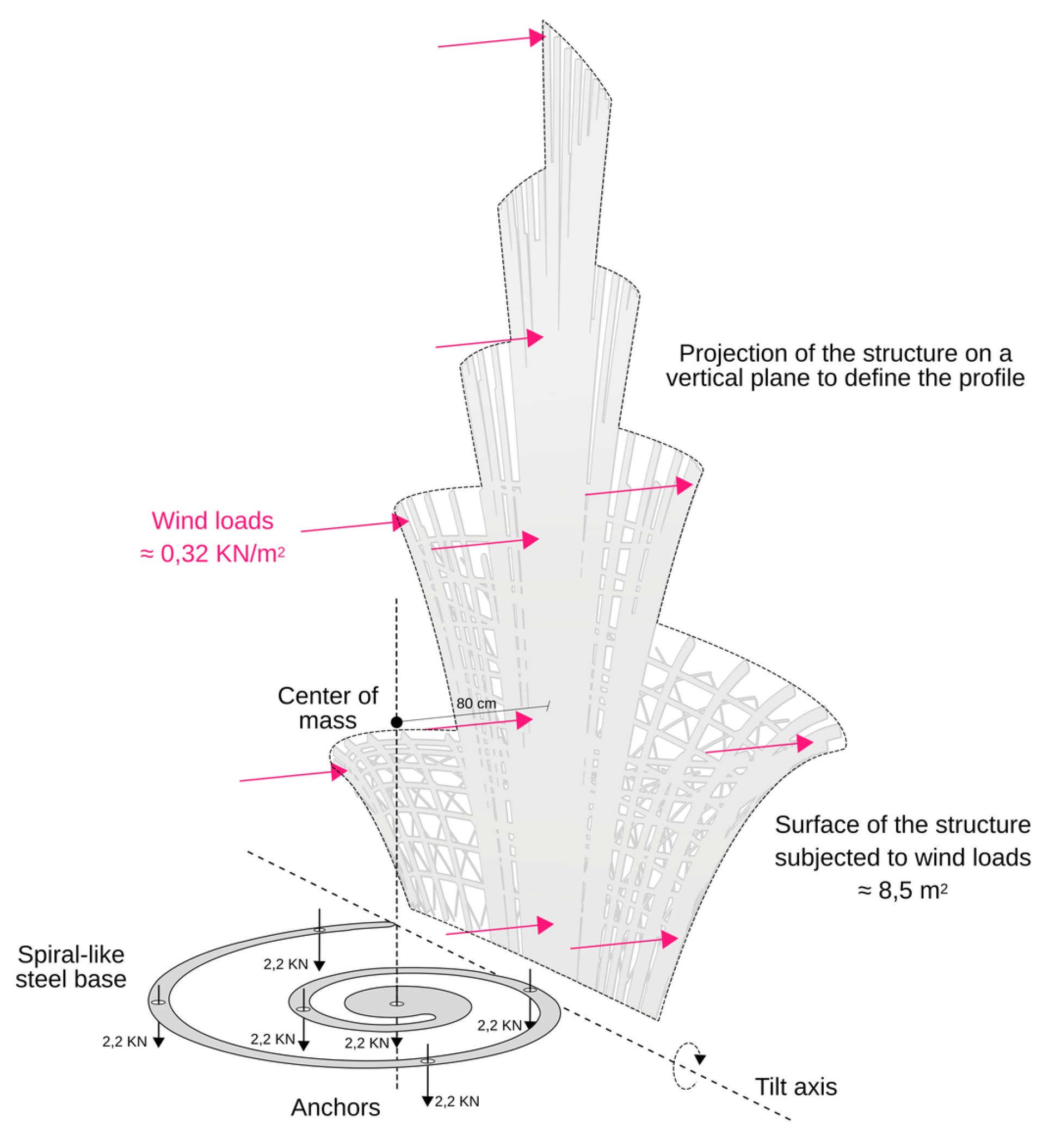
Figure 14.
Installation of the metal base.
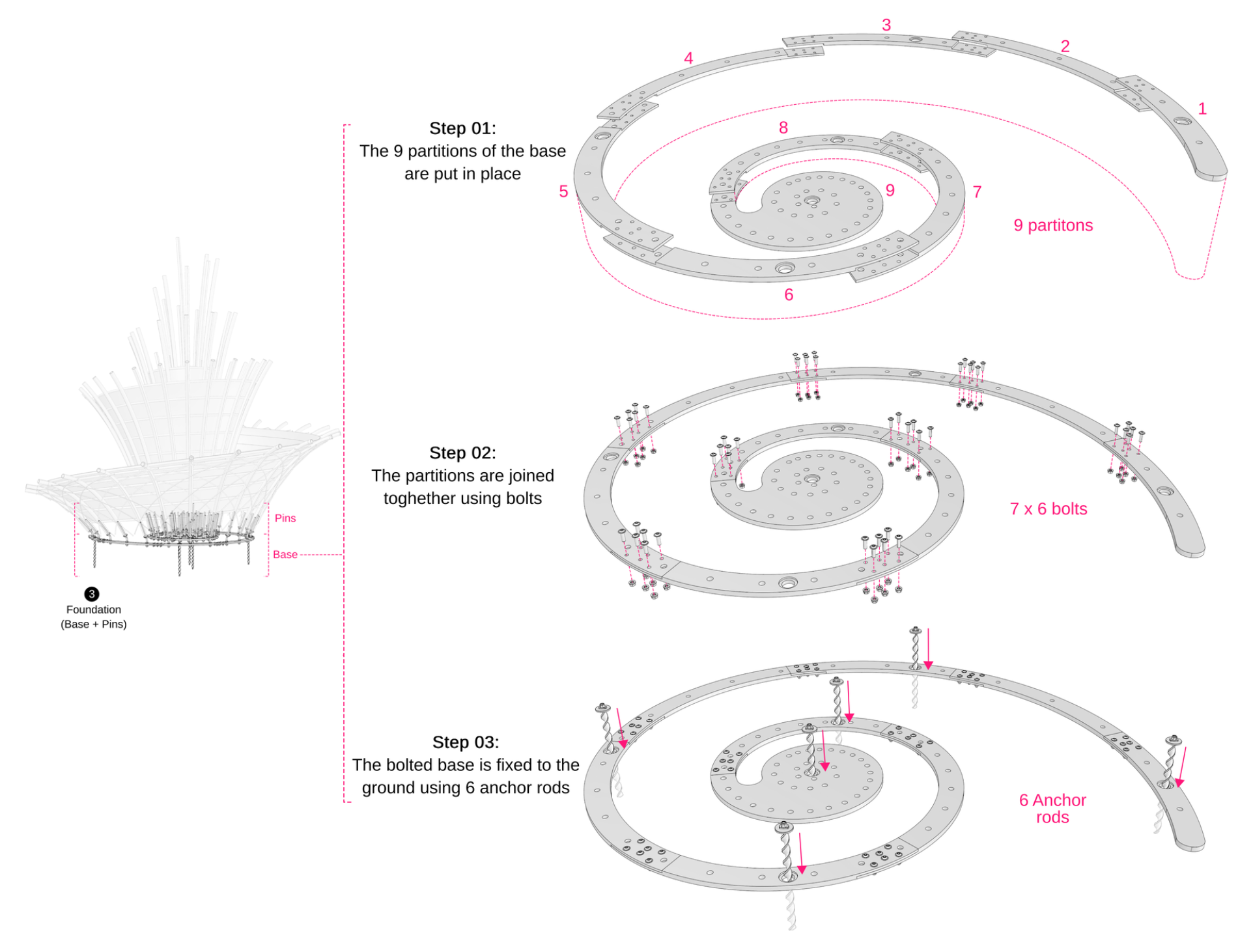
Figure 15.
Creating a bolted connection: Above: piercing the first node and inserting the threaded pin. Below: drilling into the pole wall.
Figure 15.
Creating a bolted connection: Above: piercing the first node and inserting the threaded pin. Below: drilling into the pole wall.
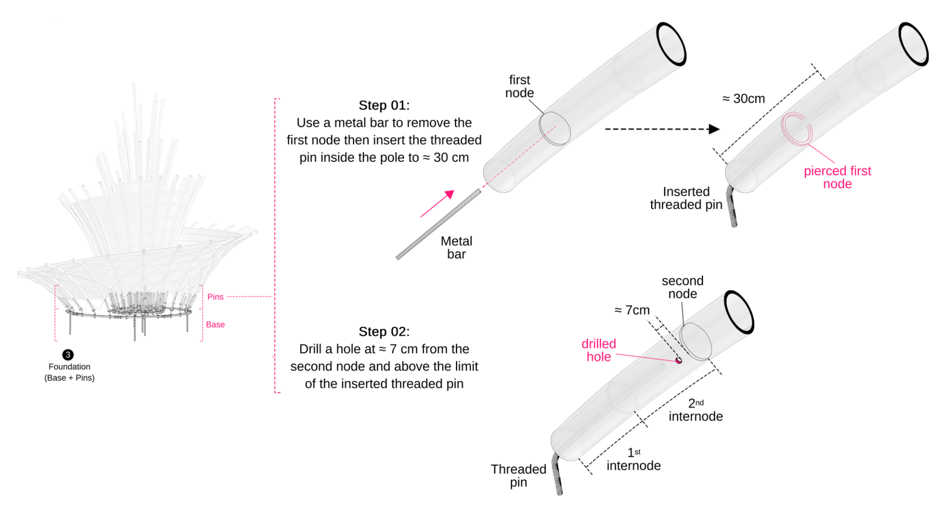
Figure 16.
Creating a bolted connection. Left: Capping the opening. Middle: Fastening the cup to the threaded pin. Right: Filling the cavity with mortar.
Figure 16.
Creating a bolted connection. Left: Capping the opening. Middle: Fastening the cup to the threaded pin. Right: Filling the cavity with mortar.
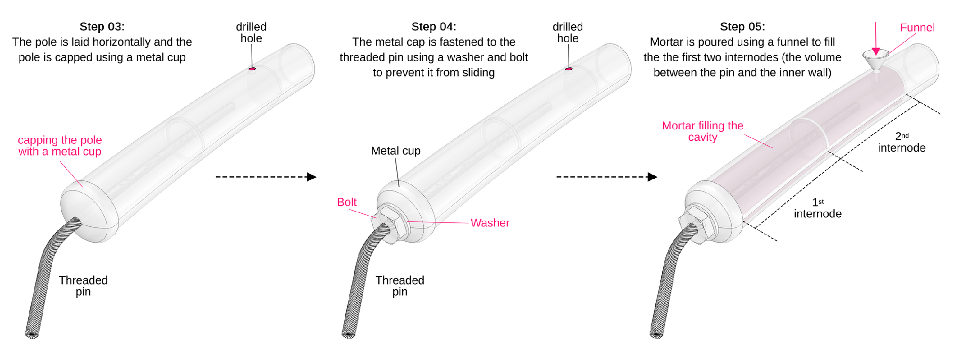
Figure 17.
Joining the two parts of the foundation.
Figure 18.
Bracing by thin bamboo splits.
Figure 20.
Components before assembly.
Figure 21.
Inserting the anchors.
Figure 22.
Installing the steel base.
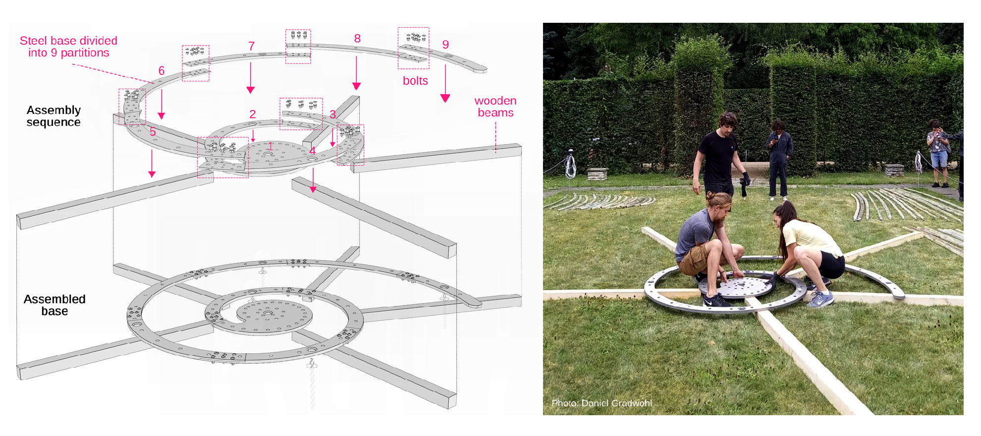
Figure 23.
Installing the primary structure

Figure 24.
Installing the secondary structure
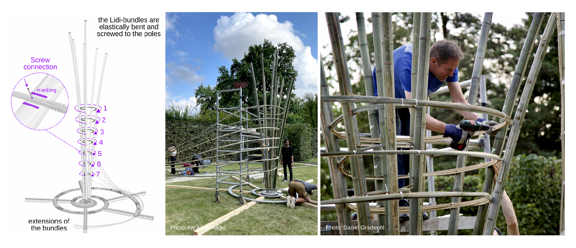
Figure 25.
Installing the bracing elements
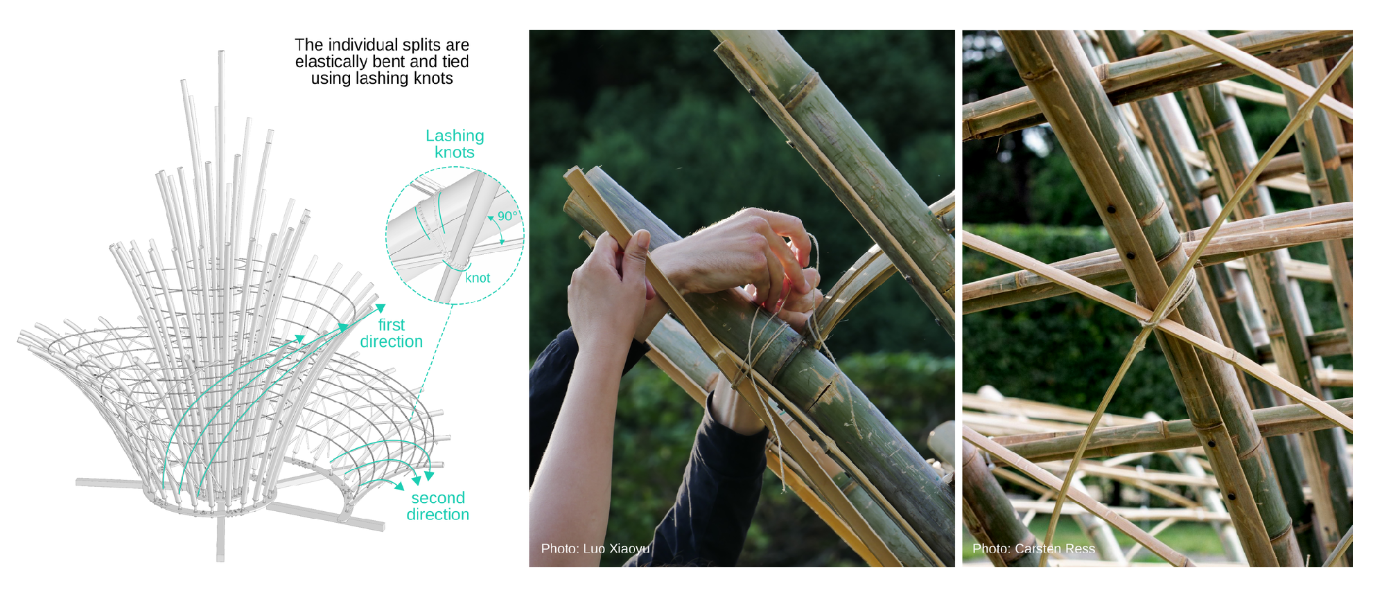
Figure 26.
Securing the structure in place
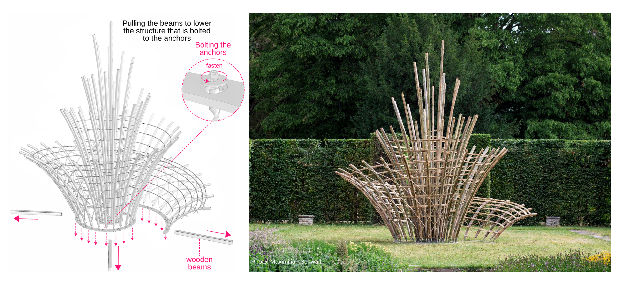

Table 1.
The impact of these considerations on the design and construction of the bamboo structure.
| Considerations | Impact on design, fabrication, and construction |
|---|---|
| The theme of the Plant fever exhibition | The shape of the structure (floral) and the choice of the building material (bamboo) |
| The garden as a heritage site | The off-site fabrication of structural components (prefab), the chosen type of foundation (above-ground base with anchors to avoid damaging the grass), and the minimization of the structure’s footprint, etc. |
| The narrow access passages to the site | The division of the prefabricated structural components into partitions, the falsework-free construction method, etc. |
| The interdiction of cranes, falsework, etc. | The partitioning of prefabricated structural components into sizes manageable by a maximum of two people, along with simple assembly methods, etc. |
Table 2.
Mortar composition
| Component | Amount per 1 [kg] |
|---|---|
| Binder BMK-D5-1 | 850 |
| Portland cement CEM I 52,5R | 50 |
| Quartz Sand 0,06 – 0,3 mm | 325 |
| Sand 0 – 1 mm | 920 |
| Water | 210 |
| Superplasticizer LIESEN 877 | 15 |
| Accelerator PANTAQUICK RSM 920 | 25 |
Disclaimer/Publisher’s Note: The statements, opinions and data contained in all publications are solely those of the individual author(s) and contributor(s) and not of MDPI and/or the editor(s). MDPI and/or the editor(s) disclaim responsibility for any injury to people or property resulting from any ideas, methods, instructions or products referred to in the content. |
© 2025 by the authors. Licensee MDPI, Basel, Switzerland. This article is an open access article distributed under the terms and conditions of the Creative Commons Attribution (CC BY) license (http://creativecommons.org/licenses/by/4.0/).
Copyright: This open access article is published under a Creative Commons CC BY 4.0 license, which permit the free download, distribution, and reuse, provided that the author and preprint are cited in any reuse.


