
Submitted:
31 March 2025
Posted:
01 April 2025
You are already at the latest version
Abstract
The church of Saint Felix in Girona (Spain) is crowned by an octagonal bell tower with a stone pinnacle at each corner. I was built with dry-joined stone masonry. To reinforce the connection between the stone blocs of the pinnacles, a wooden log was placed in the cen-ter, spanning the stone structure, thorough a central hole carved into it. Nowadays, the inner structure has completely disappeared. During the maintenance and repair works, it was decided to restore the reinforcement’s functionality by installing a titanium bar. To determine the length of this metallic inclusion, a study was conducted that includes the effect of gravitational, wind and seismic forces. Due to the uncertainty associated to such model, a multi-approach was carried out combining numerical and scaled experimental models. Experimental results demonstrate that pinnacles need to be reinforced with a ti-tanium bar of the length of its height.
Keywords:
stone pinnacles
; numerical models
; scaled experimental models
; Girona’s stone
1. Introduction
The bell tower of Saint Felix church is part of the skyline of Girona together the Cathedral. The construction of this Gothic tower began in 1368 under the direction of master stonemason Pere Sacoma. In the building records of the Saint Felix church appear cited as Pere Sacoma, Pere ça Coma, Pere de Coma or Pere de Comes and the ground plan of the bell tower, drawn by the same architect, is also preserved [1]. He built in the tower approximately until 1391 and the tower was finally finished at the end of de sixteenth century (probably in 1572).
The bell tower of Saint Felix follows the gothic typology in all its structure in spite of its year of completion. Tower was built in three levels; first level arrived at church roof level and was built under supervision of Pere Sacoma. The second level, built at the middle of sixteenth century, arrived at the level of the bells. And finally, the last level arrived at the level where the truncated spire starts together with the pinnacles. Thus, the type of bell tower, with an octagonal irregular ground plan, is composed of three stepped bodies supported by eight buttresses crowned by pinnacles and a truncated central spire [2].
The aim of this article is to analyze the behavior of the pinnacles of the bell tower of Saint Felix church, some of which are inclined and deteriorated for various reasons, by the action of wind and earthquakes using numerical models and a scale model made of the same material as the bell tower, limestone. In short, the aim was to evaluate the need to reinforce these singular elements as the restoration work was being carried out on the bell tower.
2. Structural analysis.
2.1. Basics
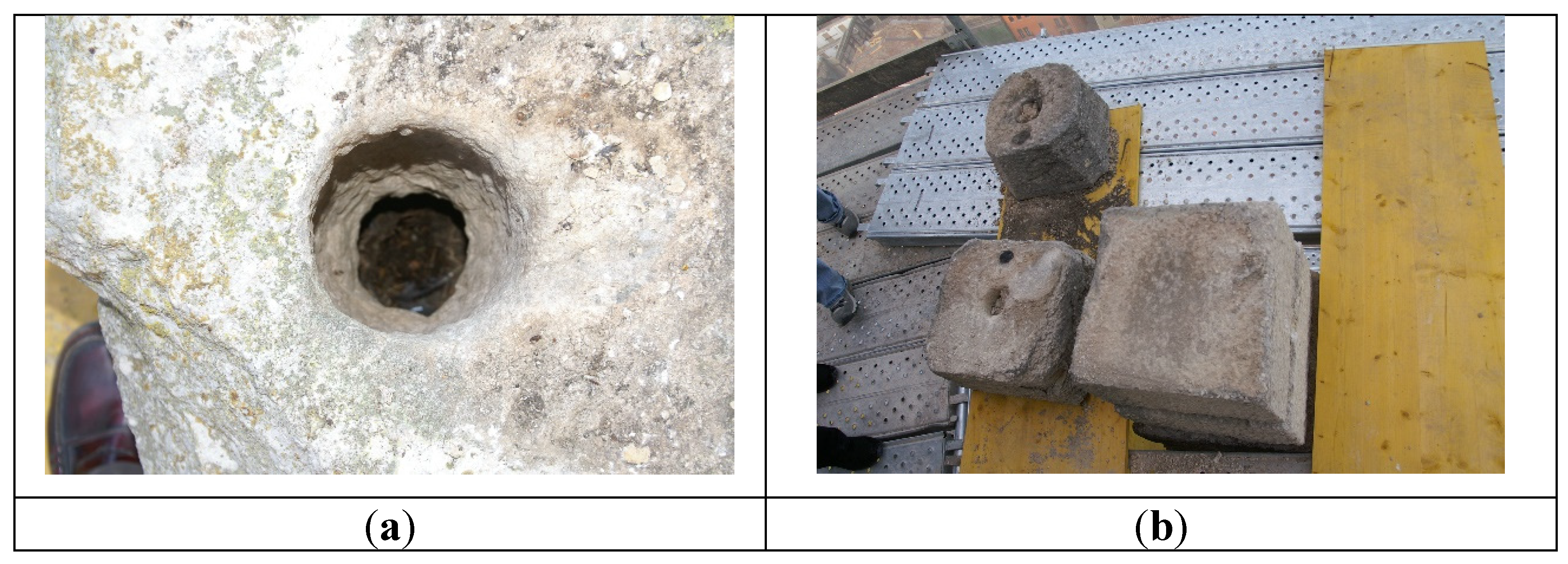
Lateral stability and, to some extent, load transfer between the different layers of stone was previously ensured by a wooden log situated in its central part. Due to time, environmental conditions and biotic agents, the rudimentary connection between the successive rings that form the pinnacle no longer exists.
The restoration team decided to include a titanium bar to functionally replace the old connector. Functional issues as well as the costs derived from the purchase and installation of this element, justified studying how to minimize the length of such a reinforcement.
The self-weight of stone structures of this nature rarely represents a critical state and generally has a stabilizing effect. In [3] the theory of limit analysis applied to stone structures states that the allowable compressive stress can be considered infinite. Due to its position, the pinnacle is mainly affected by horizontal forces of wind and seismic origin. The value of such forces has been calculated using Spanish regulations [4,5]. These forces introduce bending moments and shear forces into the structure.
Due to the lack of continuity between the constituent elements - stone masonry laid with dry joints (without mortar) - this type of structure cannot transfer tensile forces. Then, the stability will be guaranteed by equilibrium assuring that the resultant load remains in the central core defined by the middle third rule.
Figure 1.
View of the hole where the wooden log was formerly allocated: (a) Whole at the top piece of pinnacle (b) Pieces of the pinnacle disassembled.
Figure 1.
View of the hole where the wooden log was formerly allocated: (a) Whole at the top piece of pinnacle (b) Pieces of the pinnacle disassembled.
The failure modes considered in the study are sliding (horizontal displacement between layers of masonry stone) and overturning (rotation of the section due to the presence of excessive tensile stress).
2.2. Geometry
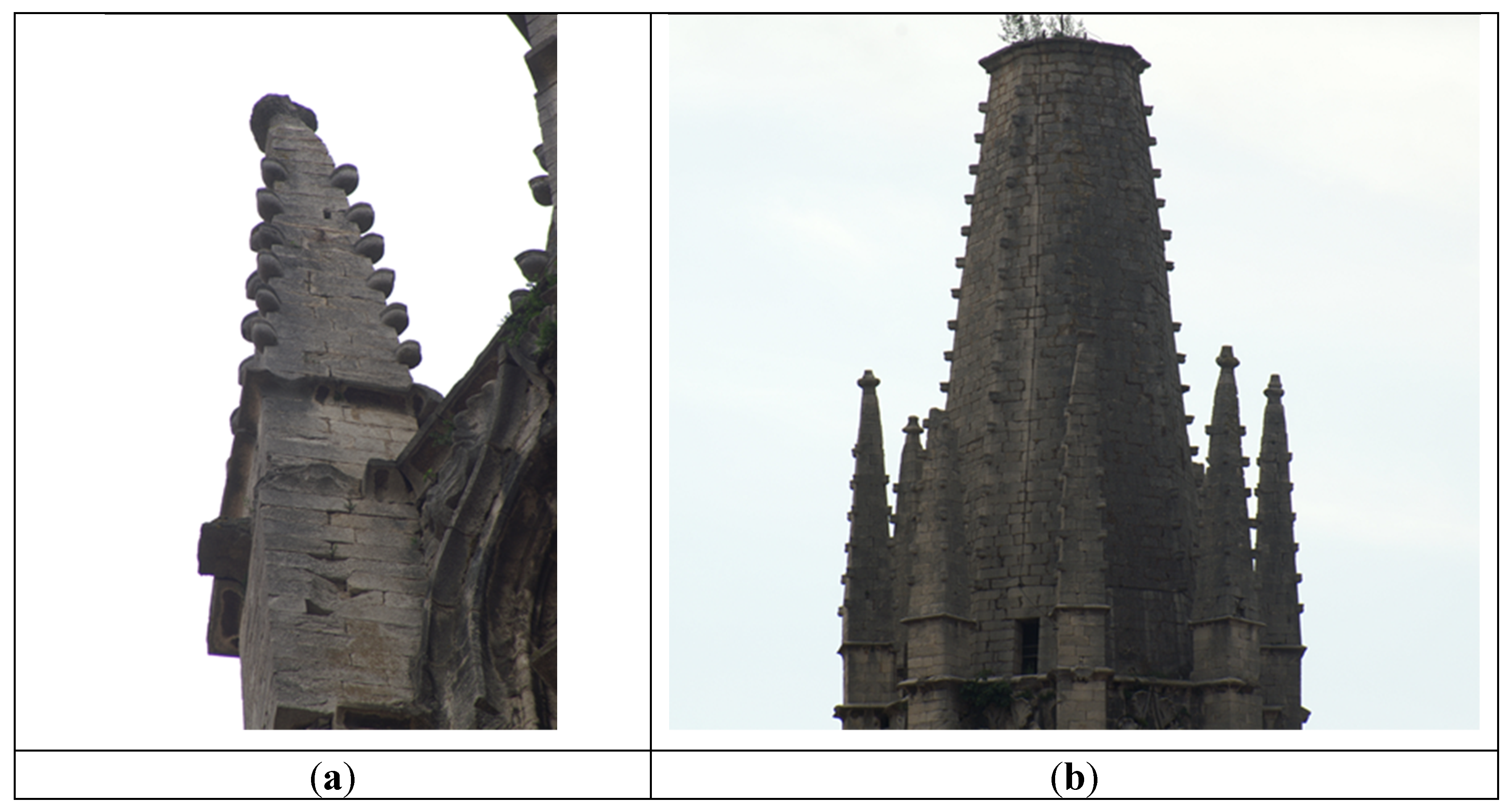
The plan projection of the bell tower of the church of Saint Felix consists of an octagon with irregular sides. A sudden change in elevation dimension allows to define the geometry of the upper part of the tower, and accommodate the eight pinnacles under study.
The pinnacles are approximately eight meters high. The cross-section of the pinnacles at the starting point corresponds to a rectangle measuring 1.32 x 1.11m. The pinnacle’s cross-section decreases in height. The cross-sectional dimensions at the highest point are approximately of 0,54 x 0,53m.
Figure 2.
Truncated spire and pinnacles of Saint Félix church: (a) Detail of vertical deformation of pinnacle; (b) General view of deformation of pinnacles.
Figure 2.
Truncated spire and pinnacles of Saint Félix church: (a) Detail of vertical deformation of pinnacle; (b) General view of deformation of pinnacles.
2.3. The stone of Girona
Tower well of Saint Felix church was built with a limestone known as “Girona stone”. It is a compact, coherent and relatively homogeneous nummulitic limestone rock formed in the Middle Eocene period (Lutecian). It has a massive microcrystalline appearance where fossilized nummulites ranging from 0.5 to 6 cm in diameter stand out. Nummulites are an extinct genus of benthic foraminifera (unicellular organisms that lived on the depths of seas and oceans). They have survived well preserved to the present day because they had a fairly resistant calcareous shell.
Girona’s stone has three main varieties, but its chemical composition is mainly made up of the following minerals: calcite (83.00%), dolomite (2.50%), feldspar (9.50%) and quartz (5.00%). It has a low open porosity, a low and a relatively slow absorption capacity, a slow rate of drying, a high resistance to compression and a medium modulus of elasticity [6].
Table 1 show the properties of the stone used in the pinnacle construction.
Compression stress and flexural stress, determined using a four-point test, for different varieties of Girona’s stone was determined by [7] in an extensive experimental campaign. The results are shown in Table 2 and Table 3.
Additional tests were carried out to characterize some of the critical properties. The most relevant was the friction coefficient. No information was available on this variable. This prompted a testing campaign to determine it. The result was 0,66.
2.4. Load estimation
2.4.1. Gravitational forces
Gravitational forces are primarily due to self-weight. The density of the material was determined experimentally and compared with values available in the literature. The volume was calculated from the graphic documentation included in the restoration project.
2.4.2. Wind forces
Wind is a dynamic phenomenon that can be described by decoupling it into different effects. A rigorous analysis of the wind affecting the pinnacle using tunnel wind tests, is beyond the scope of the project. It is therefore a matter of carefully choosing the hypotheses to be used in the calculation, to guarantee that the intervention to be carried out is safe enough.
Stone pinnacles have been studied in a wind tunnel tests [8]. The static wind forces are expressed using the standard drag equation:
the drag stablished (Cd) was stablished using the results of the wind tunnel tests through back-calculation from measured strains. The chosen values range between 1,20 – 1,50.
The study concludes that, for this kind of structure, the dynamic effects are small. In [9] the vibrating behaviour of stone pinnacles, is studied, arriving to a similar conclusion. The basic value of the dynamic pressure of wind is determined similarly in [10]. The basic velocity of wind to be applied is 29 m/s. The standard drag equation will be used in this study.
2.4.3. Seismic forces
For the sake of simplicity, the pinnacle is considered as a cantilever structure, fixed in the base, as if the bell-tower wasn’t attached to the building. This consideration defines an unfavourable scenario, which will result in a conservative estimate of the seismic forces.
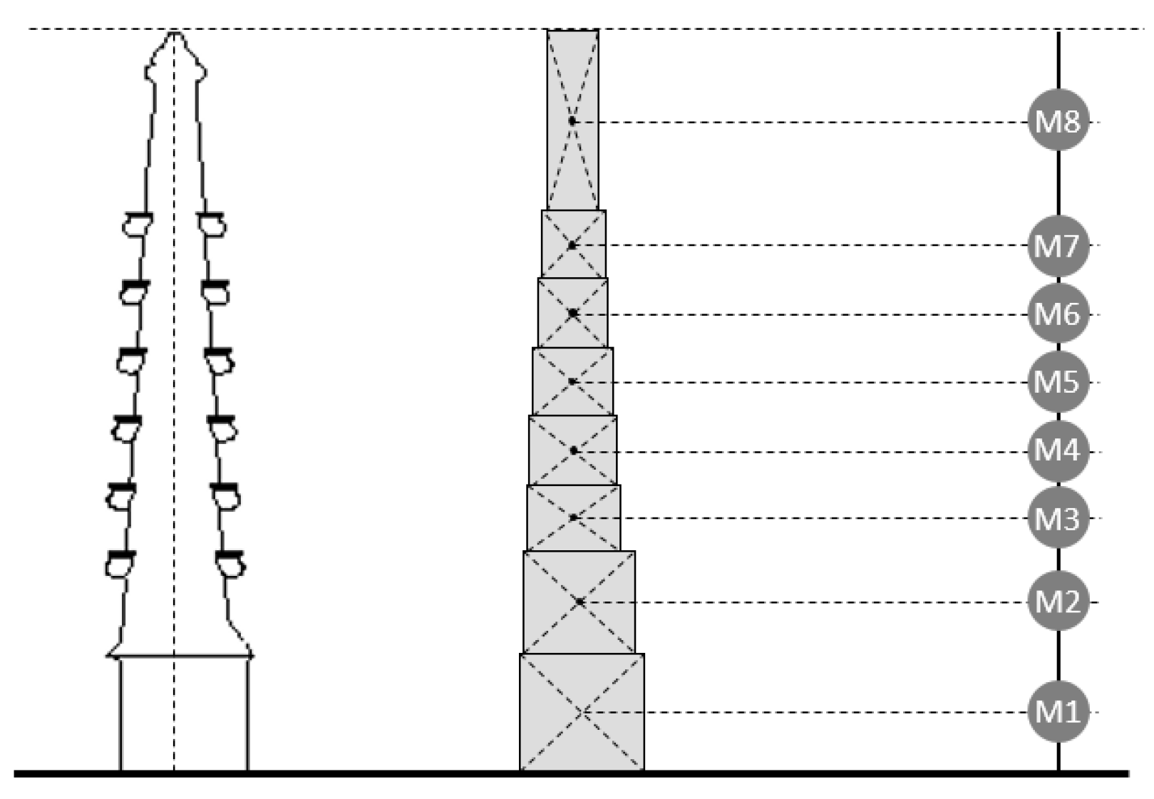
The simplified method proposed in the regulations [4], where the structure can be compared to a pendulum with concentrated masses, was considered sufficiently representative for this study (figure 3). The basic seismic acceleration to be applied in Girona, is 0.08 ag/b, and the contribution coefficient equals 1.00. Therefore, the seismic constraints are not extremely demanding. The problem stems from the position of the element and its weakness against horizontal forces.
Figure 3.
Simplification to a model of a pendulum with concentrated masses.
The church of Saint Felix is founded on rock. The soil coefficient considered is 1.00. Live loads are negligible compared to dead loads. Consequently, the mass considered in the calculations will correspond mainly to its self-weight. The parameters affecting ductility must be chosen carefully, considering that this type of structure is incapable of dissipating energy.
The fundamental period of the tower is approximately 0.40 seconds. Accordingly, the contribution of a single mode shape has been considered when determining the seismic forces.
3. Analysis approaches
3.1. Introduction
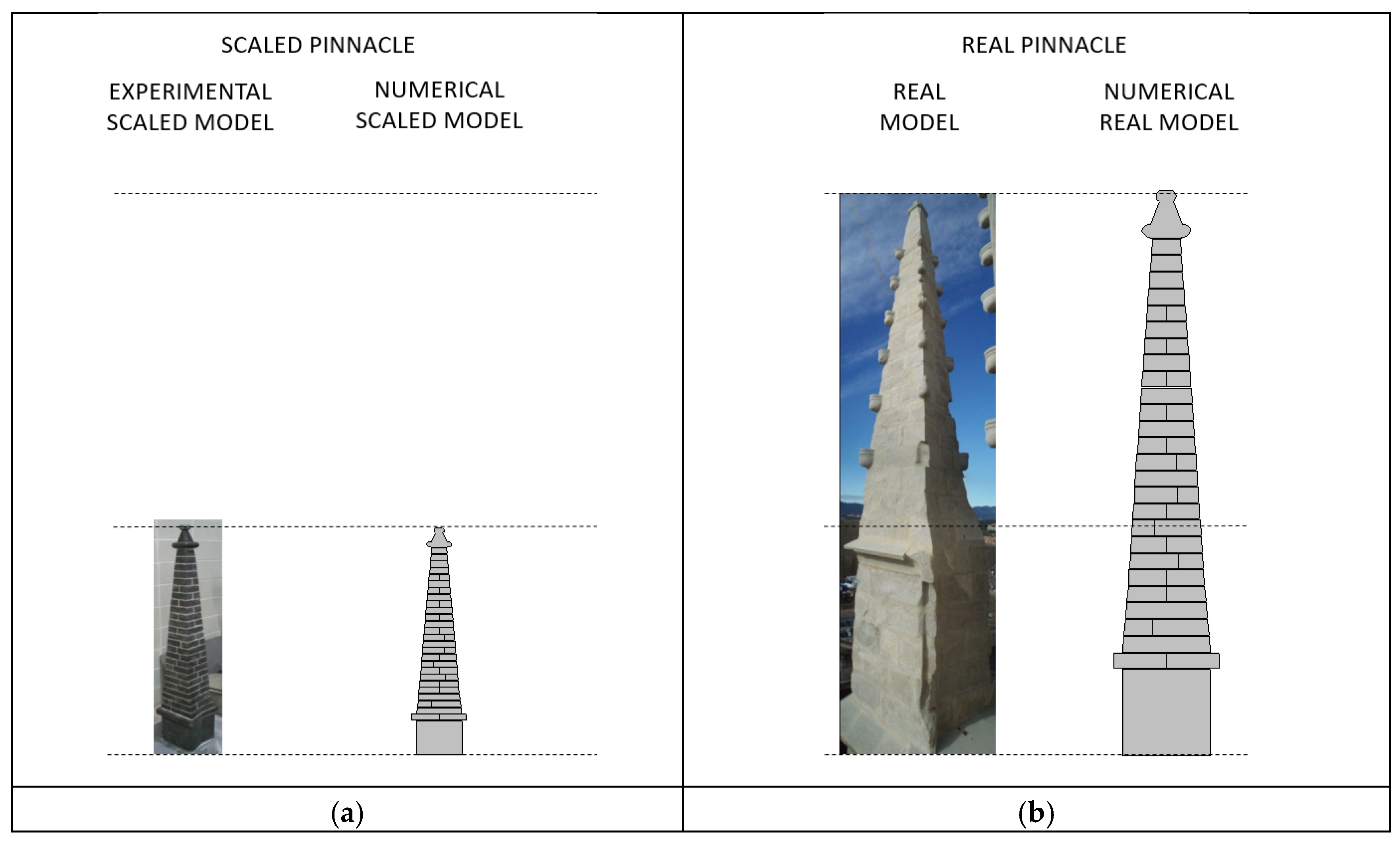
To analyse the pinnacle’s behaviour, numerical and experimental models were combined. The first approach consists of a calibrating the problem using a scaled real model under laboratory conditions. Once a representative numerical model of the scaled structures will be available, the analysis will be transferred to the real-life situation.
Figure 4.
Experimental, real and numerical models: (a) Scaled pinnacle models; (b) Real pinnacle models.
Figure 4.
Experimental, real and numerical models: (a) Scaled pinnacle models; (b) Real pinnacle models.
3.2. Experimental scaled model
A 1:5 scaled model of the pinnacle (figure 5) was made using the same material and construction method. This model was used to simulate the effect of horizontal forces on it. For this purpose, a laboratory test was designed.
A step-by-step procedure was carried out consisting of pressing each of the stone rings with a force equivalent to the resultant of the forces located above the analysis plane. The force was applied by a hydraulic piston.
A displacement transducer was used to identify the start of the ring’s displacement. In this way it was possible to experimentally evaluate the behaviour of the pinnacle against sliding caused by horizontal loads.
Figure 5.
Scaled model of pinnacles: (a) Scheme of test; (b) Test in laboratory conditions.
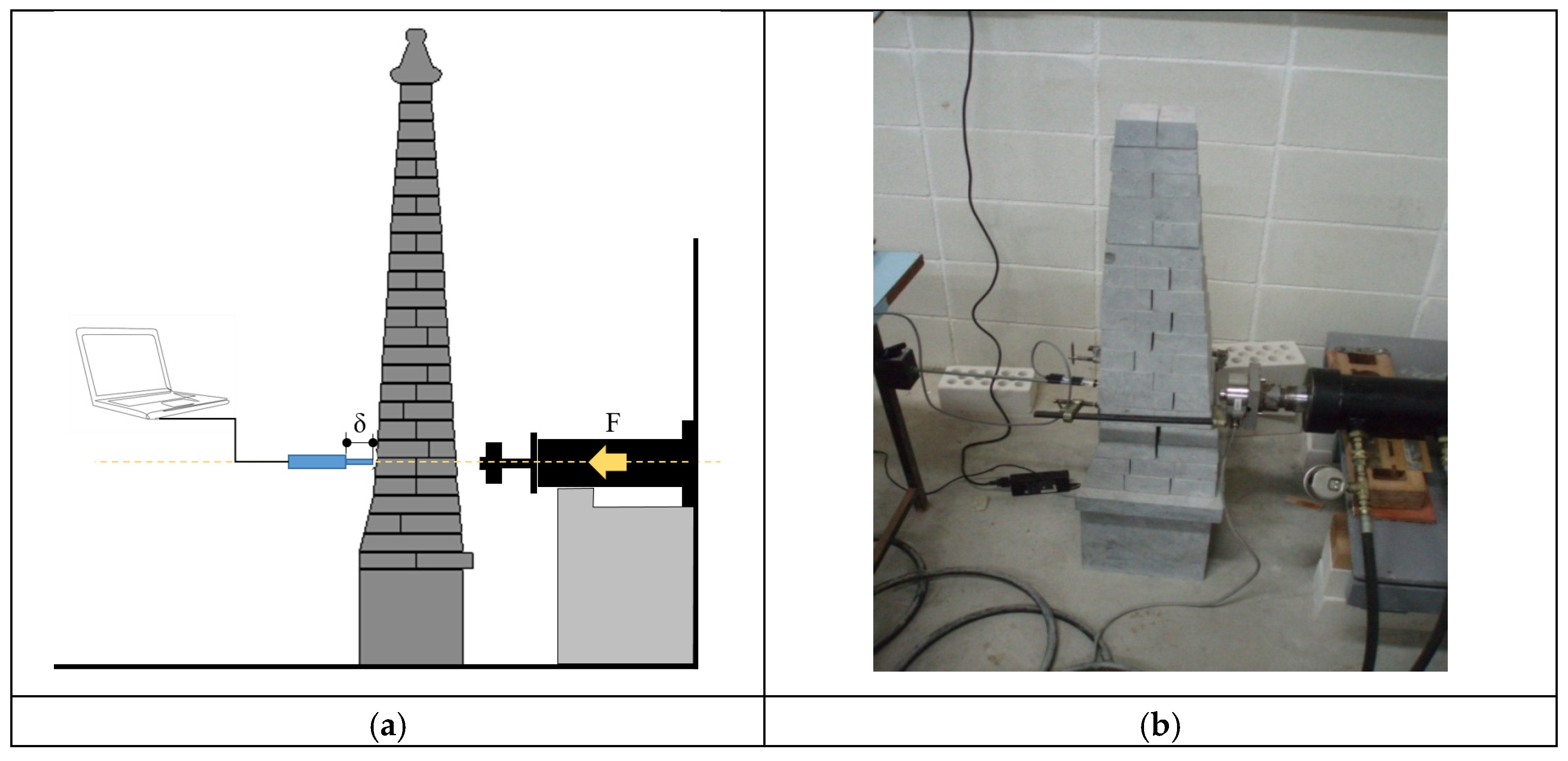
The first ring was located where the friction associated with vertical loads (self-weight) failed to balance the effect of horizontal loads. This information, along with a simple verification of the resulting self-weight value, was used to calibrate subsequent numerical models.
3.3. Numerical scaled model
Once experimentally determined the experimental scaled model response, an equivalent numerical model was calibrated. Masonry components were modelled using SOLID185 from ANSYS® . It is an eight-node solid element, with three degrees of freedom at each node (translations in nodal x, y, and z directions). It supports plasticity, stress stiffening, large deflection and large strain [Ansys].
The variables to calibrate where related to the behaviour of the contact surface between the rings. Such contact surface was represented using CONTA174 and TARGET170.
3.4. The frictional model
The frictional model was based on the Coulomb’ law:
where μ = coefficient of friction for isotropic friction; P = contact normal pressure
τlim=μ·P+b,
b = cohesion.
Where the limit condition is represented by
||τ||≤τlim,
It was considered that cohesion couldn’t be guaranted. Then the original formula for Coulomb’s law
where μ was assigned according to the value experimentally determined.
τlim=μ·P,
3.5. The contact model
The contact model is based on the Augmented Lagrange, a penalty-based formulation where the contact stiffness is used to determine the degree of penetration between two consecutive rings. In such formulation, the stiffness value is updated according to the increasing contact force.
The contact stiffness value is quite high. This is a usual assumption when the expected level of penetration is low, what is usual in masonry representations. The stiffness is updated at each iteration. The stiffness reduction due to the increasing applied load, is used in subsequent iterations.
Figure 6.
Numerical simulation in scaled model: (a) Total deformation at the bottom; (b) Total deformation at the top.
Figure 6.
Numerical simulation in scaled model: (a) Total deformation at the bottom; (b) Total deformation at the top.
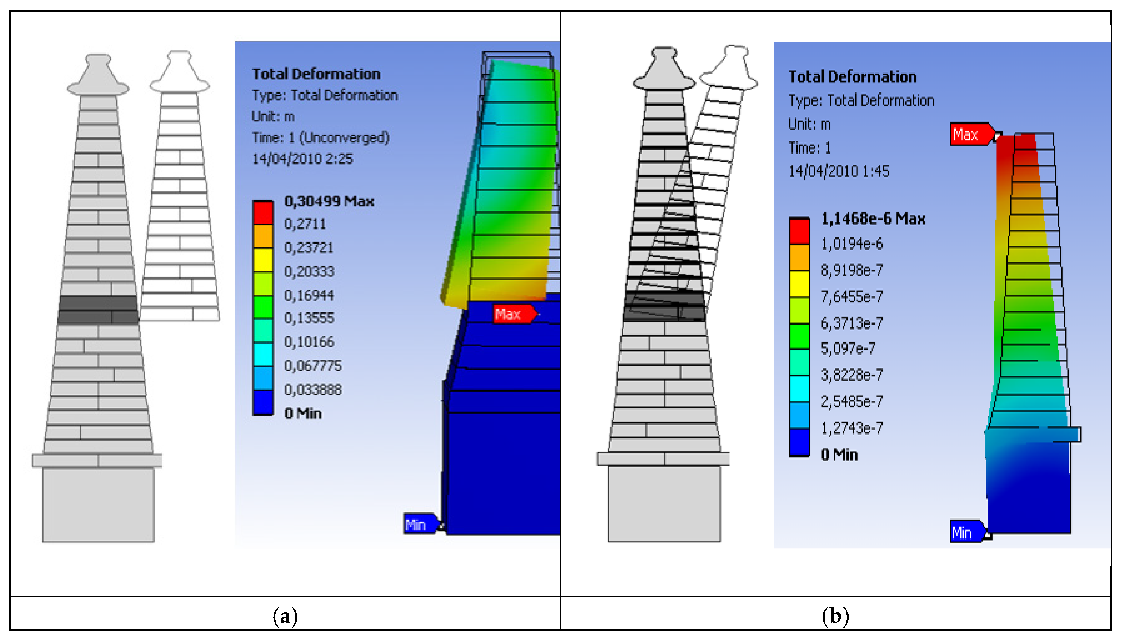
Once the scaled model performed in the same way than the experimental model, a new model at a real scale was prepared.
3.6. Equilibrium approach
An equilibrium approach based on the middle third rule has been used as a complementary tool to verify the quality of the results. The aim is to identify the loss of contact between consecutives layers of stone masonry, based on the appearance of tensile stresses in the area of interest.
As a work hypothesis, it is assumed that the area has no capacity to cope with this kind of stress. This assumption is consistent with the physical reality of a masonry structure without mortar in the joints.
In the Table 4, Table 5 and Table 6, the eccentricities induced by geometry, and the horizontals forces (wind and earthquakes) are determined. Afterwards, these elemental hypotheses are combined.
Once analized the elemental cases, the most feasible combinations where studied. The combination corresponding to a transitory situation (Ctransitory) is proposed in this way:
Ctransitory = γG · egeometric + γQ · ewind,
where γG and γQ represent the value of the dead loads and live loads respectively.
The combination corresponding to an accidental situation (Caccidental) is proposed in this way:
accidental = γG · egeometric + γA · ewind + γA · eseismic,
where γA represent the value of the accidental loads.

Table 8.
Accidental combination.
| Element |
e geometric (m) |
e wind (m) |
e seismic (m) |
Combination |
emax* (m) |
| 1 | 0,10 | 0,20 | 0,23 | 0,53 | 0,22 |
| 2 | 0,05 | 0,19 | 0,20 | 0,44 | 0,20 |
| 3 | 0,00 | 0,18 | 0,19 | 0,37 | 0,16 |
| 4 | 0,00 | 0,17 | 0,16 | 0,33 | 0,15 |
| 5 | 0,00 | 0,16 | 0,15 | 0,30 | 0,14 |
| 6 | 0,00 | 0,14 | 0,12 | 0,26 | 0,12 |
| 7 | 0,00 | 0,12 | 0,11 | 0,23 | 0,11 |
| 8 | 0,00 | 0,10 | 0,08 | 0,18 | 0,08 |
* Maximum eccentricity for the middle third rule.
To determine the required cross-section, the properties of the material to be used are first defined in Table 9. In order to determine the tension, the titanium bar have to withstand, the axial force it must transfer, is calculated (Table 10).
Where D is de distance between the compressed zone and the position of the titanium bar, A equals the compressed area, F is the force supported by the reinforcement and C is the compression stress in the masonry specimen due to the bending moment.
The result indicates that the pinnacle remains precariously stable under the loading states represented by the elementary hypotheses. However, it cannot cope with their combined effects.
On the other hand, a central titanium bar with a diameter of 20 mm, surrounded by a fiber reinforced mortar is enough to reinforce the pinnacle. The bar must be as long as the pinnacle itself.
The result confirms that the estability of the pinnacle doesn’t depend on its safety against the sliding phenomenon.
4. Conclusions
In order to guaranteed the stability of pinnacle subjected to wind and seismic stresses it must be reinforced along its entire length, using a 20 mm diameter titanium bar.
After the study carried out, it can be concluded that the stability of a pinnacle is mainly related to its capacity to withstand the phenomenon of overturning, with sliding between layers of stone being a secondary issue.
Dynamic effects have been analyzed as a quasi-static phenomenon. This involves describing the physical event in a simplified manner. Based on the writings of other authors who have studied this type of structure, it is concluded that the resulting loss of accuracy does not invalidate the analysis.
The use of a multi-approach procedure, based on the combination of experimental and numerical approaches, has proven to be a powerful tool for describing situations with a high level of uncertainty. A good agreement was found between numerical models and handmade approximations.
Author Contributions
Conceptualization, M.Ll. and M.ACh.; methodology, M.Ll..; software, I.C.; validation, I.C., M.Ll. and MA.Ch.; formal analysis, E.G.; investigation, M.Ll.; resources, E.G.; data curation, M.Ll..; writing—original draft preparation, M.Ll..; writing—review and editing, M.Ll. and M.A.Ch.; visualization, J.F.; supervision, E.G. and J.F.; project administration, M.A.Ch. All authors have read and agreed to the published version of the manuscript.
Funding
This research received no external funding.
Acknowledgments
We would like to thank David Garcia and Mireia Fabregas for their technical support for this work.
Conflicts of Interest
The authors declare no conflicts of interest.
References
- Chamorro Trenado, Miquel Angel, Zaragozá Catalán, Arturo, La traza de la torre campanario de la iglesia de San Félix de Gerona, Goya : Revista de Arte : Publicación Bimestral de La Fundación Lázaro Galdiano (2012) 3–15.
- Chamorro, Miquel Angel, Llorens, Francesc, Els Campanars gòtics a les comarques gironines /, Diputació de Girona :, Girona :, 1993.
- J. Heyman, The mansonry arch, 1982.
- D.C.S. NORMA, Parte general y edificación (NCSE-02), BOE 244 (2002) 02.
- C. DB-SE-A, Código Técnico de Edificación, Documento Básico de Seguridad Estructural. Acero. Ley 38 (2006) 1999.
- R.M. Esbert Alemany, R.M. Marcos Fierro, J. Ordaz Gargallo, M. Montoto San Miguel, L.M. Suárez del Río, V. Gómez Ruiz de Argandoña, L. Calleja Escudero, F.J. Alonso Rodríguez, Á.M. Rodríguez Rey, Petrografía, propiedades físicas y durabilidad de algunas rocas utilizadas en el patrimonio monumental de Catalunya (España), Materiales de Construcción (1989).
- Verges Roig, Sònia, Analisis de la pedra de Girona y comparació amb la pedra de Sant Vicenç, Final Degree Project, Universitat de Girona, n.d.
- S. Cocking, S. Price, M. DeJong, The effects of wind on the loading and vibration of stone pinnacles, Masonry International 29 (2017) 53–60.
- J. Heyman, The vibration of masonry pinnacles, WIT Transactions on The Built Environment 29 (2025).
- EN 1991. Eurocode 1: Actions on structures, (2009).
Table 1.
Properties of Girona stone.
| Property | Value |
| density | 27.00kN/m3 |
| absorption coefficient | 0.30% |
| compression strength (generic value) | 73.20 MPa |
| Bending strength | 9.00 Mpa |
Table 2.
Compression strength (for different types of stone).
| Direction of effort | Compression values | ||
|
White stone [Mpa] |
Blue stone [Mpa] |
Grey stone [kMPa] |
|
| Perpendicular to the vein | 100,60 | 131,60 | 111,90 |
| Parallel to the vein | 84,40 | 95,30 | 108,00 |
Table 3.
Flexural strength (for different types of stone).
| Flexural stress values | |||
|
White stone [Mpa] |
Blue stone [Mpa] |
Grey stone [kMPa] |
|
| Parallel to the vein | 9,50 | 12,00 | 10,20 |
Table 4.
Geometric eccentricities.
| Element |
Height (m) |
X dimension (m) |
Y dimension (m) |
Volume (m³) |
Weight (KN) |
Accumulated (KN) |
egeometric (m) |
| 1 | 1,28 | 1,11 | 1,32 | 1,88 | 50,64 | 169,02 | 0,10 |
| 2 | 1,11 | 1,06 | 1,18 | 1,38 | 37,31 | 118,38 | 0,05 |
| 3 | 0,74 | 0,96 | 0,97 | 0,69 | 18,51 | 81,07 | 0,00 |
| 4 | 0,74 | 0,88 | 0,90 | 0,58 | 15,74 | 62,57 | 0,00 |
| 5 | 0,74 | 0,80 | 0,82 | 0,48 | 13,02 | 46,83 | 0,00 |
| 6 | 0,74 | 0,71 | 0,74 | 0,39 | 10,50 | 33,80 | 0,00 |
| 7 | 0,74 | 0,63 | 0,67 | 0,31 | 8,37 | 23,31 | 0,00 |
| 8 | 1,97 | 0,52 | 0,54 | 0,55 | 14,94 | 14,94 | 0,00 |
Table 5.
Wind eccentricities.
| Element |
F wind (m) |
M wind (kNm) |
ewind (m) |
| 1 | 2,10 | 33,49 | 0,20 |
| 2 | 1,80 | 21,16 | 0,19 |
| 3 | 1,10 | 14,83 | 0,14 |
| 4 | 1,00 | 10,54 | 0,16 |
| 5 | 0,90 | 7,28 | 0,17 |
| 6 | 0,80 | 4,66 | 0,18 |
| 7 | 0,70 | 2,81 | 0,19 |
| 8 | 1,50 | 1,44 | 0,20 |
Table 6.
Seismic eccentricities.
|
Element |
H (m) |
ϕ |
Weight (kN) |
η1 |
S1 |
F1 (KN) |
M1 (kNm) |
eseismic [m] |
| 1 | 56,30 | 0,02 | 50,64 | 0,96 | 0,08 | 4,10 | 39,05 | 0,23 |
| 2 | 57,50 | 0,02 | 37,31 | 0,97 | 0,08 | 3,00 | 23,88 | 0,20 |
| 3 | 58,40 | 0,02 | 18,51 | 0.97 | 0,08 | 1,50 | 15,01 | 0,19 |
| 4 | 59,10 | 0,02 | 15,74 | 0,97 | 0,08 | 1,30 | 10,27 | 0,16 |
| 5 | 59,90 | 0,02 | 13,02 | 0,98 | 0,08 | 1,10 | 6,83 | 0,15 |
| 6 | 60,60 | 0,02 | 10,50 | 0,98 | 0,08 | 0,90 | 4,21 | 0,12 |
| 7 | 61,30 | 0,02 | 8,37 | 0,99 | 0,08 | 0,70 | 2,47 | 0,11 |
| 8 | 62,70 | 0,02 | 14,94 | 1,00 | 0,08 | 1,30 | 1,25 | 0,08 |
Table 7.
Persistent or transitory combination.
| Element |
e geometric (m) |
e wind (m) |
Combination (m) |
emax * (m) |
| 1 | 0,10 | 0,20 | 0,30 | 0,22 |
| 2 | 0,05 | 0,19 | 0,24 | 0,20 |
| 3 | 0,00 | 0,18 | 0,18 | 0,16 |
| 4 | 0,00 | 0,17 | 0,17 | 0,15 |
| 5 | 0,00 | 0,16 | 0,16 | 0,14 |
| 6 | 0,00 | 0,14 | 0,14 | 0,12 |
| 7 | 0,00 | 0,12 | 0,12 | 0,11 |
| 8 | 0,00 | 0,10 | 0,10 | 0,08 |
* Maximum eccentricity for the middle third rule.
Table 9.
Mechanical properties of titanium bar.
| Alloi |
Young’s modulus (GPa) |
Yield strength (Mpa) |
Ultimate strength (Mpa) |
Ultimate strain (%) |
| Ti-6AI-7Nb | 114,00 | 880,00 | 900 | 8,00 |
Table 10.
Force in the titanium bar (F) and stresses in masonry (due to bending moment).
| Element |
D (m) |
X dimension (m) |
Y dimension (m) |
A (m2) |
Bending M (KNm) |
F (kN) |
C stress (Mpa) |
| 1 | 0,20 | 0,13 | 1,11 | 0,07 | 2,68 | 13,23 | 0,18 |
| 2 | 0,25 | 0,17 | 1,06 | 0,11 | 5,27 | 21,08 | 1,91 |
| 3 | 0,28 | 0,18 | 0,96 | 0,13 | 8,87 | 31,67 | 2,43 |
| 4 | 0,30 | 0,20 | 0,88 | 0,16 | 11,12 | 37,00 | 2,31 |
| 5 | 0,34 | 0,22 | 0,80 | 0,20 | 20,81 | 61,20 | 3,06 |
| 6 | 0,36 | 0,24 | 0,71 | 0,23 | 29,83 | 80,00 | 3,48 |
| 7 | 0,44 | 0,29 | 0,63 | 0,31 | 51,96 | 118,10 | 3,81 |
| 8 | 0,50 | 0,33 | 0,52 | 0,36 | 89.45 | 178,90 | 4,96 |
Table 11.
Sliding verification.
| element | Horizontal forces | Vertical forces | |||
|
Wind [kN] |
Seismic [kN] |
Acum. resultant [kN] |
Gravitational [kN] |
Friction comp. [kN] |
|
| 1 | 2,10 | 4,10 | 23,80 | 169,02 | 111,55 |
| 2 | 1,80 | 3,00 | 17,60 | 118,38 | 78,17 |
| 3 | 1,10 | 1,50 | 12,80 | 81,07 | 53,55 |
| 4 | 1,00 | 1,30 | 10,20 | 62,57 | 41,29 |
| 5 | 0,90 | 1,10 | 7.90 | 46,83 | 30,80 |
| 6 | 0,80 | 0,90 | 5,90 | 33,80 | 22,30 |
| 7 | 0,70 | 0,70 | 4,20 | 23,31 | 15,38 |
| 8 | 1,50 | 1,30 | 2,80 | 14,94 | 9,86 |
Disclaimer/Publisher’s Note: The statements, opinions and data contained in all publications are solely those of the individual author(s) and contributor(s) and not of MDPI and/or the editor(s). MDPI and/or the editor(s) disclaim responsibility for any injury to people or property resulting from any ideas, methods, instructions or products referred to in the content. |
© 2025 by the authors. Licensee MDPI, Basel, Switzerland. This article is an open access article distributed under the terms and conditions of the Creative Commons Attribution (CC BY) license (http://creativecommons.org/licenses/by/4.0/).
Copyright: This open access article is published under a Creative Commons CC BY 4.0 license, which permit the free download, distribution, and reuse, provided that the author and preprint are cited in any reuse.


